Article

Deformation Patterns and Control of Existing Tunnels Induced by Coastal Foundation Pit Excavation

1
Shandong Engineering Research Center of Marine Exploration and Conservation, Ocean University of China, Qingdao 266100, China
2
Laboratory for Marine Geology, Qingdao Marine Science and Technology Center, Qingdao 266237, China
3
Shandong Provincial Key Laboratory of Marine Environment and Geological Engineering, Ocean University of China, Qingdao 266100, China
*
Author to whom correspondence should be addressed.
J. Mar. Sci. Eng. 2025, 13(4), 773; https://doi.org/10.3390/jmse13040773
Submission received: 7 March 2025 / Revised: 1 April 2025 / Accepted: 12 April 2025 / Published: 13 April 2025
(This article belongs to the Special Issue Advances in Marine Geological and Geotechnical Hazards)

Abstract

:
The rapid development of coastal cities has intensified land resource constraints and is leading to an increasing number of foundation pit projects near existing operational tunnels. This necessitates careful consideration of coastal excavation impacts on adjacent tunnels. Taking a foundation pit project in Qingdao as a case study, this paper investigates tunnel deformation through statistical analysis, numerical simulation, and field monitoring. By adjusting numerical model parameters, the research examines the influence of horizontal clearance distances, existing structure burial depths, and different retaining structure configurations on tunnel deformation, providing guidance for deformation control. Key findings include the following: (1) Statistical analysis reveals that tunnels in silty clay strata experience more significant excavation-induced deformation compared to those in silt strata, with relative positional relationships between pits and tunnels playing a critical role. (2) Numerical and monitoring results demonstrate that pit excavation induces tunnel displacement towards the excavation zone. Maximum lateral displacement reached 3.57 mm (simulated) and 4.79 mm (measured), while maximum vertical displacement was 3.11 mm (simulated) and 3.85 mm (measured), all within safety thresholds. (3) Sensitivity analysis shows that shallower tunnels exhibit more pronounced deformations. Increasing horizontal separation distance from 10 m to 25 m reduces deformation by one-third. However, adjusting diaphragm wall thickness and retaining structure embedment depth proves limited in deformation control, necessitating reinforcement measures on the tunnel side. These findings provide valuable references for protecting coastal silty clay stratum tunnels.

1. Introduction

Coastal cities serve as critical transitional zones between continental and marine areas and are characterized by rapid economic development and increasingly severe challenges such as traffic congestion and land resource scarcity [1]. Efficient utilization of urban underground space has been identified as a key solution to these issues [2,3]. As a major coastal city in northern China, Qingdao has witnessed extensive construction of coastal metro foundation pits to meet urban development demands amid rapid urbanization (Figure 1a). The impact of these coastal foundation pits on adjacent existing metro tunnels cannot be overlooked [4]. The soil layers in coastal areas exhibit characteristics such as low strength, low bearing capacity, lengthy consolidation processes, and weak permeability compared to typical geological formations [5]. Additionally, groundwater-level fluctuations caused by tidal action significantly influence foundation pit excavation (Figure 1b). These coastal soil layers demonstrate more complex deformation patterns than conventional strata, which may exert a more pronounced impact on adjacent existing subway tunnels.
Regarding the deformation and control of adjacent tunnels induced by foundation pit excavation, multiple scholars have conducted analyses based on various theoretical models. Liu B et al. [6] adopted a Winkler foundation beam–Timoshenko beam equivalent model [7], incorporating the shear effects of special soil layers, and revealed the additional stress distribution in adjacent tunnels caused by soil unloading during excavation. Liang et al. [8] derived the relationship between tunnel burial depth and subgrade reaction coefficients using a Euler–Bernoulli beam model, providing parametric references for subsequent studies. Fu Y et al. [9] investigated the impact of excavation on tunnels via a two-stage analytical method and validated the reliability of pile horizontal/vertical displacement calculations through engineering cases. Schweiger [10] systematically analyzed the differential impacts of excavation types, support methods, and excavation sequences on tunnel displacement and internal forces based on practical engineering. Additionally, Sun H et al. [11] demonstrated through theoretical and case comparisons that the longitudinal deformation of existing tunnels is predominantly governed by curvature parameters.
Numerous scholars have investigated the impact of foundation pit excavation on tunnels through experimental and simulation approaches. Bian X et al. [12] employed model tests to equate soil unloading during excavation to surface loading/unloading, revealing distinct deformation patterns between medium sand (unloading) and cohesive soil (loading). Wei G et al. [13] estimated effective approximations of tunnel segment stiffness via model tests. Masayasu Hisatake [14] combined centrifuge tests with numerical simulations to validate the effectiveness of the circular excavation method in controlling tunnel deformation and ground settlement. Yu Z [15] designed centrifuge tests for weak soil layers and established a 3D model, quantifying the sensitivity of tunnel displacement at different positions to support structures and surrounding soil settlement. Additionally, Shi J [16] demonstrated through superplastic soil model simulations that optimizing tunnel structural parameters can mitigate displacements induced by soil unloading.
Numerous scholars have investigated the mechanical effects of foundation pit excavation on adjacent tunnels through numerical simulations. Li [16] utilized ABAQUS modeling to validate the controllability of the DAEM excavation scheme on existing tunnel deformation. Huang [10] employed 3D models to reveal the correlation between tunnel–pit spatial relationships, structural parameters, excavation depth, and displacement patterns. Shi [17,18] integrated excavation types and soil properties (stiffness and sand density) to predict the displacement and tensile thresholds of adjacent tunnels. Zhang [19] proposed a regression-based simplified model for maximum tunnel displacement, verifying its reliability with engineering monitoring data. Li et al. [20] developed a multi-phase, multi-parameter array-based simulation method for refined modeling of foundation pit excavation to assess impacts on adjacent buildings during excavation, while Zhuang Y [21] confirmed a significant positive correlation between lining stiffness and tunnel displacement. He et al. [22] combined field data from Fuzhou soft soil riverbank engineering with 3D numerical simulations to propose deformation control strategies for adjacent metro tunnels. Zhang et al. [23] employed 3D finite element models to analyze the deformation patterns of underlying pipelines induced by excavation. Additionally, Zhao et al. [24] implemented shaft excavation combined with friction pile–slab techniques for Shenzhen collinear long foundation pits, demonstrating effective suppression of tunnel heave and settlement.
Regarding field measurement studies, Zhang X et al. [25] established a longitudinal deformation–additional surrounding pressure model for shield tunnels based on real-time monitoring data during excavation, quantifying the variation patterns of segment internal forces. Niu Y et al. [26], focusing on a project adjacent to Shenzhen Metro Line 5, identified cracks/misalignment defects in shield segments caused by soil unloading and revealed the sensitivity of tunnel displacement to geological parameters. Zhang et al. [27] found through comparative analysis of field monitoring and numerical simulations that zoning and sectional excavation methods can effectively reduce displacement deformation in adjacent subway tunnels. Chen et al. [28,29] demonstrated that using the TRD (Trench Remixing Deep) method in adjacent excavation projects not only controls the impact of high confined groundwater but also meets deformation control requirements for track beds and precision standards of lining structures in shield tunnel design.
Current research on the deformation effects of foundation pit excavation on adjacent tunnels predominantly focuses on soft soil regions, while the influence mechanisms in coastal silty clay strata remain underexplored. This study takes a foundation pit excavation project in Qingdao City as a case study, combining numerical simulations with field measurements to investigate the impact of excavation processes on existing metro tunnels in typical coastal silty clay strata. The research aims to ensure the safe operation of the tunnel and provide a reference source for similar future engineering projects.

2. Materials and Methods

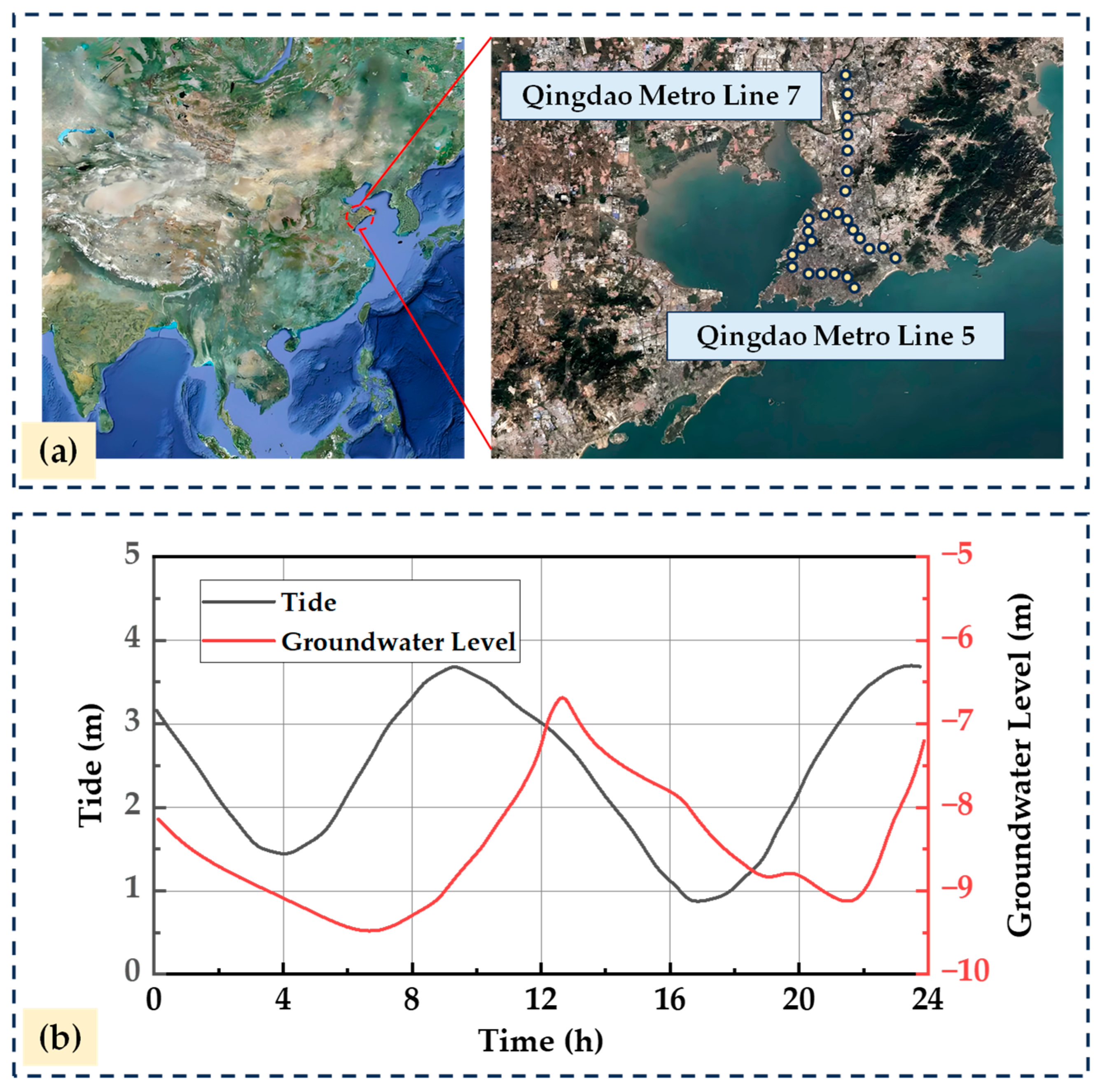
2.1. Project Overview

The proposed project involves a foundation pit in Qingdao City. As shown in Figure 2, the shield tunnel is located at the corner of the foundation pit, making its deformation highly susceptible to the spatiotemporal effects of excavation. The pit covers an area of approximately 6204.6 m2, with a depth ranging from 12.5 m to 14 m. Its dimensions are approximately 65 m in the east–west direction and 82 m in the north–south direction. During excavation, unevenly distributed artificial fill layers were encountered, with thicknesses varying between 2.7 m and 5.4 m. These layers primarily consist of construction debris and clay fill materials, characterized by complex composition and high compressibility. Beneath the artificial fill layers lie Quaternary strata and sedimentary layers formed by alluvial and diluvial processes. The geological composition mainly includes silty clay, silty clay interbedded with gravel, and cobble layers.

2.2. Test Method and Procedure

2.2.1. Statistical Evaluation of Tunnel Deformation Impacts

The impact of foundation pit construction on surrounding geotechnical bodies varies significantly across different strata in terms of disturbance range and intensity. In practical engineering scenarios, multiple factors, including excavation depth, horizontal clearance from existing structures, burial depth, diverse retaining systems, and geological conditions, collectively influence tunnel deformation patterns. This study therefore conducts statistical analysis on tunnel deformation data from typical soft soil region projects, aiming to investigate the effects of foundation pit excavation on existing tunnel deformations. The findings are expected to provide valuable insights for related research in coastal areas.

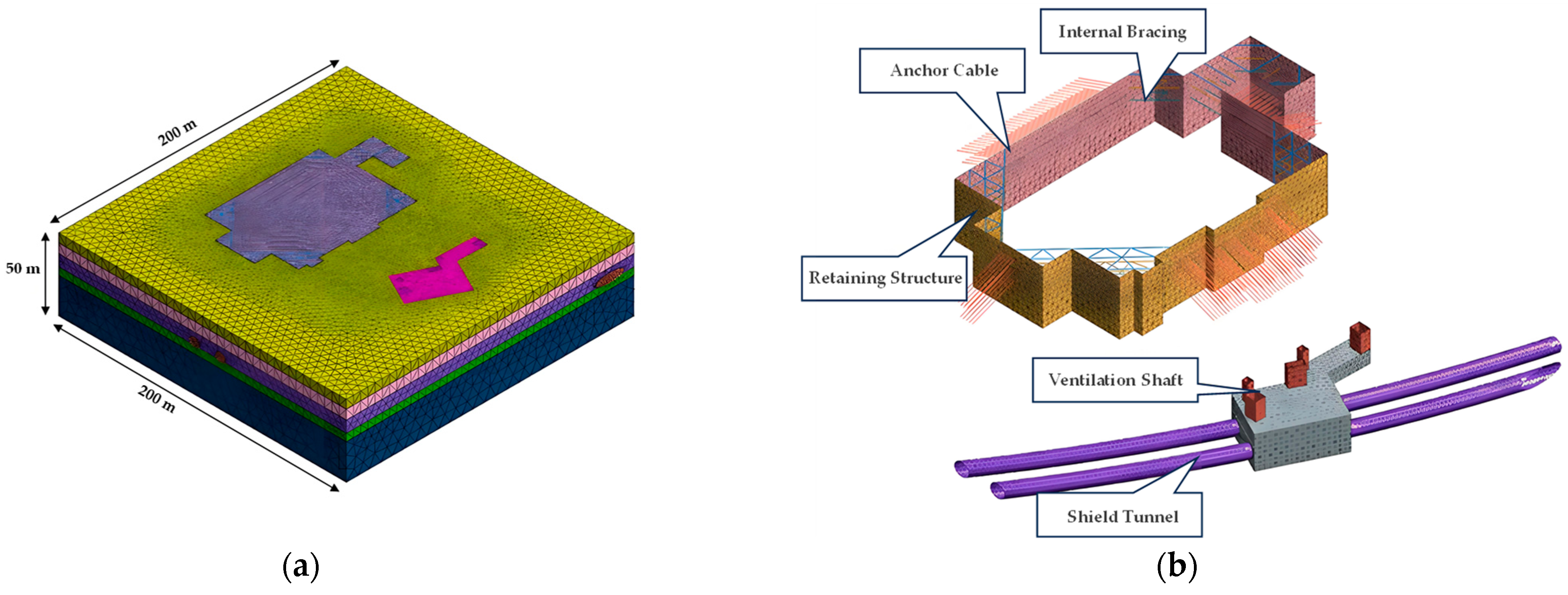
2.2.2. Numerical Simulation and Computation

This study employs MIDAS-GTS/NX 2021 software to conduct three-dimensional finite element calculations regarding the deformation of existing tunnels and corresponding control measures during foundation pit excavation construction. The study investigates tunnel displacement and bending moments in this engineering project. Furthermore, through parameter variations including horizontal clear distance between the foundation pit and tunnel, tunnel burial depth, and foundation pit enclosure structures (diaphragm wall thickness and embedment ratio of retaining structures), a sensitivity analysis is performed to examine the influence of critical factors on tunnel deformation.
The soil in the model adopts a modified Mohr–Coulomb constitutive material. By defining the unloading deformation modulus of the soil, the model simulates various foundation types, particularly silty soil and muddy soil strata. To mitigate the base heave phenomenon caused by stress release during excavation, the unloading modulus was set to three times the loading modulus in the calculations. The soil parameters in the model adopted were simplified based on the engineering geological survey report. Strata with similar mechanical properties were merged, and the model was ultimately simplified into five layers. The mechanical parameters of the strata are listed in Table 1.
Given the large dimensions of the excavation in this project, the bored pile retaining structure was converted into a diaphragm wall using the equivalent stiffness method for simplified calculations. The conversion formula is as follows [30]:
h = 0.838 D D ( D + t ) 3
where h is the thickness of the equivalent diaphragm wall, m; D is the pile diameter, m; and t is the clear spacing between piles, m.
The equivalent diaphragm wall thickness is calculated to be 0.8 m.
In the numerical simulation analysis, the supporting structures—such as diaphragm walls and ground anchors, as well as shield tunnel linings—are categorized into distinct structural types and modeled using elastic constitutive models to describe their behavior. For diaphragm walls, which exhibit plate-like characteristics, plate elements are selected for simulation. The tunnel structure, due to its three-dimensional geometry, is simulated with solid elements. Horizontal struts in the excavation are modeled using beam elements to accurately capture their lateral load-bearing capacity. Ground anchors are represented through embedded truss models, which effectively describe the interaction between the anchors and surrounding soil. All parameters required for these simulations—including material properties and dimensions—are configured based on the data provided in Table 2 to ensure the accuracy of the results.
The model establishes a coordinate system with the center of the excavation as the origin. To mitigate boundary effects, the model boundaries were set at 3 to 5 times the excavation width in depth. Considering the relative positional relationships of the tunnel, the X-axis direction was defined as 200 m, the Y-axis direction as 200 m, and the Z-axis direction as 50 m. To simulate potential boundary conditions in actual engineering, horizontal displacement constraints were applied to the lateral sides of the model, vertical constraints to the bottom, and the top boundary was set as free. The mesh generation of the model is illustrated in Figure 3a, with detailed meshing of the shield tunnel and excavation support structures shown in Figure 3b. This meshing approach facilitates precise capture of structural interactions and their mechanical responses under loading.

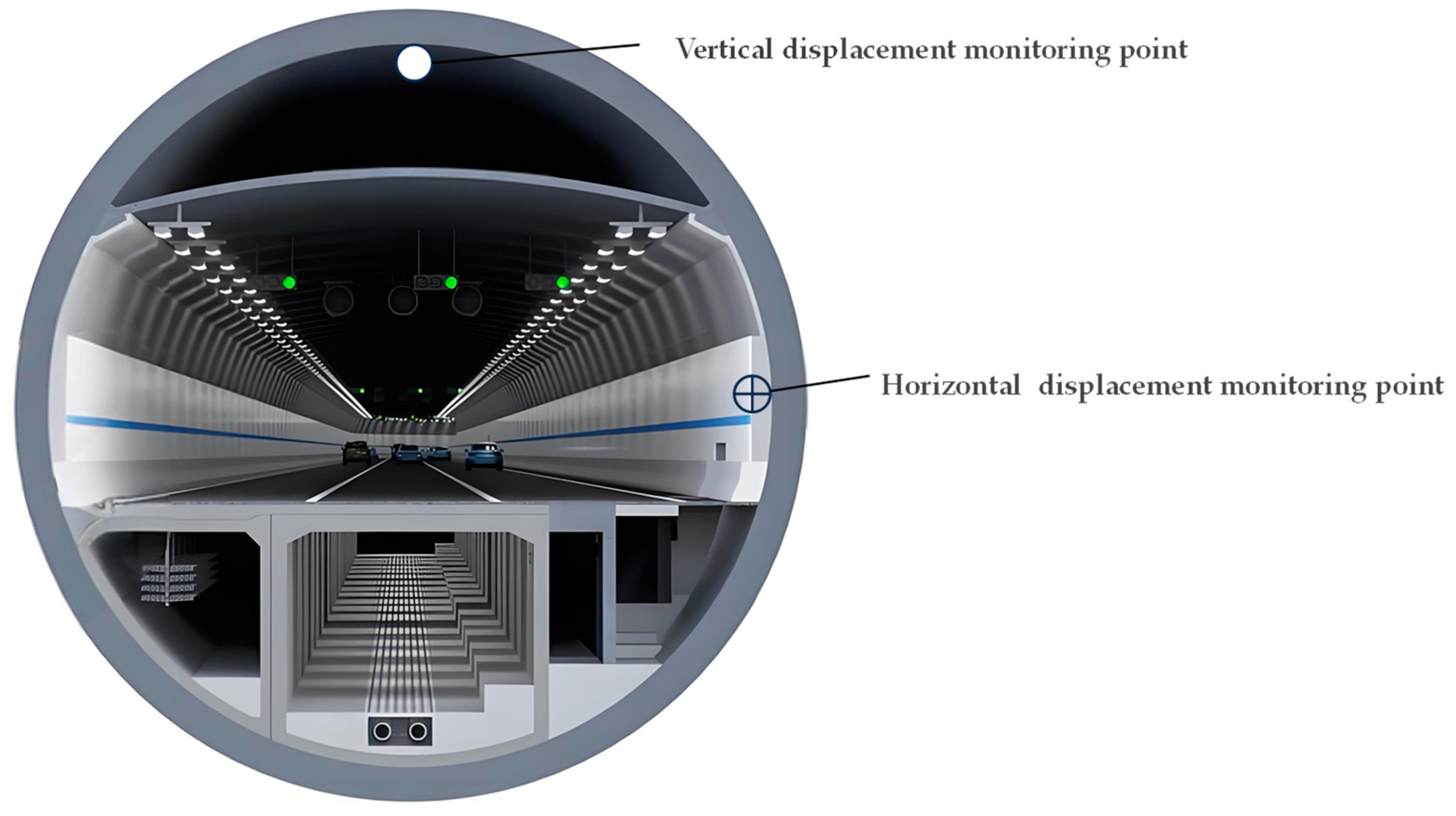
2.2.3. Field Measurement Study

The advantages of the field measurement method lie in its authenticity and reliability. Through actual monitoring, the most accurate field data can be obtained to evaluate the practical impacts of foundation pit excavation on existing tunnels. Based on the affected zone in this project, displacement analysis of shield tunnels during different construction phases was conducted. The configuration of monitoring cross-sections is illustrated in Figure 2. The layout of monitoring points within tunnel cross-sections is shown in Figure 4.
Simultaneously determining appropriate monitoring control values and warning thresholds for surveillance items is a comprehensive process that requires consideration of specific project conditions and relevant construction specifications. Through consultation between the construction unit and the monitoring unit, the finalized monitoring plan is shown in Table 3.

3. Results

3.1. Results of the Statistical Evaluation of Tunnel Deformation Impacts

Statistical analysis was conducted on tunnel deformation characteristics in 30 foundation pit projects adjacent to existing tunnels within typical soft soil regions, with partial data summarized in Table 4 [31].
The statistical results revealed a maximum excavation depth of 17.3 m, a minimum depth of 4.75 m, and an average depth of 10.2 m. Among these projects, 70% exhibited vertical tunnel deformations below 10 mm, with the maximum vertical deformation not exceeding 16 mm. Geographically, 47% of the projects were situated in silt layers, while 50% were in silty clay layers. Notably, 93% of projects in silt layers demonstrated deformations below 10 mm, compared to only 40% in silty clay layers. This disparity suggests that existing tunnels in silty clay are more significantly affected by adjacent excavations than those in silt. Mechanistically, silt’s low cohesion renders it highly susceptible to disturbance, whereas silty clay—with its high water and clay contents and plasticity—exhibits greater deformation resistance under specific conditions. The observed statistical variations arise from regional geological heterogeneity and additional factors such as the relative position, horizontal distance, and burial depth between excavations and tunnels. Therefore, a comprehensive sensitivity analysis integrating these variables is essential for accurate risk assessment and mitigation.

3.2. Analysis of Numerical Simulation Results

3.2.1. Numerical Simulation Results of Field Working Conditions

Based on the parameters from Section 2 and the established site condition model, the influence of foundation pit excavation on the bending moments of shield tunnels obtained through phased excavation is illustrated in Figure 5, revealing that after the completion of the first soil layer excavation the bending moments at the crown and invert of the shield tunnel decreased, while those at the haunches increased. However, the overall variation in bending moments was not significant, with changes limited to approximately 5 kN·m. Following the second soil layer excavation, the bending moment changes slightly increased compared to the first excavation stage. These observations indicate that during the early stages of foundation pit excavation, the impact on the shield tunnel remains relatively minor. After the third and fourth soil layer excavations, the bending moments at various points of the tunnel gradually increased and exhibited specific patterns. Bending moments at the haunches increased significantly, while bending moments at the crown and invert decreased. Adjacent points to the crown and invert showed slightly larger bending moments, while other points exhibited smaller values. The tunnel’s long axis elongated, and the short axis shortened, resulting in a “flattened duck egg” shape (compressed vertically and elongated horizontally). Upon completion of the foundation pit excavation, the bending moments further expanded. The “flattened duck egg” shape became more elongated, with bending moments at the top, bottom, left, and right points fluctuating around 80 kN·m. Since the bending moment value is significantly less than the design bending moment value, the entire foundation pit excavation process will not induce durability-related cracking in the tunnel segments.
The displacement response of shield tunnels induced by foundation pit excavation is illustrated in Figure 6. As shown in Figure 6a, during the first two excavation stages, tunnel displacements preferentially develop toward the excavation side with magnitudes below 1 mm. Commencing with the third excavation stage, displacement magnitudes exhibit progressive amplification, particularly demonstrating maximum offset in the upper-right quadrant. Post-excavation monitoring reveals significant horizontal displacement expansion, where left-side displacements (maximum 3.57 mm at point 3) systematically exceed right-side values (minimum 0.2 mm at point 11), confirming non-uniform deformation characteristics.
Figure 6b delineates the evolutionary pattern of vertical displacements. Initial excavation phases (Stages 1–2) induce generalized heave with limited magnitude (<0.8 mm). Transitioning to Stage 3, differential vertical movements emerge with crown settlement and invert heave developing synchronously, though constrained within 1.2 mm. Final excavation completion triggers predominant subsidence, particularly above the demarcation line connecting Points 6–14, where maximum settlement reaches 3.11 mm at Point 1. Contrastingly, displacements below this boundary remain sub-0.5 mm (minimum 0.2 mm at Point 8), establishing pronounced vertical deformation heterogeneity.

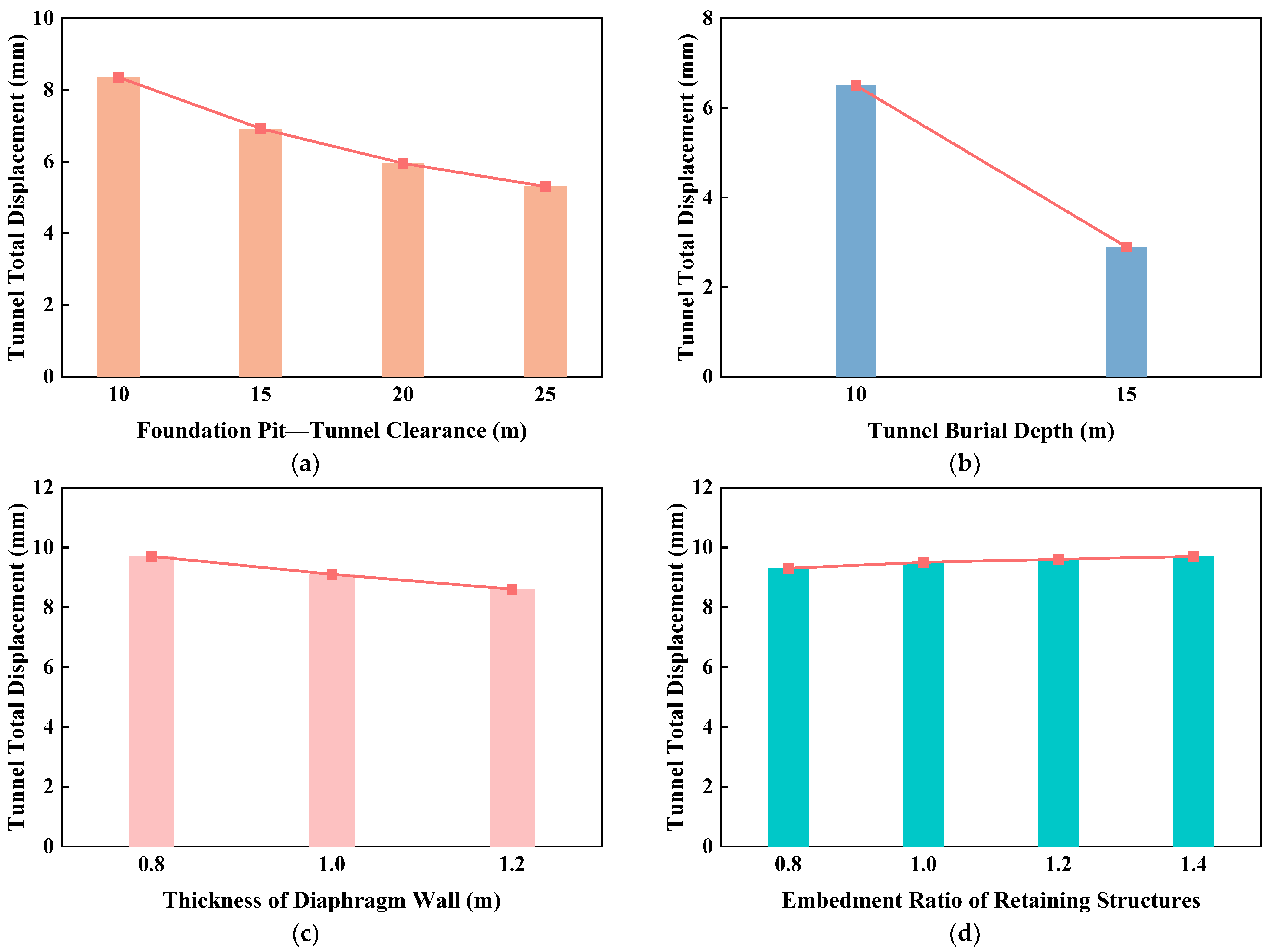
3.2.2. Influence of Horizontal Clear Distance Between Foundation Pit and Tunnel

Under constant conditions for other factors, this study set horizontal clear distances between the foundation pit and tunnel at 10 m, 15 m, 20 m, and 25 m to observe the impact of excavation on adjacent tunnel deformation.
Based on the analysis in Figure 7, it can be observed that as the excavation depth of the foundation pit increases, the horizontal clear distance between the pit and the tunnel also increases, leading to a gradual reduction in both the total and vertical displacements of the tunnel. During the initial stages of excavation (e.g., at depths of 3 m and 6 m), the horizontal displacement of the tunnel initially increased and then gradually decreased with an increase in the horizontal clear distance. Notably, the maximum displacement occurred at a horizontal clear distance of 15 m, after which displacement began to diminish. This phenomenon primarily arises because the increasing horizontal clear distance alters the spatial angle between the tunnel and the excavation center as excavation progresses. These angular changes influence the force distribution and displacement patterns acting on the tunnel, thereby driving the observed displacement trends. In summary, increasing the horizontal clear distance between the foundation pit and the tunnel effectively mitigates displacement during excavation.

3.2.3. Influence of Tunnel Burial Depth

Two numerical models were established with a fixed horizontal clear distance of 7.4 m between the tunnel and foundation pit, and tunnel burial depths of 10 m and 15 m, respectively. Based on prior analyses indicating negligible tunnel deformation during the first two excavation stages, this study focused on the third and fourth excavation layers to investigate the impact of tunnel burial depth on shield tunnel behavior.
A comparative analysis of bending moment variations in tunnels with different burial depths in the same excavation layer (as shown in Figure 8) reveals that tunnels with shallower burial depths are more sensitive to excavation impacts. For the tunnel with a burial depth of 10 m, during the third excavation layer compression and tension phenomena began to emerge, and in the fourth excavation layer significant tension was observed at the left and right ends of the shield tunnel, accompanied by pronounced compression at the crown and invert. In contrast, for the tunnel with a burial depth of 15 m, compression effects during the third excavation layer were negligible, and while bending moment changes increased substantially in the fourth layer they remained smaller than those for the 10 m burial depth. This indicates that the bending moments at all tunnel sections for the 10 m burial depth consistently exceeded those for the 15 m burial depth across excavation stages. As excavation progressed from the third layer onward, the lateral bending moments of the shield tunnel increased, while vertical bending moments exhibited a decreasing trend. The tunnel displayed marked tension at its left and right ends and significant compression at the crown and invert, forming a distinct “flattened duck egg” shape. This deformation pattern became even more pronounced following the completion of the fourth excavation layer.
An analysis of displacement variations in tunnels with different burial depths during each excavation stage (Figure 9) reveals that tunnels with shallower burial depths are more significantly affected by foundation pit excavation, exhibiting more pronounced displacement changes. As the excavation progresses, displacements at all tunnel points gradually increase, reaching their maximum variations at the completion of excavation. Furthermore, a demarcation line connecting Points 6–14 highlights that both horizontal and vertical displacements on the upper-right side of the tunnel exceed those on the lower-left side, resulting in non-uniform displacement distribution. The settlement deformation of the tunnel predominantly orients toward the excavation side, emphasizing the spatial bias in displacement patterns.

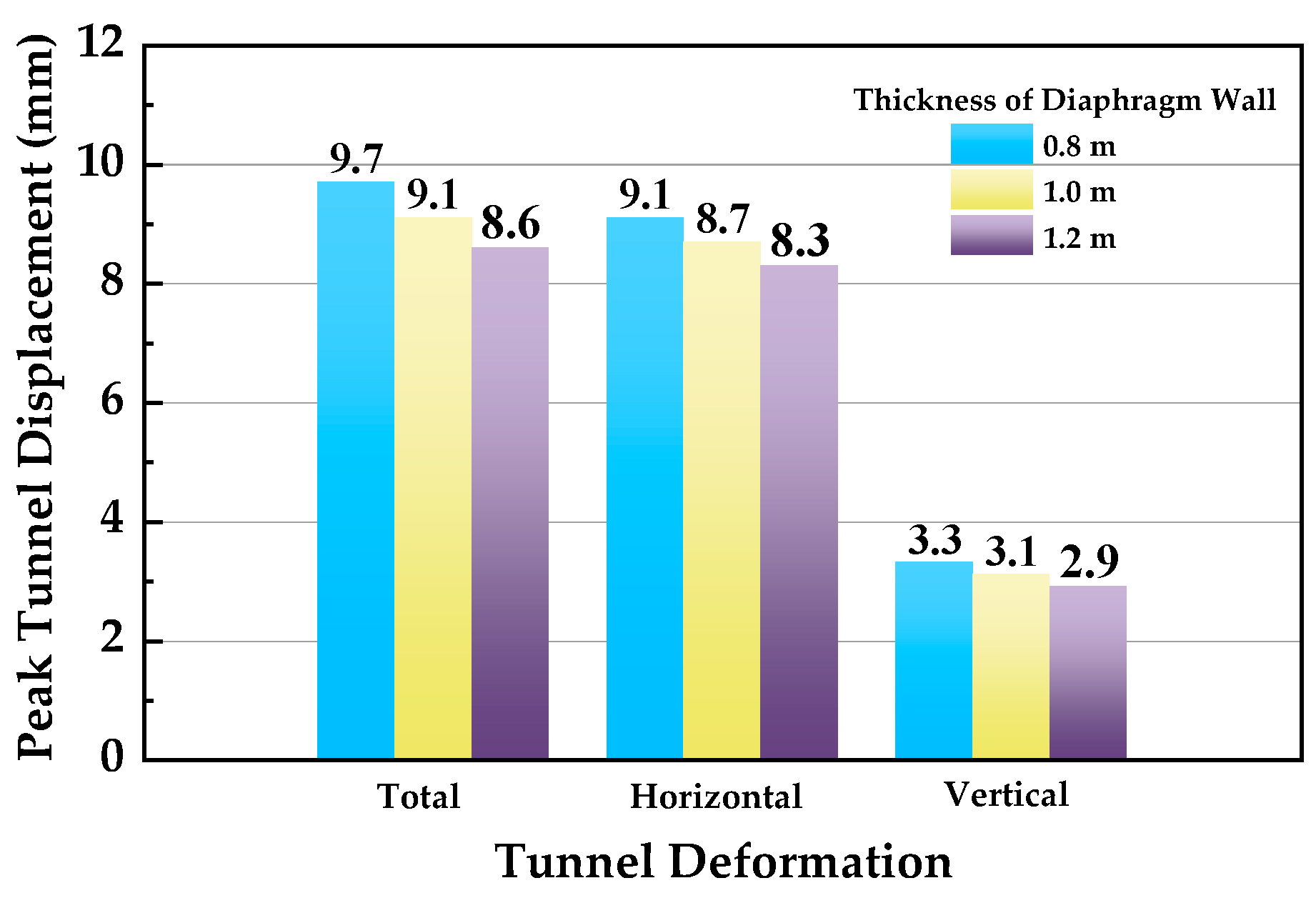
3.2.4. Influence of Diaphragm Wall Thickness

The retaining pile structure of foundation pits exhibits a strong correlation in deformation with adjacent existing subway tunnels, where variations in diaphragm wall thickness significantly influence the deformations of both the excavation and tunnels. This section employs the aforementioned numerical model to analyze the influence of diaphragm wall thickness on the deformations of the foundation pit and tunnels.
Analysis of the data in Figure 10 shows that when the thickness of the diaphragm wall increases from 0.8 m to 1.2 m, the surface settlement decreases from 16.9 mm to 6.3 mm (a reduction of 62.7%), and the horizontal displacement of the diaphragm wall decreases from 24.7 mm to 14.6 mm (a reduction of 40.9%). This indicates that increasing the thickness of the diaphragm wall significantly enhances the control of foundation pit deformation. However, when comparing the maximum base heave of the foundation pit, it is found that as the diaphragm wall thickness increases, the maximum base heave decreases only slightly from 36.5 mm to 33.2 mm, representing a mere 9% reduction. This suggests that variations in diaphragm wall thickness have limited effectiveness in controlling base heave. This phenomenon may be attributed to the fact that base heave is influenced by other factors, such as soil properties and the support system of the foundation pit, which remained unchanged in this study.
Following the completion of foundation pit excavation, observation of the data in Figure 11 reveals that as the thickness of the diaphragm wall increases from 0.8 m to 1.2 m, the total displacement, horizontal displacement, and vertical displacement of the tunnel all exhibit a downward trend, albeit with relatively minor reductions. Specifically, the total displacement decreases by 12.7%, horizontal displacement by 9.6%, and vertical displacement by 12.1%, none of which represent substantial reductions. This indicates that altering the thickness of the diaphragm wall has limited effectiveness in controlling tunnel displacement deformation.
Therefore, in practical foundation pit excavation projects, selecting an appropriate thickness for the diaphragm wall is crucial. This approach not only ensures the safety of adjacent tunnels but also achieves cost-effectiveness. Comprehensive consideration of all factors reveals that a diaphragm wall thickness of 1.0 m provides a relatively optimal balance between controlling excavation-induced deformations and minimizing economic costs. This implies that excessively increasing the diaphragm wall thickness during design and construction is unnecessary, as a 1.0 m thickness effectively balances economic efficiency and structural safety.

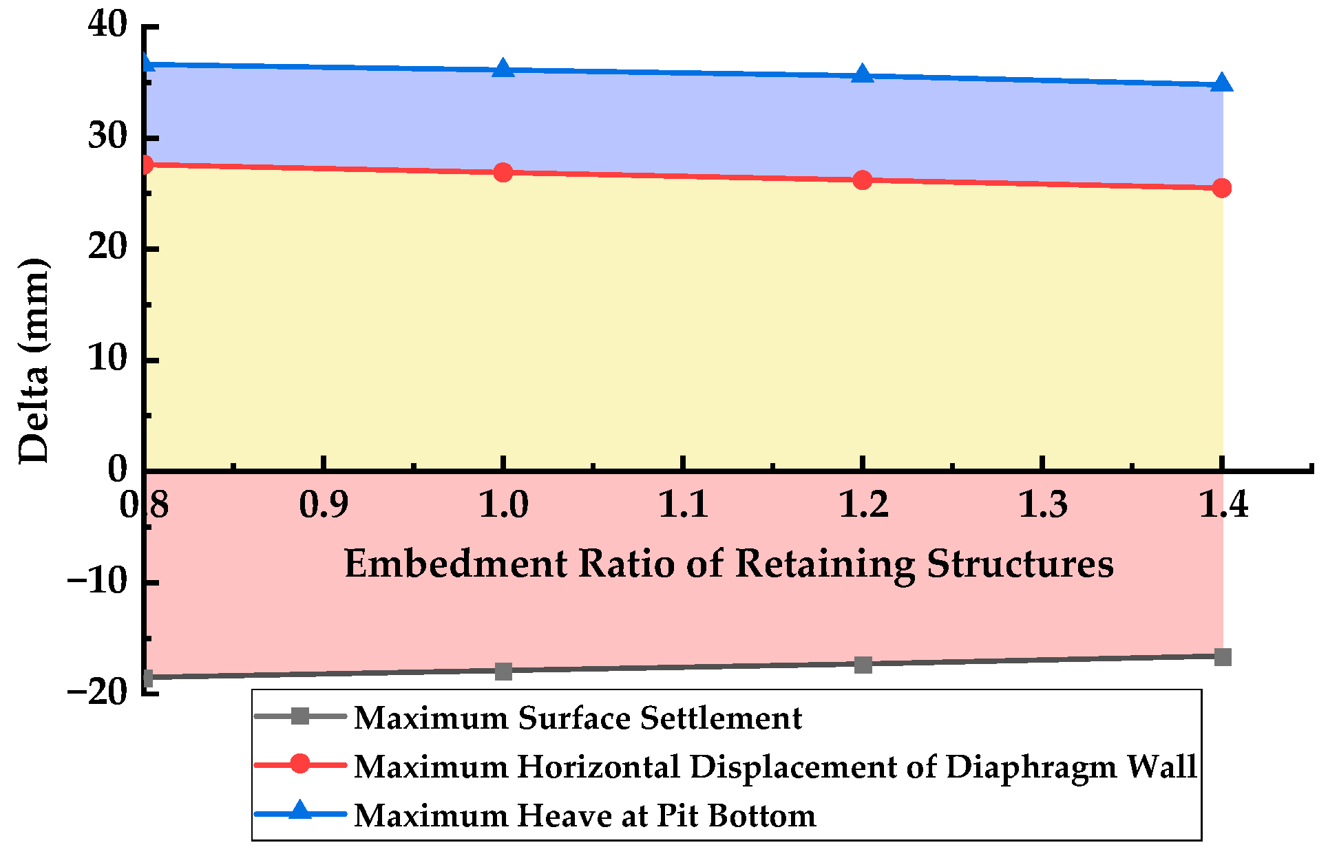
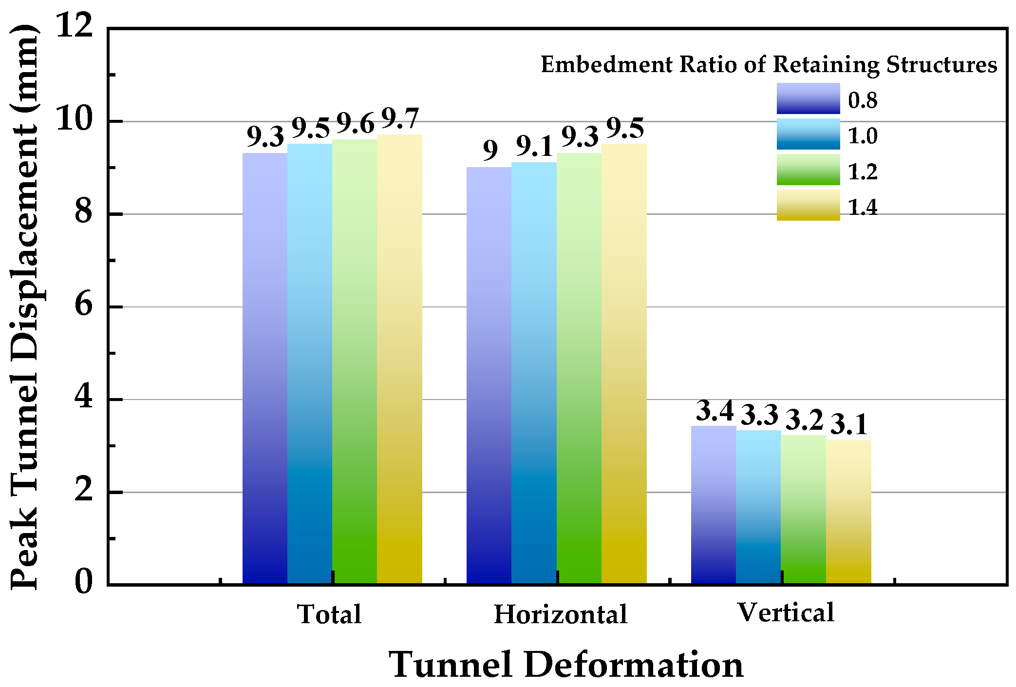
3.2.5. Influence of Retaining Structure Embedment Ratio

The embedment ratio of retaining structures is introduced to analyze the deformation impact on adjacent metro tunnels after the completion of foundation pit excavation. Based on the computational model mentioned above, calculations were performed for embedment ratios of 0.8, 1.0, 1.2, and 1.4.
As shown in Figure 12, both surface settlement and horizontal displacement of the diaphragm wall are notably influenced, with significant base heave observed at the foundation pit bottom. When the embedment ratio of the retaining structure increases from 0.8 to 1.2, the surface settlement decreases by 11.4%, the maximum horizontal displacement of the diaphragm wall decreases by 8.2%, and the maximum base heave reduces by 5.2%. While increasing the embedment ratio positively controls surface settlement, base heave, and maximum horizontal displacement of the diaphragm wall, the rate of deformation reduction slows progressively. These results demonstrate that modifying the embedment ratio of retaining structures has limited effectiveness in mitigating excavation-induced deformations.
As the embedment ratio of the retaining structure varies, the displacement deformation of the tunnel remains relatively minor (Figure 13). When the embedment ratio increases from 0.8 to 1.4, the total displacement changes by 0.4 mm (a variation magnitude of 4.1%), the horizontal displacement increases by 0.5 mm (4.1%), and the vertical displacement decreases by 0.6 mm (8.8%). These results indicate that altering the embedment ratio of the retaining structure exerts moderate effectiveness in controlling the deformation of adjacent tunnels, yet the overall impact on tunnel displacement mitigation remains limited.
Based on a comprehensive comparison, under the premise of ensuring excavation stability, adjusting the thickness of the diaphragm wall and the embedment ratio of the retaining structure has a significant impact on controlling foundation pit deformation, but exhibits relatively minor influence on controlling the deformation of adjacent tunnels.

3.3. Analysis of Field Measurement Data

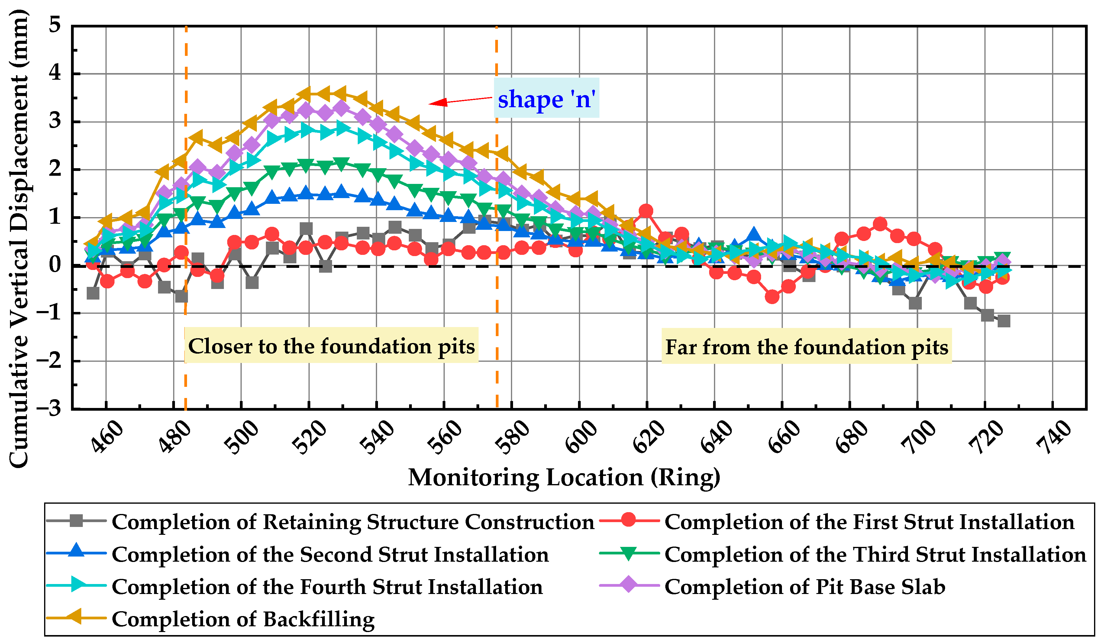
3.3.1. Vertical Displacement Analysis of Shield Tunnel

Figure 14 shows the vertical settlement variation curves of the tunnel during different construction stages. As observed from the figure, slight upward displacement (maximum approximately 1 mm) occurred in the tunnel during the construction of the retaining structure. This phenomenon is primarily attributed to disturbances in the stable underground soil layers caused by retaining structure construction activities, resulting in tunnel uplift.
Following foundation pit excavation completion, the tunnel deformation pattern transitioned to settlement, exhibiting a characteristic “n”-shaped heave profile where uplift zones predominantly concentrated on the pit-proximal side. The maximum tunnel heave induced by excavation reached 3.85 mm at the closest ring (Ring 530) to the pit, with the heave zone spanning Rings 480–575. This indicates that the influence range of foundation pit excavation on adjacent tunnels extends approximately 114 m.

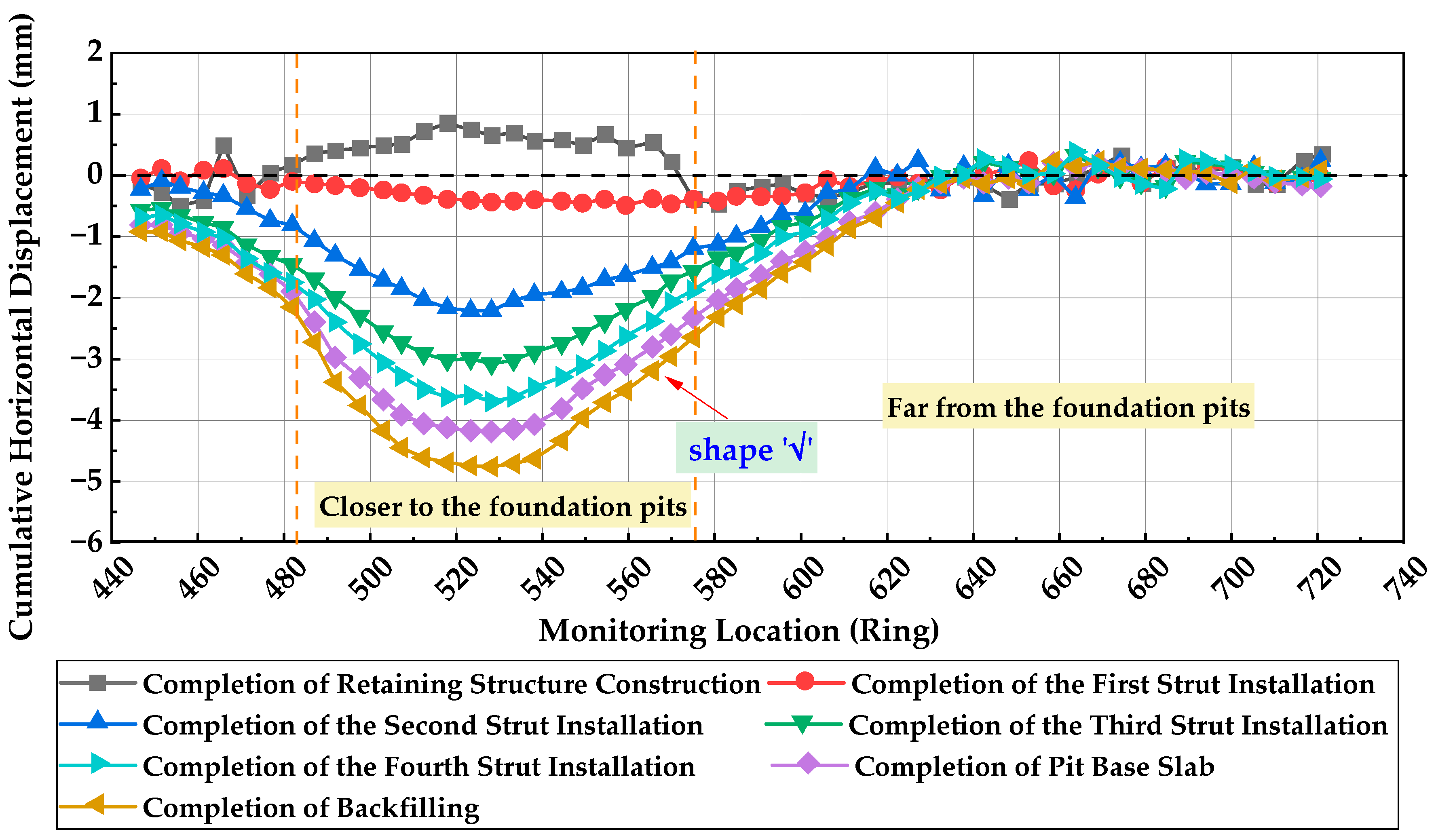
3.3.2. Shield Tunnel Horizontal Displacement Analysis

Figure 15 presents the horizontal displacement curves of the tunnel across various construction phases. Positive values indicate tunnel displacement away from the foundation pit, while negative values correspond to displacement towards the pit.
Following the completion of retaining structure construction, tunnel horizontal displacements remained within ±1 mm, indicating negligible deformation. As excavation proceeded, these displacements transitioned from positive to negative values with progressive escalation. This phenomenon is primarily attributed to stress relief in the soil mass due to pit unloading, which reduced lateral earth pressure on the tunnel segment adjacent to the excavation zone, consequently inducing inward deformation toward the pit.
During backfilling operations, horizontal displacements exhibited cumulative growth, peaking at near 6 mm upon completion of the pit base slab casting. Although displacements gradually stabilized post-backfilling, persistent monitoring remained crucial throughout this phase due to continued deformation risks.
The finalized horizontal displacement profile manifested a distinct “√”-shaped curve characterized by significantly amplified displacements (approaching 6 mm) with rapid deformation rates in pit-proximal tunnel segments, and progressively diminished displacements and decelerated deformation rates in distal sections. Maximum horizontal displacement occurred precisely at the tunnel location nearest to the excavation boundary.

4. Discussion

4.1. Analysis of Tunnel Deformation

Through the combined analysis of numerical simulation and field measurement data, the deformation influence patterns of coastal silty clay foundation pit excavation on adjacent existing tunnels were derived. As excavation progressed, the horizontal displacement of shield tunnels consistently developed towards the pit side, gradually increasing with excavation depth while exhibiting uneven transverse displacement variations. The maximum simulated horizontal displacement reached 3.57 mm, compared with a measured value of 4.79 mm. Regarding vertical displacement, monitoring points initially displayed an upward heave trend during early excavation stages, transitioning to subsidence after pit completion. The maximum simulated vertical displacement was 3.11 mm versus a measured 3.85 mm. Within the same monitoring plane, vertical displacements demonstrated bias towards the pit side, mirroring horizontal displacement patterns.
This trend aligns with observations reported in Reference [32]. The settlement non-uniformity primarily stems from stress redistribution in soil layers within a limited range around the excavation pit during deep excavation, which induces strain redistribution. This process triggers deformation of retaining structures, base heave at the pit bottom, and subsequent displacement of external soils, ultimately leading to tunnel deformation. When the retaining structure displacement is minor, the frictional resistance between the structure and surrounding soil effectively constrains surface settlement, resulting in smaller subsidence near the retaining walls. However, when retaining structure displacement becomes significant, this frictional resistance loses its restraining capacity, leading to pronounced subsidence near the external side of the retaining structure. Additionally, deformation of protective structures expands the elastic zone in external soils, enhancing soil movement toward the pit interior and exacerbating base heave. As excavation scope and depth increase, these effects progressively propagate through soil layers before transferring to adjacent tunnels and strata. During deep excavation, strain transmission occurs from the pit periphery toward excavated soils, while ground deformation propagates outward from excavated zones. This mechanism ultimately drives shield tunnel displacement toward the excavation side, as shown in Figure 16.

4.2. Sensitivity Analysis of Key Factors

The field-measured data in this study validated the accuracy of the numerical model. By adjusting parameters in the numerical simulation, the research investigated the effects of various factors including horizontal clear distance, burial depth of existing structures, and different retaining systems of foundation pits on tunnel deformation. Furthermore, it systematically analyzed the influence mechanisms of coastal foundation pit excavation on the deformation patterns of adjacent existing tunnels.
The influences of various factors on total tunnel displacement after foundation pit excavation are illustrated in Figure 17. As shown in the figure, all parameters exert varying degrees of influence on tunnel deformation. The maximum total displacement of shield tunnels progressively decreases with increasing horizontal clear distance between pit and tunnel, while simultaneously demonstrating a decreasing trend with greater tunnel burial depth. Regarding the pit’s retaining system, adjusting diaphragm wall thickness and embedment ratio can partially mitigate the maximum tunnel displacement. However, the mitigation extent remains limited. Practical engineering should adopt holistic consideration of tunnel displacement thresholds and economic factors when selecting parameters. Due to experimental constraints, this study primarily investigated deformation patterns of adjacent shield tunnels in coastal silty clay through numerical simulations, with more comprehensive multivariate analysis and field validation requiring further research.

5. Conclusions

Based on a foundation pit excavation project in Qingdao City, this study investigates the deformation patterns of adjacent existing tunnels induced by pit excavation through integrated approaches including statistical analysis, numerical simulation, and field monitoring. Sensitivity analysis was performed on critical factors influencing tunnel deformation to provide practical insights for deformation prevention and control. The main conclusions are as follows:
(1)
Analysis of 30 excavation cases near existing tunnels in different soft strata indicates that tunnels in silt strata exhibit deformation magnitudes below 10 mm with higher frequency compared to those in silty clay strata, suggesting greater susceptibility of tunnels in silty clay to adjacent excavations. Considering regional geological variations and influential factors including relative positioning, separation distance, and burial depth between excavations and existing tunnels, comprehensive sensitivity analysis incorporating multiple parameters is recommended.
(2)
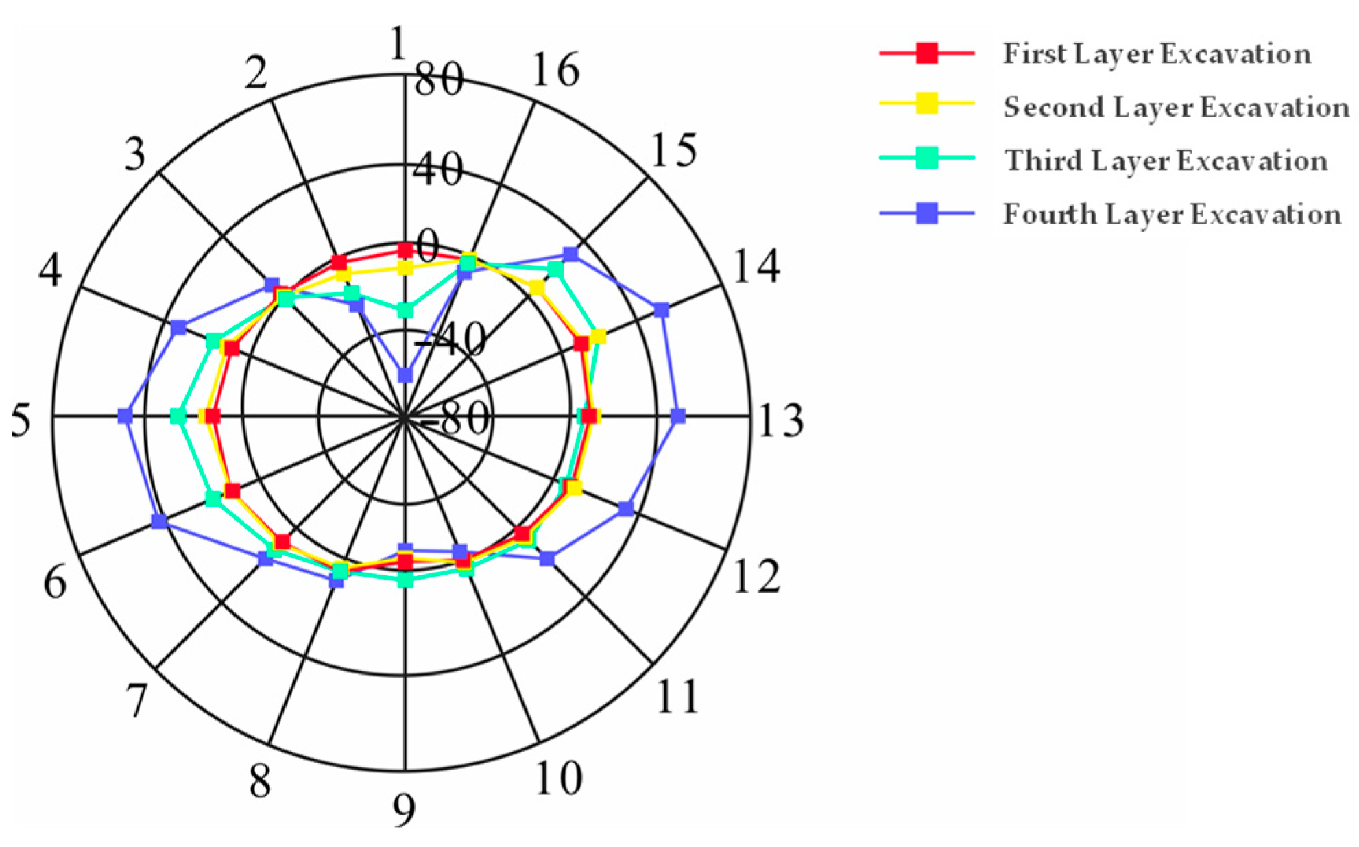
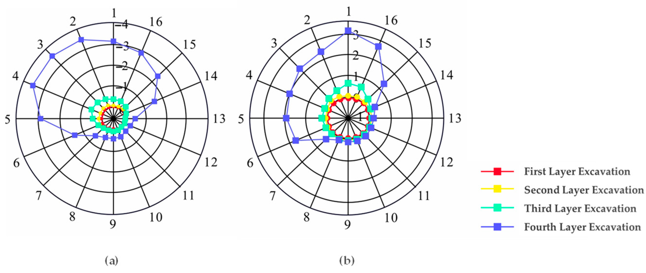
With increasing excavation depth, both bending moments and displacements of adjacent tunnels progressively intensify. During initial excavation stages, tunnel deformations remain relatively minor. Upon completion of excavation, lateral bending moments increase while vertical bending moments decrease, forming a horizontal oval bending moment distribution pattern. The tunnel demonstrates a global tendency to displace towards the excavation zone.
(3)
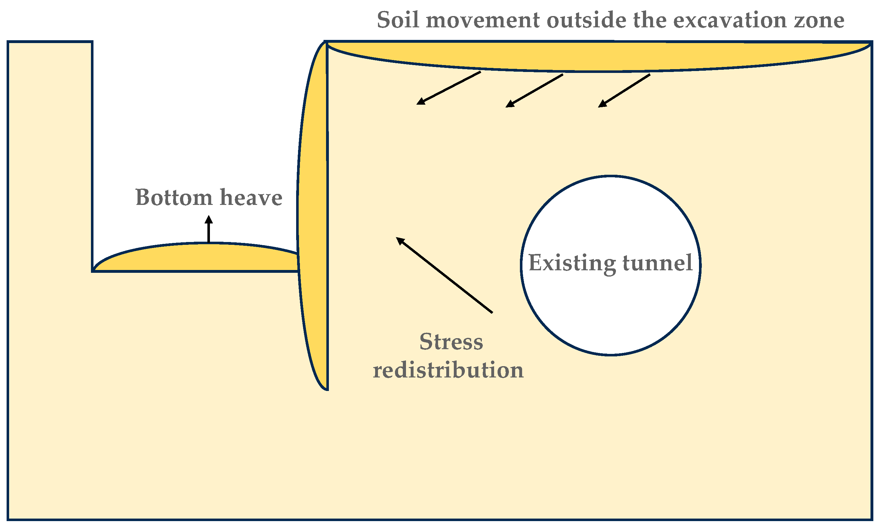
Monitoring data confirm that excavation-induced stress relief drives deep soil movement towards the pit, consequently displacing shield tunnels in the same direction. Both vertical and horizontal tunnel displacements progressively accumulate during excavation, exhibiting magnitude–distance correlation. Maximum tunnel settlement (3.85 mm) occurs at Ring 530 nearest to excavation, with the affected zone extending approximately 114 m. Maximum horizontal displacement approaches 5 mm, satisfying relevant code requirements. These findings provide scientific references for deformation control in existing tunnels within coastal silty clay strata.
(4)
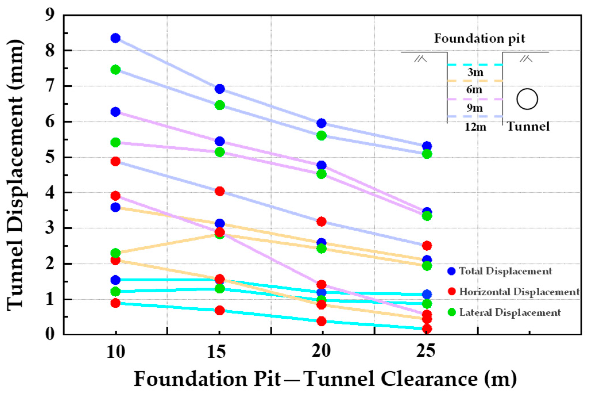
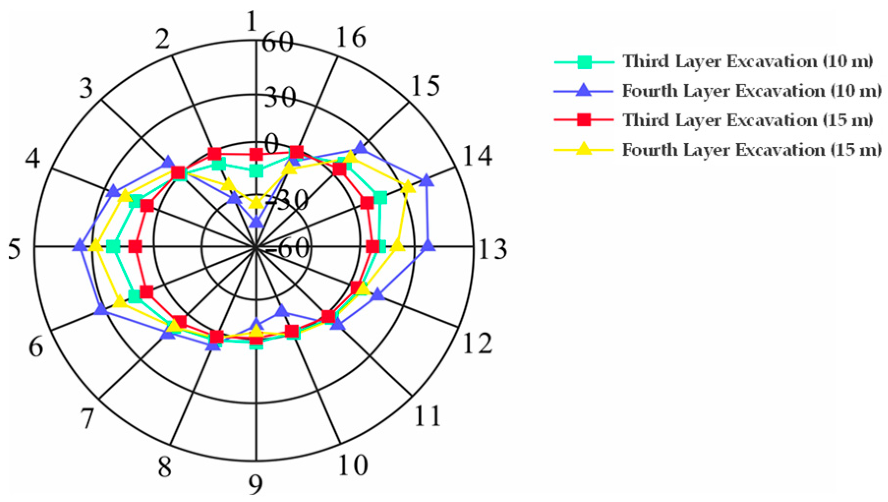
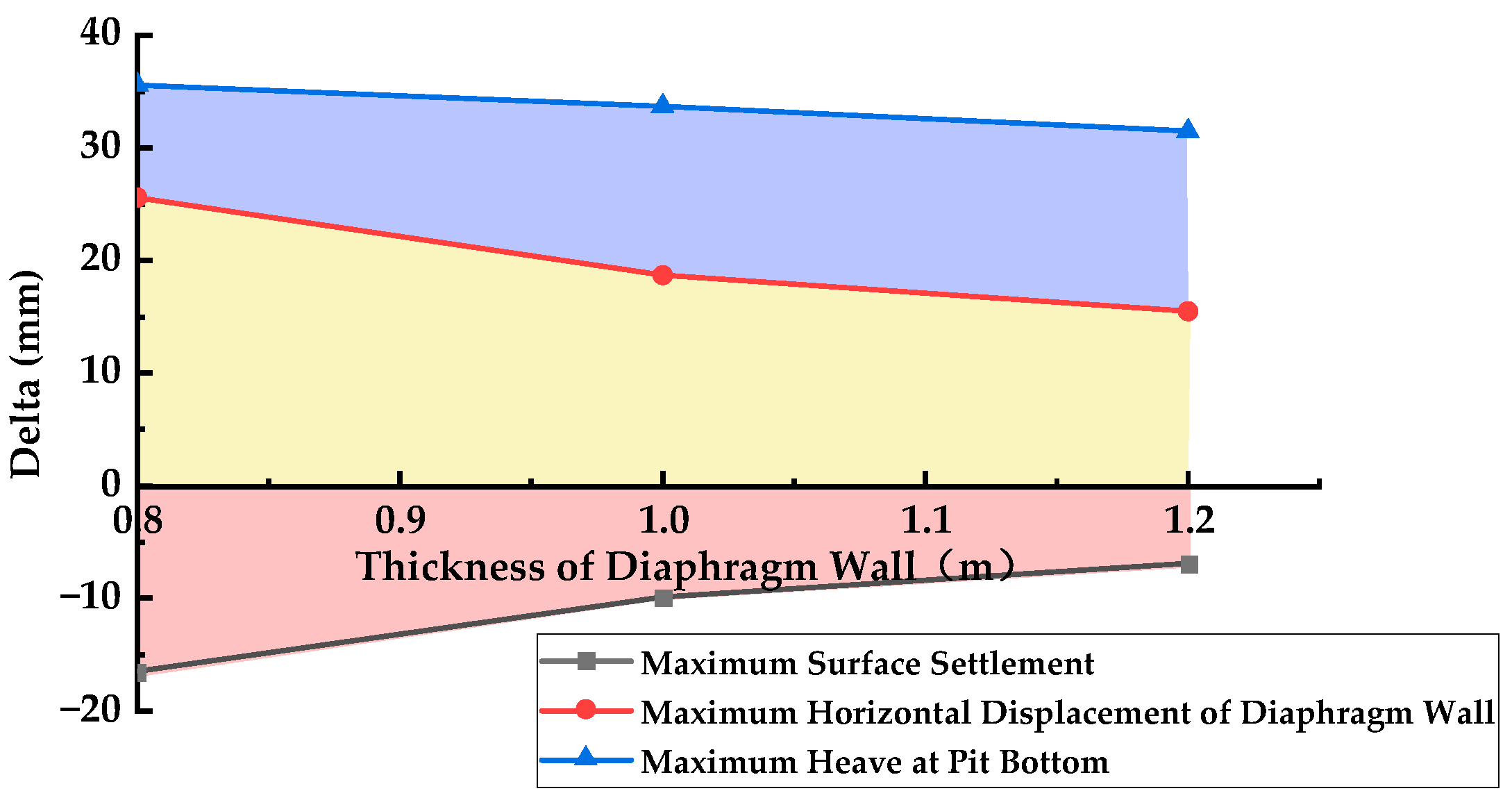
Sensitivity analysis of tunnel deformation in coastal silty clay. Within the same stratum, the horizontal clear distance between the excavation pit and the tunnel exerts significant influence on tunnel deformation. When the excavation is completed, the deformation of tunnels spaced 10 m apart increases by one-third compared to those spaced 25 m apart. The displacement vectors of the tunnel rotate counterclockwise from the upper left, with the maximum displacement gradually approaching the left haunch of the tunnel arch. Furthermore, tunnel burial depth also demonstrates notable impacts on displacement—shallower tunnels experience more severe deformation and greater displacement under excavation effects. However, under stable excavation conditions, modifying diaphragm wall thickness and the embedment ratio of pit retaining structures show limited effectiveness in controlling adjacent tunnel deformation. Additional measures targeting the tunnel side are required for effective deformation control. Field measurements are also necessary to further validate the sensitivity factors affecting tunnel deformation in coastal silty clay environments.

Author Contributions

Data curation, Y.L.; funding acquisition, T.L. and H.P.; investigation, Y.L., L.Y., Y.Z. and T.X.; methodology, Y.L. and J.Z.; project administration, Y.L., H.P., T.L. and J.Z.; writing— original draft, Y.L.; writing—review and editing, Y.L., H.P., L.Y. and T.L. All authors contributed to the article and approved the submitted version. All authors have read and agreed to the published version of the manuscript.

Funding

This research was funded by the Laoshan Laboratory (LSKJ202203500) and the National Natural Science Foundation of China (NO.42277139, NO.U2006213).

Data Availability Statement

The data used to support the findings of this study are included in the article.

Acknowledgments

The authors would like to thank Tongju Xing and Yuanzhe Zhan for their help during the experiment. Thank you to the Laoshan Laboratory and the National Natural Science Foundation of China for funding the project. Thanks to Shandong Engineering Research Center of Marine Exploration and Conservation for providing the test equipment.

Conflicts of Interest

The authors declare no conflicts of interest.

References

  1. Tian, P.; Wang, Z.; Li, J.; Cao, L.; Liu, Y.; Zhang, H.; Ai, S. Spatiotemporal characteristics and driving mechanism of high-intensity development of continental coastal zones in the East China Sea. Geogr. Res. 2023, 42, 156–171. [Google Scholar]
  2. Chen, X.; Li, K.; Bao, X.; Hong, C.; Fu, Y.; Cui, H. Innovations in the development of digital and intelligent Construction of urban shield tunnels. J. Basic Sci. Eng. 2021, 29, 1057–1074. [Google Scholar] [CrossRef]
  3. Su, D.; Huang, M.; Han, W.; Li, A.; Wang, E.; Chen, X. Suitability evaluation of underground space development in Shenzhen: Urban geoenvironmental considerations. Earth Sci. Front. 2023, 30, 514–524. [Google Scholar] [CrossRef]
  4. Wang, C.; Liu, L. Analysis on the future development trend of urban rail transit in China. Urban Rail Transit 2019, 22, 22–24. [Google Scholar] [CrossRef]
  5. Xu, X.; Deng, Y.; Zhou, L.; Ming, W.; Zhang, H.; Xia, C. Experimental study on temperature effect of consolidation and permeability of coastal soft soil. J. Eng. Geol. 2023, 2023, 1–8. [Google Scholar] [CrossRef]
  6. Liu, B.; Yu, Z.; Han, Y.; Wang, Z.; Zhang, R.; Wang, S. Analytical solution for the response of an existing tunnel induced by above-crossing shield tunneling. Comput. Geotech. 2020, 124, 103624. [Google Scholar] [CrossRef]
  7. Zhang, Z.G.; Huang, M.S.; Wang, W.D. Evaluation of deformation response for adjacent tunnels due to soil unloading in excavation engineering. Tunn. Undergr. Space Technol. 2013, 38, 244–253. [Google Scholar] [CrossRef]
  8. Liang, R.; Wu, W.; Yu, F.; Jiang, G.; Liu, J. Simplified method for evaluating shield tunnel deformation due to adjacent excavation. Tunn. Undergr. Space Technol. 2018, 71, 94–105. [Google Scholar] [CrossRef]
  9. Fu, Y.; Wang, B.; Wu, H.; Chen, X.; Sun, X.; Bian, Y.; Shen, X. Theoretical analysis on horizontal rectification of tunnel near deep foundation pit by grouting. Tunn. Undergr. Space Technol. 2023, 133, 104977. [Google Scholar] [CrossRef]
  10. Huang, X.; Schweiger, H.F.; Huang, H. Influence of Deep Excavations on Nearby Existing Tunnels. Int. J. Geomech. 2013, 13, 170–180. [Google Scholar] [CrossRef]
  11. Sun, H.; Chen, Y.; Zhang, J.; Kuang, T. Analytical investigation of tunnel deformation caused by circular foundation pit excavation. Comput. Geotech. 2019, 106, 193–198. [Google Scholar] [CrossRef]
  12. Bian, X.; Hu, H.; Zhao, C.; Ye, J.; Chen, Y. Protective effect of partition excavations of a large-deep foundation pit on adjacent tunnels in soft soils: A case study. Bull. Eng. Geol. Environ. 2021, 80, 5693–5707. [Google Scholar] [CrossRef]
  13. Wei, G.; Feng, F.; Cui, Y.; Wang, X.; Diao, H.; Wu, Y. Research on the influence of foundation pit excavation on the lateral force and deformation of side shield tunnels based on full-scale experiments. Tunn. Undergr. Space Technol. 2023, 140, 105236. [Google Scholar] [CrossRef]
  14. Masayasu, H.; Shiro, O.; Tatsuaki, K.; Ohmae, Y. Effects of the ring-cut excavation method on ground displacements and stability of a tunnel face. J. Tunn. Eng. 2017, 17, 1–8. [Google Scholar]
  15. Yu, Z.T.; Wang, H.Y.; Wang, W.; Ling, D.S.; Zhang, X.D.; Wang, C.; Qu, Y.H. Experimental and Numerical Investigation on the Effects of Foundation Pit Excavation on Adjacent Tunnels in Soft Soil. Math. Probl. Eng. 2021, 2021, 5587857. [Google Scholar] [CrossRef]
  16. Li, M.; Chen, J.; Wang, J.; Zhu, Y. Comparative study of construction methods for deep excavations above shield tunnels. Tunn. Undergr. Space Technol. 2018, 71, 329–339. [Google Scholar] [CrossRef]
  17. Shi, J.; Ng, C.W.W.; Chen, Y. Three-dimensional numerical parametric study of the influence of basement excavation on existing tunnel. Comput. Geotech. 2015, 63, 146–158. [Google Scholar] [CrossRef]
  18. Shi, J.; Ng, C.W.W.; Chen, Y. A simplified method to estimate three-dimensional tunnel responses to basement excavation. Tunn. Undergr. Space Technol. 2017, 62, 53–63. [Google Scholar] [CrossRef]
  19. Zhang, D.; Xie, X.; Li, Z.; Zhang, J. Simplified analysis method for predicting the influence of deep excavation on existing tunnels. Comput. Geotech. 2020, 121, 103477. [Google Scholar] [CrossRef]
  20. Li, D.; Liao, F.; Wang, L.; Lin, J.; Wang, J. Multi-Stage and Multi-Parameter Influence Analysis of Deep Foundation Pit Excavation on Surrounding Environment. Buildings 2024, 14, 297. [Google Scholar] [CrossRef]
  21. Zhuang, Y.; Cui, X.; Hu, S. Numerical simulation and simplified analytical method to evaluate the displacement of adjacent tunnels caused by excavation. Tunn. Undergr. Space Technol. 2023, 132, 104879. [Google Scholar] [CrossRef]
  22. He, C.; Cai, Y.; Pu, C.; Zhou, S.; Di, H.; Zhang, X. Deformation analysis and protection measures of existing metro tunnels effected by river channel excavation in soft soils. Tunn. Undergr. Space Technol. 2024, 144, 105504. [Google Scholar] [CrossRef]
  23. Zhang, J.; Xie, R.; Zhang, H. Mechanical response analysis of the buried pipeline due to adjacent foundation pit excavation. Tunn. Undergr. Space Technol. 2018, 78, 135–145. [Google Scholar] [CrossRef]
  24. Zhao, Y.; Chen, X.; Hu, B.; Wang, P.; Li, W. Evolution of tunnel uplift induced by adjacent long and collinear excavation and an effective protective measure. Tunn. Undergr. Space Technol. 2023, 131, 104846. [Google Scholar] [CrossRef]
  25. Zhang, X.; Wei, G.; Lin, X.; Xia, C.; Wei, X. Transverse Force Analysis of Adjacent Shield Tunnel Caused by Foundation Pit Excavation Considering Deformation of Retaining Structures. Symmetry 2021, 13, 1478. [Google Scholar] [CrossRef]
  26. Niu, Y.; Wang, Q.; Ma, F. Study on the Influence of Foundation Pit Excavation on the Deformation of Adjacent Subway Tunnel in the Affected Area of Fault Zones. Sustainability 2023, 15, 9462. [Google Scholar] [CrossRef]
  27. Zhang, S.; Li, X. Numerical analysis of deep foundation pit zoned excavation. Low Temp. Archit. Technol. 2012, 2012, 113–115. [Google Scholar]
  28. Chen, J.J.; Wang, J.H.; Xiang, G.W.; Wen, S.L.; Du, Y. Numerical study on the movement of existing tunnel due to deep excavation in Shanghai. Geotech. Eng. J. SEAGS AGSSEA 2011, 42, 30–40. [Google Scholar]
  29. Chen, J.; Liu, W.; Sun, X. Effects of Tuned Rail Damper on Track Dynamic Characteristics Optimization. Procedia Eng. 2017, 199, 1616–1622. [Google Scholar] [CrossRef]
  30. Ruan, H.T.; Zhao, J.H.; Huang, W.D.; Liu, L. Design and analysis of concurrent excavation of adjacent deep foundation pits. Chin. J. Geotech. Eng. 2010, 32, 146–150. [Google Scholar]
  31. Wei, G. Measurement and analysis of impact of foundation pit excavation on below existed shield tunnels. Rock Soil Mech. 2013, 34, 1421–1428. [Google Scholar] [CrossRef]
  32. Jian, R.; Huang, R.; Xu, C.X. Influence of deep excavation on the adjacent existing shielded tunnel in Hangzhou area. Soil Eng. Found. 2023, 37, 982–986. [Google Scholar]
Figure 1. (a) Distribution map of metro foundation pits in the coastal area of Qingdao. (b) Groundwater level of a coastal foundation pit on Qingdao Metro Line 5.
Jmse 13 00773 g001
Figure 2. Schematic diagram of the location of a foundation pit and tunnel in Qingdao.
Jmse 13 00773 g002
Figure 3. Mesh generation of the numerical computational model: (a) integrated model and (b) shield tunnel and excavation supporting structures.
Jmse 13 00773 g003
Figure 4. Layout of tunnel cross-section monitoring points.
Jmse 13 00773 g004
Figure 5. Variation of tunnel bending moments for field conditions. The radial coordinate denotes the bending moment (kN·m), and the circumferential coordinate indicates the measurement point ID.
Jmse 13 00773 g005
Figure 6. Variation of tunnel displacement under field conditions. The radial coordinate denotes displacement and the circumferential coordinate indicates measurement point ID. (a) Horizontal displacement. (b) Vertical displacement.
Jmse 13 00773 g006
Figure 7. Influence of horizontal clear distance on the central displacement of the tunnel.
Jmse 13 00773 g007
Figure 8. Variation of bending moments in tunnels with different excavation depths. The radial coordinate denotes bending moment (kN·m), and the circumferential coordinate indicates the measurement point ID.
Jmse 13 00773 g008
Figure 9. Variation of tunnel displacement for different excavation depths. The radial coordinate denotes displacement; and the circumferential coordinate indicates measurement point ID. (a) Horizontal displacement. (b) Vertical displacement.
Jmse 13 00773 g009
Figure 10. Influence of diaphragm wall thickness on foundation pit deformation.
Jmse 13 00773 g010
Figure 11. Influence of diaphragm wall thickness on tunnel deformation.
Jmse 13 00773 g011
Figure 12. Influence of retaining structure embedment ratio on foundation pit deformation.
Jmse 13 00773 g012
Figure 13. Influence of retaining structure embedment ratio on tunnel deformation.
Jmse 13 00773 g013
Figure 14. The vertical settlement variation curves of the tunnel during different construction stages.
Jmse 13 00773 g014
Figure 15. The horizontal displacement curves of the tunnel across various construction phases.
Jmse 13 00773 g015
Figure 16. Deformation and stress variation patterns in adjacent tunnels induced by foundation pit excavation and unloading.
Jmse 13 00773 g016
Figure 17. Impact analysis of key geological and construction factors on tunnel deformation. (a) Foundation pit–tunnel clearance. (b) Tunnel burial depth. (c) Thickness of diaphragm wall. (d) Embedment ratio of retaining structures.
Jmse 13 00773 g017
Table 1. Mechanical parameters of modeled soils.
Properties of the SoilUnit Weight (kN/m3)Cohesion (kPa)Friction Angle (°)Elastic Modulus (kN/m2)
Miscellaneous fill1910185000
Silty clay19.215204830
Silty clay19.337.5185630
Silty clay with gravel19.637.5206270
Completely weathered diorite20452025,000
Table 2. Structural element parameters.
StructuresElement TypeElastic Modulus (GPa)Poisson’s Ratio
Shield segmentPlate34.50.2
Diaphragm wallPlate300.2
Internal strutBeam300.2
Ground anchorEmbedded Truss2100.3
Table 3. Tunnel structural monitoring control values.
Monitoring ItemsControl Values
Accumulated ValuesVariation RateAlert Thresholds
Horizontal displacement5 mm1 mm/d10 mm
Vertical displacement5 mm1 mm/d10 mm
Total displacement5 mm1 mm/d10 mm
Table 4. Partial list of foundation pit projects adjacent to tunnels [31].
Foundation Pit ProjectExcavation Depth (m)Relative Position to TunnelMinimum Clear Distance (m)Tunnel Deformation
(Max. Uplift, mm)
Main Stratigraphic Conditions
A foundation pit adjacent to Hangzhou metro Station16.8Tunnel above the side of the pit9.3−7.8Sandy silt
Hangzheng storage plots 86-1,2 15.8Tunnel above the side of the pit4.5+9.0Sandy silt
Jianggan district Weidong pit, Hangzhou 12.55Tunnel above the side of the pit17.3+5.3Clayey silt
A building foundation pit, Jianggan district, Hangzhou5.7Tunnel below the side of the pit24+3.1Clayey silt
Xiasha economic zone pit, Hangzhou11.8Tunnel below the side of the pit11−4.5Sandy silt
Hangzheng storage plot No. 16 10.7Tunnel below the side of the pit10.5−4.4Silty clay
Shanghai Dongfang Road interchange project6.5Up/Down Tunnels in Sections No. 1/No. 22.76Up: +11.56, Down: +12.3Silty clay
Shanghai East-West underground express tunnel (Pudong Section)10.245° diagonally crossing below the pit4Up: +12.10, Down: +14.20Silty clay
Nanjing Longpan Road tunnel (South Section) West Pit 7.970° diagonally crossing below the pitLeft 2.73, Right 2.15Left: +3.20, Right: +5.50Silty clay
Tianjin West Station underground tunnel4.75Below existing metro box structure 0.3Cumulative uplift: +8.10Silty clay
Disclaimer/Publisher’s Note: The statements, opinions and data contained in all publications are solely those of the individual author(s) and contributor(s) and not of MDPI and/or the editor(s). MDPI and/or the editor(s) disclaim responsibility for any injury to people or property resulting from any ideas, methods, instructions or products referred to in the content.

