Article

Robust Relative Space Motion Control of Underwater Vehicles Using Time Delay Estimation

by
Gun Rae Cho
*,
Hyungjoo Kang
,
Min-Gyu Kim
,
Sungho Park
,
Chulhee Bae
,
Han-Sol Jin
,
Seongho Jin
and
Ji-Hong Li
Korea Institute of Robotics and Technology Convergence, Pohang-si 37666, Republic of Korea
*
Author to whom correspondence should be addressed.
J. Mar. Sci. Eng. 2025, 13(11), 2214; https://doi.org/10.3390/jmse13112214
Submission received: 23 October 2025 / Revised: 17 November 2025 / Accepted: 19 November 2025 / Published: 20 November 2025
(This article belongs to the Special Issue Advanced Control Strategies for Autonomous Maritime Systems)

Abstract

This paper presents a robust trajectory-tracking control framework for underwater vehicles operating in a relative coordinate system. Unlike conventional methods that define trajectories in the world frame, the proposed approach formulates the control problem directly in a moving reference frame, enabling accurate motion control with respect to dynamic and drifting objects affected by environmental disturbances such as ocean currents and waves. This relative-space formulation is particularly advantageous for tasks including diver guidance, floating-object inspection, and docking, where the reference itself is nonstationary. A coordinate transformation is introduced to consistently express the vehicle dynamics in the relative frame. Based on the transformed dynamics, a Time Delay Control (TDC) law is applied to estimate unmodeled dynamics and external disturbances without requiring precise system parameters. Theoretical stability analysis shows that the stability condition of the proposed controller is consistent with that of conventional TDC, allowing similar gain-tuning procedures. Simulation results demonstrate that the proposed controller achieves robust and smooth trajectory tracking even when the reference frame undergoes motion induced by ocean currents.

1. Introduction

The underwater environment is characterized by complexity and unpredictability, caused by varying pressure, currents, and limited visibility. Although most underwater control schemes are designed in the world coordinate frame, such an approach is often insufficient in practical situations. Many real-world tasks involve reference objects or environments that move or oscillate due to waves, currents, or external disturbances. Typical examples include underwater pipeline inspection [1], diver assistance [2,3], formation control of multiple vehicles [4,5], underwater docking [6,7,8], and fishery surveys [9]. In these cases, defining and controlling the vehicle’s motion solely in the world coordinate frame often leads to accumulated relative errors and degraded task accuracy, particularly when both the vehicle and the reference are influenced by the same environmental factors. To overcome these limitations, this study adopts a relative-space control framework in which the vehicle’s motion is described and regulated with respect to a moving reference object or environment. This formulation explicitly represents the spatial relationship between the vehicle and the reference and inherently rejects disturbances that are common to both frames, thereby improving robustness and control efficiency compared to world-frame-based approaches.
Various studies have investigated formation control of multiple autonomous underwater vehicles (AUVs) [10,11,12], where follower vehicles maintain a relative position with respect to a leader. However, most of these approaches focused on relative motion in the world coordinate frame and employed PID-type controllers, which exhibit degraded performance under modeling uncertainties or environmental disturbances.
Several robust control approaches have been developed for underwater vehicles, including sliding mode control [13], nonlinear model predictive control [14,15], and time-delay control (TDC) [16,17,18]. These studies primarily focused on trajectory tracking in the world coordinate frame and did not explicitly address relative-space control. A robust relative motion controller based on time-delay estimation (TDE) was proposed in [3]; however, the dynamics of the relative space were not considered, limiting its applicability to dynamic interaction tasks.
In addition to conventional robust control frameworks, several recent studies have explored adaptive or intelligent schemes for marine vehicles under environmental disturbances and input constraints. For unmanned surface vehicles (USVs), finite-time integral line-of-sight (FT-ILOS)-based path following with adaptive fuzzy/self-triggered mechanisms has been proposed to enhance robustness while reducing communication/computation burden under input saturation [19,20]. These works demonstrate improved tracking and finite-time convergence in dynamic seas, yet they are primarily formulated in the world frame and do not explicitly model the dynamic coupling with a moving reference object. For underwater systems, recent surveys and reviews highlight rapid progress in docking guidance (including visual docking and charging) [21] and in multi-AUV formation and cooperative control under currents and sensing constraints [5,22]. Vision-based docking pipelines now fuse active and passive markers for real-time relative pose estimation [23], while formation control studies have consolidated leader–follower and distributed designs accounting for communication delays [24]. Although these advances have improved perception and coordination capabilities, most control frameworks still define trajectories in the global frame and treat target motion as an exogenous disturbance, rather than embedding the dynamics of a moving reference frame into the control formulation.
To overcome these limitations, this paper proposes a robust trajectory-tracking control method formulated directly in the relative coordinate frame. A coordinate transformation is introduced to represent the vehicle’s state in the relative space, and the corresponding dynamic model is derived to describe vehicle–reference coupling. Based on this formulation, a robust trajectory-tracking controller is developed using the time-delay control (TDC) approach, which estimates system dynamics from input–output data [25,26]. Owing to its simple structure and inherent robustness, TDC has been effectively applied to manipulators [27], hovering-type underwater robots [17,18], and torpedo-shaped AUVs [28,29]. The proposed controller extends this framework to dynamic relative-space tracking and is validated through simulations of a floating-object tracking scenario.

2. Dynamics of Underwater Vehicles in the Relative Space

Without loss of generality, consider the process of inspecting a floating object using an underwater vehicle, as illustrated in Figure 1. The object is floating and moves under the influence of currents and waves, while the vehicle must observe it from multiple directions to identify its characteristics. In such a case, it is intuitively advantageous to design the vehicle’s motion with respect to the target object rather than in a fixed world frame. Since the object itself is moving, the vehicle’s motion should be planned and controlled in the relative space between the vehicle and the object.
Figure 1 also depicts the coordinate frames considered in this study. In addition to the commonly used world frame, { W } , and body-fixed frame, { B } , an object frame, { C } , is introduced to represent the relative space. This study focuses on designing a control method that enables the vehicle to track a desired trajectory defined in the object frame, { C } . In summary, a control strategy is proposed to generate the control inputs of the vehicle in the body-fixed frame, { B } , so that the vehicle can follow a trajectory designed in the relative frame, { C } . Note that the vehicle’s control inputs are generated by the thrusters fixed to the body frame, { B } .
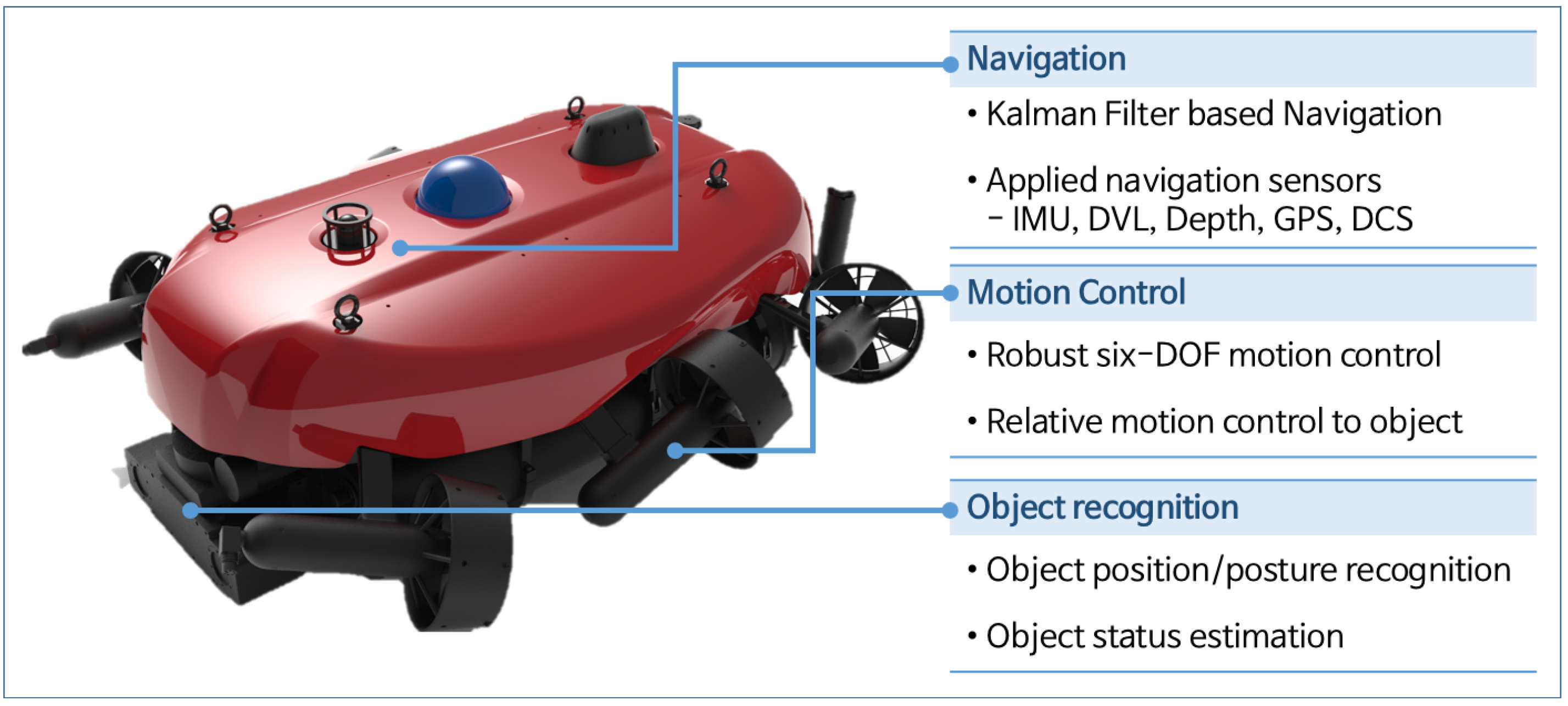
Figure 2 shows a conceptual diagram of a diver safety support vehicle currently under development in South Korea [2]. The vehicle is designed to be equipped with high-precision navigation and autonomous control technologies, along with recognition devices to detect the divers or objects. For stable hovering and motion, the vehicle employs six thrusters in a vectorized configuration, enabling six degrees-of-freedom motion. The navigation system is used to estimate the position of the body-fixed coordinate, { B } , with respect to the world coordinate, { W } . The recognition device estimates the object’s position, { C } , relative to { B } .
To control the vehicle’s motion in the relative frame { C } , it is necessary to analyze how the vehicle’s dynamics can be represented in that frame. In other words, the dynamic relationship between the state variables expressed in { C } and the control inputs expressed in { B } must be established. In this study, the vehicle dynamics in { C } are derived through a coordinate transformation of the state variables. The general dynamics of an underwater vehicle, which describe the relationship between the state variables and control inputs in the body-fixed frame { B } , can be expressed as follows [30]:
M B ν ˙ + C B ν + D B ν + g = τ B + τ E ,
where B ν = [ B v T , B ω T ] T with B v = [ u , v , w ] T and B ω = [ p , q , r ] T denotes linear and angular velocities in body-fixed coordinates; M is the inertia matrix; C is the Coriolis and centripetal forces; D is the damping terms; g is the weight and buoyancy; B τ is the control inputs in body-fixed coordinates; and τ E is the external disturbances acting on the vehicle. In the subsequent analysis, it is reasonable to assume that these disturbances remain within a finite bound, which is a common consideration in robust control formulations.
Assumption 1.
The external disturbance τ E acting on the underwater vehicle is assumed to be bounded, i.e.,
τ E τ ¯ E ,
where τ ¯ E > 0 is a known constant representing the maximum possible disturbance level. This assumption is commonly adopted in robust control formulations to ensure the feasibility of stability analysis [31].
By introducing positive definite constant matrix M ¯ , the above equations can be rearranged as follows:
M ¯ B ν ˙ + H = τ B ,
where H denotes augmented nonlinear terms defined as
H = ( M M ¯ ) B ν ˙ + C B ν + D B ν + g τ E .
In (3), the vehicle’s state variable B ν , expressed in the body-fixed frame { B } , can be represented in the object frame { C } through a coordinate transformation. To perform this transformation, the pose (i.e., position and orientation) of the moving frame { C } must be available in real time. As illustrated in Figure 2, the vehicle is equipped with an object recognition module that estimates the pose of the target object. Therefore, the following assumption is introduced.
Assumption 2.
The pose of the moving object frame { C } is assumed to be estimated in real time by the vehicle’s recognition module without significant delay.
Under this assumption, the coordinate transformation between the two frames can be formally defined, and the relationship is summarized in the following Lemma.
Lemma 1.
Let us consider a vehicle having a dynamics in (1), and that the coordinates { B } are fixed on the vehicle’s body and there is a coordinate { C } that is moved with respect to the world coordinate { W } , as depicted in Figure 1. Then, the linear and angular velocities of the vehicle in { B } , B ν = [ B v T , B ω T ] T , can be described in { C } , as follows:
C ν = B C J B ν + ζ ,
where
B C J = B C R 0 0 B C R , a n d ,
ζ = W C R W v C C ω C × C P B / C C ω C ,
and C P B / C denotes the distance vector between origins of { B } and { C } with respect to { C } , which is defined as
C P B / C = W C R ( W P B W P C ) ,
and for a vector a = [ a , b , c ] T ,
a × = 0 c b c 0 a b a 0 .
Proof. 
See Appendix A. □
By differentiating Equation (5), one can obtain the following acceleration relationship:
C ν ˙ = B C J B ν ˙ + B C J ˙ B ν + ζ ˙ ,
where
B C J ˙ = B C R ( B ω × B ω C × ) 0 0 B C R ( B ω × B ω C × ) ,
and
ζ ˙ = α 1 W C R W ω ˙ C , w i t h α 1 = W C R W v ˙ C W C R W ω C × C P B / C + 2 C ω C × W C R W v C C ω C × B C R B v + C ω C × ( C ω C × C P B / C ) .
Differentiating Equation (6a) induces Equation (10) due to the differentiation rule of a rotation matrix: B A R ˙ = B A R B ω B / A × = A ω B / A × B A R [32]. And, the detailed derivation of Equation (11) is provided in Appendix B.
By using the relationship between the state variables derived above, the vehicle dynamics that describe the vehicle’s motion in the object frame, { C } , can be obtained with respect to the control input designed in the body-fixed frame, { B } . Substituting Equation (9) into Equation (3) yields the following expression:
M ¯ B C J 1 C ν ˙ + H C = B τ ,
where
H C = H M ¯ B C J 1 B C J ˙ B ν M ¯ B C J 1 ζ ˙ ,
and
B C J 1 = C B R 0 0 C B R .
From Equations (10), (11) and (14), one can obtain B C J 1 B C J ˙ and B C J 1 ζ ˙ as follows:
B C J 1 B C J ˙ = B ω × B ω C × 0 0 B ω × B ω C × ,
B C J 1 ζ ˙ = α 2 B ω ˙ C , , w i t h α 2 = B v ˙ C + 2 B ω C × B v C B ω C × B v + B ω C · B P B / C B ω C B ω C · B ω C B P B / C .
As a result, the dynamics of the vehicle can be expressed as Equation (12), which indicates the relationship between control input in { B } and the vehicle’s motion in { C } .
Remark 1.
Note that the relationship in (5) and the dynamics in Equation (12) are for the case when { C } moves with respect to { W } . When assuming that the motion of { C } is negligible, i.e., v C = ω C = 0 , the relationship and the dynamics can be expressed in more simplified forms. In the case, ζ = 0 in Equation (6b); thus, one can obtain the following relationship.
C ν = B C J 0 B ν ,
where B C J 0 = B C J . The acceleration relationship is derived as follows:
C ν ˙ = B C J 0 B ν ˙ + B C J ˙ 0 B ν ,
where
B C J ˙ 0 = B C R B ω × 0 0 B C R B ω × .
And the dynamics can be rearranged as follows:
M ¯ B C J 0 1 C ν ˙ + H C 0 = B τ ,
where B C J 0 1 = B C J 1 , and
H C 0 = H M ¯ B C J 0 1 B C J ˙ 0 B ν ,
and
B C J 0 1 B C J ˙ 0 = B ω × 0 0 B ω × .

3. Robust Control for Tracking Trajectories in Relative Space

3.1. Design of Robust Relative Motion Controller

Using the dynamics in Equation (12), one can design the control input in { B } to track the desired trajectory in { C } , the relative space between the object and the vehicle. Based on the computed torque control, the control inputs for the dynamics in Equation (12) can be designed as follows:
B τ = H ^ C + M ¯ B C J 1 C μ ,
where C μ denotes the desired input to assign desired error dynamics designed in { C } to the controlled system. Substituting Equation (23) into Equation (12) and assuming that there is no dynamics estimation error, H ^ C = H C , yields the following desired error dynamics:
C μ C ν ˙ = 0 .
In Equation (23), the estimated values of the nonlinear dynamics, denoted as H ^ C , can be estimated using the TDE. TDE is a technique for estimating the nonlinear dynamics of vehicles using very short time-delayed values, based solely on the system’s input-output, providing a highly efficient and robust estimation method [27]. From Equations (9) and (12), the values of H ^ C can be estimated by using TDE as follows:
H ^ C = H C ( t L ) = B τ ( t L ) M ¯ B C J ( t L ) 1 C ν ˙ ( t L ) = B τ ( t L ) M ¯ B ν ˙ ( t L ) M ¯ B C J ( t L ) 1 B C J ˙ ( t L ) B ν ( t L ) M ¯ B C J ( t L ) 1 ζ ˙ ( t L ) ,
where L represents a very short time delay, typically applying the fastest time interval in the control system, which is the sampling time. Applying the above TDE to Equation (23), the controller can be derived as follows:
B τ = B τ ( t L ) M ¯ B ν ˙ ( t L ) M ¯ B C J ( t L ) 1 B C J ˙ ( t L ) B ν ( t L ) M ¯ B C J ( t L ) 1 ζ ˙ ( t L ) + M ¯ L B C J 1 C μ .
To induce second-order desired error dynamics to the controlled system, the desired input is designed as follows:
C μ = C x ¨ d + K D C x ˙ e + K P C x e ,
where K D and K P denote the derivative gain matrix and the proportional gain matrix, respectively; C x ˙ e = C ν d C ν ; C x e = [ C P e T , C R e T ] T with C P e = C P d C P B , and,
C R e = B C R B C R d T B C R B C R T B C R d 2 1 + t r [ B C R d T B C R ] .
C R e defined in Equation (28) is vectorized error from the difference between rotation matrices, which can cover large rotational error [33]. By substituting Equation (27) into the error dynamics in Equation (24) and assuming there is no dynamics estimation error, H ^ C = H C , then one can obtain the following error dynamics:
C x ¨ e + K D C x ˙ e + K P C x e = 0 .
Therefore, the proposed relative motion controller is summarized by Equations (26) and (27), which can determine the control input in { B } to track the trajectory in the relative space between the diver and the vehicle, { C } . Note that, as observed from (26), the controller generates the control inputs in { B } ; and, as shown in Equation (29), the controlled system has error dynamics in { C } , reducing the tracking error in the relative motion space.
Remark 2.
Although the TDC structure adopted in this study follows the conventional formulation, several unique challenges arise when applying it to the relative coordinate system. First, the disturbance term to be estimated by TDE in Equation (25) includes not only unmodeled dynamics and environmental disturbances but also the coupling terms generated by the motion of the moving reference frame { C } . This increases the frequency content of the equivalent disturbance τ E , requiring sufficiently small sampling intervals to ensure accurate time-delay estimation. Second, the control input in the body-fixed frame affects the relative-space dynamics through the transformation matrix B C J , which varies over time. Therefore, the estimation and compensation process of TDC must account for the time-varying transformation when reconstructing the system dynamics in the relative frame. Despite these challenges, the proposed controller maintains the same simple structure as the conventional TDC, without requiring additional adaptive parameters, because the time-varying coupling is explicitly modeled within the relative dynamic equations.
Remark 3.
Note that, when the motion of { C } is negligible, the controller in Equation (26) can be simplified as follows:
B τ = B τ ( t L ) M ¯ B ν ˙ ( t L ) M ¯ B C J 0 ( t L ) 1 B C J ˙ 0 ( t L ) B ν ( t L ) + M ¯ L B C J 0 1 C μ ,
and C ν included in C μ is calculated as Equation (17) instead of Equation (5).

3.2. Stability Anlaysis

If the TDE in Equation (25) leaves no modeling error, the proposed controller works accurately. If there is a modeling error, however, the stability and the performance can be degraded due to the modeling error. By removing the assumption of H ^ C = H C , one can re-formulate the error dynamics in Equations (24) and (29) as follows:
C μ C ν ˙ = B C J ϵ , a n d ,
C x ¨ e + K D C x ˙ e + K P C x e = B C J ϵ ,
where ϵ is the TDE error which is defined as
ϵ = M ¯ 1 ( H C H ^ C ) .
One can recognize that, from Equation (32), the TDE error affects the error dynamics as a forcing function.
For simplicity of stability analysis, the vehicle dynamics in Equation (12) with Equations (13) and (4) are described as follows:
M B C J 1 C ν ˙ + N = B τ ,
where
N = M B C J 1 B C J ˙ B ν M B C J 1 ζ ˙ + C B ν + D B ν + g τ E .
The dynamics of the TDE error, ϵ , is derived as the following lemma:
Lemma 2.
Let us consider that the underwater vehicle having dynamics in Equation (34) with Equation (35) is controlled by the relative motion controller based on the TDE in Equation (26). Then, the dynamics of the TDE error are obtained as follows:
ϵ ( t ) = ( I M ( t ) 1 M ¯ ) ϵ ( t L ) + ( I M ( t ) 1 M ¯ ) η 1 ( t ) + η 2 ( t ) ,
where
η 1 ( t ) = B C J ( t ) 1 C μ ˜ + B C J ˜ ( t ) 1 C μ ( t L ) , a n d ,
η 2 ( t ) = M ( t ) 1 N ˜ + M ˜ B C J ( t L ) 1 C ν ˙ ( t L ) ,
and ˜ = ( t ) ( t L ) .
Proof. 
See Appendix C. □
The stability of the proposed controller is analyzed by inspecting the boundedness of the TDE error, ϵ . The error dynamics in Equation (32) indicate that the tracking error, C e , has exponentially stable dynamics subject to ϵ with appropriate control gains, K D and K P . Thus, the boundedness of ϵ guarantees the BIBO stability of the proposed controller. The boundedness ϵ can be shown in a similar manner to the analysis of the control scheme based on the TDE [27,34,35]. The stability condition is derived under Assumption 1 that external disturbances are bounded, as typically adopted in robust control formulations [31].
Theorem 1.
Assume that η 1 and η 2 , in Equations (37a) and (37b) are bounded forcing functions. Then the TDE error, ϵ , having dynamics in Equation (36), is bounded if the following condition is satisfied:
| | I M ( t ) 1 M ¯ | | < 1 .
Proof. 
See Appendix D. □
Remark 4.
When the sampling time, L, is sufficiently short, as discussed in [28], the assumption of the boundedness of η in Equations (37a) and (37b) can be accepted in the practical manner. It is because η includes the dynamic variation during a sampling time, and the vehicle has continuous or piecewise continuous dynamics [30] of which variation during a sampling time can be bounded if L 0 [36]. When the sampling time is relatively long, however, the boundedness of η may not be guaranteed. In such case, the proposed conditions in Equation (38) are not sufficient for the stability, and a rigorous stability analysis with consideration of finite sampling time is required, as studied in [37].
Remark 5.
If the effects of the forcing function, η , are negligible, the stability condition in Equation (38) aligns with that of the conventional TDC as described in [16,36]. This implies that the proposed relative motion control formulation has minimal impact on the stability of the controlled system. Consequently, the gains of the proposed controller can be tuned using the methods established for the conventional TDC. If the inertial matrix, M , is known, the positive diagonal matrix, M ¯ , can be designed based on Equation (38). If M is unknown, the elements of M ¯ can be tuned by gradually increasing them from sufficiently small values until satisfactory tracking performance is achieved [27].
Remark 6.
In the implementation of TDE-based control, the design of a very short time delay L is critical to the estimation accuracy. In practice, the minimum achievable delay is limited by the control sampling interval and the computational latency of the onboard processor. When L is close to the sampling period, the estimation of the nonlinear dynamics becomes sufficiently accurate, whereas excessively reducing L may amplify sensor noise or numerical differentiation errors. In this study, L was selected equal to the control sampling interval (10 ms), which ensures reliable estimation without introducing excessive noise sensitivity. In real-world systems, potential performance degradation may arise from quantization effects, communication latency, and sensor drift. Nevertheless, previous studies [27,36] have demonstrated that the TDE framework preserves robustness as long as the delay remains within one sampling interval. Therefore, the proposed controller is practically realizable using standard real-time processors without additional hardware compensation.

4. Simulation

In this section, the performance of the proposed controller is verified through simulations. The simulation scenario reproduces the situation conceptually illustrated in Figure 1, where an underwater vehicle inspects a floating and moving object from multiple directions. The target object is assumed to move due to ocean currents and surface waves. Specifically, it moves horizontally in the 45 ° direction at a velocity of 0.2 m/s under the influence of current flow, while it sinks vertically at 0.1 m/s due to its own weight. In addition, it oscillates vertically with a wave-induced motion of amplitude 0.2 m and frequency 0.1 Hz. Under wave disturbances, the object exhibits roll, pitch, and yaw oscillations with an amplitude of 0.1 rad and a frequency of 0.1 Hz.
To investigate the moving object from various directions, the vehicle is designed to maintain a 1 m height difference from the object while following a petal-shaped trajectory around it. The desired relative motion of the vehicle with respect to the object is illustrated in Figure 3.
The dynamics model of the BlueROV2 is used for the simulation [38]. The initial position of the vehicle is set to W [ x , y , z , r o l l , p i t c h , y a w ] T = W [ 5.0 , 0 , 1.0 , 0 , 0 , π / 2 ] T , and the initial position of the object is set to W [ 0 , 0 , 2.0 , 0 , 0 , π / 2 ] T .
Through the simulation of the above mission scenario, the performance of the proposed controller was verified. The proposed controller is defined by Equations (26) and (27). The control gains are designed as follows. The derivative and proportional gains are set to K D = 12.0 I and K P = 9.0 I , which yield the error dynamics in Equation (29) with a natural frequency of 3.0 rad / s and a damping ratio of 2.0 . As explained in Remark 5, the positive definite matrix M ¯ = d i a g [ 10.0 , 10.0 , 10.0 , 0.3 , 0.3 , 0.3 ] T was tuned by gradually increasing its diagonal elements from sufficiently small values until satisfactory tracking performance was achieved. For performance comparison, an additional controller with the same gain settings as the proposed controller was designed without considering the motion of the relative frame { C } , as described in Remark 3.
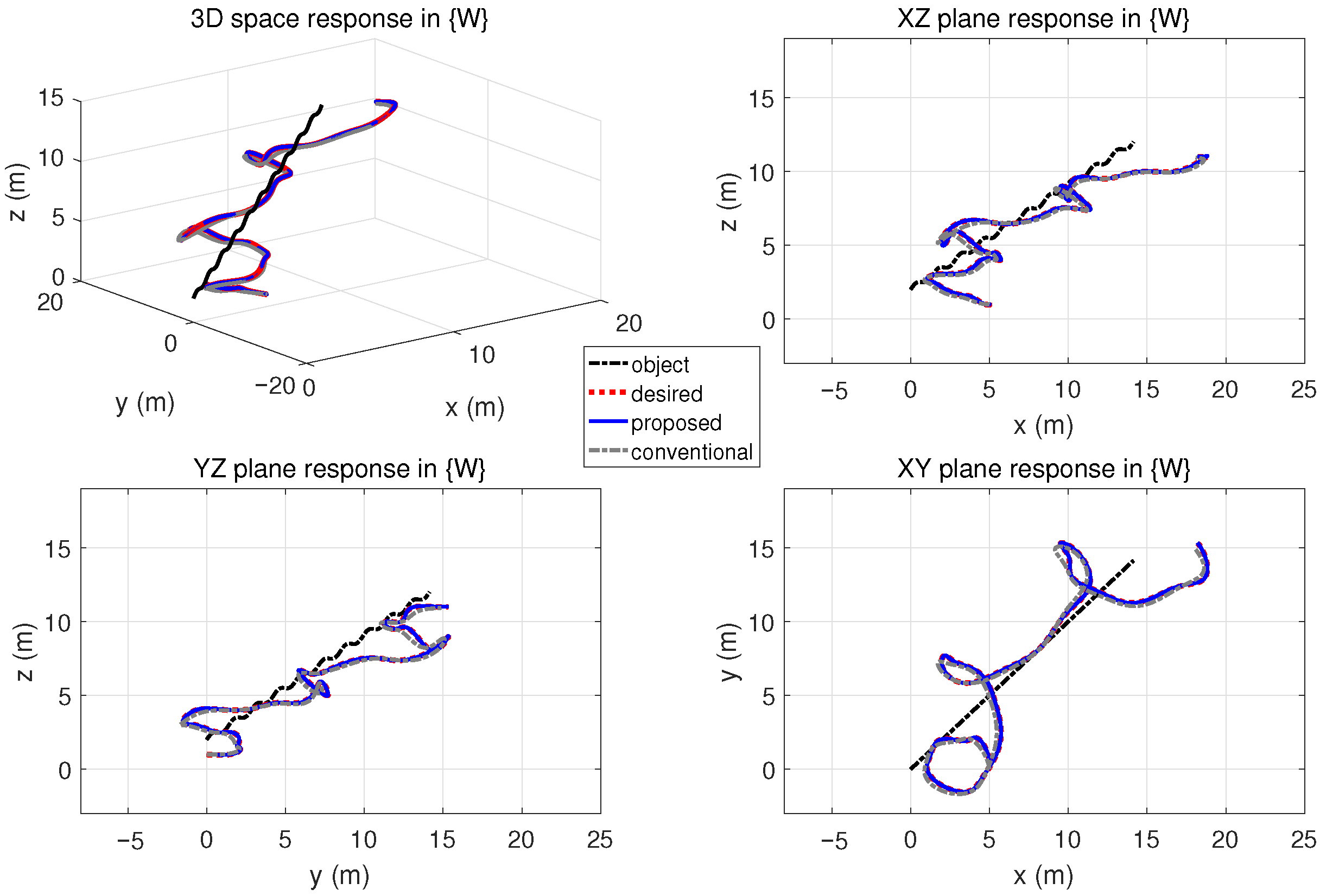
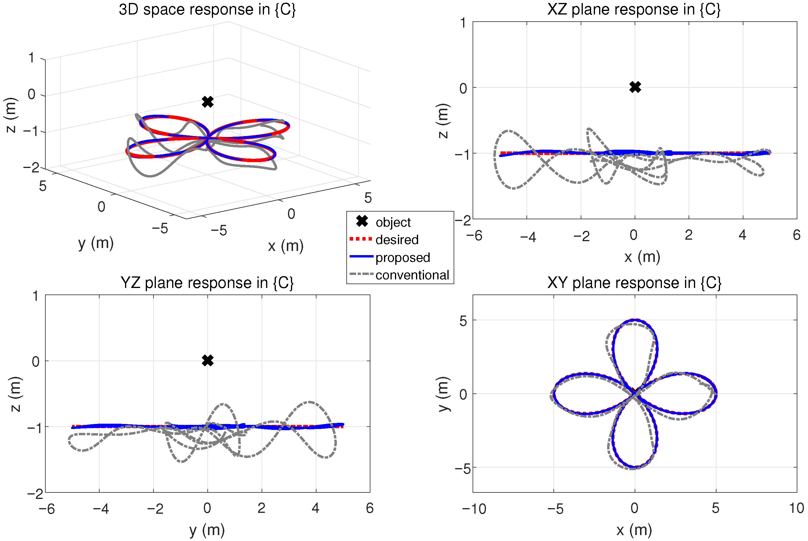
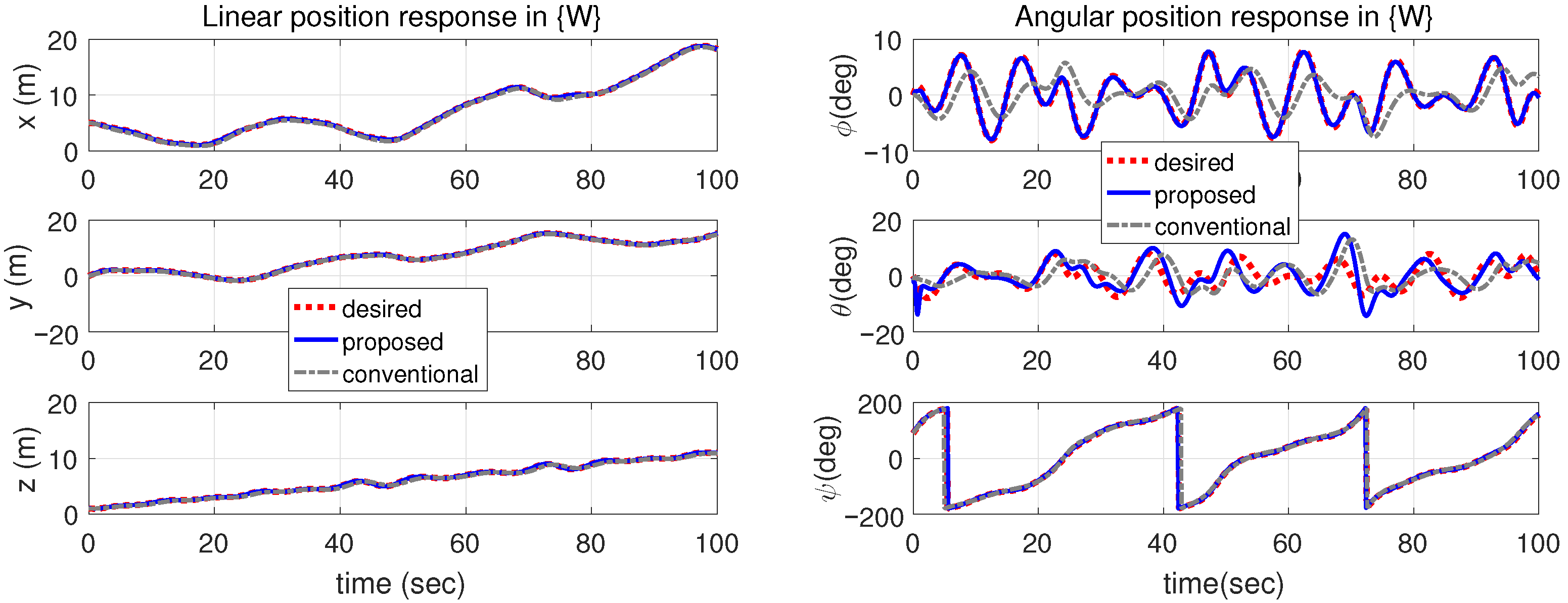
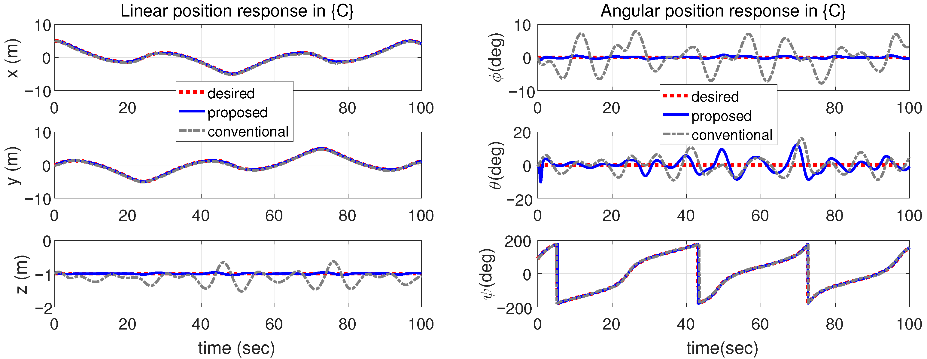
The simulation results are presented in Figure 4, Figure 5, Figure 6, Figure 7, Figure 8 and Figure 9, and the root mean square errors are summarized in Table 1. Figure 4 shows the motion of the object, the reference trajectories, and the control responses of the vehicle in the world frame, { W } . It can be observed that the object moves according to the predefined current and wave conditions, while the vehicle successfully follows the object by moving around it. The trajectory tracking performance of the controller can be examined in Figure 5, which illustrates the reference and response trajectories in the object frame, { C } . The vehicle maintains a consistent vertical distance of approximately 1 m and follows the petal-shaped path as designed. The proposed controller accurately maintains the desired 1 m depth difference and achieves precise trajectory tracking, whereas the comparative controller exhibits larger depth errors and less accurate tracking. The quantitative performance improvement is also confirmed in Table 1, where the proposed controller achieves translational tracking errors reduced to approximately 4.97 7.27 % of those from the comparative controller. In terms of orientation errors, the proposed method shows comparable or superior tracking performance. Figure 6 and Figure 7 present the time responses of the simulation results in the world frame, { W } , and object frame, { C } , respectively, demonstrating the trajectory tracking capability of the proposed controller in the relative space. Figure 8 illustrates the control inputs for both controllers. It is observed that, despite the superior tracking performance, the proposed controller applies similar control inputs to those of the comparative controller, indicating that no excessive actuation effort is required.
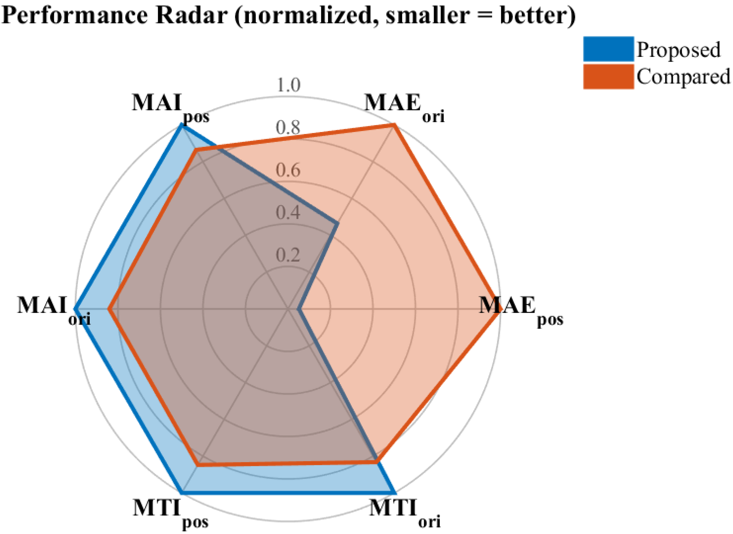
To quantitatively evaluate the control performance of the proposed method in both translational and rotational motions, three evaluation indicators were introduced: the Mean Absolute Error (MAE), the Mean Absolute Input (MAI), and the Mean Torque Increment (MTI) [39]. Each metric was computed separately for position and orientation components, denoted as MAE p o s , MAE o r i , MAI p o s , MAI o r i , MTI p o s , and MTI o r i . These indicators evaluate tracking accuracy, control effort, and input smoothness, respectively.
MAE p o s = 1 T 0 T e p o s ( t ) 2 d t , MAE o r i = 1 T 0 T θ e ( t ) d t ,
MAI p o s = 1 T 0 T F ( t ) 2 d t , MAI o r i = 1 T 0 T F R ( t ) 2 d t ,
MTI p o s = 1 T 0 T F ˙ ( t ) 2 d t , MTI o r i = 1 T 0 T F ˙ R ( t ) 2 d t ,
where e p o s ( t ) denotes the position tracking error in { C } , F ( t ) and F R ( t ) are the control force and control torque vectors in { B } , respectively, and θ e ( t ) represents the rotational deviation between the desired and actual orientations in { C } . The orientation error θ e ( t ) was obtained from the rotation matrices as
θ e ( t ) = cos 1 tr ( R d T R ) 1 2 ,
which provides a rotation-invariant measure of the angular difference. All metrics were normalized by their maximum values for consistent comparison among different controllers. Figure 9 presents the normalized radar chart of these six performance metrics. The proposed controller achieved a 94.8% reduction in MAE p o s and a 53.6% reduction in MAE o r i while maintaining moderate MAI and MTI values, demonstrating both high tracking precision and smooth control performance.
The simulation results confirm that the proposed control scheme effectively follows the trajectory defined in the relative coordinate frame between the object and the vehicle, even when the relative space moves with respect to the world coordinate frame.

5. Conclusions and Future Works

This study presents the design of a robust controller for underwater vehicles that track trajectories in the relative coordinate frame. In particular, the controller is formulated to maintain precise tracking performance even when the relative frame moves with respect to the world coordinate frame. To this end, a coordinate transformation of the vehicle’s state variables was introduced to derive the dynamic model that represents the vehicle’s motion in the relative space with respect to control inputs applied in the body-fixed frame. Based on the transformed dynamics, a robust control law was developed to achieve accurate trajectory tracking in the relative space. The TDC was employed to ensure both structural simplicity and robustness of the control law. The stability of the proposed controller was analyzed theoretically, and the resulting stability condition was found to be consistent with that of the conventional TDC. Consequently, the controller design and gain-tuning process can be performed in a manner similar to that of standard TDC approaches. The analysis clarified that, although the TDC structure itself remains unchanged, the delay estimation process must handle additional coupling terms arising from reference-frame motion. These terms are analytically modeled in the relative dynamics, allowing accurate disturbance estimation without introducing extra adaptive parameters.
Through simulations of an inspection mission involving a floating object, the proposed controller was verified to accurately track the desired trajectory defined in the relative space between the object and the vehicle. Quantitative simulation results further verified the superiority of the proposed controller. When compared with a conventional controller that does not account for the motion of the relative frame, the proposed method achieved a 94.8% reduction in position tracking error and a 53.6% reduction in orientation tracking error, while maintaining smooth control effort under wave-induced reference motion. These results confirm that explicitly modeling the dynamics of the moving reference frame enhances both tracking accuracy and robustness in relative-space control.
Beyond the implementation and verification, the theoretical contributions of this study can be summarized as follows. First, a generalized dynamic model of the vehicle was newly derived in the relative coordinate system, where the reference frame is allowed to move and rotate over time. This provides a consistent mathematical representation of the vehicle–reference coupling, which has not been explicitly considered in previous relative-space formulations. Second, the stability of the proposed controller was analyzed in the relative-space domain by examining the boundedness of the TDE error dynamics. This analysis extends the conventional stability results of TDC to dynamic reference conditions, ensuring BIBO stability of the relative error system. Finally, a new relative error system was formulated to capture the dynamic coupling between the vehicle and the moving reference, allowing the TDC framework to be consistently applied in the relative coordinate domain. Together, these contributions establish a generalized and robust theoretical foundation for relative space control of underwater vehicles.
Future work will focus on experimental validation of the proposed control scheme. A prototype of the diver-supporting vehicle, shown in Figure 2, has been developed, and functional control tests are currently in progress. Experimental trials are expected to be conducted in the near future.

Author Contributions

Conceptualization, G.R.C.; methodology, G.R.C.; software, G.R.C., H.K., H.-S.J.; validation, G.R.C., M.-G.K., S.J.; formal analysis, G.R.C., C.B.; investigation, G.R.C., S.P.; resources, G.R.C., S.P., S.J.; data curation, G.R.C., J.-H.L.; writing—original draft preparation, G.R.C.; writing—review and editing, G.R.C.; visualization, G.R.C.; supervision, G.R.C.; projection administration, G.R.C.; funding acquisition, G.R.C. All authors have read and agreed to the published version of the manuscript.

Funding

This research was supported by the development of standard manufacturing technology for marine leisure vessels and safety support robots for underwater leisure activities of the Korea Institute of Marine Science and Technology Promotion (KIMST) and funded by the Ministry of Oceans and Fisheries (RS-2022-KS221668).

Data Availability Statement

The original contributions presented in this study are included in the article. Further inquiries can be directed to the corresponding author.

Conflicts of Interest

The authors declare no conflicts of interest.

Nomenclature

List of symbols and definitions.
SymbolDescription
{ W } World coordinate frame
{ B } Body-fixed coordinate frame of the vehicle
{ C } Object (relative) coordinate frame
B A R Rotation matrix from frame { B } to { A }
A v Linear velocity of { B } expressed in { A }
A ω Angular velocity of { B } expressed in { A }
M Inertia matrix of the underwater vehicle
C Coriolis and centripetal matrix
D Hydrodynamic damping matrix
g Restoring forces and moments (gravity and buoyancy)
B τ Control input vector in { B } frame
τ E Environmental disturbance vector
B ν = [ B v T , B ω T ] T Linear and angular velocity vector in { B }
C ν Linear and angular velocity vector expressed in { C }
B C J Adjoint transformation (Jacobian) from { B } to { C }
ζ Additional velocity term due to motion of { C } (Equation (5))
C P B / C Position of { B } origin w.r.t. { C }
v C , ω C Linear and angular velocities of { C } w.r.t. { W }
H Augmented nonlinear term (Equation (3))
H C Nonlinear term transformed into { C } (Equation (12))
H ^ C Estimated nonlinear term via TDE
LSampling interval (time delay)
μ C Desired input in relative frame { C }
K P , K D Proportional / derivative gain matrices
C x e , C x ˙ e Position / velocity error in { C }
C R e Rotational error vector (Equation (28))
ϵ Time-delay estimation (TDE) error
η 1 , η 2 Forcing functions in TDE error dynamics
I Identity matrix
T Transpose of •

Abbreviations

The following abbreviations are used in this manuscript:
AUVAutonomous Underwater Vehicle
TDCTime Delay Control
TDETime Delay Estimation
BIBOBounded Input Bounded Output

Appendix A. Proof of Lemma 1

From (7), the linear velocity is derived as follows.
C v = C P ˙ B / C = B C R B v W C R W v C C ω C × C P B / C .
The rotational velocity of the vehicle with respect to { C } is obtained as follows.
C ω = W C R ( B W R B ω W ω C ) = B C R B ω C ω C
By considering the linear velocity in (A1) and the angular velocity in (A2), one can obtain the relationship in (5).

Appendix B. Proof of (11)

Let us consider ζ = [ v ζ ; ω ζ ] in (6b). The derivatives of the elements of ζ can be obtained as follows:
v ˙ ζ = W C R ˙ W v C W C R W v ˙ C C ω ˙ C × C P B / C C ω C × C P ˙ B / C
W C R ˙ and C P ˙ B / C in (A3) can be derived as follows.
W C R ˙ = C ω W × W C R = C ω C × W C R
C P ˙ B / C = d d t W C R ( W P B W P C ) = C ω C × C P B / C + B C R W v W C R W v C
Substituting (A4a) and (A4b) into (A3) yields α 1 in (11). The derivative of the rotation term in (6b), ω ζ = C ω C , is derived as follows.
ω ˙ ζ = d d t W C R W ω C = C ω C × W C R W ω ˙ C W C R W ω ˙ C = W C R W ω ˙ C
because, C ω C × W C R W ω ˙ C = C ω C × C ω C = 0 .

Appendix C. Proof of Lemma 2

Multiplying (32) by M and substituting (34), we obtain the following:
M ( t ) ϵ ( t ) = M B C J ( t ) 1 C μ ( t ) M B C J ( t ) 1 C ν ˙ ( t ) = M B C J ( t ) 1 C μ ( t ) + N ( t ) B τ ( t )
From (12) and (34), one can find that H C can be rearranged as follows:
H C = ( M M ¯ ) B C J 1 C ν ˙ + N
Using H ^ C ( t ) = H C ( t L ) from (25) and considering (A7), one can rearrange the control input in (23) as follows:
B τ ( t ) = H C ( t L ) + M ¯ B C J ( t ) 1 C μ ( t ) = ( M ( t L ) M ¯ ) B C J ( t L ) 1 C ν ˙ ( t L ) + N ( t L ) + M ¯ B C J ( t ) 1 C μ ( t )
Substituting (A8) into (36) yields the following:
M ( t ) ϵ ( t ) = ( M ( t ) M ¯ ) B C J ( t L ) 1 C ν ˙ ( t L ) + M ˜ B C J ( t L ) 1 C ν ˙ ( t L ) + ( M M ¯ ) B C J ( t ) 1 C μ ( t ) + N ˜
From (31), C ν ˙ ( t L ) = C μ ( t L ) B C J ( t L ) ϵ ( t L ) holds; by substituting this equation into (A9), one can obtain the following:
M ( t ) ϵ ( t ) = ( M ( t ) M ¯ ) ϵ ( t L ) ( M ( t ) M ¯ ) B C J ( t L ) 1 C μ ( t L ) + M ˜ B C J ( t L ) 1 C ν ˙ ( t L ) + ( M M ¯ ) B C J ( t ) 1 C μ ( t ) + N ˜ = ( M ( t ) M ¯ ) ϵ ( t L ) + ( M ( t ) M ¯ ) B C J ( t ) 1 C μ ˜ + ( M ( t ) M ¯ ) B C J ˜ 1 C μ ( t L ) + M ˜ B C J ( t L ) 1 C ν ˙ ( t L ) + N ˜
By multiplying (A10) by M ( t ) 1 , one can obtain the error dynamics of the TDE error as (36) with (37a) and (37b).

Appendix D. Proof of Theorem 1

The dynamics of the TDE error in (36) can be described in discrete time domain by setting t = k L , as follows:
ϵ ( k ) = ( I M ( k ) 1 M ¯ ) ϵ ( k 1 ) + ( I M ( k ) 1 M ¯ ) η 1 ( k ) + η 2 ( k )
The condition | | I M ( t ) 1 M ¯ | | < 1 in (38) implies that the eigenvalues of (A11), the first difference equation, remains in unit circle. Thus, (A11) is asymptotically stable, i.e., ϵ is bounded when the forcing functions, η 1 and η 2 , are bounded [36].

References

  1. Kartal, S.K.; Cantekin, R.F. Autonomous underwater pipe damage detection positioning and pipe line tracking experiment with unmanned underwater vehicle. J. Mar. Sci. Eng. 2024, 12, 2002. [Google Scholar] [CrossRef]
  2. Kang, H.; Cho, G.R.; Jin, H.; Kim, M.G.; Li, J.H.; Jin, S.; Lee, J.; Min, J. Robot-Based Diver Safety Support Scenario and Concept Design for NADIA. J. Ocean Eng. Technol. 2025, 39, 235–247. [Google Scholar] [CrossRef]
  3. Cho, G.R.; Kang, H.; Kim, M.G.; Park, S.; Jin, H.; Jin, S. Operational Space Fomulation of Time Delay Control for Underwater Vehicles and its Extension to Diver Guidance. In Proceedings of the 2025 IEEE Underwater Technology (UT), Taipei, Taiwan, 2–5 March 2025; pp. 1–8. [Google Scholar]
  4. Yang, Y.; Xiao, Y.; Li, T. A survey of autonomous underwater vehicle formation: Performance, formation control, and communication capability. IEEE Commun. Surv. Tutor. 2021, 23, 815–841. [Google Scholar] [CrossRef]
  5. Yan, T.; Xu, Z.; Yang, S.X.; Gadsden, S.A. Formation control of multiple autonomous underwater vehicles: A review. Intell. Robot. 2023, 3, 1–22. [Google Scholar] [CrossRef]
  6. Zheng, R.; Song, T.; Sun, Q.; Guo, J. Review on underwater docking technology of AUV. Chin. J. Ship Res. 2018, 13, 43–49. [Google Scholar]
  7. Sun, Y.; Ran, X.; Cao, J.; Li, Y. Deep submergence rescue vehicle docking based on parameter adaptive control with acoustic and visual guidance. Int. J. Adv. Robot. Syst. 2020, 17, 1729881420919955. [Google Scholar] [CrossRef]
  8. Li, D.-j.; Chen, Y.-h.; Shi, J.-g.; Yang, C.-j. Autonomous underwater vehicle docking system for cabled ocean observatory network. Ocean Eng. 2015, 109, 127–134. [Google Scholar] [CrossRef]
  9. Somerton, D.A.; Williams, K.; Campbell, M.D. Quantifying the behavior of fish in response to a moving camera vehicle by using benthic stereo cameras and target tracking. Fish. Bull. 2017, 115, 343–354. [Google Scholar] [CrossRef]
  10. Neettiyath, U.; Thondiyath, A. Dynamic formations of autonomous underwater vehicles using state estimation. In Proceedings of the Conference on Advances In Robotics, Pune, India, 4–6 July 2013; pp. 1–6. [Google Scholar]
  11. Zheng, L.; Ma, Y.; Yu, H.; Tang, Y. Multicooperation of Turtle-inspired amphibious spherical robots. Sci. Rep. 2025, 15, 2932. [Google Scholar] [CrossRef]
  12. Furukawa, T.; Matsuda, T. A Positioning Method Based on Path Control of Multiple Autonomous Underwater Vehicles. In Proceedings of the OCEANS 2024-Singapore, Singapore, 15–18 April 2024; pp. 1–5. [Google Scholar]
  13. García-Valdovinos, L.G.; Salgado-Jiménez, T.; Bandala-Sánchez, M.; Nava-Balanzar, L.; Hernández-Alvarado, R.; Cruz-Ledesma, J.A. Modelling, design and robust control of a remotely operated underwater vehicle. Int. J. Adv. Robot. Syst. 2014, 11, 1. [Google Scholar] [CrossRef]
  14. Heshmati-Alamdari, S.; Karras, G.C.; Marantos, P.; Kyriakopoulos, K.J. A robust predictive control approach for underwater robotic vehicles. IEEE Trans. Control Syst. Technol. 2019, 28, 2352–2363. [Google Scholar] [CrossRef]
  15. Heshmati-Alamdari, S.; Nikou, A.; Dimarogonas, D.V. Robust trajectory tracking control for underactuated autonomous underwater vehicles in uncertain environments. IEEE Trans. Autom. Sci. Eng. 2020, 18, 1288–1301. [Google Scholar] [CrossRef]
  16. Kumar, R.P.; Dasgupta, A.; Kumar, C. Robust trajectory control of underwater vehicles using time delay control law. Ocean Eng. 2007, 34, 842–849. [Google Scholar] [CrossRef]
  17. Kumar, R.; Kumar, C.; Sen, D.; Dasgupta, A. Discrete time-delay control of an autonomous underwater vehicle: Theory and experimental results. Ocean Eng. 2009, 36, 74–81. [Google Scholar] [CrossRef]
  18. Kim, J.; Joe, H.; Yu, S.c.; Lee, J.S.; Kim, M. Time-delay controller design for position control of autonomous underwater vehicle under disturbances. IEEE Trans. Ind. Electron. 2016, 63, 1052–1061. [Google Scholar] [CrossRef]
  19. Li, J.; Zhu, G.; Lu, J.; Chen, C. FTILOS-based self-triggered adaptive neural path following control for 4DOF underactuated unmanned surface vehicles. Ocean Eng. 2024, 295, 116947. [Google Scholar] [CrossRef]
  20. Zhu, G.; Li, J.; Ma, Y.; Hu, S. FT-ILOS-based adaptive fuzzy path following of USVs under input saturation via parallel-self-triggered approach. IEEE J. Ocean. Eng. 2025, 50, 2744–2755. [Google Scholar] [CrossRef]
  21. Liu, J.; Yu, F.; He, B.; Soares, C.G. A review of underwater docking and charging technology for autonomous vehicles. Ocean Eng. 2024, 297, 117154. [Google Scholar] [CrossRef]
  22. Zhang, Y.; Wang, Q.; Shen, Y.; Dai, N.; He, B. Multi-AUV cooperative control and autonomous obstacle avoidance study. Ocean Eng. 2024, 304, 117634. [Google Scholar] [CrossRef]
  23. Ni, T.; Sima, C.; Zhang, W.; Wang, J.; Guo, J.; Zhang, L. Vision-based underwater docking guidance and positioning: Enhancing detection with YOLO-D. J. Mar. Sci. Eng. 2025, 13, 102. [Google Scholar] [CrossRef]
  24. Chen, B.; Hu, J.; Ghosh, B.K. Finite-time coordination controls for multiple autonomous underwater vehicle systems. Eng. Rep. 2024, 6, e12804. [Google Scholar] [CrossRef]
  25. Youcef-Toumi, K.; Ito, O. A time delay controller for systems with unknown dynamics. J. Dyn. Syst. Meas. Control 1990, 112, 133–142. [Google Scholar] [CrossRef]
  26. Hsia, T.; Gao, L. Robot manipulator control using decentralized linear time-invariant time-delayed joint controllers. In Proceedings of the IEEE International Conference on Robotics and Automation, Cincinnati, OH, USA, 13–18 May 1990; pp. 2070–2075. [Google Scholar]
  27. Cho, G.R.; Chang, P.H.; Park, S.H.; Jin, M. Robust tracking under nonlinear friction using time-delay control with internal model. IEEE Trans. Control Syst. Technol. 2009, 17, 1406–1414. [Google Scholar]
  28. Cho, G.R.; Li, J.H.; Park, D.; Jung, J.H. Robust trajectory tracking of autonomous underwater vehicles using back-stepping control and time delay estimation. Ocean Eng. 2020, 201, 107131. [Google Scholar] [CrossRef]
  29. Cho, G.R.; Kang, H.; Kim, M.G.; Lee, M.J.; Li, J.H.; Kim, H.; Lee, H.; Lee, G. An Experimental Study on Trajectory Tracking Control of Torpedo-like AUVs Using Coupled Error Dynamics. J. Mar. Sci. Eng. 2023, 11, 1334. [Google Scholar] [CrossRef]
  30. Fossen, T.I. Guidance and Control of Ocean Vehicles; John Wiley & Sons Inc.: Hoboken, NJ, USA, 1994. [Google Scholar]
  31. Zhang, G.; Xing, Y.; Zhang, W.; Li, J. Prescribed Performance Control for USV-UAV via a Robust Bounded Compensating Technique. IEEE Trans. Control Netw. Syst. 2025, 12, 2289–2299. [Google Scholar] [CrossRef]
  32. Marani, G.; Yuh, J. Introduction to Autonomous Manipulation. Case Study with an Underwater Robot, SAUVIM; Springer: Berlin/Heidelberg, Germany, 2014; Volume 102. [Google Scholar]
  33. Lee, T. Exponential stability of an attitude tracking control system on SO(3) for large-angle rotational maneuvers. Syst. Control Lett. 2012, 61, 231–237. [Google Scholar] [CrossRef]
  34. Jung, S.; Hsia, T.C.; Bonitz, R.G. Force tracking impedance control of robot manipulators under unknown environment. IEEE Trans. Control Syst. Technol. 2004, 12, 474–483. [Google Scholar] [CrossRef]
  35. Hsia, T. Simple robust schemes for cartesian space control of robot manipulators. Int. J. Robot. Autom. 1994, 9, 167–174. [Google Scholar]
  36. Jin, M.; Lee, J.; Chang, P.H.; Choi, C. Practical nonsingular terminal sliding-mode control of robot manipulators for high-accuracy tracking control. IEEE Trans. Ind. Electron. 2009, 56, 3593–3601. [Google Scholar]
  37. Jung, J.; Chang, P.; Stefanov, D. Discretisation method and stability criteria for non-linear systems under discrete-time time delay control. IET Control Theory Appl. 2011, 5, 1264–1276. [Google Scholar] [CrossRef]
  38. Wu, C.J. 6-Dof Modelling and Control of a Remotely Operated Vehicle. Ph.D. Thesis, College of Science and Engineering, Flinders University, Adelaide, Australia, 2018. [Google Scholar]
  39. Zhang, G.; Sun, Z.; Li, J.; Huang, J.; Qiu, B. Iterative learning control for path-following of ASV with the ice floes auto-select avoidance mechanism. IEEE Trans. Intell. Transp. Syst. 2025, 26, 13927–13938. [Google Scholar] [CrossRef]
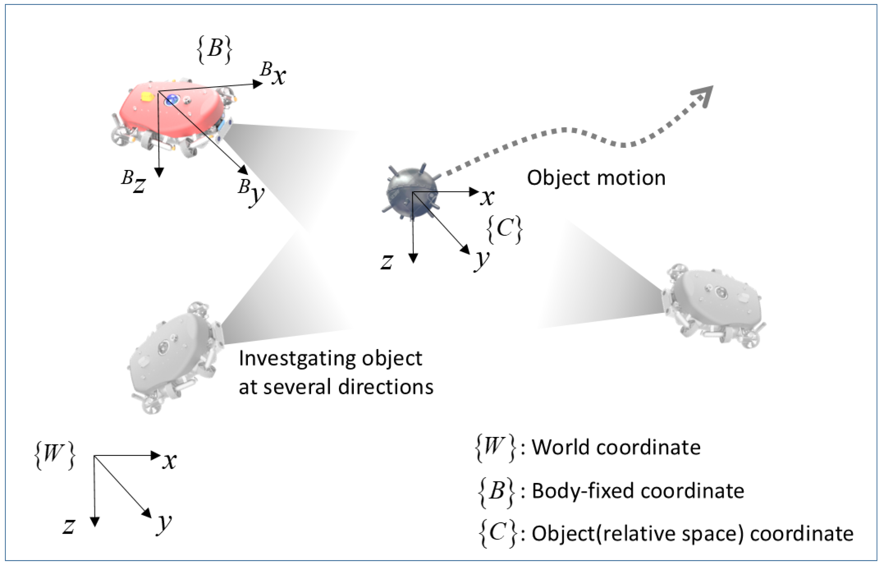
Figure 1. Coordinate system in diver guidance.
Jmse 13 02214 g001
Figure 2. Underwater vehicle for diver assistance.
Jmse 13 02214 g002
Figure 3. Desired trajectory of XY plane motion in {C}.
Jmse 13 02214 g003
Figure 4. Simulation results: 3D plot in {W}.
Jmse 13 02214 g004
Figure 5. Simulation results: 3D plot in {C}.
Jmse 13 02214 g005
Figure 6. Simulation results: Time response in {W}.
Jmse 13 02214 g006
Figure 7. Simulation results: Time response in {C}.
Jmse 13 02214 g007
Figure 8. Simulation results: control input of proposed and convetional controllers.
Jmse 13 02214 g008
Figure 9. Simulation results: comparision of MAE, MAI, MTI.
Jmse 13 02214 g009
Table 1. Root mean square errors in {C}.
ControllerxyzRollPitchYaw
① Proposed (mm, deg)10.913.616.00.2863.8730.709
② Compared (mm, deg)219.3220.4220.03.8984.9113.729
①/② × 100(%)4.976.177.277.3378.8519.02
Disclaimer/Publisher’s Note: The statements, opinions and data contained in all publications are solely those of the individual author(s) and contributor(s) and not of MDPI and/or the editor(s). MDPI and/or the editor(s) disclaim responsibility for any injury to people or property resulting from any ideas, methods, instructions or products referred to in the content.