Article

Study on Cyclic Tensile Shakedown Behaviour of Flexible Risers Considering Winding Process

1
School of Chemical Engineering, Ocean and Life Sciences, Dalian University of Technology, Panjin 124221, China
2
VH-Marinetech Co., Ltd., Shenyang 110023, China
3
Faculty of Economics and Management, Dalian University of Technology, Dalian 116024, China
*
Author to whom correspondence should be addressed.
J. Mar. Sci. Eng. 2025, 13(11), 2186; https://doi.org/10.3390/jmse13112186
Submission received: 22 October 2025 / Revised: 5 November 2025 / Accepted: 11 November 2025 / Published: 18 November 2025
(This article belongs to the Special Issue Advanced Research in Flexible Riser and Pipelines)

Abstract

Flexible risers are subjected to significant tensile loads during manufacturing, installation, and in-service phases, and they experience multiple cyclic tensile loads throughout their entire service life. Whether the armour wires can achieve shakedown under cyclic tensile loads remains an open question to be investigated. In this study, first, the winding process of the tensile armour layers was explored, and the residual stress distribution in the cross-section of the armour wires after the winding process was obtained. Subsequently, a numerical simulation model of the flexible riser that considers residual stress was established based on the ABAQUS 2021 software to study the shakedown behaviour of the flexible riser under cyclic tensile loads. The results show that, during the initial loading–unloading process of the example pipe, the stress in the armour wire cross-section undergoes obvious redistribution. When cyclic loading is applied with a tensile force range of 0–16.1 kN, the armour wire cross-section tends to reach a shakedown state as the number of loading cycles increases. However, when cyclic loading is applied with a tensile force range of 0–30.2 kN, the strain of the armour wire cross-section gradually increases with each loading–unloading cycle, thus exhibiting a ratcheting effect. The cyclic tensile shakedown prediction model proposed in this study can provide a reference for the design of armour layers in deepwater flexible risers.

1. Introduction

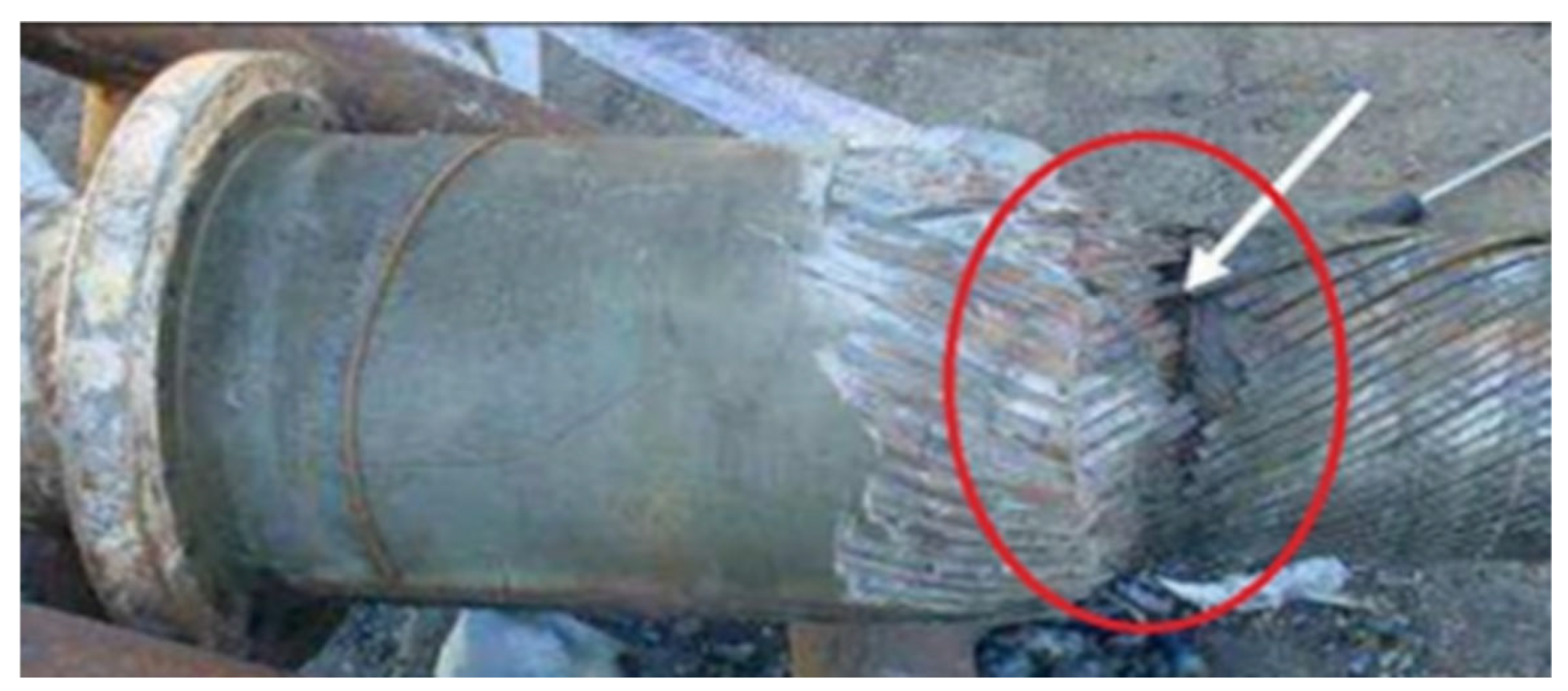
Flexible risers are critical equipment connecting subsea wellheads to upper floating structures. During their in-service operation, they bear tensile loads induced by self-weight, which increase as the application water depth increases. In marine engineering applications, deepwater flexible risers are subjected to complex dynamic loads over long-term service. Due to the uncertainty of the marine environment, the periodic motion of waves and currents causes the risers to undergo reciprocating tensile and bending deformations; cyclic tensile loads, in particular, are among the key factors affecting the risers’ service performance. Additionally, during the installation and maintenance of risers, operations such as traction and dragging also impose cyclic tensile loads on the structure. These cyclic tensile loads under actual working conditions pose severe challenges to the mechanical properties of the armour wire layers. Figure 1 shows the typical structure of a flexible riser, where the tensile armour layer bears the majority of the pipeline’s tensile load. A typical deepwater flexible riser adopts a multi-layer composite structure design, with each layer working synergistically to meet multiple functional requirements including sealing, pressure resistance, tensile resistance, wear resistance, and corrosion resistance. Among these layers, the tensile armour layer is a core load-bearing component specifically designed to bear most of the axial tensile load of the pipeline. It is usually composed of multiple layers of high-strength steel wires wound helically at a specific angle, and its mechanical properties directly determine the overall tensile strength and fatigue life of the riser. The winding process of tensile armour wires itself has a significant impact on their final performance. During this process, the steel wires are wound onto a moving mandrel via a high-speed rotating pay-off reel. While being wound, the steel wires are simultaneously subjected to tensile, bending, and torsional loads. A key characteristic is that after winding is completed, clamps and pipe end joints are usually installed directly without an unloading process being performed. This causes the internal forces exerted on the steel wire cross-section during winding—especially the stresses induced by tension and torsion—to be partially retained inside the wires, thereby forming pre-tightening forces from the processing stage. This residual stress state, combined with complex external cyclic tensile loads during service, profoundly affects the long-term mechanical behaviour and tensile failure mode of the armour layer and even the entire flexible riser. The tensile fracture failure process is shown in Figure 2.
In the research on the tensile bearing capacity of flexible risers, Knapp [1,2,3] conducted an in-depth analysis of the stress–displacement relationship of helically wound armoured cables under tensile and torsional loads. The study considered the material nonlinearity and geometric nonlinearity under large deformation conditions and provided a nonlinear solution based on numerical methods. Meanwhile, through a linear simplification algorithm, the stiffness matrix of helically wound armoured cables under combined tensile and torsional loads was derived, and the torsional equilibrium condition was established accordingly. Lanteigne et al. [4] further considered the coupling effect of helically wound armoured cables under tensile, bending, and torsional loads and proposed a stiffness matrix expression for the combined mechanical behaviour. LeClair et al. [5] put forward a method to predict the response of a single helically wound structure under tensile, bending, torsional loads, and frictional forces. Jolicoeur et al. [6] systematically summarized the existing prediction models for the mechanical behaviour of helically wound steel wires under axisymmetric loads, organized these models into a standardized form, obtained the results of each theoretical model through numerical methods, and compared them with experimental results. Witz et al. [7] derived the governing equations for flexible structures such as flexible pipes, umbilicals, and marine cables, and solved the load–displacement relationship under combined tensile and torsional conditions. It is worth noting that there is a difference in stress analysis between flexible pipes and cables—the stress analysis of cables does not involve internal pressure loads. Custodio et al. [8] proposed the response analysis equations and their solution methods for umbilicals and unbonded flexible pipes under tensile and torsional loads combined with internal and external pressures. Ramos et al. [9] studied the tensile-torsional performance of unbonded flexible pipes under internal and external pressure loads, proposed a linear solution for the stress and strain of each layer of the pipe, and verified the calculation results of the theoretical method through numerical and experimental means. Yue, Tang, and other researchers [10], respectively, proposed analytical models to predict the axial tensile stiffness of flexible pipes and umbilicals based on their radial contraction deformation and verified the correctness of the models by combining them with pipe tensile experiments. Xiang et al. [11] developed a new model to describe the response characteristics of multi-strand steel wire ropes under axial tension and axial torque. Francesco et al. [12] proposed a new analytical model to study the elastoplastic behaviour of metal helical wires under axial torsional loads. However, all of the above studies on tensile bearing capacity focus on single tension, and none involve cyclic tension, which is related to the issue of shakedown behaviour.
In the field of shakedown theory and experimental research, many scholars have carried out in-depth mechanical analyses. The German scholar Bleich [13] first proposed the concept of adaptability of truss structures under cyclic loads, and then Dr. Melan [14] extended it to three-dimensional ideally elastoplastic structures. The classical lower bound theorem of shakedown proposed by Melan [15] and the kinematic shakedown theorem proposed by Koiter [16] jointly laid the foundation of the shakedown theory. Since then, scholars have continuously promoted the development and improvement of the shakedown theory: Ponter and Karadeniz [17] proposed the calculation criteria for plastic shakedown; Polizzotto [18] expanded the application field of plastic shakedown analysis and improved the concept of plastic shakedown. After that, Prager [19] first proposed a simple linear kinematic hardening model. This model has the advantages of high calculation efficiency and only requiring one plastic parameter (C), but its main drawback is that it cannot predict the ratcheting effect and can only exhibit the shakedown phenomenon. Subsequently, Besseling [20] proposed a multi-linear kinematic hardening model. By dividing multiple linear segments, this model can more accurately reflect the hardening rate of materials at different stages, thereby better simulating the behaviour of actual materials. When the number of linear segments is sufficient, the model can simulate a smooth uniaxial stress–strain relationship. Similarly to the BKH model, this model has the advantages of easy parameter determination and wide application, but its disadvantages are that it cannot predict uniaxial ratcheting effects, and the predicted values of multiaxial ratcheting effects are relatively low. Armstrong and Frederic [21] proposed the most well-known nonlinear kinematic hardening model to date—the Armstrong–Frederic model. This model introduces a dynamic recovery term into the linear kinematic hardening rate, endowing it with the instantaneous memory effect of strain paths and nonlinear characteristics. Under uniaxial asymmetric cyclic conditions, the dynamic recovery term in the model can cause cumulative plastic deformation (i.e., ratcheting strain) in the material or structure during the loading and unloading processes, marking a major breakthrough in cyclic plastic constitutive models. However, this model still has the defect of being unable to accurately predict the ratcheting effect. Chaboche [22] and other researchers proposed a superimposed nonlinear kinematic hardening model, which superimposes multiple AF models and is also known as the CH3 model. The CH3 model usually divides the uniaxial tensile curve into three stages: the initial yielding stage with high plasticity; the transient nonlinear stage; and the constant modulus stage with a large strain range. Nevertheless, this model still produces a constant ratcheting strain rate (which indicates that the model simplification leads to distortion, failing to reflect the dynamic change in the material’s ratcheting strain rate and resulting in non-convergent simulation, thus requiring experimental data to correct parameters). On this basis, Chaboche [23] superimposed a fourth hardening rate with the concept of a threshold onto the CH3 model, forming the CH4 model. Han Ke [24] summarized the research progress on the ratcheting effect of pressurized pipelines in recent years and determined the methods for defining the ratcheting boundary of pressurized pipelines.
In addition, the residual stress of the pipe cross-section has a significant impact on shakedown behaviour, and the processing process cannot be ignored. Fernando [25] measured the residual stress in pressure/tensile armour wires using neutron diffraction. The evolution of residual stress in tensile wires at various stages of the steel pipe manufacturing process was studied using contour methods and diffraction methods. Research was also conducted on the manufacturing process of the structural layers of flexible pipes and the prediction methods of residual stress. Saevik [26] proposed a dual-strategy method based on the two-dimensional curved beam theory to calculate the residual and transverse stress effects of the pressure armour in flexible pipes. Fernando [27] established a finite element structural model to study the detailed local and residual stress changes during the forming process, as well as stress relaxation after the Factory Acceptance Test (FAT). Tang [28] proposed a three-dimensional finite element model to study the distribution and variation in residual stress during the forming process of the flexible pipe body layer in detail. However, the research on the generation mechanism of residual stress and its impact on the mechanical properties of armour wires is still insufficient. Lu, Wu, and other researchers [29] established a mechanical analysis model for the winding process of armour wires in flexible pipes and quantified the influence of winding tension on the internal force of the steel wire cross-section after winding under elastic conditions using analytical methods. Pan [30] deeply studies the research status of marine flexible risers in fatigue analysis, comprehensively reviews the literature in related fields, and discusses the fatigue problems that may be encountered in the use of marine flexible risers in the marine environment. Bao [31] presents a theoretical analysis of the stress and failure properties of carbon fibre reinforced plastics in marine flexible risers under combined pure torsion and thermomechanical loading.
To summarize, the current research on the shakedown behaviour of flexible risers after processing does not consider the influence of residual stress from processing. However, the residual stress of the pipe cross-section has a significant impact on shakedown behaviour, and the processing process cannot be ignored. Therefore, this study investigates the shakedown behaviour while considering the residual stress from processing.

2. Simulation Model of the Winding Process of Tensile Armour Layers

2.1. Establishment of the Numerical Model for the Winding Process of Armour Wires

In this study, a mechanical model for steel wire winding was first established, with a selected winding tension of 1780 N. The detailed parameters are shown in Table 1 below.
In this model, both the deformation of the steel wire during the winding process of armour wires and the contact between the steel wire and the cylinder surface are nonlinear problems. To conduct parameter research and optimization more efficiently and improve the efficiency of engineering design and analysis, a numerical simulation model for the winding process of flexible risers was established based on ABAQUS to quantify the tension, bending moment, and torque of the steel wire cross-section after winding under different winding tensions. Figure 3 shows the winding process of the flexible riser. The main equipment for the winding process of flexible risers includes a wire merging die, a steel wire reel, a pay-off reel, steel wires, and the flexible riser. In the actual steel wire winding processing, the flexible riser moves horizontally while the wire merging die remains stationary. At the same time, the steel wire reel rotates around its central axis to wind around the flexible riser. Due to symmetry, under ideal conditions, all armour wires experience the same stress state during the winding process and exhibit the same residual stress distribution after winding. Therefore, in the numerical analysis of this paper, only the residual stress of a single steel wire after winding around the central cylinder is analyzed.
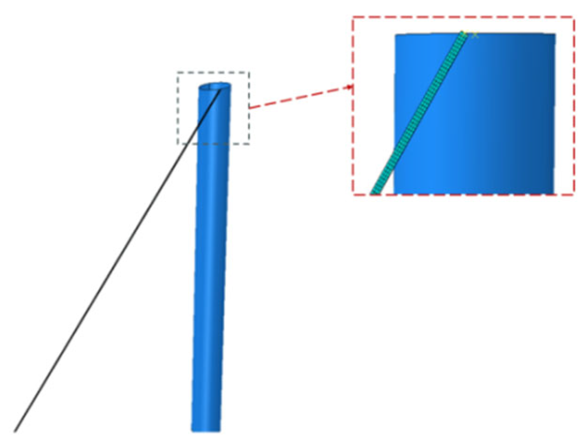
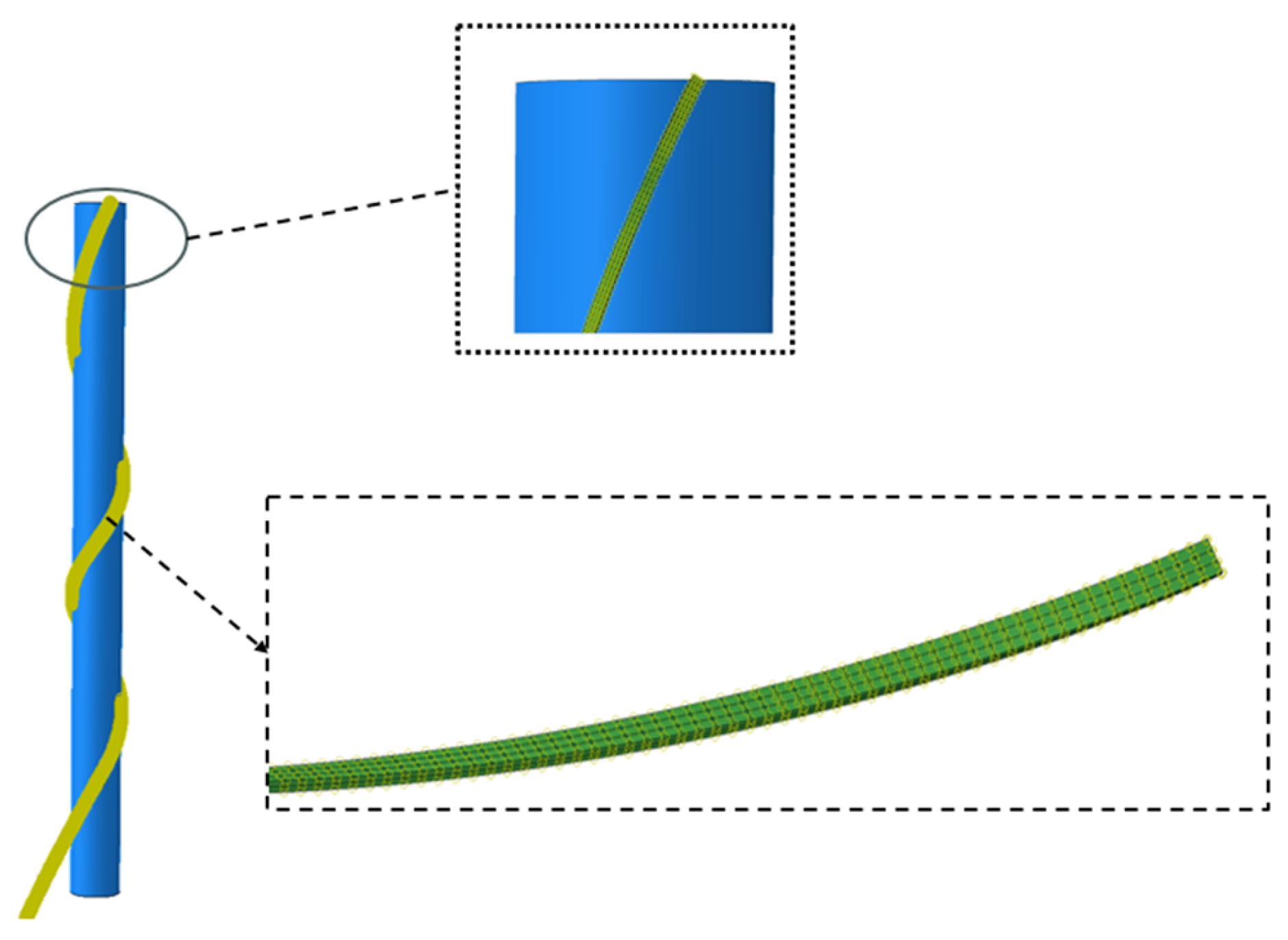
A solid model is usually used to simulate the steel wire, and its cross-section is divided into six elements, as shown in Figure 4 below. The deformation of the wire merging die and the steel wire reel is negligible, so an analytical rigid body approach is used to establish the model. The steel wire winding process usually involves large deformations and nonlinear behaviours. To ensure the accuracy of calculations, a dynamic implicit analysis step is selected in this study. A reference point (RP) is set at the contact end of the steel wire and the flexible riser. Meanwhile, a reference point (RP-1) is set on the central axis at one end of the cylinder. The steel wire and the cylinder are constrained by motion coupling through the reference points. According to the relativity of motion, the cylinder can be rotated instead of the steel wire reel to simulate the 30° winding process. To ensure the stability of the steel wire winding process, the cylinder is constrained to have zero degrees of freedom except for translation and rotation in the Y-direction. The wire merging die is fixed, and a second reference point (RP-1) is set at the other end of the steel wire. A local coordinate system (Datum csys-1) is established along the direction of the steel wire, and the winding tension load is applied along the axial direction of the steel wire. The simulation model of a single steel wire winding is shown in Figure 5 below.

2.2. Analysis of Residual Stress in Steel Wire Cross-Section After Winding

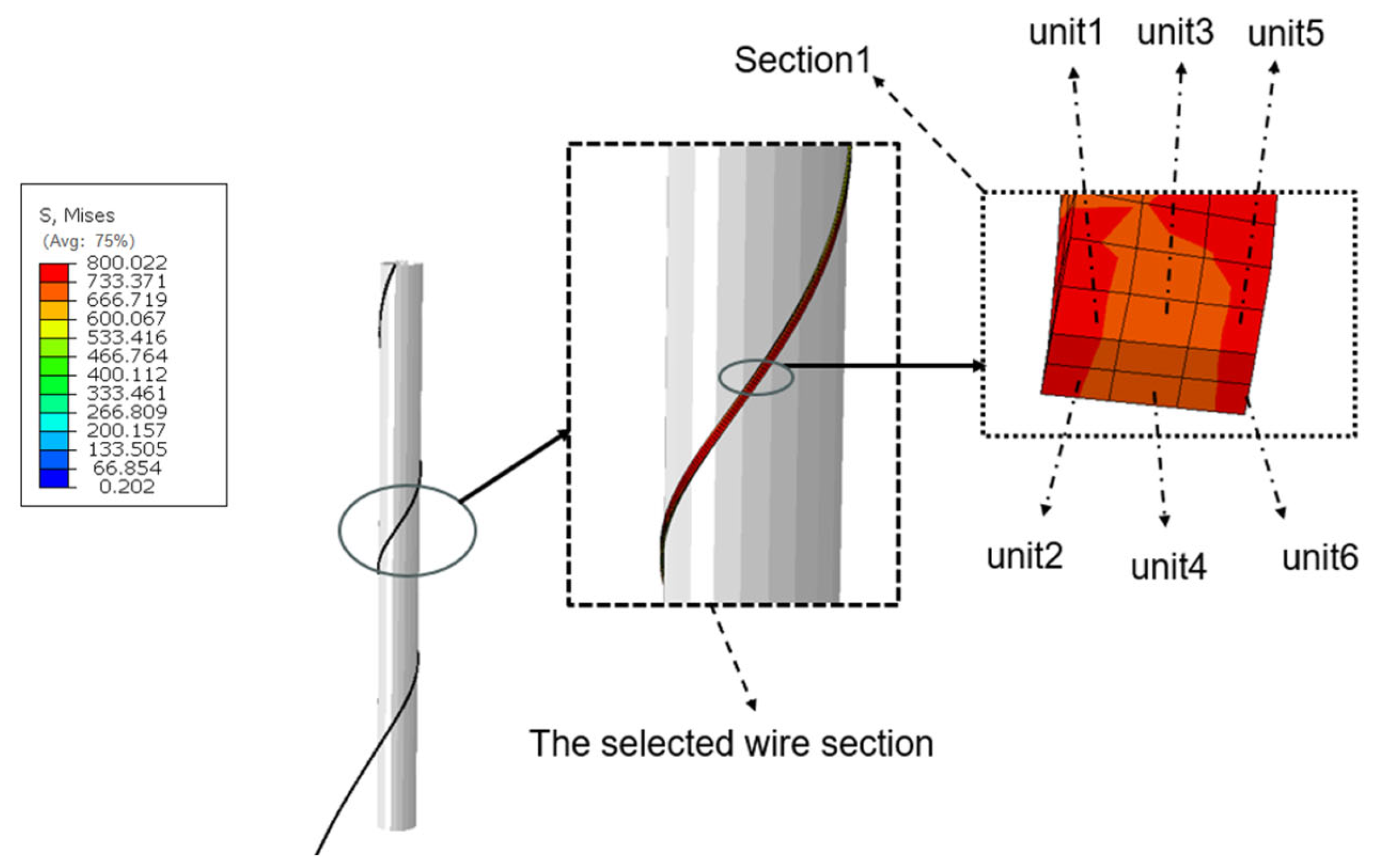
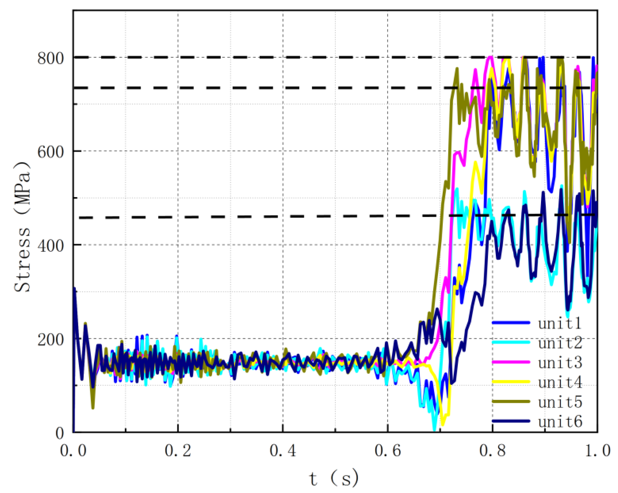
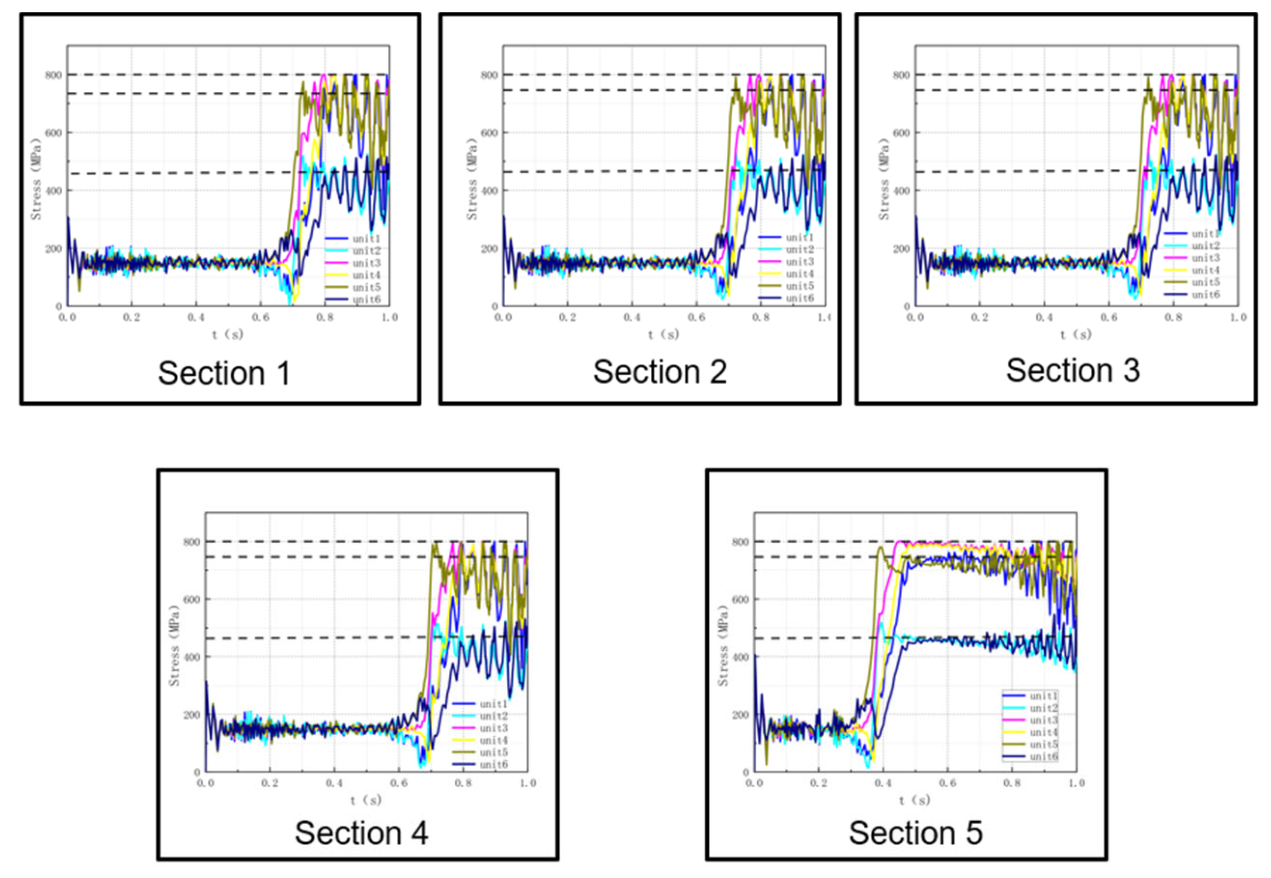
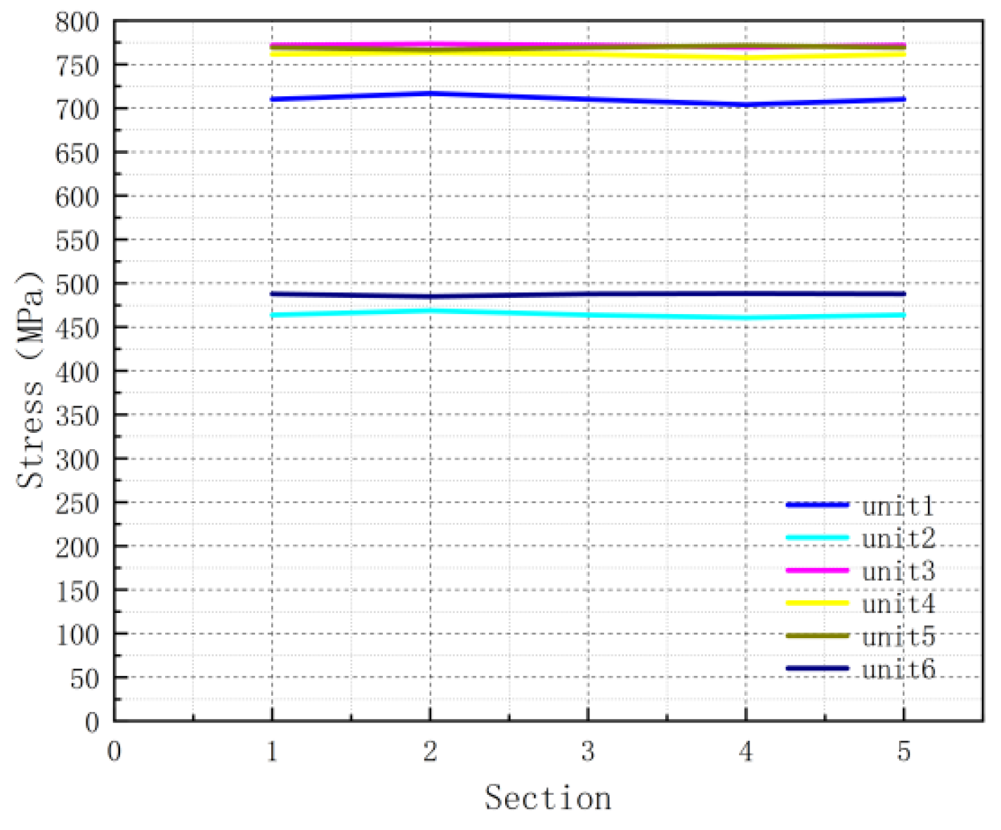
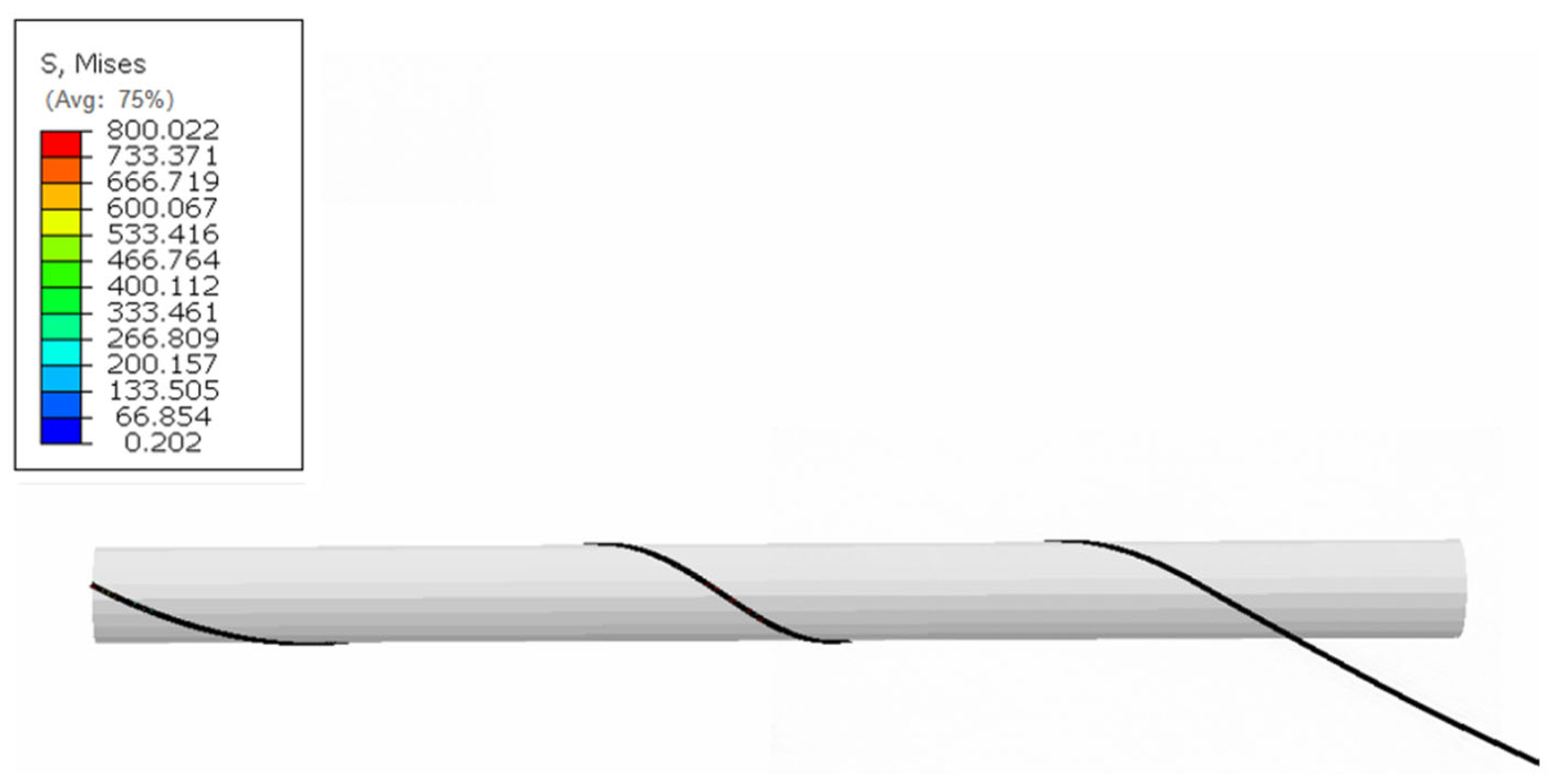
To accurately study the distribution characteristics and uniformity of residual stress along the length of the steel wire after the winding process, the middle section of the steel wire—far from the end constraint effect—was selected as the representative analysis area, as shown in Figure 6. This area is intended to avoid the atypical stress state near the starting and ending ends of winding, which is caused by boundary constraints, sudden changes in contact status, and end effects. Thus, it ensures that the analyzed residual stress field mainly reflects the core influence of the winding process. The simulation calculation adopts a field variable output request, focusing on recording the total stress and plastic strain to comprehensively evaluate the model response and obtain key mechanical information. The stress–strain diagram of the calculation results of the steel wire winding model is shown in Figure 6 below. Five representative cross-sections were selected at equal intervals along the length of the middle section for analysis, and the positions of the selected cross-sections are shown in Figure 7 below. Among them, the stress-time curve of Cross-section 1 is shown in Figure 8; the stress distribution diagram is shown in Figure 9; the stress-time results of all five cross-sections are shown in Figure 10; and the stress comparison diagram of the five cross-sections of the steel wire after winding is shown in Figure 11.
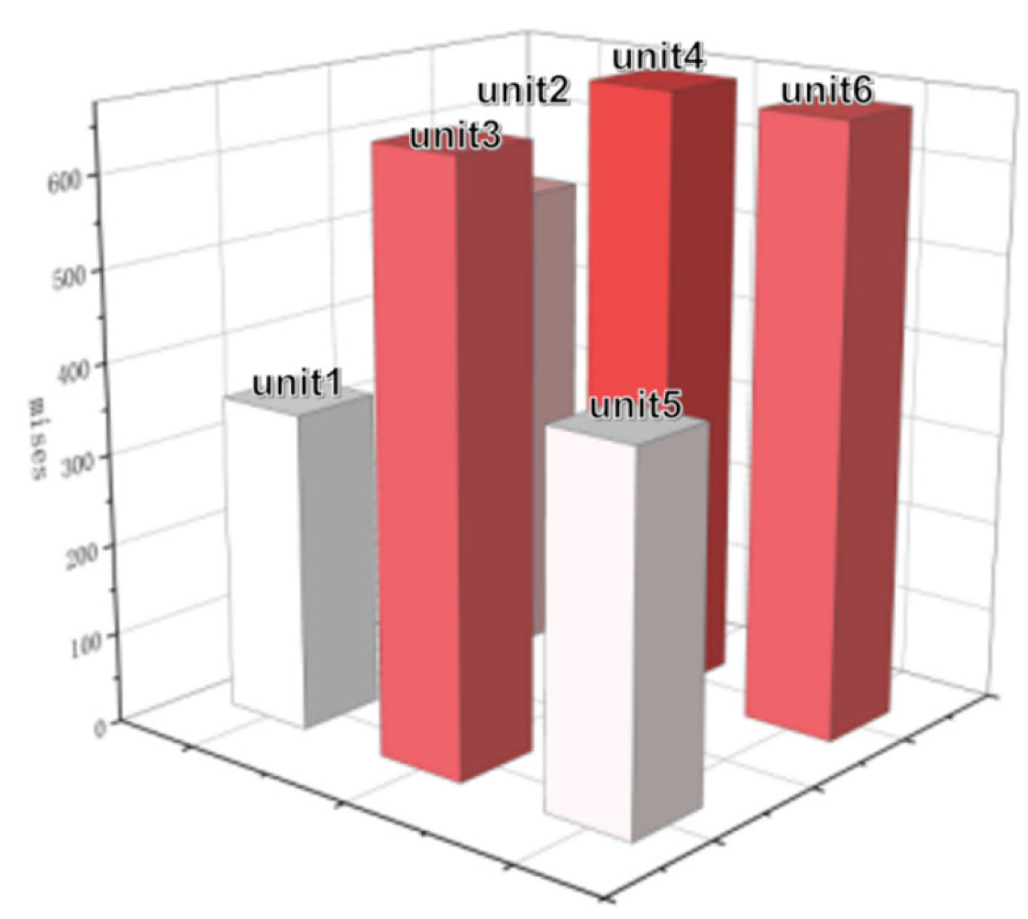
From Figure 9 above, it can be concluded that the residual stress distribution across the cross-section exhibits obvious spatial inhomogeneity. Among the six elements of the cross-section, the maximum residual stress is concentrated in the inner element with the largest bending curvature and the two adjacent middle elements. Their mises stress values are significantly higher than those in other regions, reaching the yield strength, which indicates that these regions have entered the plastic yielding stage during the winding process, while the other three elements show no plastic strain and remain in the elastic deformation state. This phenomenon confirms that the peak residual stress highly coincides with the plastic deformation zone, and the plastic deformation during the bending process is the direct cause of high residual stress. Moreover, the inner element with the largest bending curvature first undergoes plastic deformation due to bearing the maximum tensile strain, and irreversible residual tensile stress is generated after unloading. The adjacent middle elements also reach the yield state and contribute to high residual stress under the combined effect of stress transfer from the plastic zone and their own bending. In contrast, the outer elements remain in the elastic state due to small bending strains, resulting in low residual stress levels. This distribution law confirms the bending-dominated mechanism of the winding process—the peak residual stress and plastic strain zone strictly correspond to the region with the largest geometric curvature.
From Figure 10 and Figure 11, it can be observed that, although there is a stress gradient within the cross-section, there is a high degree of consistency along the axial direction of the steel wire. The mises stress fields of the five cross-sections are basically consistent in axial distribution, and there is no significant difference in the stress values of the elements at the corresponding positions. The residual stress values along the axial path are continuous and stable without local fluctuations. This indicates that, after avoiding the end effect, the winding process forms a stable and reproducible residual stress field in the middle section of the steel wire.
To verify the accuracy of the numerical model for winding processing, the residual stress results from numerical simulation are compared with the theoretical formulas in Reference [29]. Reference [29] provides the relationship between the winding tension and the internal force of the steel wire cross-section after winding:
F A = 1 cos 2 α + sin 2 α cos 2 θ F
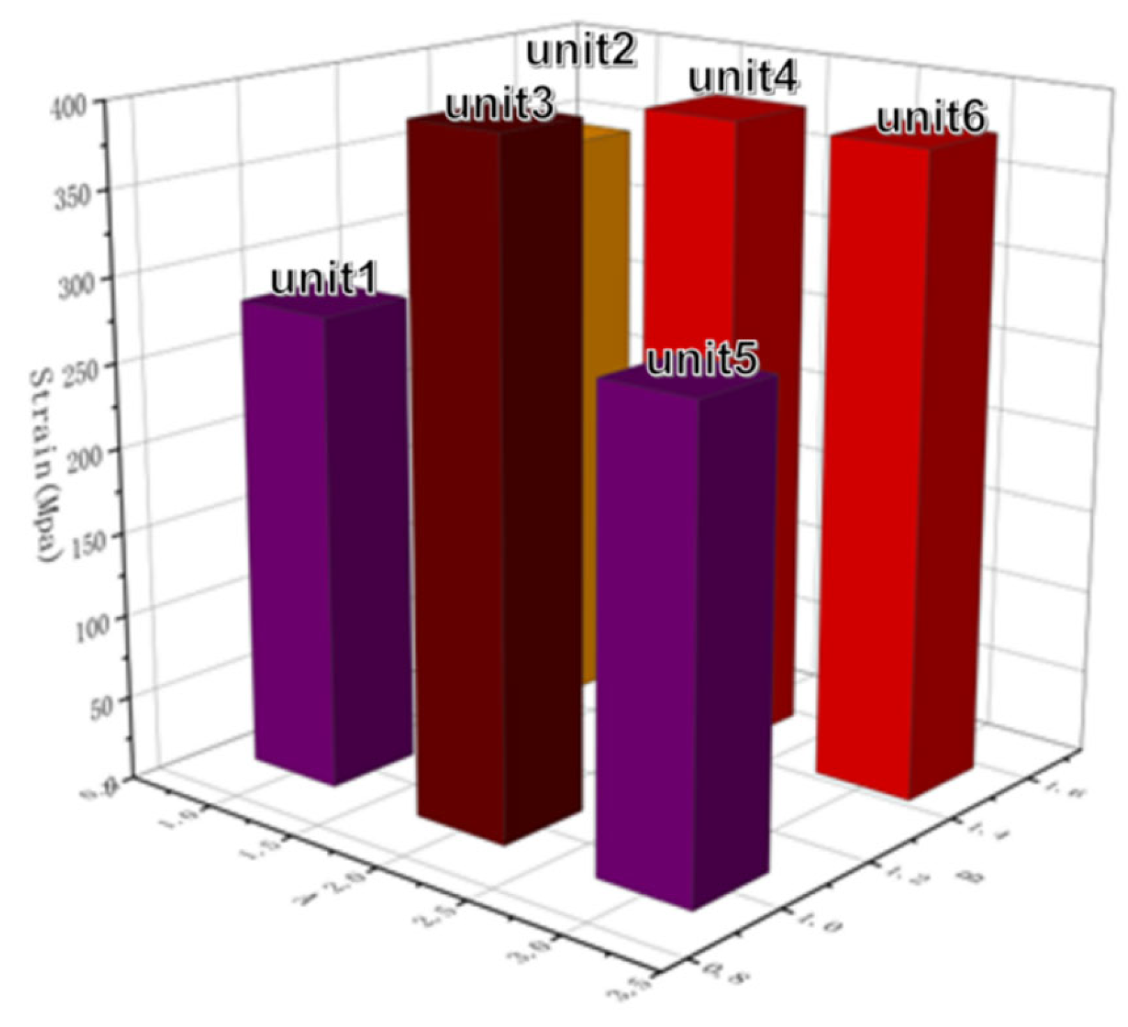
The winding tension in the numerical model is F = 1780 N. The internal force of the armour wire cross-section can be calculated using this theoretical method: F A = 1735   N . The output of the simulation model is shown in Figure 12. Numerical model calculation: Total cross-sectional area of steel strand: S_total = 12 mm × 4 mm = 48 mm2. The cross-section is divided into six units, each with an area of S = 48/6 = 8 mm2. Axial stresses in the six units are 200 MPa, 210 MPa, −220 MPa, 15 MPa, 12 MPa, and 3 MPa. Total axial force calculation: F = 8 × (200 + 210 − 220 + 15 + 12 +3) = 1760 N. The result closely matches the theoretical value, demonstrating the accuracy of the finite element simulation model and the rationality of the winding process analysis.

3. Tensile Loading–Unloading Model of Armour Wires with Processing-Induced Residual Stress

3.1. Model Establishment

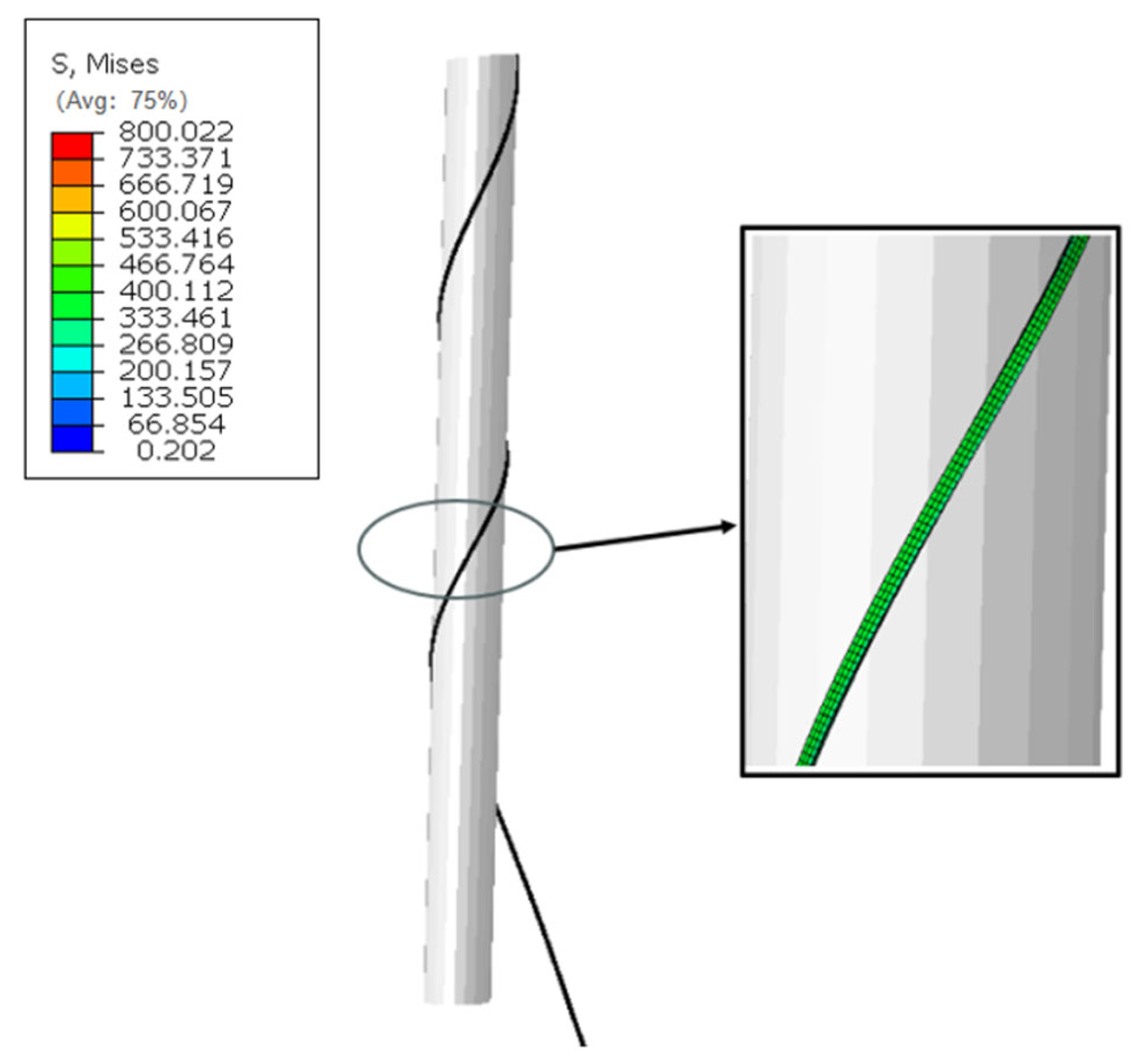
In the simulation of the cyclic tensile behaviour of steel wires after the winding process, to accurately reflect the actual state of the steel wires before service, the final state obtained from the numerical simulation of the winding process was used as the initial condition and imported into the cyclic tension model in this study. Using the predefined field function of ABAQUS, the result file at the end of the winding simulation was mapped to the steel wire component of the cyclic tension model. This process accurately imported the residual stress field distribution across the steel wire cross-section after winding, the geometric deformation state caused by winding, and the key material hardening history. Mesh sensitivity and convergence analyses were conducted to ensure that the mapped residual stress field retained its spatial distribution and magnitude without significant numerical diffusion. The model after the successful import of the residual stress field is shown in Figure 13, and the stress distribution diagram after import is shown in Figure 14. This import method maximizes the physical authenticity of the starting point of the cyclic tension simulation, avoiding significant errors caused by starting calculations from a state of no residual stress, no geometric deformation, and no hardening. It is crucial for accurately studying the mechanical response of the steel wire under cyclic tensile loads. For the load application mechanism, displacement loading was used to directly control the boundary motion, avoiding the risk of “infinite deformation” in force loading. The loading history was precisely defined through a piecewise linear amplitude curve to simulate the actual tension-unloading process. The mandrel and the tail end of the steel wire winding were set with fully fixed constraints. The tail end of the wire is coupled to a reference point (RP) on the mandrel with a constraint, and a fixed constraint is applied (all degrees of freedom are restricted). At the starting end (loading end) of the steel wire winding, it was coupled with another reference point (RP-1) on the mandrel for motion. The axial cyclic tensile displacement load was directly applied to RP-1. To simulate the dominant axial tension behaviour, only the translational degree of freedom along the axial direction of the steel wire was retained in the model, while the other degrees of freedom were constrained to prevent unintended rigid body motion or bending. The element type selected for the steel wire was C3D8R, mainly because the C3D8R element achieves a good balance between calculation accuracy and efficiency, making it suitable for large-model calculations. The reduced integration technology makes it insensitive to shear locking when simulating bending and contact problems, which is crucial for problems involving bending deformation and complex contact during the winding process and can provide more accurate stress results, as well as effectively handle material nonlinearity. This element type is generally compatible with the residual stress field and deformation state imported from the winding stage. In terms of the contact algorithm, a dynamic implicit analysis step was adopted. The contact behaviour between the steel wire and the mandrel is usually highly nonlinear. The implicit dynamic analysis is generally more robust than static analysis in handling the convergence of such complex, state-changing contacts. During the cyclic loading process, especially during yielding, reverse yielding, or sudden changes in contact status, local convergence difficulties may occur. The implicit dynamic analysis step helps overcome these local instabilities by introducing inertial effects, improving the robustness of the overall solution. The cyclic tensile analysis employed an elastic-perfectly plastic material model to determine the shakedown limit load based on the initial yield criterion.

3.2. Discussion on the Residual Stress Distribution in Steel Wire Cross-Section After Loading and Unloading

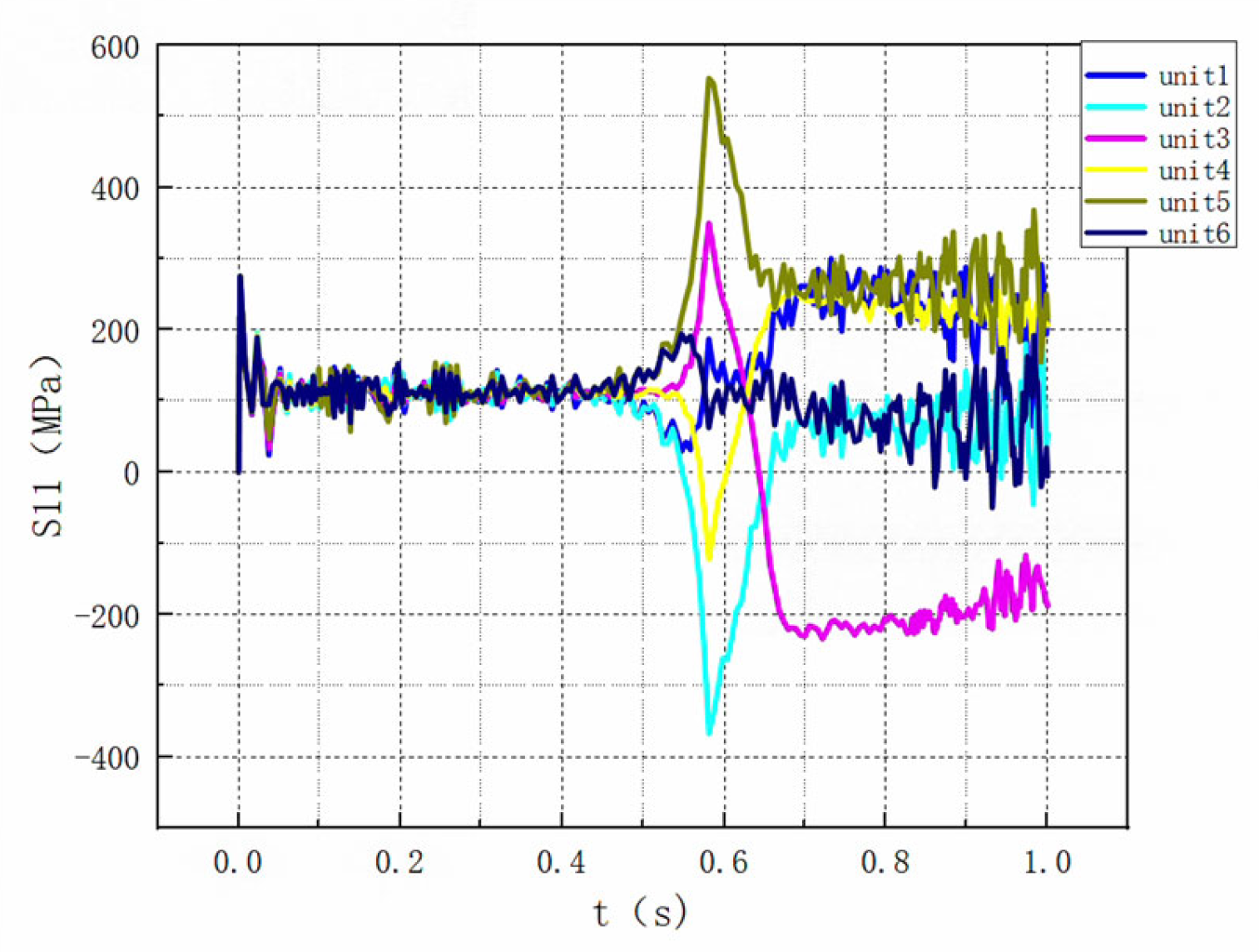
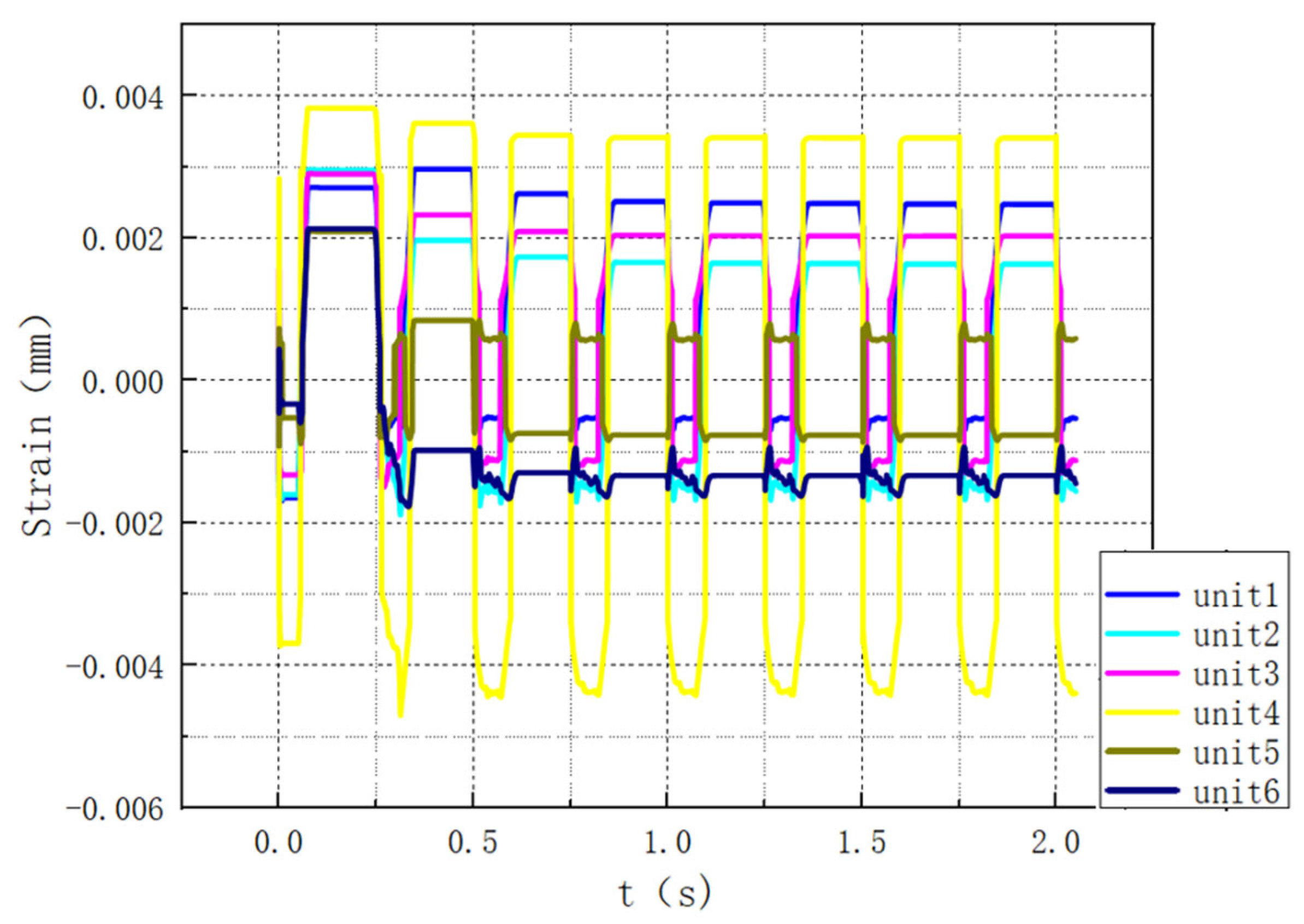
To systematically study the evolution behaviour of residual stress in the wound steel wire under service loads, based on the initial residual stress field, this study imported the stress field as the initial condition and applied cyclic tension-unloading loads to the steel wire. The stress distribution diagram of Cross-section 1 is shown in Figure 15; the simulation calculation continued the field variable output request, and a displacement of 0–16.1 kN was applied. The stress–strain diagrams of Cross-section 1 of the steel wire under different unloading times are shown in Figure 16 below; the strain-time curves of Cross-section 1 with and without residual strain output from the model are shown in Figure 17 and Figure 18 below.
As shown in Figure 18, the structure exhibits complete stress recovery upon unloading in the absence of residual stress, confirming its ideal elastic shakedown behaviour. In contrast, Figure 17 demonstrates that residual stress fundamentally undermines this self-restoring capacity, leaving the structure with persistent non-zero strain and locking it into a preloaded state. These findings confirm that residual stress not only compromises structural stability but also elevates the risk of progressive failure under cyclic loading.

4. Study on Cyclic Tension Shakedown Behaviour

The stress–strain diagram of the calculation results of the cyclic tension model of steel wires with residual stress is shown in Figure 19 below, which is consistent with the model without residual stress and is divided into three parts. To improve the accuracy of the output curve, a field variable output request was adopted in this model calculation, and the output variables included stress and strain. The comprehensive recording of these output variables facilitates the comprehensive evaluation of the model, thereby enabling a more comprehensive and accurate analysis of the system response. The transition between shakedown and ratcheting was identified based on the convergence or divergence of plastic strain accumulation over successive cycles. Shakedown criterion: Stability refers to the condition where a structure, after undergoing a finite number of cyclic loading cycles, no longer accumulates plastic deformation but only exhibits elastic deformation. Melan’s static stability criterion: A structure is considered stable if there exists a time-independent static stress field such that the deviation between the actual stress at every point in the structure and this static stress field remains within the material’s elastic limit. Ratcheting judgement criterion refers to the ‘cyclic accumulation characteristic of plastic strain’ in structures under asymmetric cyclic loading. The strain accumulation criterion states the following: If plastic strain increases monotonically with each cycle (without a convergence tendency), the structure exhibits a ratchet effect. The shakedown state was quantified by the decay of the plastic strain increment per cycle to below 1 × 10⁻⁵, while ratcheting was characterized by a persistent strain increment exceeding this threshold.
When a displacement of 0–16.1 kN was applied, Cross-section 1 of the steel wire was selected, and the plastic strain of the steel wire was obtained, as shown in Figure 20 below.
As shown in Figure 20, the structure attains an ideal cyclic shakedown state, with its maximum deformation capacity being consistently maintained under the prescribed loading conditions. This behaviour reflects a fully stabilized structural response. The uniform peak strain observed in each cycle serves as a clear indicator of cyclic stability, demonstrating that the structure has developed a repeatable hysteresis loop after initial conditioning. These results confirm the structure’s ability to sustain cyclic loading without progressive strain accumulation or stiffness degradation.
When a displacement of 0–30.2 kN was applied, Cross-section 1 of the steel wire was selected, and the plastic strain diagram of a wire unit is shown in Figure 21 below.
Based on the numerical simulation results shown in Figure 21, the strain accumulation exhibits a characteristic stair-step growth pattern with each loading cycle, demonstrating typical ratcheting behaviour. After several loading–unloading cycles, the cumulative strain reaches the maximum allowable strain limit of the material, eventually leading to the tensile fracture failure of the armour wire.
It is worth noting that, in the tensile resistance design of flexible risers, the design is usually based on the ultimate tensile breaking force, and the estimation method of the ultimate tensile breaking force is shown in the following:
F = σ A cos α
The ultimate tensile breaking fore of one armour wire can be calculated from Table 1, which is 33.3 kN. Through Figure 21, we discovered that repeated tensile forces induce a ratchet effect in riser armour plates. In this case, the critical load for the ratchet effect is 30.1 kN, which is lower than the ultimate tensile strength. Since flexible risers are subjected to repeated tensile loads during processing, installation, and operational conditions, it is essential to apply the proposed method in this study to analyze the stability of riser pipes under cyclic tensile loads in practical engineering applications.
The currently established numerical model does not account for the effects of temperature, corrosion, and varying friction coefficients on shakedown behaviour. Moving forward, research that incorporates these factors and conducts relevant experiments would be of great value for advancing this investigation further.

5. Conclusions

In this study, a numerical simulation model for the winding process of armour wires in flexible risers was established, and the stress distribution in the cross-section of the armour wires after processing was quantified. Furthermore, residual stress was incorporated into the analysis, and a simulation methodology for investigating the shakedown behaviour of flexible risers during the cyclic tensile load was developed. The key findings are as follows:
The residual stress of armour wires after the winding process exhibits inhomogeneity in the cross-section, with the maximum residual stress concentrated in the inner elements. During the initial loading–unloading process of the example pipe, the stress in the armour wire cross-section undergoes obvious redistribution.
When cyclic loading is applied with a tensile force of 0–16.1 kN, the armour wire cross-section tends to reach a shakedown state as the number of loading cycles increases.
When cyclic loading is applied with a tensile force of 0–30.1 kN, the strain of the armour wire cross-section gradually increases with each loading–unloading cycle, exhibiting a ratcheting effect.
When a flexible riser is subjected to cyclic tensile loads, the riser may fail due to the ratcheting effect occurring inside the armour wires, even if the tensile load is less than the ultimate tensile breaking force of the pipe. Therefore, in the design of flexible risers, the shakedown behaviour of the riser under cyclic tensile loads should be considered.

Author Contributions

Conceptualization, S.W.; Software, S.W.; Validation, E.S.; Formal analysis, X.Y.; Investigation, J.L.; Writing—original draft, X.Y.; Writing—review & editing, Z.S. All authors have read and agreed to the published version of the manuscript.

Funding

This research was funded by National Natural Science Foundation of China grant number (52201395).

Data Availability Statement

Should you need to access the data for research verification or related purposes, please feel free to contact the corresponding author directly.

Conflicts of Interest

Author Ersu Shang was employed by the company VH-Marinetech Co., Ltd. The remaining authors declare that the research was conducted in the absence of any commercial or financial relationships that could be construed as a potential conflict of interest.

References

  1. Knapp, R. Nonlinear analysis of a helically armoured cable with nonuniform mechanical properties in tension and torsion. In Proceedings of the Ocean 75 Conference, San Diego, CA, USA, 22–25 September 1975; IEEE: New York, NY, USA, 1975; pp. 155–164. [Google Scholar]
  2. Knapp, R.H. Derivation of a new stiffness matrix for helically armoured cables considering tension and torsion. Int. J. Numer. Methods Eng. 1979, 14, 515–529. [Google Scholar] [CrossRef]
  3. Knapp, R.H. Torque and stress balanced design of helically armoured cables. J. Eng. Ind. 1981, 103, 61–66. [Google Scholar] [CrossRef]
  4. Lanteigne, J. Theoretical estimation of the response of helically armoured cables to tension, torsion, and bending. J. Appl. Mech. 1985, 52, 423–432. [Google Scholar] [CrossRef]
  5. LeClair, R.A.; Costello, G.A. Axial, bending and torsional loading of a strand with friction. J. Offshore Mech. Arct. Eng. 1988, 110, 38–42. [Google Scholar] [CrossRef]
  6. Jolicoeur, C.; Cardou, A. A numerical comparison of current mathematical models of twisted wire cables under axisymmetric loads. J. Energy Resour. Technol. 1991, 113, 241–249. [Google Scholar] [CrossRef]
  7. Witz, J.A.; Tan, Z. On the axial-torsional structural behaviour of flexible pipes, umbilicals and marine cables. Mar. Struct. 1992, 5, 205–227. [Google Scholar] [CrossRef]
  8. Custódio, A.; Vaz, M. A nonlinear formulation for the axisymmetric response of umbilical cables and flexible pipes. Appl. Ocean. Res. 2002, 24, 21–29. [Google Scholar] [CrossRef]
  9. Ramos, R., Jr.; Pesce, C.P. A consistent analytical model to predict the structural behavior of flexible risers subjected to combined loads. J. Offshore Mech. Arct. Eng. 2004, 126, 141–146. [Google Scholar] [CrossRef]
  10. Yue, Q.; Lu, Q.; Yan, J.; Zheng, J.; Palmer, A. Tension behavior prediction of flexible pipelines in shallow water. Ocean. Eng. 2013, 58, 201–207. [Google Scholar] [CrossRef]
  11. Xiang, L.; Wang, H.; Chen, Y.; Guan, Y.; Wang, Y.; Dai, L. Modeling of multi-strand wire ropes subjected to axial tension and torsion loads. Int. J. Solids Struct. 2015, 58, 233–246. [Google Scholar] [CrossRef]
  12. Foti, F.; di Roseto, A.D.L. Analytical and finite element modelling of the elastic–plastic behaviour of metallic strands under axial–torsional loads. Int. J. Mech. Sci. 2016, 115, 202–214. [Google Scholar] [CrossRef]
  13. Blkich, H. Über die Bemessung statisch unbestimmter Stahlwerke unter Berücksichtigung des elastischplastischen Berhaltens des Baustoffes. Bauingenieur 1932, 13, 261–267. [Google Scholar]
  14. Melan, E. Theorie Statisch Unbestimmter Systeme aus Ideal-Plastischem Baustoff; Hölder-Pichler-Tempsky in Komm: Prambachkirchen, Austria, 1936. [Google Scholar]
  15. Melan, E. Zur plastizität des räumlichen kontinuums. Ing.-Arch. 1938, 9, 116–126. [Google Scholar] [CrossRef]
  16. Koiter, W.T. A new general theorem on shakedown of elastic-plastic structures. Proc. Koninkl. Ned. Akad. Wet. B 1956, 59, 24–34. [Google Scholar]
  17. Ponter, A.R.S.; Karadeniz, S. An extended shakedown theory for structures that suffer cyclic thermal loading, Part 1: Theory. J. Appl. Mech. 1985, 52, 877–882. [Google Scholar] [CrossRef]
  18. Polizzotto, C. On the conditions to prevent plastic shakedown of structures: Part I—Theory. J. Appl. Mech. 1993, 60, 15–19. [Google Scholar] [CrossRef]
  19. Prager, W. A new method of analyzing stresses and strains in work-hardening plastic solids. J. Appl. Mech. 1956, 23, 493–496. [Google Scholar] [CrossRef]
  20. Besseling, J.F. A theory of elastic, plastic, and creep deformations of an initially isotropic material showing anisotropic strain-hardening, creep recovery, and secondary creep. J. Appl. Mech. 1958, 25, 529–536. [Google Scholar] [CrossRef]
  21. Armstrong, P.J.; Frederick, C.O. A Mathematical Representation of the Multiaxial Bauschinger Effect; Nuclear Laboratories: Berkeley, CA, USA, 1966; Volume 731. [Google Scholar]
  22. Chaboche, J.L. Time-independent constitutive theories for cyclic plasticity. Int. J. Plast. 1986, 2, 149–188. [Google Scholar] [CrossRef]
  23. Chaboche, J.L. On some modifications of kinematic hardening to improve the description of ratchetting effects. Int. J. Plast. 1991, 7, 661–678. [Google Scholar] [CrossRef]
  24. Han, K.; Chen, Z.-F.; Wang, W.; Shi, L.; Lu, K.-Q. A short review of ratcheting effect in pressurized piping. Int. J. Press. Vessel. Pip. 2023, 205, 105009. [Google Scholar] [CrossRef]
  25. Fernando, U.S.; Davidson, M.; Simpson, C.; Pirling, T.; Yan, K.; Callaghan, M.D.; Roy, M.; Francis, J.A.; Withers, P.J. Measurement of residual stress shakedown in pressure/tensile armour wires of flexible pipes by neutron diffraction. In Proceedings of the ASME 2015 34th International Conference on Ocean, Offshore and Arctic Engineering, St. John’s, NL, Canada, 31 May–5 June 2015; American Society of Mechanical Engineers: New York, NY, USA, 2015. [Google Scholar]
  26. Sævik, S.; Gray, L.; Phan, A. A method for calculating residual and transverse stress effects in flexible pipe pressure spirals. In Proceedings of the 20th International Conference on Offshore Mechanics and Arctic Engineering (OMAE 2001 CD), Rio de Janeiro, Brazil, 3–8 June 2001; pp. 3–8. [Google Scholar]
  27. Fernando, U.S.; Tan, Z.; Sheldrake, T.; Clements, R. The stress analysis and residual stress evaluation of pressure armour layers in flexible pipes using 3D finite element models. In Proceedings of the International Conference on Offshore Mechanics and Arctic Engineering, Vancouver, BC, Canada, 20–25 June 2004; Volume 37459, pp. 57–65. [Google Scholar]
  28. Tang, M.; Yan, J.; Chen, J.; Yang, Z.; Yue, Q. Residual Stress Evaluation and Buckling Analysis of Carcass Layers in Flexible Pipes Using 3D Finite Element Model. In Proceedings of the ASME 2015 34th International Conference on Ocean, Offshore and Arctic Engineering, St. John’s, NL, Canada, 31 May–5 June 2015; American Society of Mechanical Engineers: New York, NY, USA, 2015. [Google Scholar]
  29. Lu, Q.; Wu, S.; Wang, D.; Yang, Z.; Yin, Y.; Hu, H.; Yan, J.; Yue, Q. Study on mechanical behavior of tensile armour wires of marine flexible pipes and cables during winding process. In Proceedings of the International Conference on Offshore Mechanics and Arctic Engineering, Glasgow, UK, 9–14 June 2019; American Society of Mechanical Engineers: New York, NY, USA, 2019; Volume 58806. [Google Scholar]
  30. Pan, Y.; Zheng, L.; Yang, S.; Wang, Y. A review of fatigue analysis of marine flexible risers. Geoenergy Sci. Eng. 2024, 246, 213555. [Google Scholar] [CrossRef]
  31. Bao, R.; Liu, J.; Xiao, Z. Stress and failure analysis of composite flexible riser subjected to torsion and thermomechanical loading. In Proceedings of the International Ocean and Polar Engineering Conference, Rhodes, Greece, 16–21 June 2024; ISOPE: Mountain View, CA, USA, 2024. [Google Scholar]
Figure 1. Schematic diagram of typical flexible riser structure.
Jmse 13 02186 g001
Figure 2. Tensile failure of deepwater flexible riser.
Jmse 13 02186 g002
Figure 3. Winding process for armour wires of flexible risers.
Jmse 13 02186 g003
Figure 4. Mesh generation of armour wire cross-section.
Jmse 13 02186 g004
Figure 5. Numerical model for winding process of armour wire.
Jmse 13 02186 g005
Figure 6. Residual stress distribution of armour wire cross-section after winding.
Jmse 13 02186 g006
Figure 7. Stress contour of armour wire after winding.
Jmse 13 02186 g007
Figure 8. Variation in mises stress with time in the armour wire winding process.
Jmse 13 02186 g008
Figure 9. Mises stress distribution of armour wire cross-section after winding.
Jmse 13 02186 g009
Figure 10. Variation in mises stress with time in the different cross-sections of the armour wire after winding.
Jmse 13 02186 g010
Figure 11. Comparison of mises stress of different cross-sections of armour wire after winding.
Jmse 13 02186 g011
Figure 12. Axial stress of six elements in the armour wire section.
Jmse 13 02186 g012
Figure 13. Numerical model for cyclic tensile loading of armour wire.
Jmse 13 02186 g013
Figure 14. Stress contour of armour wire after residual stress import.
Jmse 13 02186 g014
Figure 15. Mises stress distribution of cross-section after tensile loading and unloading.
Jmse 13 02186 g015
Figure 16. Stress–strain diagram of cross-section of armour wire.
Jmse 13 02186 g016
Figure 17. Variation in strain with time in cross-section with residual stress during loading–unloading process.
Jmse 13 02186 g017
Figure 18. Variation in strain with time in cross-section without residual stress during loading–unloading process.
Jmse 13 02186 g018
Figure 19. Mises stress diagram of numerical model.
Jmse 13 02186 g019
Figure 20. Plastic strain of armour wire cross-section during 0–16.1 kN loading–unloading process.
Jmse 13 02186 g020
Figure 21. Plastic strain of armour wire cross-section during 0–30.2 kN loading–unloading process.
Jmse 13 02186 g021
Table 1. Armour wire structural parameters.
WidthThicknessWinding RadiusWinding AngleElastic ModulusYield StrengthWire Merging Die Radius
12 mm4 mm127 mm30°2 × 10⁵ MPa800 Mpa132 mm
Disclaimer/Publisher’s Note: The statements, opinions and data contained in all publications are solely those of the individual author(s) and contributor(s) and not of MDPI and/or the editor(s). MDPI and/or the editor(s) disclaim responsibility for any injury to people or property resulting from any ideas, methods, instructions or products referred to in the content.