1. Introduction
With the advancement of global high-tech industries and the transition in energy systems, the demand for critical metals such as nickel, cobalt and manganese has increasingly outpaced supply. Deep-sea area, which contains abundant critical metals including nickel, cobalt, copper and manganese, has consequently emerged as a new frontier for the development of rare metal supplies [
1,
2,
3,
4,
5]. Over recent decades, four primary deep-sea mining systems have been engineered [
6], namely the drag-head bucket system [
7], the continuous line bucket system [
8], the shuttle vessel system [
9], and the pipe lift system [
10]. Within the existing technological system for deep-sea mining, the pipe lift system is recognized as the most commercially promising approach due to its high operational efficiency [
11]. The lifting pipe, which connects the subsea buffer station and the surface mining vessel, serves as one of the core components for mineral transport. Flexible pipes, known for their excellent fatigue resistance, low weight-to-empty ratio, and ease of installation, are considered a preferred option for pipe lift systems. However, the complex structural configuration of flexible pipes presents significant challenges in both design and manufacturing [
12].
Flexible pipes are typically composed of multiple composite layers, including an inner liner, pressure reinforcement layers, tensile reinforcement layers, and an outer protective layer [
13]. The inner liner, which serves as the innermost layer of the flexible pipe, is in direct contact with the transported slurry mixture and subjected to long-term abrasion from mineral particles [
14]. As the primary barrier for material transport, the integrity and reliability of the inner liner are critical. To achieve superior wear resistance, polymers such as ultra-high molecular weight polyethylene (UHMWPE) are commonly used for the inner liner. The inner liner is manufactured through an extrusion process, which involves stages such as feeding, melting, extrusion, sizing, cooling, haul-off, and coiling [
14]. In the polymer extrusion process, both the cross-section of the die flow channel and the temperature vary. Variations in the characteristic dimensions of the flow channel affect wall slip, convective heat transfer, and viscous dissipation. The viscosity of the polymer melt changes with shear rate and temperature. Establishing a theoretical model that reflects the flow characteristics of the melt during extrusion is a prerequisite for simulating the extrusion process of liners. Some researchers have proposed various constitutive equations that can characterize the rheological properties of polymer melts [
15,
16]. The power-law model, the most widely used constitutive equation, relates melt viscosity and consistency to shear rate through an index that characterizes the non-Newtonian behavior of the melt [
17]. However, the power-law model has a limited range of applicability. To describe the rheological properties of melts over a wider range of shear rates, Carreau [
18] proposed a new constitutive model based on the influence of different characteristic parameters, which can be transformed into the Bird–Carreau model or the Carreau–Yasuda model under certain conditions. For non-isothermal flow simulations of the liner flow process, the Carreau–Yasuda law is typically employed to characterize the relationship between polymer viscosity and shear rate. Davis [
19] used the Arrhenius shear stress constitutive equation to describe the effects of shear rate and temperature on polymer viscosity. For fluids with highly temperature-sensitive viscosity, the shear rate–shear stress curve is S-shaped, and the Arrhenius shear stress constitutive equation performs better.
In the extrusion molding of flexible pipe liners, the design of die determines melt distribution and shaping quality, making it a critical step in ensuring dimensional stability and surface quality of the product. For thin-walled components such as flexible pipe liners, the flow channel must achieve balanced flow distribution, ensuring that the mass flow rate of each branch matches its effective cross-section and that a consistent die-swelling velocity is obtained at the die exit, thereby ensuring a stable and controllable molding process [
20,
21,
22,
23,
24,
25]. Koziey [
26] proposed a classic design principle, which remains an important basis for flow channel layout and flow distribution optimization. During the design, the flow channel cross-section is divided into zones, and the geometric shape and dimensions are adjusted to ensure that the mass flow rate of each zone matches its area ratio. Focusing on the goal of achieving a consistent die-swelling velocity, Zhang et al. [
27] combined transition-line theory with a variable flow channel size method to derive the cavity profiles of each module and programmatically verified flow balance. Simulation results showed a high degree of consistency with empirical values, demonstrating the feasibility and efficiency of a computation-driven approach compared to traditional trial-and-error parameter selection. With advances in computational fluid dynamics (CFD) and optimization algorithms, numerical analysis is becoming a mainstream method for optimizing mold structural parameters and accelerating design convergence. A numerical platform for coupled polymer rheology-thermal analysis was developed by Xing et al. [
28]. Sensitivity analysis was conducted on key parameters, including die diameter and sizing length. Subsequently, the structural sizing was completed based on the analysis and validated experimentally, achieving a stable and balanced flow distribution. Sienz et al. [
29] conducted extensive experimental and simulation comparisons to quantify the impact of sizing length on melt velocity stability. Their work proposed an optimization objective function and constraint system for melt flow, which provides actionable evaluation metrics for sizing length design.
Optimization of die design provides a foundation for the extrusion molding of liners, but achieving high-quality liner extrusion also requires crucial research on the molding process. Studies on the extrusion molding process of liners primarily focus on controlling key process parameters for polymer materials with specific shapes and functional requirements during molding. The heating, shear and cooling stages during extrusion are highly interdependent. Parameters such as temperature, screw speed, pressure, die geometry and sizing conditions collectively govern the spatial distribution of the viscosity and velocity fields, which in turn dictates the wall thickness uniformity, ovality and residual stress of the product. Integrating process mechanism models with numerical simulations clarifies the sensitivity of various parameters to molding quality and allows for the synergistic optimization of traction speed, die gap and cooling intensity. This capability enables the precision extrusion of liners under complex stress states, significantly reducing the probability of dimensional deviations and molding defects [
30,
31,
32,
33]. Some researchers have focused on the extrusion molding process of liners. Davidson and Wang [
34] conducted a process mechanics analysis of profile extrusion using the finite element method, providing characterization methods for the elastic stress concentration factor and overall axial strain of liners. A mathematical model of the extrusion process was established by Walczuk [
35] and validated experimentally on a single-screw extruder using low-density polyethylene (LDPE). Data were obtained for key quantities, including mass flow rate, temperature, pressure and energy consumption. The good agreement between the calculated results and measurements confirmed the validity of the model within the practical engineering range. Pettas et al. [
36] conducted a linear stability analysis to quantify the impact of extrusion speed changes on the flow stability regions and disturbance amplification of viscoelastic fluids in planar dies. The results provided practical criteria for optimizing the process window and suppressing defects in the die zone.
The development of numerical simulation technology and the maturation of polymer extrusion forming theory have provided a theoretical basis and methodological tools for the process mechanics analysis of flexible pipe liner extrusion. However, the complex thermo-mechanical coupling behavior during extrusion, particularly the flow state transition of ultra-high molecular weight polyethylene from solid feeding to melt extrusion and long-distance flow, poses challenges in constructing numerical models that accurately reflect the entire flow process. Most existing numerical simulation models focus only on the flow behavior of extruded materials at the feed port or die-forming section and the optimization of extruder structural parameters. This paper establishes a numerical simulation model for the full flow process of flexible pipe liner extrusion forming based on the Euler–Lagrangian coupling method, conducts research on the evolution patterns of physical fields such as heat flux and stress during UHMWPE extrusion, and focuses on the influence of temperature and screw speed on the mechanical behavior of extrusion, providing theoretical and technical support for optimizing process parameters and quality control in flexible pipe liner extrusion.
The remaining of this paper is organized as follows. In
Section 2, the numerical simulation model for the extrusion process is expounded.
Section 3 focuses on the verification of the numerical simulation model. In
Section 4, the evolution patterns of physical fields during UHMWPE extrusion are provided, and the influence of temperature and screw speed on the mechanical behavior of extrusion are revealed. Finally, the conclusions are summarized in
Section 5.
2. Numerical Simulation Model for the Extrusion Process
2.1. Numerical Simulation Method
The extrusion process of the inner lining layer of flexible pipes can be divided into three basic stages, namely the feeding section, the melting section and the melt conveying section. During extrusion, the material transitions from a solid to a molten state through the coordinated action of the machine barrel’s sections, resulting in a uniform melt output. The numerical simulation analysis was carried out using the Coupled Eulerian–Lagrangian (CEL) method. The CEL method is an approach designed to address issues such as large deformations, material flow and contact interactions. During the calculation process, the mesh remains fixed while the material flows within it. In finite element analysis, particle motion is described in the Eulerian framework. The mesh nodes are fixed in space, and the particles are independent of the mesh points. By transforming the Lagrangian governing equations into Eulerian control equations through the CEL method, solid mechanics problems can be effectively described. This enables the accurate solution of large-deformation problems in solid mechanics. The Lagrangian description is employed to represent the conservation equations of mass, momentum and energy.
ρ represents density,
v represents the velocity of a particle,
σ represents Cauchy stress,
b represents Volumetric force,
e1 represents the internal energy per unit volume,
represents the strain rate, the symbol “
“ represents the double dot product of tensors,
represents the gradient operator, and
represents the divergence of the velocity vector. When the above physical quantities are expressed as a field function
ψ(
x,
t), they can be written in functional form in terms of the spatial coordinates
x and time
t. By applying the chain rule of differentiation, the total derivative of
ψ(
x,
t) with respect to time can be determined.
Substituting Equation (4) into Equations (1)–(3), the Lagrangian form of the control equation can be transformed into the Eulerian form.
Equations (5)–(7) can be written in a general form as follows.
represents the flux function, and S denotes the source term. Equation (8) represents a physical problem with strong space–time coupling, where the characteristics of the system depend on both temporal and spatial variables. Direct numerical solution of such coupled equations is often computationally demanding and inefficient. To improve tractability, Equation (8) is decomposed into two independent equations that are solved sequentially at each numerical iteration step. This decomposition effectively mitigates the computational difficulties inherent in solving strongly coupled equations.
At each time increment, the solution procedure is divided into two distinct steps. The first is the Lagrangian analysis step, represented by Equation (9), in which the material is assumed to be tightly bonded to the mesh, so that the mesh deforms along with the material. This process is analogous to the traditional Lagrangian finite element method. The second is the Eulerian analysis step, represented by Equation (10), where time is held constant and only the spatial convection term is considered. The overall solution procedure of the CEL method is illustrated in
Figure 1. In the Lagrangian analysis step, the traditional finite element formulation is employed to calculate the field distributions of various physical quantities after mesh deformation. In the Eulerian analysis step, the original regular rectangular mesh is used, and the material mass together with other field variables is remapped onto this mesh using a transport algorithm.
In practical computations, the Eulerian procedure at each time increment remaps the deformed material onto the original regular mesh. Consequently, at the start of each increment, CEL calculations are performed on a regular rectangular mesh with constant element sizes. As a result, the required stable time increment remains nearly constant, thereby enhancing computational convergence and efficiency in the presence of large deformations.
2.2. Establishment of Finite Element Model
The extrusion equipment model was constructed using the 3D modeling software SolidWorks 2016. The extrusion system for flexible pipe liners consists of a barrel and a screw. The barrel functions as the conveying and transfer device for the extruded material. In barrel modeling, a segmented structure was adopted. The material is fed into the extruder in granular form, and as extrusion proceeds, it gradually compacts inside the barrel. During this process, the overall flow characteristics transition from non-plug flow to plug-flow solid conveying. Considering that the extruded material is ultra-high molecular weight polyethylene, the screw exhibits relatively stable capture efficiency for this type of powdered material. In screw modeling, a three-stage screw was selected, which relies entirely on a full-thread configuration to accomplish the extrusion process.
The extrusion equipment model was imported into the Abaqus 2020 software platform for numerical simulation. Abaqus is widely recognized as an authoritative tool in the field of complex mechanical behavior simulation and is highly compatible with the CEL method. Since the mechanical property changes of the equipment itself are not of primary concern during the extrusion process, both the screw and the barrel were modeled as rigid bodies. C3D8R solid elements were employed for meshing (as shown in
Figure 2), enabling the solution of nonlinear problems such as contact, material plasticity, and large deformations.
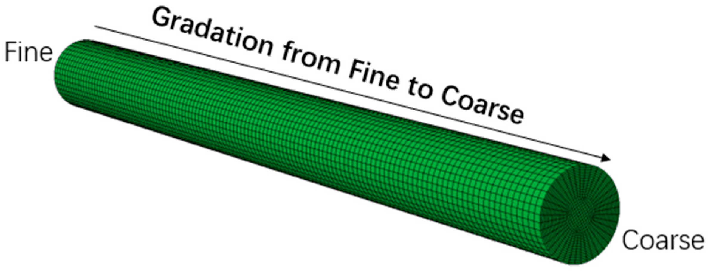
When applying the CEL method, the extruded material was modeled as an Eulerian body. The EC3D8R element type was used for meshing, with mesh refinement applied to the initial position of the extruded material to ensure computational accuracy, as shown in
Figure 3.
2.3. Material Parameters and Boundary Conditions
The parameters of the barrel, screw and extruded material used in the numerical simulation are shown in
Table 1 and
Table 2.
Based on the extrusion process, the boundary conditions were defined according to the following fundamental assumptions.
The friction coefficient is assumed to remain constant and independent of pressure;
Variations in density are neglected;
Only the static pressure of the material due to gravity at the thread starting point below the hopper is considered, whereas the gravity of the material inside the screw channel is negligible compared with other forces;
The solid plug is assumed to maintain tight contact with all three walls of the screw channel as well as the internal surfaces of the machinery.
Due to the significant stiffness difference between the extruded material and the screw/barrel, hard contact conditions were defined. This setup not only eliminates the need to calculate metal surface deformation but also satisfies the no-slip wall condition for non-Newtonian fluids. In the boundary condition settings, the barrel, as a fixed structure of the extruder, was modeled as a fixed support. Screw rotation was specified as the primary driving force for extrusion, with the rotational speed serving as one of the parameters for subsequent analysis. Thermal boundary conditions were imposed through predefined fields, assigning temperatures to both the extruded material and the different barrel sections. The inner wall of the barrel was defined as a constant-temperature boundary to simulate the heating effect of external heating bands. Frictional heat generation was automatically considered at the contact interface between the rotating screw and the polymer melt, representing the internal shear-induced heating during extrusion. The outlet surface was set as a controlled temperature boundary to investigate the influence of outlet temperature on the flow and stress fields.
In the thermal boundary conditions, heat input was considered from two sources: (i) constant heating provided by external barrel heaters, and (ii) frictional heating generated by the interaction between the rotating screw and the melt. These two heat sources act together to govern the temperature distribution of the melt during extrusion.
In the numerical model, the UHMWPE melt was treated as a non-Newtonian fluid with viscosity dependent on shear rate and temperature. So, in the material definition, a temperature-dependent Carreau rheological constitutive model was set up to describe the flow behavior of UHMWPE, thereby reflecting its nonlinear viscous characteristics during the high-temperature extrusion process.
4. Results and Discussion
For polymer materials, the extrusion molding process involves solid–liquid phase transitions, often accompanied by complex phenomena such as plasticization and flow. The melt flow and deformation exhibit non-Newtonian characteristics, meaning that the proportionality coefficient between shear stress and shear rate is not constant but is instead influenced by factors such as pressure, processing temperature, and material properties.
Ultra-high molecular weight polyethylene undergoes three stages in the extrusion process, namely solid feeding, melt flow, cooling and forming. The complete flow-state contour is shown in
Figure 7. Material particles enter the barrel through the hopper and are subjected to gradually increasing stress. Driven by the high-speed rotation of the screw and heating from the barrel heaters, the polymer gradually melts, forming a viscous melt that flows toward the extrusion outlet under screw propulsion. This process is accompanied by the synchronous transfer of stress concentration zones. Finally, the extruded melt is uniformly applied to the mold, where it cools and solidifies, with the stress gradually decreasing to zero.
During the extrusion process, the outlet temperature and screw speed are the primary influencing factors. Ultra-high molecular weight polyethylene (UHMWPE) has both a higher molecular weight and viscosity, and its forming temperature is higher than that of conventional polyethylene (PE) materials. According to studies on the characteristics of UHMWPE by relevant researchers [
38,
39], when the processing temperature exceeds 220 °C, crystal dislocations and an increased number of defects are generated, leading to a reduction in mechanical properties. In addition, stress levels exceeding 20 MPa may cause melt fracture. Investigations into the production practices of pipe manufacturers have shown that, in actual production, the barrel temperature is typically set at around 180 °C to achieve better forming quality. Based on these considerations, six outlet temperature conditions were selected: 170 °C, 175 °C, 180 °C, 185 °C, 190 °C and 195 °C. Screw speed also directly affects the thickness uniformity of the liner layer, surface smoothness and material density. For high-viscosity materials, screw speed is usually kept lower. Therefore, six screw speed conditions were set: 0.16, 0.20, 0.32, 0.48, 0.64 and 0.80 rad/s. After theoretical calculations, the final working condition table for outlet temperature and screw speed was established, as shown in
Table 4.
4.1. Influence of Temperature
Considering that the temperature field directly affects the quality of pipe forming, the extrusion process at the outlet was analyzed.
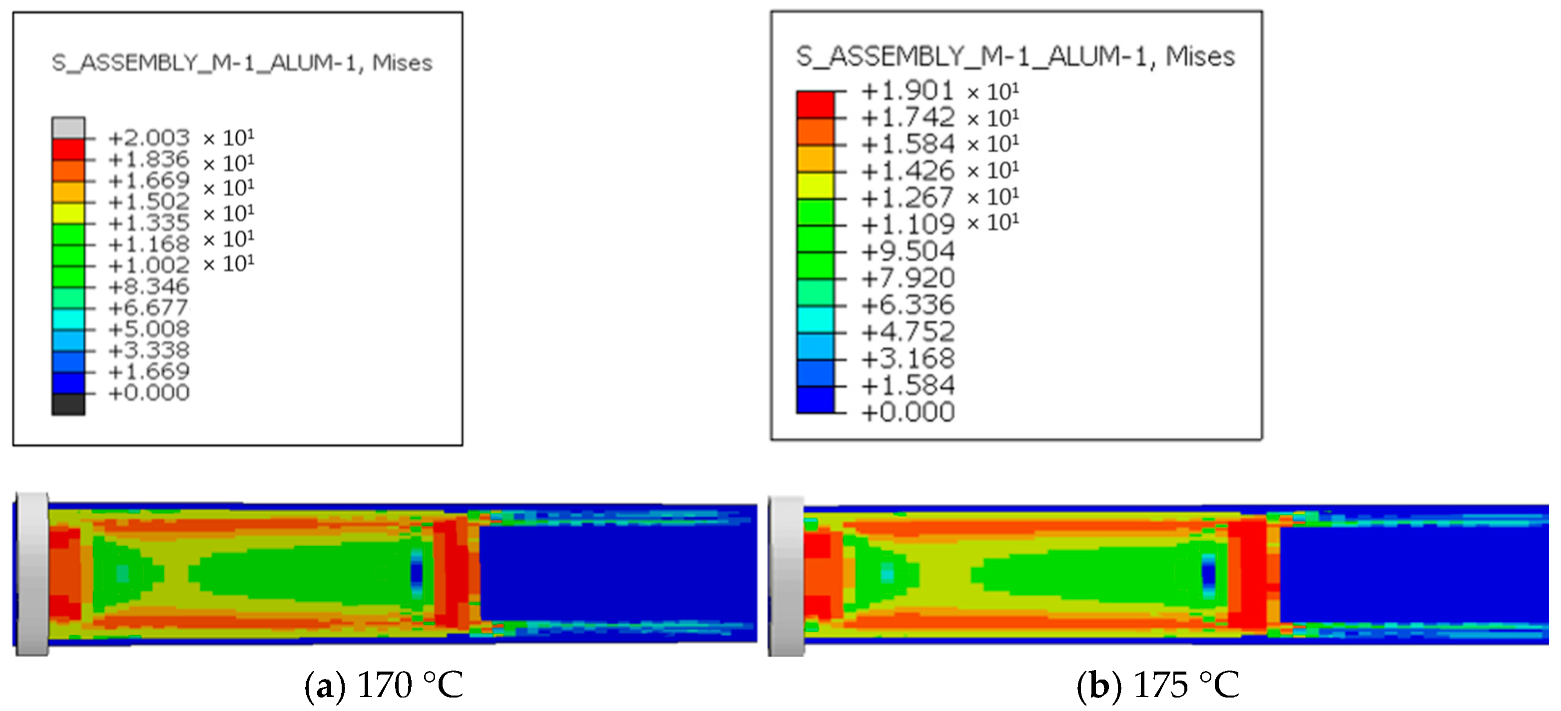
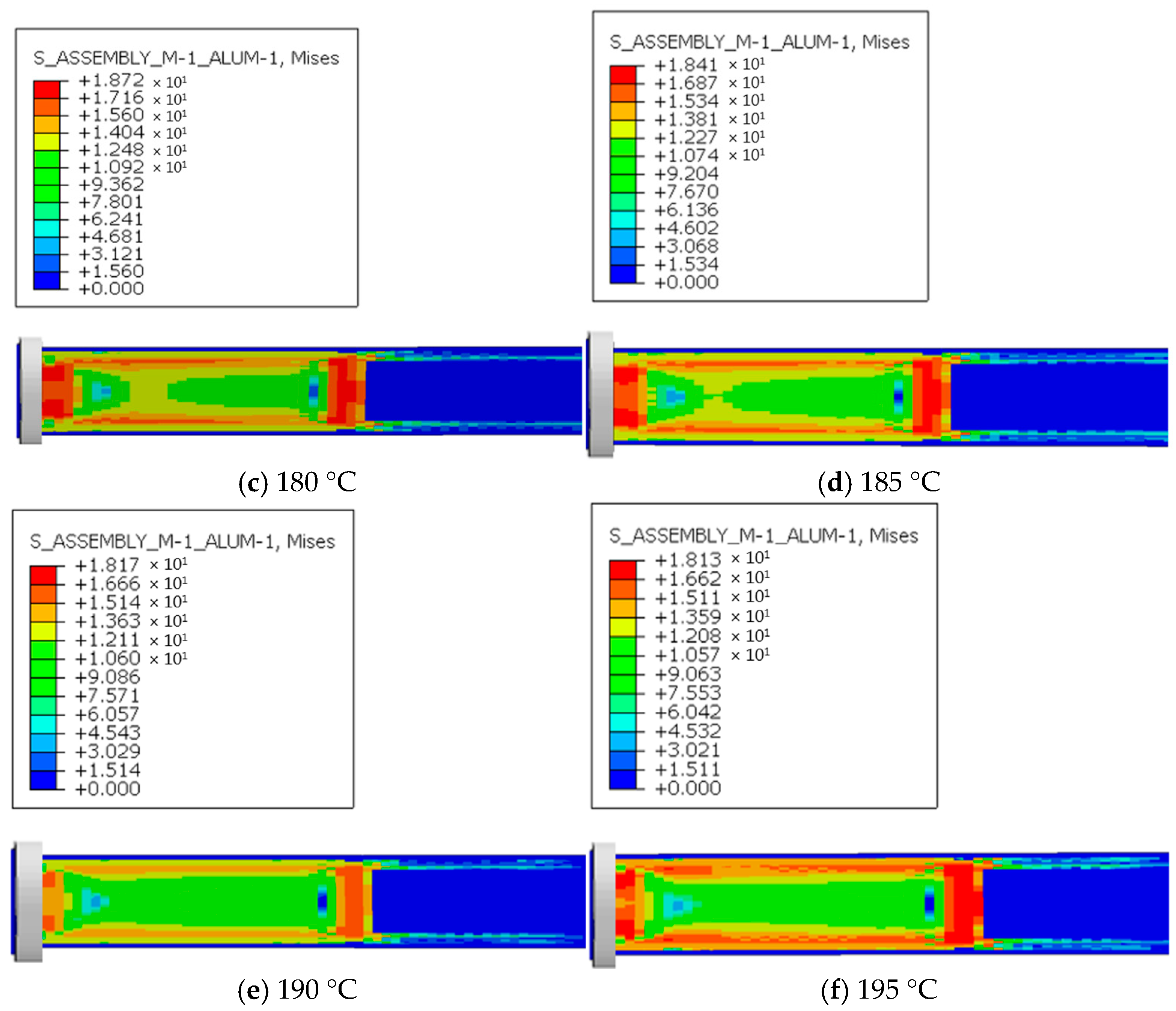
Figure 8 shows the stress distribution during extrusion under six outlet temperature conditions. At the outlet stage, the extruded material experiences relatively high stress, which is mainly concentrated in the region that has not yet been extruded, with the maximum stress reaching 17–20 MPa. After the pipe is formed, this stress is released and gradually decreases to zero. The concentrated stresses at the die exit correspond to local tensile and shear stress peaks caused by abrupt changes in flow velocity and temperature gradients. These localized stresses can exceed the critical yield strength of UHMWPE in the molten or semi-solid state, resulting in micro void formation and molecular chain slippage near the surface. During long-term service under abrasive slurry transport and cyclic pressure fluctuations, these microstructural defects can evolve into fatigue microcracks. Such microcracks serve as crack initiation sites, which propagate under the combined effects of abrasion and corrosion, leading to progressive liner degradation and reduced service life.
A comparison of the six temperature conditions shows that at 170 °C, the maximum stress reaches 20.03 MPa, and the material may suffer from reduced fluidity or even fracture due to stress concentration. For every 5 °C increase in outlet temperature, the maximum stress decreases by approximately 0.3–1 MPa. As the outlet temperature continues to rise, the maximum stress is reduced to a safe range, although the rate of reduction gradually diminishes. The reason for this phenomenon is that, before the pipe is fully formed, the material remains in close contact with the screw head of the extruder, which generates resistance to screw rotation. The material directly in front of the screw creates the greatest resistance, producing positive pressure. Within the extruder, the polymer melt is in a viscous flow state, and its relatively high viscosity generates significant resistance to screw motion. This resistance increases with screw speed relative to the melt. After the material cools and solidifies, the formed pipe maintains only tangential friction with the screw, with short contact time and small contact area. Since there is no further compression between the screw and the material, stress concentrates in the unextruded portion at the outlet. As the outlet temperature increases, the viscosity of the extruded melt decreases. According to Newton’s law of internal friction, under the same relative speed between the screw and the melt and the same sleeve conditions, friction decreases with lower viscosity, thereby reducing stress.
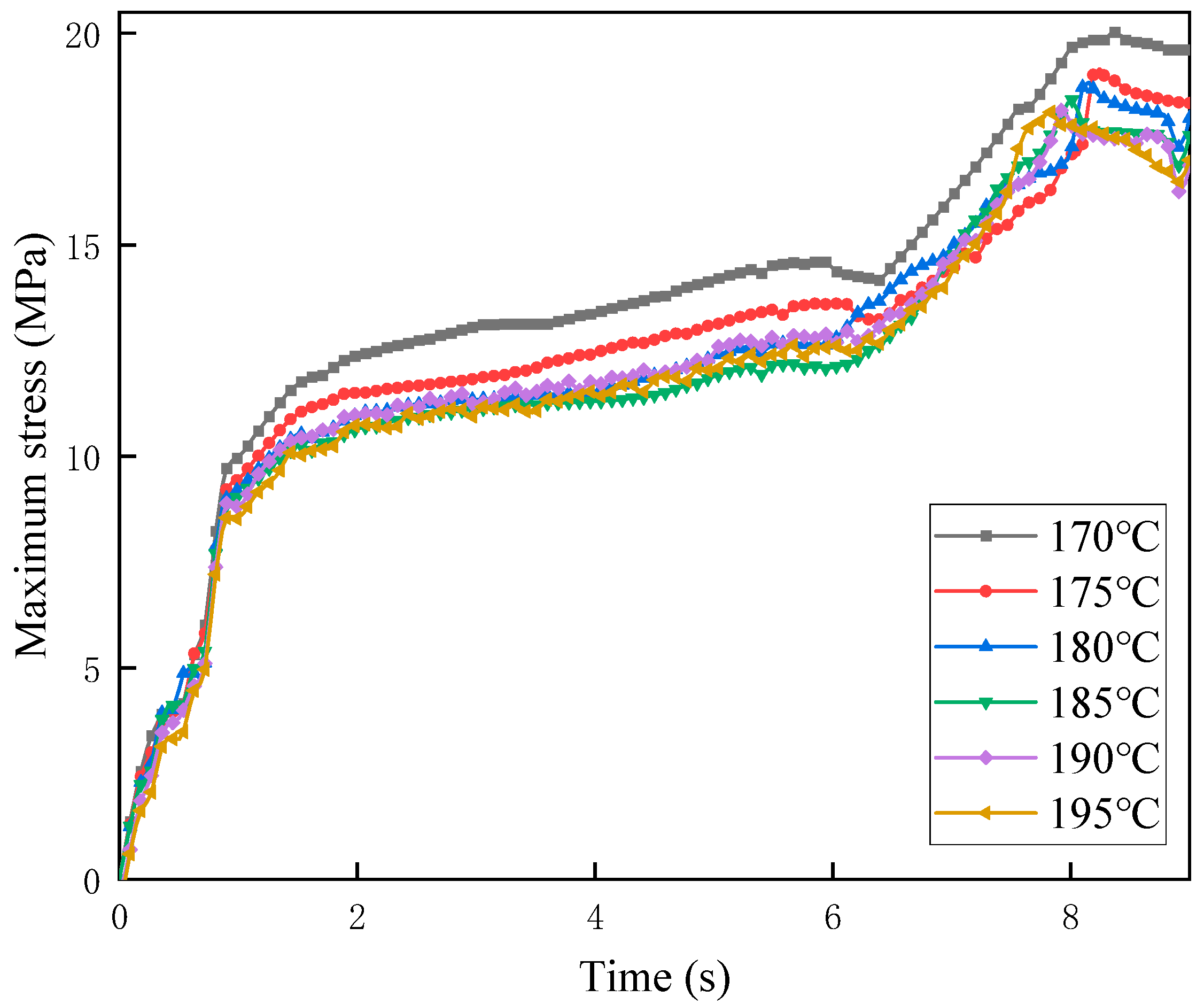
Figure 9 shows the maximum stress versus time curves under six outlet temperature conditions. The results indicate that the overall trends of maximum stress variation over time are similar, but the stress increase rate under 170 °C is significantly higher than that under the other temperature conditions. In the first 2 s, corresponding to the compression phase, stress increases sharply. This is followed by the extrusion forming phase (2–6 s), during which stress rises more gradually. After 6 s, stress again increases sharply and then stabilizes around 8 s at its maximum value. When the screw is not yet engaged with the melt, the stress remains at zero. As the screw compresses the material, interaction forces between the screw and melt increase, causing the steep stress rise observed in the first 2 s. Because the velocity gradient increases substantially but remains identical across different temperatures, the stresses are equal during this initial period. During material conveying (2–6 s), the resistance of the extruded melt increases, slowing screw acceleration and resulting in gradual stress growth. As cooling and forming occur, higher temperatures lower material viscosity and resistance while enhancing screw acceleration. This leads to a rapid stress increase between 6 and 8 s, which diminishes as the temperature rises, before stabilizing near 8 s. At higher temperatures, the maximum stress occurs earlier because increased molecular chain mobility accelerates the release of elastic energy stored during die swell.
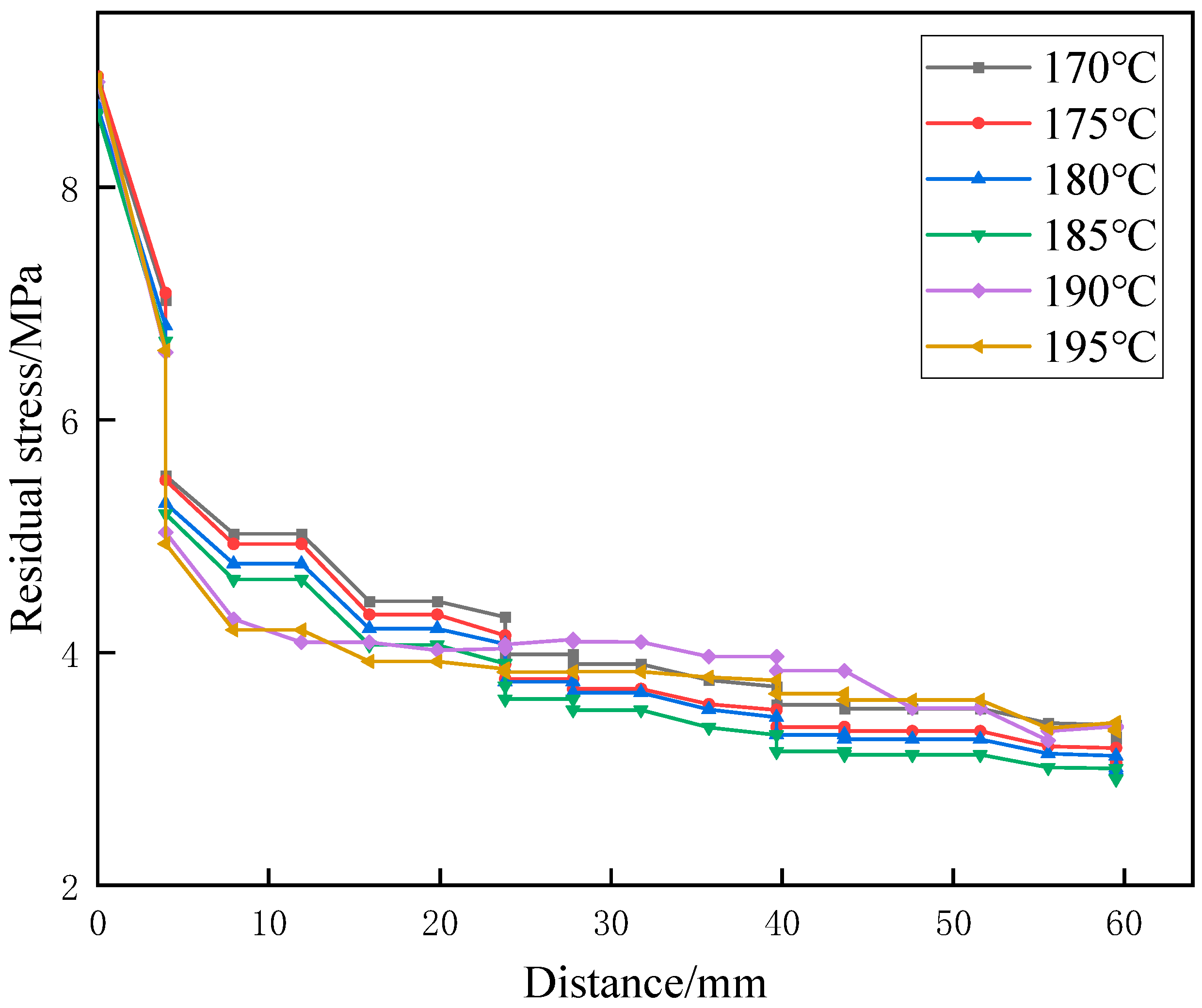
Figure 10 shows the residual stress distribution curves of the extruded parts under six temperature conditions. The results indicate that residual stress gradually decreases with increasing distance from the extrusion outlet. The earlier extruded parts exhibit lower residual stress, while the regions near the outlet retain relatively high residual stress, which decreases rapidly as extrusion progresses. This phenomenon occurs because the material undergoes rapid cooling and structural relaxation after extrusion. The molecular chains near the outlet have not fully completed orientation recovery and stress release, thus retaining higher residual stress. As the distance from the outlet increases, the molecular chains undergo further rearrangement and relaxation, causing the residual stress to gradually dissipate. A comparison of the six conditions shows that as the temperature increases, the residual stress level at the same position decreases, which is related to the earlier occurrence of maximum stress. Therefore, appropriately increasing the temperature can effectively reduce residual stress and improve the dimensional stability and mechanical properties of extruded products. However, when the temperature exceeds 190 °C, the reduction in residual stress with increasing distance from the extrusion outlet becomes significantly smaller. As a result, the residual stress levels at the far end of the outlet remain higher compared with those under lower temperature conditions. At this stage, further increasing the temperature can no longer effectively release the residual stress in extruded parts.
Heat flux refers to the thermal energy transferred through a unit area per unit time. Within reasonable limits, increasing heat flux can maintain melt temperature, reduce material viscosity, decrease flow resistance, and thereby improve forming quality. By analyzing the heat flux of the material during processing, temperature variations during pipe forming can be investigated.
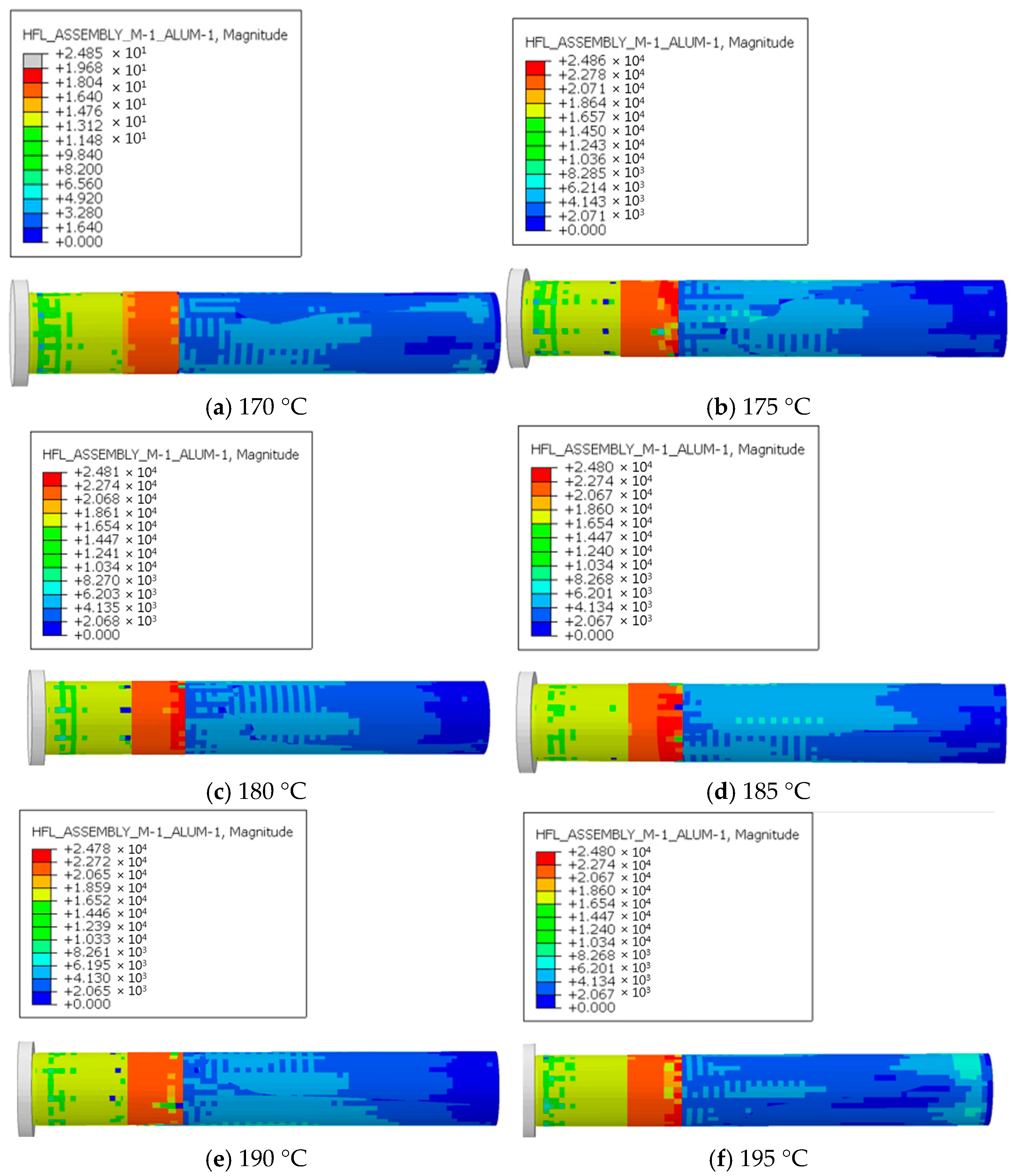
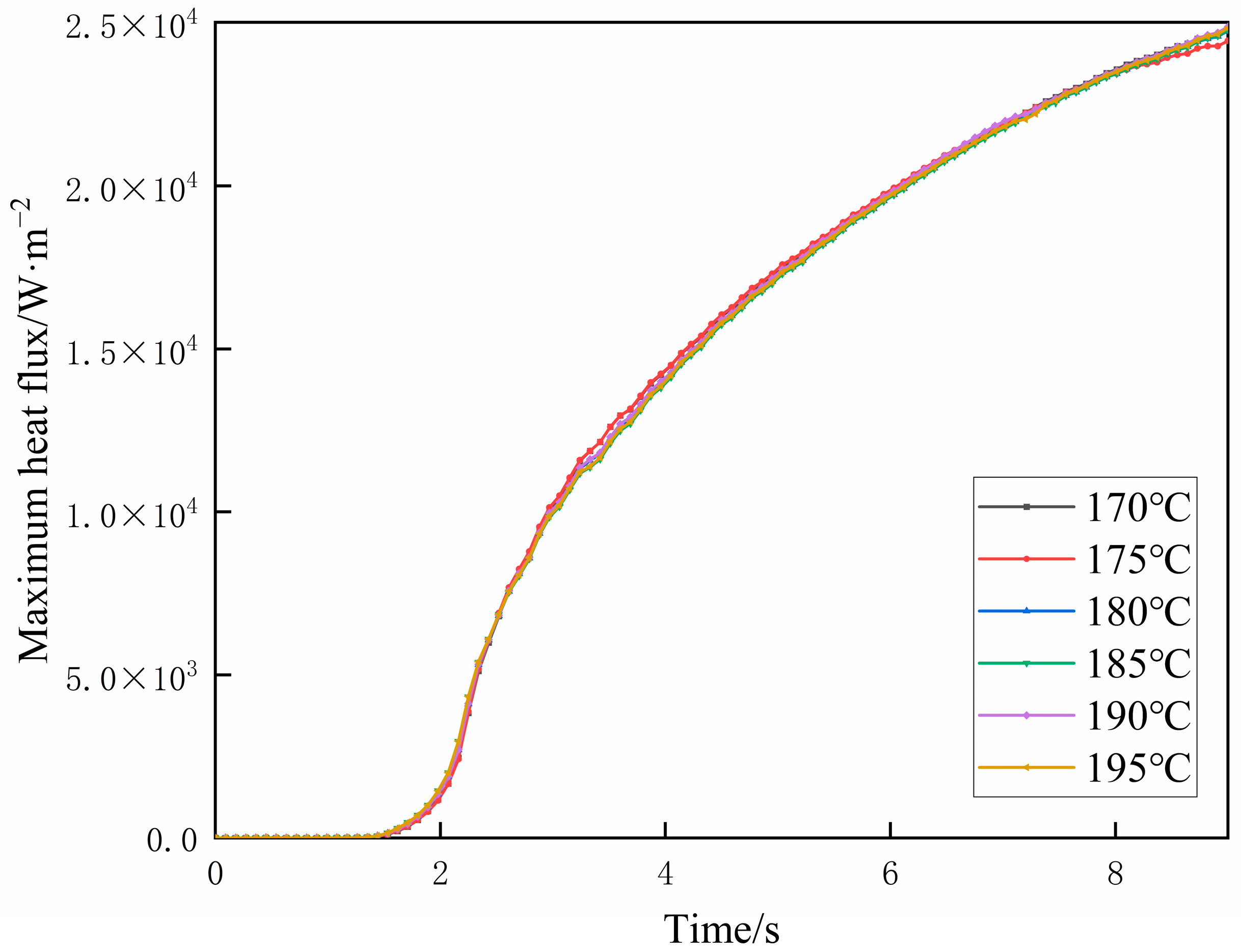
Figure 11 presents the heat flux distribution during extrusion under six outlet temperature conditions. At the outlet stage, heat flux is mainly concentrated near the outlet and around the pipe forming region. After pipe formation, the heat gradually decreases. A comparison of the six conditions shows that as outlet temperature increases, the maximum heat flux remains nearly constant at approximately 24,000 W/m
2. This occurs because the interaction between the extruded material and the screw is greatest at the outlet. The force exerted by the screw is also concentrated there, so the work performed by the screw and the corresponding heat generation are primarily localized at the outlet. Compared with the heat changes caused by temperature variations, the heat generated by screw work is much greater. Therefore, the maximum heat flux remains essentially unchanged as the outlet temperature increases. Uniform regulation of heat flux ensures stable temperature gradients within the UHMWPE melt, which directly influences polymer chain mobility and crystallization kinetics. When the heat flux is evenly distributed, molecular chains orient and crystallize uniformly along the flow direction, forming a dense and homogeneous microstructure with fewer amorphous regions and interfacial defects. In contrast, excessive local heat flux or uneven thermal distribution can produce thermal stresses and nonuniform cooling rates, resulting in microvoids and weak inter-lamellar regions. These regions exhibit lower mechanical integrity and higher free volume, which can serve as preferential corrosion initiation sites when the liner is exposed to seawater and mineral slurry. Therefore, controlling the heat flux during extrusion not only improves dimensional stability and surface quality during manufacturing but also enhances the long-term corrosion resistance and structural reliability of the liner in deep-sea service.
The time-history curves of maximum heat flux under six outlet temperature conditions are shown in
Figure 12. The variations in heat flux over time are essentially consistent across all six conditions. During the first 2 s, corresponding to the compression phase of the extruded material, the heat flux increases rapidly. After extrusion begins, the heat flux continues to increase with time, but the rate of increase gradually decreases. A comparison of the six outlet temperature conditions shows that with increasing temperature, the variation range of heat flux extremes exhibits only minor differences.
4.2. Influence of Screw Speed
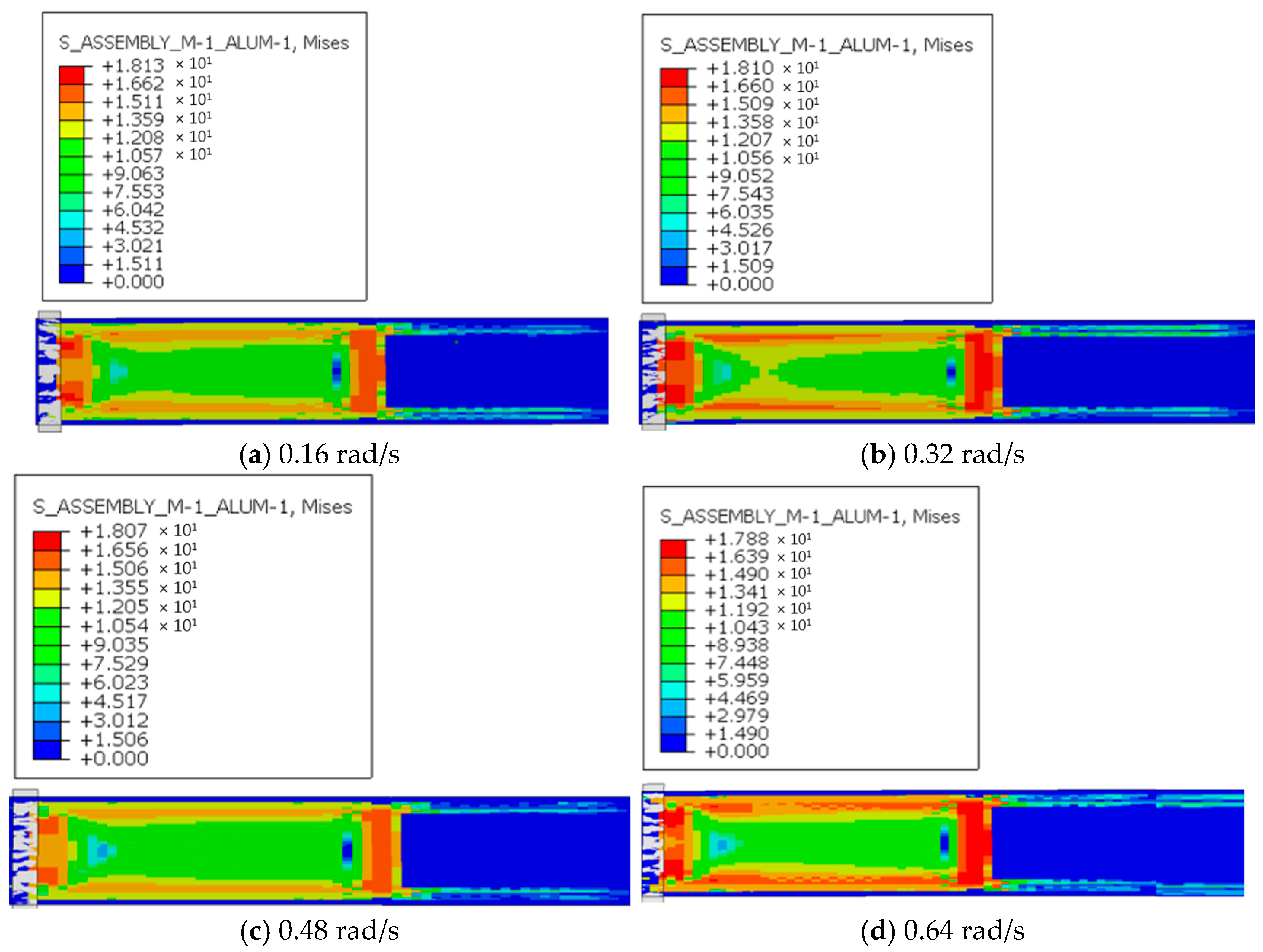
Figure 13 shows the stress distribution during extrusion under four screw speed conditions. At the outlet stage, the stress of the extruded material is mainly concentrated in the unextruded portion and at the forming outlet. After pipe formation, the stress gradually decreases. A comparison of the four conditions shows that as screw speed increases, the maximum stress varies only slightly, remaining essentially around 18 MPa. This phenomenon occurs because the stress generated in the extruded material primarily originates from the resistance between the material and the screw. According to Newton’s law of viscosity, this resistance is mainly determined by the velocity gradient of the melt between the screw and the barrel. The velocity gradient is largely governed by the conveying speed of the extruded material, defined as its travel speed relative to the screw. Since screw speed does not affect the conveying speed of the extruded material, it consequently does not influence the velocity gradient of the melt. Therefore, changes in screw speed do not lead to significant variations in maximum stress.
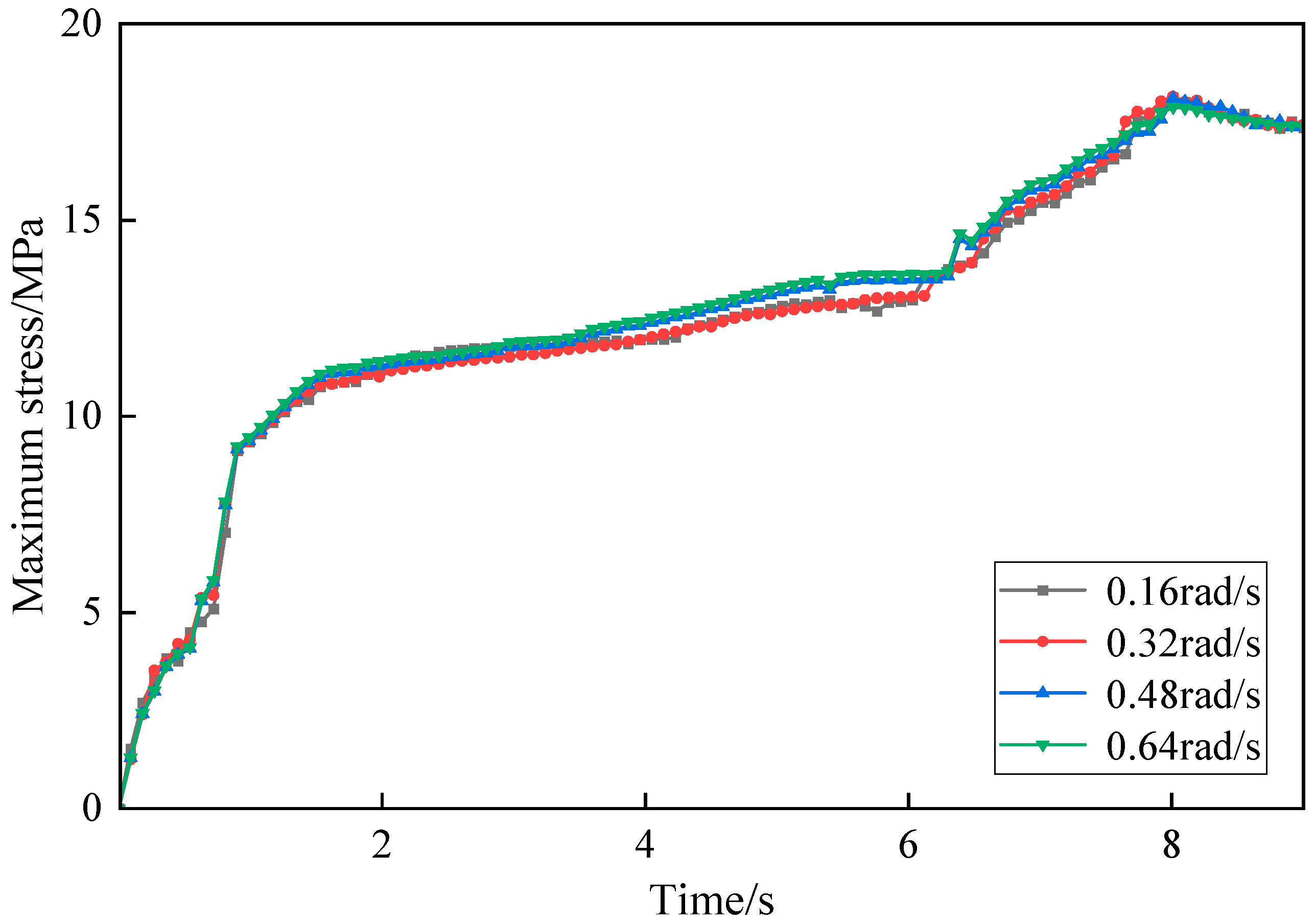
Figure 14 shows the time-history curves of maximum stress under four screw speed conditions. The variation in maximum stress over time is generally consistent across all four conditions. During the first 2 s, corresponding to the compression phase of the extruded material, stress increases sharply. This is followed by the extrusion forming phase, during which stress rises more gradually, reaching its maximum value and stabilizing around 8 s. A comparison of the four screw speed conditions indicates that as time increases, maximum stress grows with screw speed, although the stabilized extreme values differ only slightly.
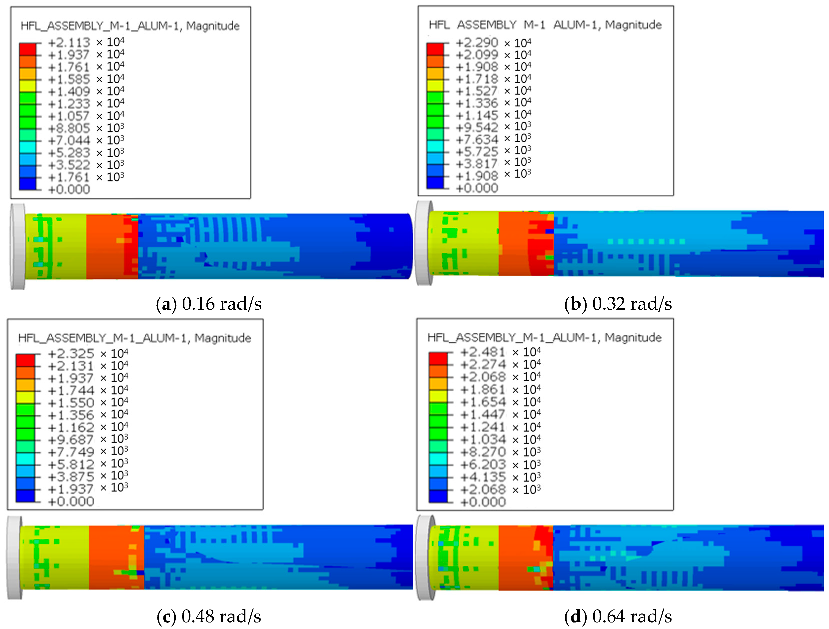
Figure 15 shows the heat flux distribution during extrusion under four rotational speed conditions. At the outlet stage, the heat flux is mainly concentrated in the external annular region of the outlet, with larger values observed both before and after pipe formation. After the pipe is formed, the heat flux gradually decreases. A comparison of the four conditions indicates that the maximum heat flux increases significantly with screw speed. This phenomenon occurs because the primary heat source for the extruded material is the work performed by the screw on the melt contact surface. At higher screw speeds, the relative displacement between the screw and the contacted melt surface is greater within the same time period. Consequently, more work is performed, resulting in higher power transfer from the screw to the melt, which generates additional thermal energy and leads to a sharp increase in heat flux.
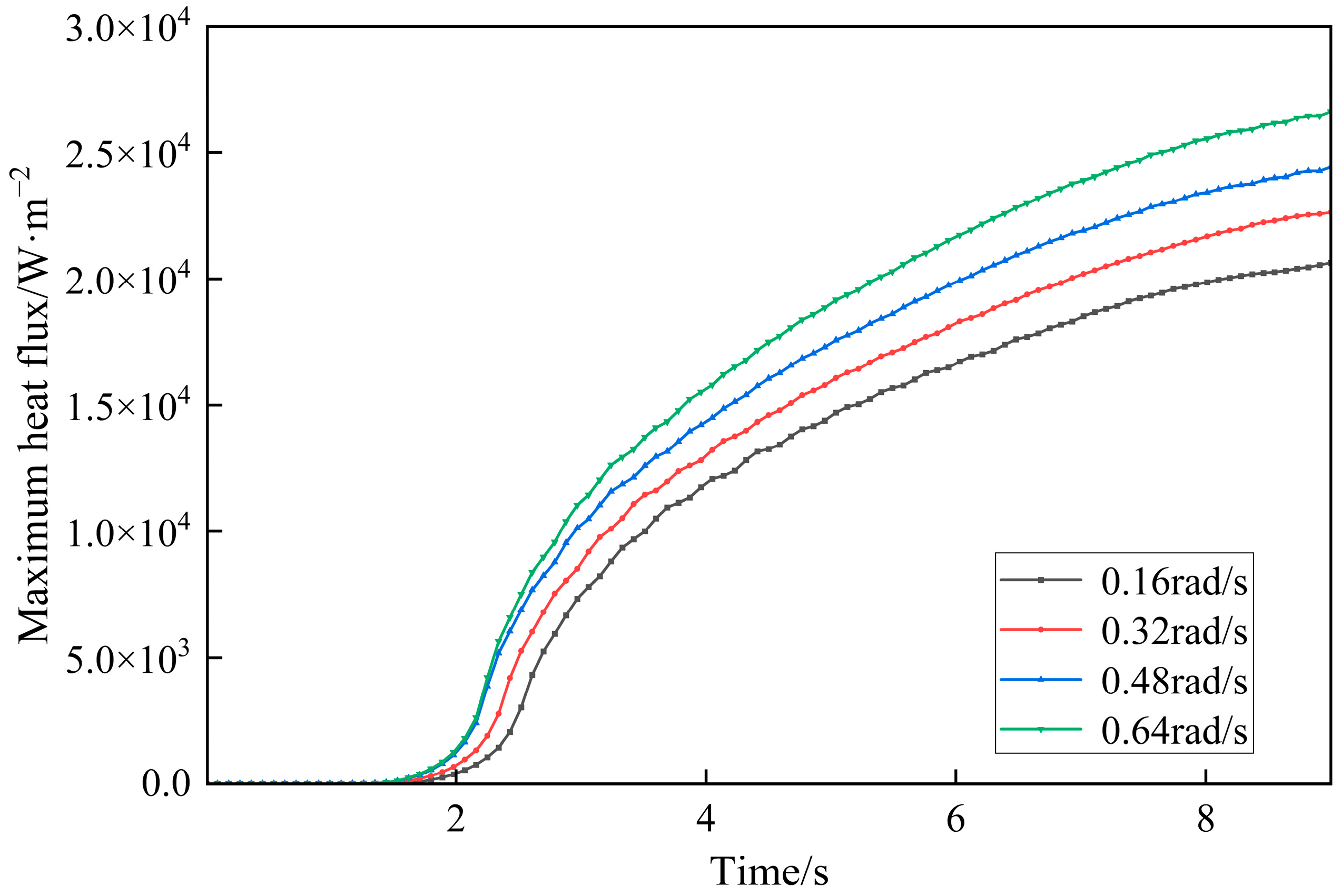
Figure 16 shows the time-history curves of maximum heat flux under four screw speed conditions. The variations in heat flux are generally consistent across all four conditions. During the first 2 s, corresponding to the compression phase of the extruded material, the heat flux remains essentially unchanged. As material compression begins, the heat flux increases significantly, although the rate of increase gradually decreases until stabilization. Notable differences in heat flux values are observed among the different screw speeds. A comparison of the four screw speed conditions indicates that higher screw speeds lead to significantly greater heat flux, with higher extreme values and more pronounced overall variations. At the beginning of extrusion, material contact at the screw–outlet interface is minimal, which results in negligible heat generation and an almost constant heat flux during the initial compression phase. As more material enters the extruder, contact with the screw gradually increases until full contact is established, leading to a sharp rise in heat generation. With higher screw speeds, the power input is greater, and the heat flux correspondingly increases. Once extrusion stabilizes under full screw–material contact, differences in heat flux primarily arise from variations in screw speed, which cause different levels of heat generation through work conversion over the same time period. Proper control of screw speed mitigates thermal degradation of UHMWPE during extrusion, thereby improving the chemical stability of liners against seawater and corrosive minerals during long-term operation. Although the growth rate of heat flux decreases over time, significant differences remain across the different screw speed conditions.


