Article

Coupled Burst and Fracture Failure Characteristics of Unbonded Flexible Riser Under Internal Pressure and Axial Tension

1
School of Mechanical and Electric Engineering, Soochow University, Suzhou 215131, China
2
Naval Research Institute (NVRI), Beijing 100161, China
*
Authors to whom correspondence should be addressed.
These authors contributed equally to this work.
J. Mar. Sci. Eng. 2025, 13(10), 1866; https://doi.org/10.3390/jmse13101866
Submission received: 12 August 2025 / Revised: 20 September 2025 / Accepted: 24 September 2025 / Published: 26 September 2025
(This article belongs to the Special Issue Advanced Research in Flexible Riser and Pipelines)

Abstract

Unbonded flexible risers, which can experience large bending deformation, are key equipment in advancing deep-sea exploration for marine resources. However, the riser experiences coupled loading effects from ocean environment. This results in complex response characteristics, leading to potential damage or even destruction. By presenting an analytical–numerical framework, this study uncovers the mechanism underlying the coupled failure of the pressure- and tensile-armor layers, furnishes a new tension–pressure coupled failure boundary for the ultimate-limit-state design of deep-water risers, and supplies the corresponding theoretical verification. Firstly, based on the axisymmetric load assumption, a theoretical model is proposed based on principle of functionality; afterwards, the failure model is defined by considering the material elastoplasticity. Secondly, a full-layered numerical model with detailed geometric properties is established; meanwhile, a simplified 7-layer model without a carcass layer is constructed for comparison. Finally, after verified through experimental data and interactive verification of theoretical and numerical methods, the simplified numerical model is proved to have calculation accuracy and validity. The characteristics are studied by the proposed methods. The comparison results show that the pre-applied internal pressure has limited influence on the axial stiffness of unbonded flexible rise. The initial axial tension would enhance the anti-burst failure ability of unbonded flexible riser, the failure pressure increases by 35% when the tensile force is 500 kN.

1. Introduction

Riser systems are pipelines that connect surface facilities to submarine equipment, and has the functionality to with stand high pressure, corrosive media and harsh environmental loads to ensure the safe transportation of marine oil, gas and mineral resources. Among the many different types of production risers, unbonded flexible risers possess several merits, including the capacity to withstand large deformations, resistance to corrosion, simplicity in installation, and recyclable characteristics, and are prioritized or mandatory for the extraction of offshore oil and gas resources. An unbonded flexible riser is typically assembled of a series of functional interlayers (see Figure 1), which can be divided into helical layers and cylindrical layers according to the geometric properties.
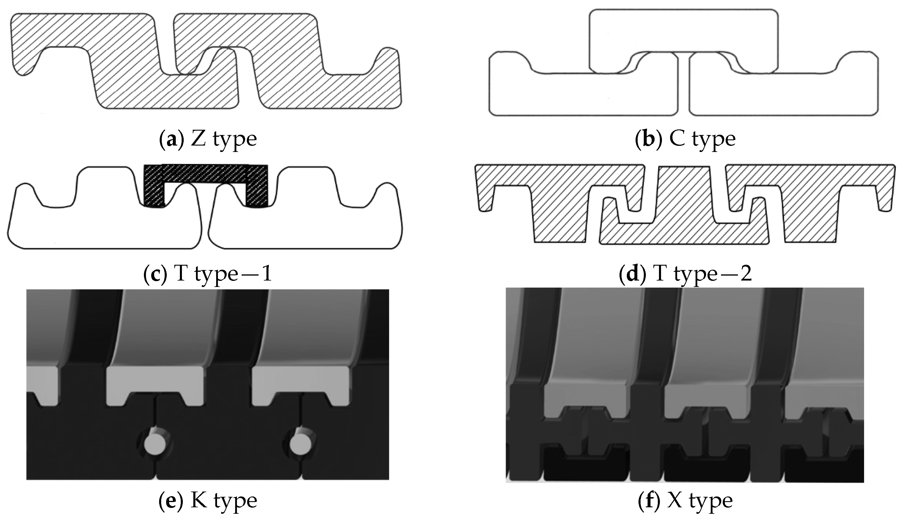
Among the different type of interlayers of unbonded flexible riser, the helical layers are the main load-bearing structures, and the direct cause of the special mechanical properties of the unbonded flexible riser. The tensile-armor layer is the most crucial element of the unbonded flexible riser, which mainly provides axial stiffness, is subjected to axial tension and torque about the axial direction, and ensures the riser’s safety due to self-weighting and other environmental loads. The pressure-armor layer constitutes steel self-locking structures with high laying angles and irregular cross-section geometries, typically ‘Z’ type (see Figure 2a), ‘C’ type (see Figure 2b), and ‘T’ type (see Figure 2c,d) et al., which mainly provide radial stiffness and support the internal pressure-armor layer. As with the asymmetric cross-sectional properties of the pressure-armor layer, the burst failure manifests as local stress concentration and structural damage when the internal pressure surpasses the ultimate bearing capacity. However, when exposed to a harsh marine environment, the failure of the riser system occurs from time to time, especially for the unbonded flexible riser, where coupled failure physics might occur, causing major environmental accidents such as offshore oil spill, bringing immeasurable economic and ecological losses [1]. Reliable prediction of their failure behavior is therefore essential for safe, economic, and sustainable deep-water oil and gas production. Recent advances in multifunctional materials offer potential routes to enhance layer durability: for example, hybrid systems based on thermally stable amorphous porous silicon nanoparticles have demonstrated improved thermal and chemical stability [2,3], while nano-fibrous scaffolds have exhibited tailored antimicrobial and repair functionalities [4,5]. Although these material concepts have yet to be transferred to riser technology, they highlight future possibilities for mitigating the coupled failure physics identified above.
Predicting the unbonded flexible risers’ behavior commonly involves using numerical and theoretical research techniques. Experimental methods can accurately indicate unbonded flexible riser’s mechanical features and help in understanding their cross-sectional mechanical properties; however, experimental studies are costly, leading to a scarcity of experimental data due to the intricate structure of the risers. From the published experimental data related to unbonded flexible risers, Witz [6] experimented on a 2.5-inch, 8-layer unbonded flexible riser under axial tension and torque loads. Yue et al. [7] experimentally confirmed the mechanical characteristics of unbonded flexible risers under axial tension within shallow marine areas. Vargas-Londoño et al. [8] discovered in later experimental studies that the bearing capacities of various spiral steel strips within the tensile-armor layer exhibit inconsistencies. Zhou et al. [9] also found that there is a nonlinear correlation between the load and the strain under axisymmetric load through experimental research and analysis of the anti-friction zone in the unbonded flexible riser.
To the date, numerical simulation and theoretical analysis remain the core methods for exploring the mechanical properties of unbonded flexible risers. The theoretical models of unbonded flexible risers mainly consider the stress–strain relationships of each layer structure separately, and also take into account the inter-layer contact interactions [10]. Among them, Kebadze [11] divided all layer structures of unbonded flexible risers into different layers, including cylindrical shell layers and helical layers. He has contributed significantly to research into the theoretical model of such risers under axisymmetric loads. Subsequently, Dong [12] fully considered the spatial geometric relationships of the helical layers and made corresponding corrections to Kebadze’s model. In addition, with Kebadze’s theoretical model as the foundation, helical layer structures with complex cross-sectional geometries—including the carcass layer and tensile-armor layer—were converted by Bahtui [13] into orthotropic cylindrical shells. However, theoretical approaches have limitations in capturing complex load behavior.
With regard to numerical analysis, Ren et al. [14] established a finite-element method-based model to investigate stress distribution in damaged tensile-armor layers of unbonded flexible risers under elastic tension. Cornacchia et al. [15] conducted numerical simulations to examine the tensile mechanical characteristics of flexible pipes. De Sousa et al. [16] studied the structural deformational of damaged tensile-armor layers under pure axial tension. Under individual loads, the mechanical properties of tensile-armor layers were primarily the focus of these studies. Recent investigations has increasingly directed their attention toward the mechanical response of unbonded flexible risers subjected to combined loading conditions. Liu et al. [17] found that effective tension enhances the capacity of unbonded flexible risers to withstand bending moments when studying pressure-armor layers under coupled loads. Jiang et al. [18] and Wang et al. [19] examined the mechanical behavior of unbonded flexible risers under combined loads. Under axial tension and internal pressure, Sun et al. [20] used theoretical and numerical methods to predict the structural stiffness of risers. Tang et al. [21] investigated stress–strain responses and failure modes within tensile-armor layers of unbonded flexible pipelines subjected to multi-axial loading conditions. However, these studies did not delve into the failure characteristics of the armor layers.
In terms of failure characteristics, Yoo et al. [22] evaluated the ultimate strength and failure modes of unbonded flexible risers under axial tension and compression, but they did not investigate the role of internal pressure in tensile failure under such loading. Berge et al. [23] and Antoine et al. [24] examined the influence of initial manufacturing defects on tensile failure, yet the underlying mechanism remains largely unexplored. Ebrahimi et al. [25] employed finite-element analyses to characterize tensile-armor failure under axisymmetric loading, but their study was conducted without external pressure and thus lacks a corresponding investigation. Similarly, Zhu et al. [26], Kamaya et al. [27] and Neto et al. [28] concentrated solely on predicting burst pressure without addressing the factors that govern failure. Zeng et al. [29] proposed a finite-element-based method for burst-pressure evaluation, yet they did not examine how axial tension influences burst failure. Liu et al. [30] and Wei et al. [31] incorporated bending–internal-pressure coupling, yet they still ignored axial tension, leading to a potentially inaccurate identification of the burst initiation site and propagation path.
Despite progress in research, under axial tension and internal pressure, the mixed failure characteristics of unbonded flexible risers have not been thoroughly explored in the existing literature.
According to a conventional 2.5-inch unbonded flexible riser model that considers the elastoplastic behavior of the steel armor layer, this paper discusses the mixed failure characteristics of the riser’s pressure-armor layer and tensile-armor layer under the coupling action of complex loads. The organization of the present paper is outlined below. In Section 2, the theoretical model established in this paper is explained. Leveraging the work–energy reversibility principle, this study derives an analytical framework for both the helical strip component and the cylindrical shell structure subjected to axisymmetric loading conditions, explicitly accounting for material elastoplastic behavior. Section 3 details the development of the numerical simulation using ABAQUS (2022) and the specification of key simulation parameters. Section 4 rigorously assesses the accuracy of both the numerical simulation framework and the analytical formulation, alongside the validity of the simplified 7-layer abstraction. Subsequently, on the basis of the simplified 7-layer abstraction, this section systematically investigates the complex failure mechanisms within the armor system resulting from the concurrent application of axial tensile forces and internal pressurization. Then, on the basis of the simplified model, the mixed failure characteristics of the armor layer under the coupling action of axial tensile load and internal pressure are studied. This study provides a novel tension–pressure coupled failure boundary for the ultimate-limit-state design of deep-water risers, breaking through the single-load limitation of the existing literature and offering a theoretical basis for related engineering practice.

2. Theoretical Model of Mixed Failure in Unbonded Flexible Risers Under Axisymmetric Loads

Unbonded flexible risers are made up of multi-layer complex structures. Each layer has its own functional features, material properties and geometric cross-section characteristics. These layers interact with one another and contribute to the overall characteristics of the unbonded flexible riser [32]. Leveraging the geometric attributes of individual unbonded flexible riser strata, this research classifies layer structures into two broad structural families: cylindrical shell layers and helical layers.

2.1. Limitations of the Model

Given that the inter-layer gap in a new unbonded flexible riser is less than 0.05 mm, the energy dissipated by inter-layer friction is negligible, and the numerical model is only intended to predict the first-yield elastic limit, the theoretical model in this paper is obtained with the following theoretical assumptions:
  • Both ends of each layer are fixedly installed on the terminal device to form an integral whole, and it is postulated that the axial elongation rates of each layer are the same. It ensures that all layers are synchronized in axial deformation, so that the multi-layer structure can be regarded as a whole for mechanical analysis, which greatly simplifies the establishment of control equations.
  • The theoretical model does not consider the gap between layers in the initial calculation stage, so that the classical elastic mechanics theory can be applied to calculate the initial stress state.
  • The materials of each layer are homogeneous and change within the linear elastic range, permitting the application of the generalized Hooke’s law.
  • Neglect the initial defects formed in the production process. The aim is to analyze the performance of an idealized, flawless structure so as to establish a performance upper bound benchmark.
  • Neglect the impact of the boundary effect and consider that the thickness of each layer changes consistently along the pipe’s length and in the radial direction. It is beneficial to analyze the mechanical behavior of any cross-section of the pipeline independently without considering the influence of end constraints.
  • Ignore the energy caused by friction from the relative movement between the layers. It can simplify the derivation process of the energy method.
  • It is assumed that the pressure-armor layer can still support a certain level of internal pressure when it reaches yield stress, making the model closer to the actual engineering judgment.

2.2. Equilibrium Equations of Cylindrical Shell Layers Under Axisymmetric Loads

A cylindrical shell consists of the inner and outer sheath layers made of polymer materials. This structure serves primarily to segregate fluids inside and outside the riser, minimize inter-layer friction, and ward off wear on steel-layer components. For a more realistic description of the geometric shape and stress–strain characteristics, this paper takes into account the thickness change in the cylindrical shell layer and solves it based on the thick-walled cylinder theory. As shown in Figure 3, there is the cylindrical shell layer before and after deformation. It is assumed that the axisymmetric loads acting on the cylindrical shell layer include torque T , axial force F , and external and internal pressures P o and P i . The Cartesian coordinate system xyz represents the spatial position before deformation (the solid-line part), while the x′y′z′ coordinate system represents the spatial position after deformation (the dashed-line part). The corresponding variation amounts are expressed as the axial variation amount Δ L , the radial variation amount Δ R , the torsion angle Δ ϕ around the central axis z, and the thickness variation amount Δ t .
For homogeneous materials, γ = Δ ϕ / L , the calculation formula for the strain energy of the cylindrical shell layer, can be expressed as:
U = 1 2 ν ( σ 1 ε 1 + σ 2 ε 2 + σ 3 ε 3 + τ 12 γ 12 ) d ν = π 2 [ ( λ + 2 G ) ( ε 1 2 + ε 2 2 + ε 3 2 ) + 2 λ ( ε 1 ε 2 + ε 1 ε 3 + ε 2 ε 3 ) + G R m 2 γ 2 ] R o 2 R i 2 L
where the corresponding geometric strains include axial strain ε 1 , radial strain ε 2 , thickness strain ε 3 and torsional angle strain γ 12 , which are defined as follows, as well as the stress expressions in each direction:
ε 1 = Δ L L ε 2 = Δ R R m ε 3 = Δ t t γ 12 = R m Δ ϕ L σ 1   = λ e + 2 G ε 1 σ 2   = λ e + 2 G ε 2 σ 3   = λ e + 2 G ε 3 τ 12 = G γ 12
The calculation formula for the work performed by external forces is as follows, where Δ V i and Δ V o are the volume change amounts inside and outside the cylindrical shell, respectively:
W = F Δ L + T Δ ϕ + P i Δ V i P o Δ V o
Let the internal and external volumes before deformation be V i and V o , respectively, and let the volumes after being deformed by axisymmetric loads be V i and V o , respectively. According to the spatial geometric relation, we can obtain [11]:
  V i = π R i 2 L V o = π R o 2 L V i = π ( R i + Δ R Δ t 2 ) 2 ( L + Δ L ) V o = π ( R o + Δ R + Δ t 2 ) 2 ( L + Δ L )
According to Equation (3), Δ V i and Δ V o can be expressed as:
Δ V i = π R i + Δ R Δ t 2 2 ( L + Δ L ) π R i 2 L π ( 2 R i Δ R R i Δ t ) L + π R i 2 Δ L = π R i L ( 2 R m ε 2 t ε 3 + R i ε 1 )
Δ V o = π R o + Δ R + Δ t 2 2 ( L + Δ L ) π R o 2 L π ( 2 R o Δ R + R o Δ t ) L + π R o 2 Δ L = π R o L ( 2 R m ε 2 + t ε 3 + R o ε 1 )
Substituting Equations (4) and (5) into Equation (2), the expression for the external force work can be obtained:
W = ( F ε 1 + T γ ) L + π P i R i L ( 2 R m ε 2 t ε 3 + R i ε 1 ) π P o R o L ( 2 R m ε 2 + t ε 3 + R o ε 1 )
According to the principle of reversibility of work and energy [27] Π = W U = 0 , the following can be obtained:
U ε 1 = W ε 1 U γ = W γ U ε 2 = W ε 2 U ε 3 = W ε 3
The equilibrium equations of the cylindrical shell layer under axisymmetric loads are obtained from Equations (1), (6), and (7):
k 11 k 12 k 13 k 14 k 21 k 22 k 23 k 24 k 31 k 32 k 33 k 34 k 41 k 42 k 43 k 44 Δ L / L Δ ϕ / L Δ R / R m Δ t / t = F + π P i R i 2 π P o R o 2 T 2 π R m ( P i R i P o R o ) π t ( P i R i + P o R o )
where
k 11 = ν E A ( 1 + ν ) ( 1 2 ν ) + E A 1 + ν k 12 = k 21 = 0 k 13 = k 31 = ν E A ( 1 + ν ) ( 1 2 ν ) k 14 = k 41 = ν E A ( 1 + μ ) ( 1 2 ν ) k 22 = E 2 ( 1 + ν ) π 2 ( R o 4 R i 4 ) k 23 = k 32 = 0 k 24 = k 42 = 0 k 33 = ν E A ( 1 + ν ) ( 1 2 ν ) + E A 1 + ν k 34 = k 43 = ν E A ( 1 + ν ) ( 1 2 μ ) k 44 = ν E A ( 1 + ν ) ( 1 2 ν ) + E A 1 + ν

2.3. Equilibrium Equation of Helical Layer Under Axisymmetric Load

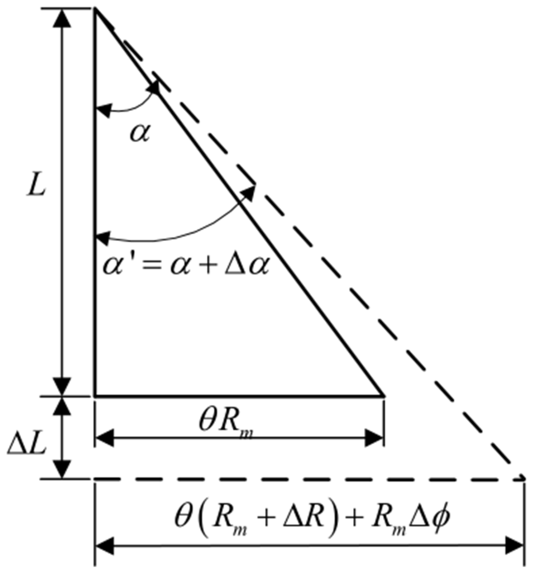
The helical layer serves as the primary structural configuration within unbonded flexible risers. This structural form includes the anti-friction layer made of polymer materials, as well as the carcass layer, the pressure-armor layer, and the tensile-armor layer made of metal materials. The force relationship and spatial geometric deformation of the spiral belt under the action of external loads are shown in Figure 4 and Figure 5.
According to Equation ε = ( S S ) / S , the strain of the spiral belt along its axial direction can be expressed as [11,32]:
ε a = cos 2 α Δ L L + R m sin α cos α Δ ϕ L + sin 2 α Δ R R m
When subjected to bending loads or large axisymmetric loads, the radial deformation of the spiral belt is sometimes non-negligible, so the cylindrical shell layer model is used for simulation [11,12]. For structures with regular rectangular cross-sections such as tensile-armor layers, the strain change in the thickness direction also needs to be considered, as shown in Figure 6 [11].
The strain of the spiral belt in the thickness direction can be expressed as [6]:
ε r = Δ t t
According to the calculation formula of strain energy for a single helical belt when considering the thickness change [33], the internal energy calculation formula for a helical layer with n helical belt can be obtained:
U = n U s   = 1 2 A n cos α L ( σ a ε a + σ r ε r ) d z   = 1 2 A n cos α E 1 ν 2 cos 4 α ε 1 2 + R m 2 sin 2 α cos 2 α γ 2 + sin 4 α ε 2 2 + 2 R m sin α cos 3 α ε 1 γ + 2 sin 2 α cos 2 α ε 1 ε 2 + 2 R m sin 3 α cos α γ ε 2 + 2 ν cos 2 α ε 1 ε 3 + 2 ν R m sin α cos α γ ε 3 + 2 ν sin 2 α ε 2 ε 3 + ε 3 2 L  
The volume changes inside and outside the tensile-armor layer can be equivalent to the volume changes in the cylindrical shell layer, and the work performed by external forces can be expressed by Equation (7). According to the principle of reversibility of work and energy, the equilibrium equation of the helical layer considering thickness changes under axisymmetric loads can be obtained [11]:
k 11 k 12 k 13 k 14 k 21 k 22 k 23 k 24 k 31 k 32 k 33 k 34 k 41 k 42 k 43 k 44 Δ L / L Δ ϕ / L Δ R / R m Δ t / t = F + π P i R i 2 π P o R o 2 T 2 π R m ( P i R i P o R o ) π t ( P i R i + P o R o )
where
k 11 = n A E 1 ν 2 cos 3 α k 12 = k 21 = n E A R m 1 ν 2 sin α cos 2 α k 13 = k 31 = n E A 1 ν 2 sin 2 α cos α k 14 = k 41 = n E A ν 1 ν 2 cos α k 22 = n E A R m 2 1 ν 2 sin 2 α cos α k 23 = k 32 = n E A R m 1 ν 2 sin 3 α k 24 = k 42 = n E A R m ν 1 ν 2 sin α k 33 = n E A 1 ν 2 sin 4 α cos α k 34 = k 43 = n E A ν sin 2 α 1 ν 2 cos α k 44 = n E A ( 1 ν 2 ) cos α

2.4. Overall Equilibrium Equations Under Axisymmetric Loads

Since the two ends of the riser are fixedly installed on the terminal devices, forming an integral whole, it is assumed that each layer has the same amount of change. Consequently, the equilibrium equations of the cylindrical shell layer and the helical layer, considering the thickness change under the action of axisymmetric loads, can be obtained:
  k 31 n Δ L L + k 32 n Δ ϕ L + k 33 n Δ R n R m n + k 34 n Δ t n t n = 2 π R m n ( P i n R i n P o n R o n )   k 41 n Δ L L + k 42 n Δ ϕ L + k 43 n Δ R n R m n + k 44 n Δ t n t n = π t p n ( P i n R i n + P o n R o n )
When the n-th layer and the (n + 1)-th layer are in contact under axisymmetric load, the spatial geometric relationship of adjacent layers can be obtained according to the geometric continuity condition [11,12]:
R m n + Δ R n + t n + Δ t n 2 = R m n + 1 + Δ R n + 1 t n + 1 + Δ t n + 1 2
According to the cylindrical shell layer, helical layer, overall equilibrium equations and the relationship between adjacent layers, the inter-layer contact pressure and strain of unbonded flexible risers can be solved. When the obtained inter-layer contact pressure is negative, the corresponding relationship between adjacent layers needs to be modified until all inter-layer contact pressures are not negative before the solution can be obtained.

2.5. Failure Model

2.5.1. Tensile Failure Model

Both the positive stress on the section caused by the bending of the steel wire and the sectional shear stress caused by the torsion of the steel wire are far less than the normal stress σ N caused by the tension of the steel wire. Therefore, it can be approximately considered that the stress on the cross-section of the armored steel wire during the pipeline tension is only caused by the tension. When subjected to tensile load, the strain is:
ε N = 1 + Δ h π R sin α cos α 1
The normal stress induced by tension is:
σ N = E ( 1 + δ 1 )
The ultimate tension of unbonded flexible risers can be obtained:
F = i = 1 m n i σ i A i 1 1 + tan 2 α i 1 + Δ h max 2 π R i tan α i 2

2.5.2. Internal Pressure Failure Model

Considering the spiral-band structure characteristics of unbonded flexible risers, when the tensile and internal pressure conditions are comprehensively considered, the calculation formulas for the stress and radial pressure of unbonded flexible risers are as follows, where σ T represents the section stress of the pressure-armor layer:
p = n σ T A sin 2 α 2 π r i r m cos α
The ultimate internal pressure of pressure-armor layer can bear can be obtained:
p = t r m F f σ u

3. Numerical Simulation

3.1. Finite Element Model of Unbonded Flexible Riser

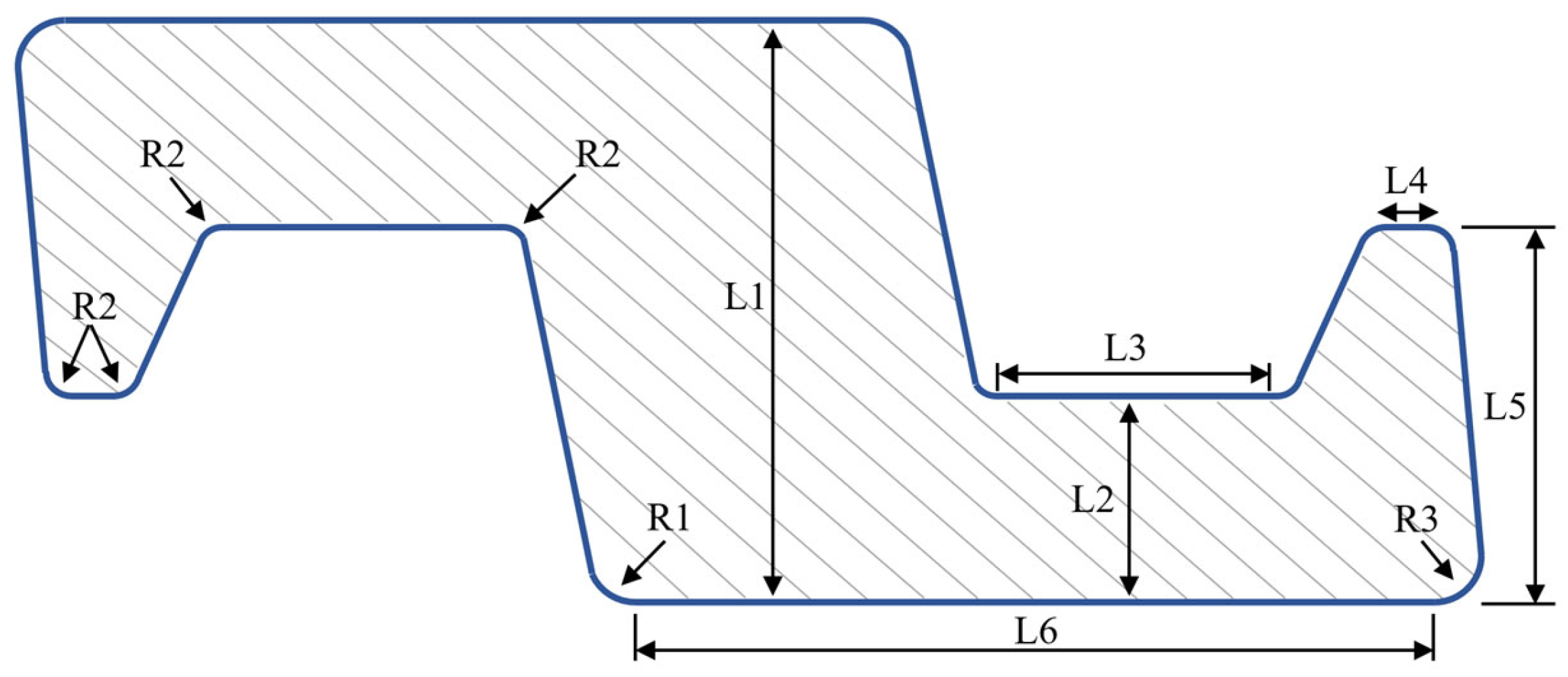
The 2.5-inch 8-layer unbonded flexible riser model proposed by Witz [2] is adopted as the research subject in this paper. A full-scale finite-element model is established in Abaqus (2022) software of 6.13 version using a layered modeling approach, where both the carcass layer and the pressure-armor layer are incorporated with detailed geometric configurations. Specifically, Figure 7 depicts the comprehensive cross-section geometry of the pressure-armor layer, the total length is approximately 14.5 mm with the other corresponding geometric properties presented in Table 1. In addition, the cross-sectional shape of the spiral strips in the tensile-armor layer is a regular rectangle, and the model in this paper is designed with two layers of tensile armor, where the inner and outer tensile-armor strata exhibit counter-directional lay angles. Meanwhile, technical specifications detailing constitutive and dimensional attributes for all individual layers within the unbonded flexible riser appear in Table 2.
The carcass layer, allowing oil and gas resources as well as seawater to flow freely in and out of this layer, is a self-locking, non-watertight structure formed by winding S-shaped spiral steel strips. It mainly bears the external liquid pressure [12]. In order to prevent the riser from crushing failure under pressure [34], oil and gas will have a direct impact on the inner sheath layer instead of the carcass layer. Therefore, the model can be simplified into a 7-layer model with the carcass layer removed for numerical simulation (as shown in Figure 8). The computational validity of the simplified model will be analyzed in the following sections. Meanwhile, the finite-element representation of the unbonded flexible riser must incorporate adequate length to effectively minimize boundary disturbance effects. Since the tensile-armor layer is the component that bears the primary mechanical properties in the riser, the length of the numerical model in this study is set to approximately twice the pitch length of the outer tensile-armor layer of the unbonded flexible riser, specifically 1.0 m.
To precisely document the stress distribution throughout the entire riser model and the specific deformation of each layer, while eliminating the impact of the hourglass issue on computational outcomes, an 8-node linear incompatible element (C3D8I) is employed for meshing the models of each layer. This element is more capable of managing plasticity, stress hardening, significant deformation, and substantial strain. The numerical model in this paper contains the pressure-armor layer structure considering the actual cross-sectional geometric shape, which involves a large number of geometric nonlinearity and contact nonlinearity problems. Therefore, in order to make the numerical calculation results of the finite-element software converge effectively, the explicit algorithm (ABAQUS) is adopted for solution in this paper.
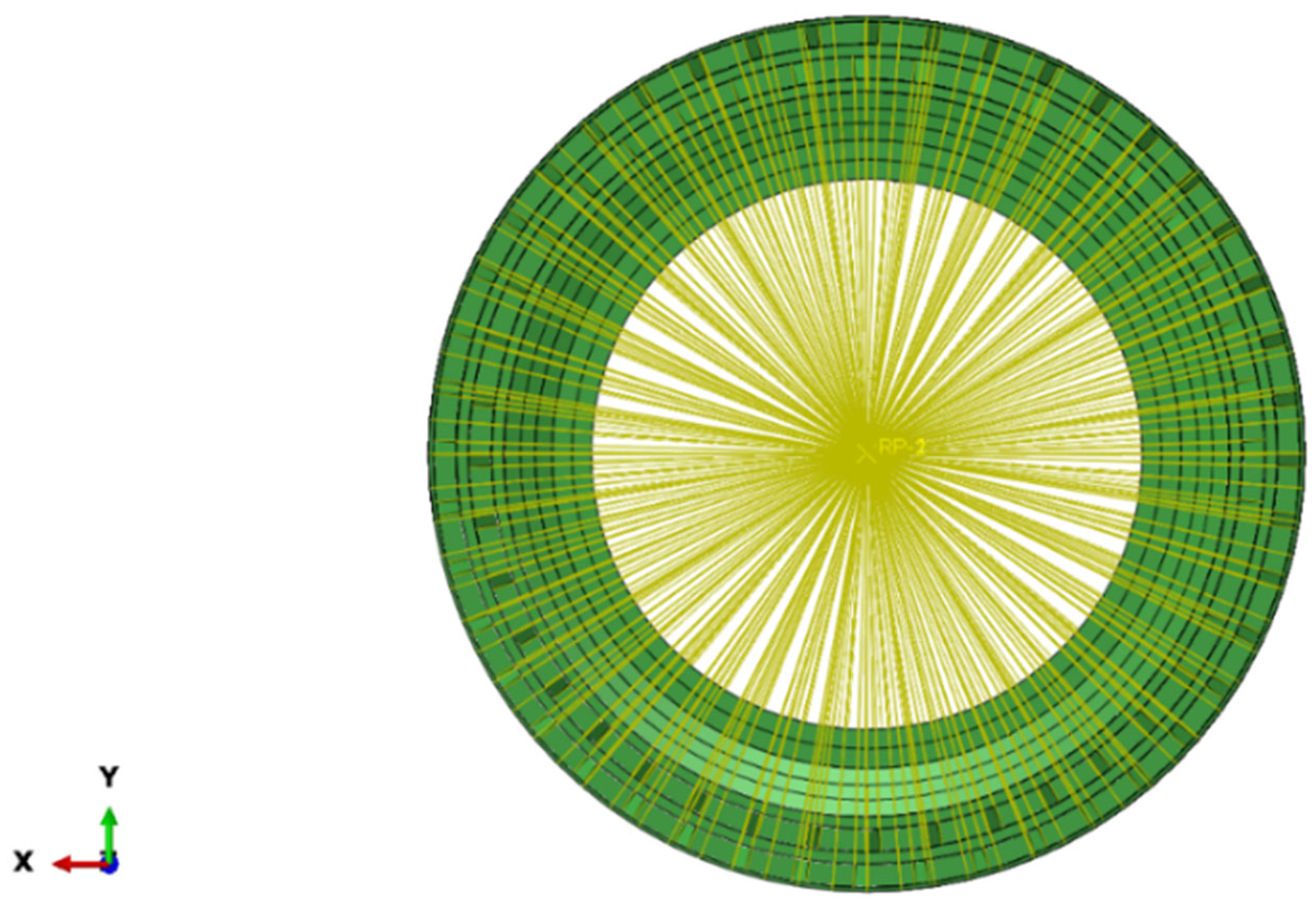
Two geometric reference points—RP-1 and RP-2—are positioned at both ends of the model’s central axis (see Figure 9) to aid in applying external loads to the riser’s numerical model and controlling the model’s boundary conditions with greater ease. Kinematic constraints are imposed across all degrees of freedom for individual layer components at prescribed end-section locations. Additionally, comprehensive constraints on the end faces are imposed on the two reference points: RP-1 is restricted in the torsional direction around the Z-axis, whereas RP-2 is fully constrained across all degrees of freedom (see Figure 10). For load application, the model’s axial tensile load is directly exerted on RP-1, and through applying a uniformly distributed radial pressure to the inner surface of the inner sheath, the internal pressure load is realized.
Given the presence of extensive nonlinear contacts both between layers and within layer structures in the numerical model, and in consideration of the model’s convergence, the explicit solver in ABAQUS is employed for computational analysis. Meanwhile, since inertial effects may affect the calculation results, it is necessary to regulate the kinetic energy during the computation process. In this study, the influence of inertial effects is mitigated through quasi-static loading. Specifically, the loading duration is extended, and a smooth step amplitude curve is adopted for loading, with the loading time set to 0.3 s.
As contact problems lack continuity-contact constraints and can only be introduced when surfaces are in contact with each other—the general contact algorithm [35] is utilized herein. This algorithm features a relatively simple definition and can automatically search for mutually contacting surfaces during computation. The normal contact property is set to hard contact, and the general function method is employed to enhance constraints, meaning separation occurs when the contact pressure between interfaces is no greater than zero. The tangential property is simulated using Coulomb friction.

3.2. Failure Criterion

3.2.1. Determination of Failure of Tensile-Armor Layer

When subjected to excessive axial tensile force, the tensile-armor layer experiences failure. Its yield strength is set as 650 MPa, with the ultimate strength specified as 1100 MPa. Using the simplified 7-layer riser model, various internal pressures are imposed, alongside a sufficiently high axial tensile load, to ensure the tensile-armor layer undergoes tensile failure. Failure of the tensile-armor component under tension is characterized by its axial load-elongation curve, stress contours, and strain contours. During the elastic phase, the stress distribution within the tensile-armor layer is relatively uniform; as the stress enters the plastic region, it gradually becomes concentrated. It is considered that once the stress in the tensile-armor layer reaches the plastic region, the layer stays in a compressed state until the element attains the ultimate stress and undergoes significant deformation.

3.2.2. Determination of Failure of Pressure–Tensile-Armor Layer

Internal pressure-induced bursting refers to the failure of the pressure-armor layer caused by excessive internal pressure. The pressure-armor layer is assigned a yield strength of 300 MPa and an ultimate strength of 600 MPa [36]. Employing the simplified 7-layer riser model, under varying axial tensile loads, a sufficiently high internal pressure is imposed to induce bursting failure in the pressure-armor layer. This bursting failure is characterized by the pressure-armor layer’s internal pressure-axial tensile deformation curve, stress contours, and strain contours.
In the linear stress phase of the pressure armor layer, the distribution of stress variations is relatively uniform. During the elastic phase, the stress distribution within the pressure-armor layer remains relatively even; as stress transitions into the plastic phase, it gradually accumulates in localized regions. Assumptions hold that once stress in the pressure-armor layer enters the plastic phase, the layer retains a compressed state—though to a far smaller degree—until the element attains ultimate stress and experiences significant deformation.

4. Discussion

The working conditions of unbonded flexible risers in the deep-sea environment are extremely complex. Their structures need to bear not only a single load but also the combined effects of multiple combined loads and internal and external pressures simultaneously. Thus, it is crucial to systematically study the mechanical responses of risers under combined loads. In the following paragraphs, the response characteristics and mechanical performance of risers under the action of internal pressure and axial tensile loads will be introduced in detail.

4.1. Model Verification

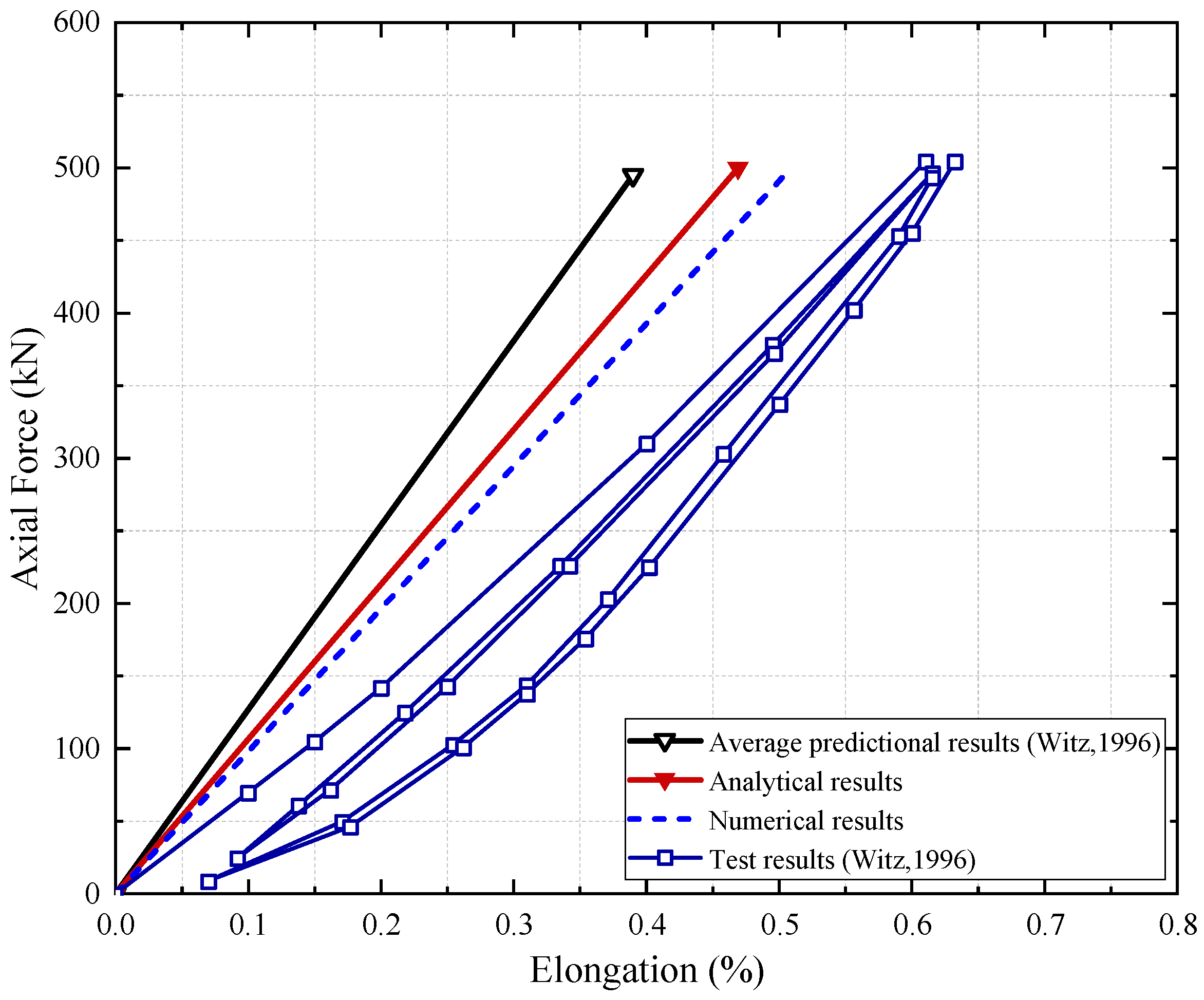
Building on Witz’s experiments, this study calculated the numerical and theoretical results of the unbonded flexible riser under tensile loading, with the outcomes presented in Figure 11. Moreover, Figure 11 also presents the average axial tensile stiffness that other scholars and organizations have predicted. The variations between the theoretical and numerical approaches are nearly linear, exhibiting a high degree of consistency. Meanwhile, with the average tensile stiffness derived from experimental methods as the benchmark, the numerical approach is more capable of predicting the axial tensile stiffness of the unbonded flexible pipe. Specifically, the relative deviations of the results obtained via the numerical and theoretical approaches (against the experimental data) are 8.07% and 14.81%, respectively.
Subsequent studies by various scholars have reported tensile stiffness values of unbonded flexible risers obtained using different methods. A comparison between these values and the finite-element model stiffness of 99.12 MN proposed in this study is presented in Table 3. The results show relatively small deviations, further demonstrating the validity of the model proposed in this study.
Building upon the verification of the validity of numerical and theoretical models when subjected to tensile loads, this paper compares the theoretical and numerical results of the axial elongation rate of the pressure-armor layer of the riser under the action of internal pressure (as shown in Figure 12). It is observed that the two match well in the linear stage. Consequently, under the action of internal pressure, the behavior of unbonded flexible risers can be effectively predicted through the numerical and theoretical methods put forward in this paper.
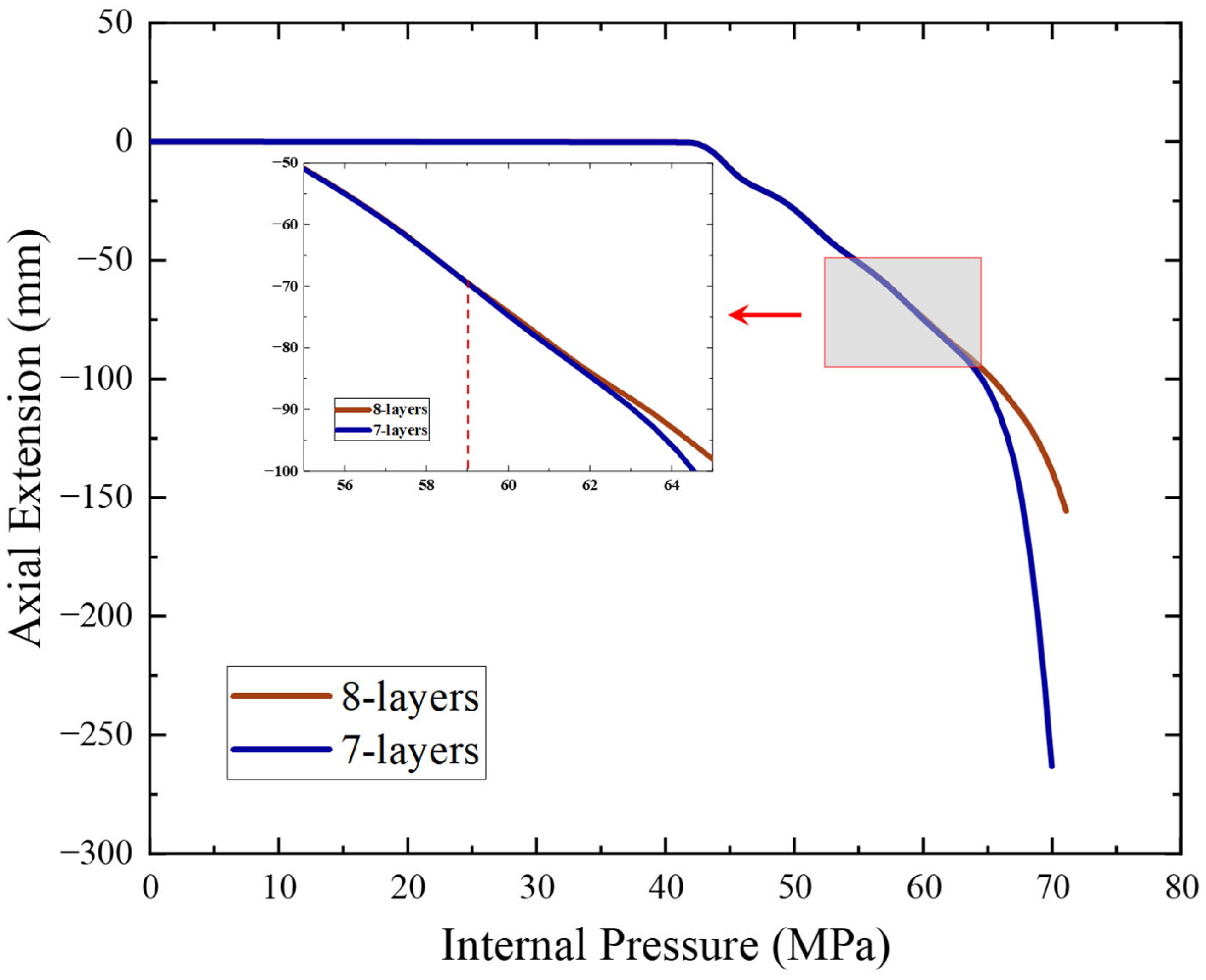
Furthermore, this study contrasts the internal pressure–axial elongation ratios of the full-layer model and the simplified numerical model. Analysis reveals that, prior to the yielding of the pressure-armor layer, the computational outcomes of the two models exhibit a near-linear trend (as shown in Figure 13) and show high consistency. As internal pressure continues to rise, the pressure-armor layer undergoes plastic deformation, with deviations between the two models emerging once the internal pressure reaches 59 MPa. The primary cause lies in the self-locking properties of the pressure-armor layer: its deformation induces corresponding deformation in the carcass layer, yet the theoretical model fails to account for the pressure-armor layer’s self-locking structure, thereby giving rise to discrepancies between the models. Overall, under internal pressure, the carcass layer’s deformation exerts minimal influence on the overall performance of the unbonded flexible riser, which confirms the validity of the 7-layer simplified numerical model.
Based on the above research, the 7-layer simplified model has significant computational efficiency advantages in the engineering linear design stage and the research focusing on the coupling failure of the sheath, and the accuracy meets the requirements. The 8-layer full model is a necessary choice for nonlinear limit analysis, fine failure mechanism research, and the simulation of lining behavior.

4.2. Failure Characteristic

4.2.1. Tensile Failure Characteristics

The ability of unbonded flexible risers to resist deformation under loads can be evaluated by their equivalent tensile, compressive, torsional, and bending stiffnesses. Axial tensile stiffness is a crucial mechanical property of unbonded flexible risers. When subjected to tensile loads, if the axial elongation of the flexible pipe is ε , the expression for the equivalent tensile stiffness K is as follows:
K = F / ε
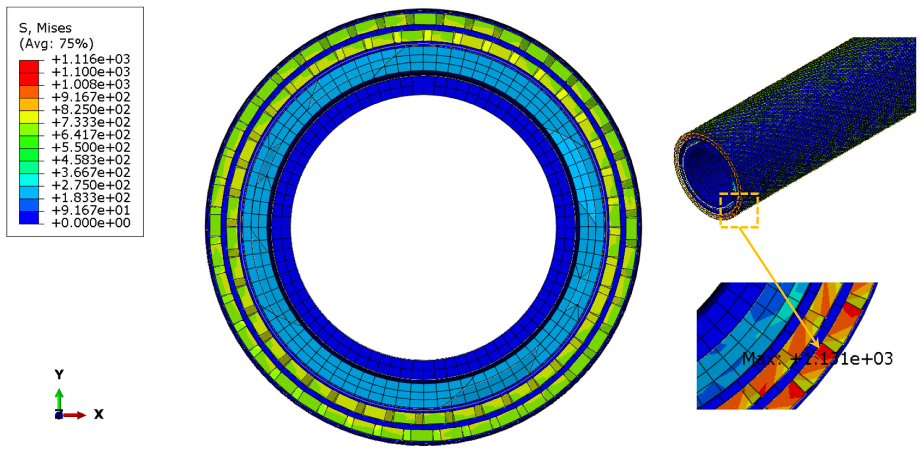
Figure 14 shows the cross-sectional stress distribution in the riser when the internal tensile-armor layer in Case 1 reaches the ultimate stress. Critically, the results reveal a highly non-uniform stress profile. As expected, the vast majority of the tensile load is carried by the inner and outer tensile-armor layers, which validates their primary function within the flexible pipe structure. More importantly, the identification of the stress concentration at the end of the tensile-armor wire is a key finding. This observation not only aligns with the established structural design principles of flexible risers but, crucially, confirms the predictive capability and scientific rationale of our simplified FE model. It demonstrates that the model successfully captures the critical failure mechanism, thereby justifying its use for this type of analysis and providing confidence in the subsequent results derived from it.
Figure 15a,b, respectively, present the Mises stress states of the internal and external tensile armors in the unbonded flexible riser in Case 1. Evidently, the stress in the internal tensile armor is greater than that in the external one, making the internal tensile armor more prone to failure. This may result in the initial instability of the inner layer [10]. This insight into the failure sequence is critical for prioritizing integrity monitoring and designing layered protection systems. Furthermore, when subjected to axial tension, the stress of the helical layer cannot change strictly and evenly along the riser’s axial direction. The stress distribution at the end of the helical layer is non-uniform, and especially more obvious in the external tensile armor, as shown in Figure 15b. In contrast, the stress distribution in the middle part of the external tensile armor is relatively uniform, with an average stress of approximately 550 MPa, while the average stress of some end elements is only about 360 MPa. This suggests that a portion of the load is transferred to adjacent layers or components at the terminus, creating stress concentrations elsewhere. Therefore, these results underscore the paramount importance of optimizing end-fitting design to mitigate stress concentrations.

4.2.2. Characteristics of Burst Failure

The primary component in unbonded flexible risers responsible for withstanding internal pressure is pressure-armor layer. With variations in other loads, the effect of internal pressure on the riser alters accordingly. Additionally, unlocking constitutes the most prevalent failure pattern of the pressure-armor layer.
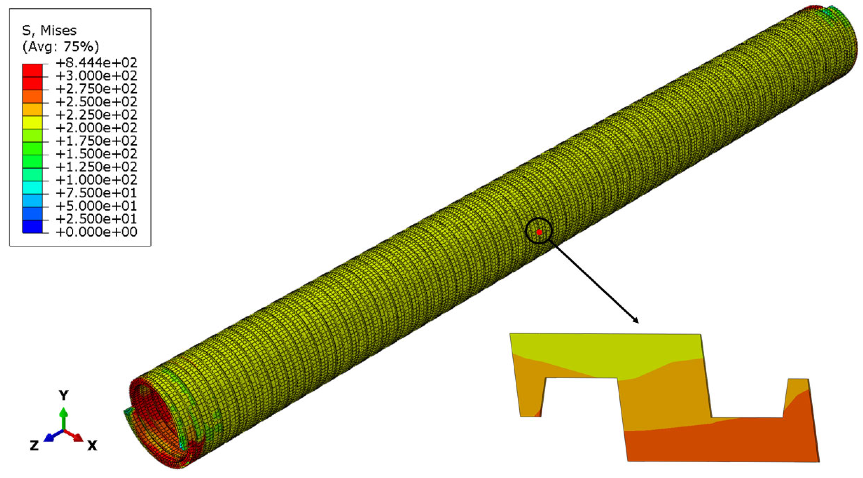
Figure 16 reveals substantially greater stress magnitudes along the pressure-armor stratum’s internal contour compared to its external surface. Moreover, the stress of the Z-shaped cross-section gradually decreases from bottom to top, which conforms to the general law of stress change along the cross-section thickness direction when the internal pressure acts. This stress distribution is critical, as it indicates that failure initiation is most likely to occur at the inner surface, guiding future inspection and failure analysis focus.
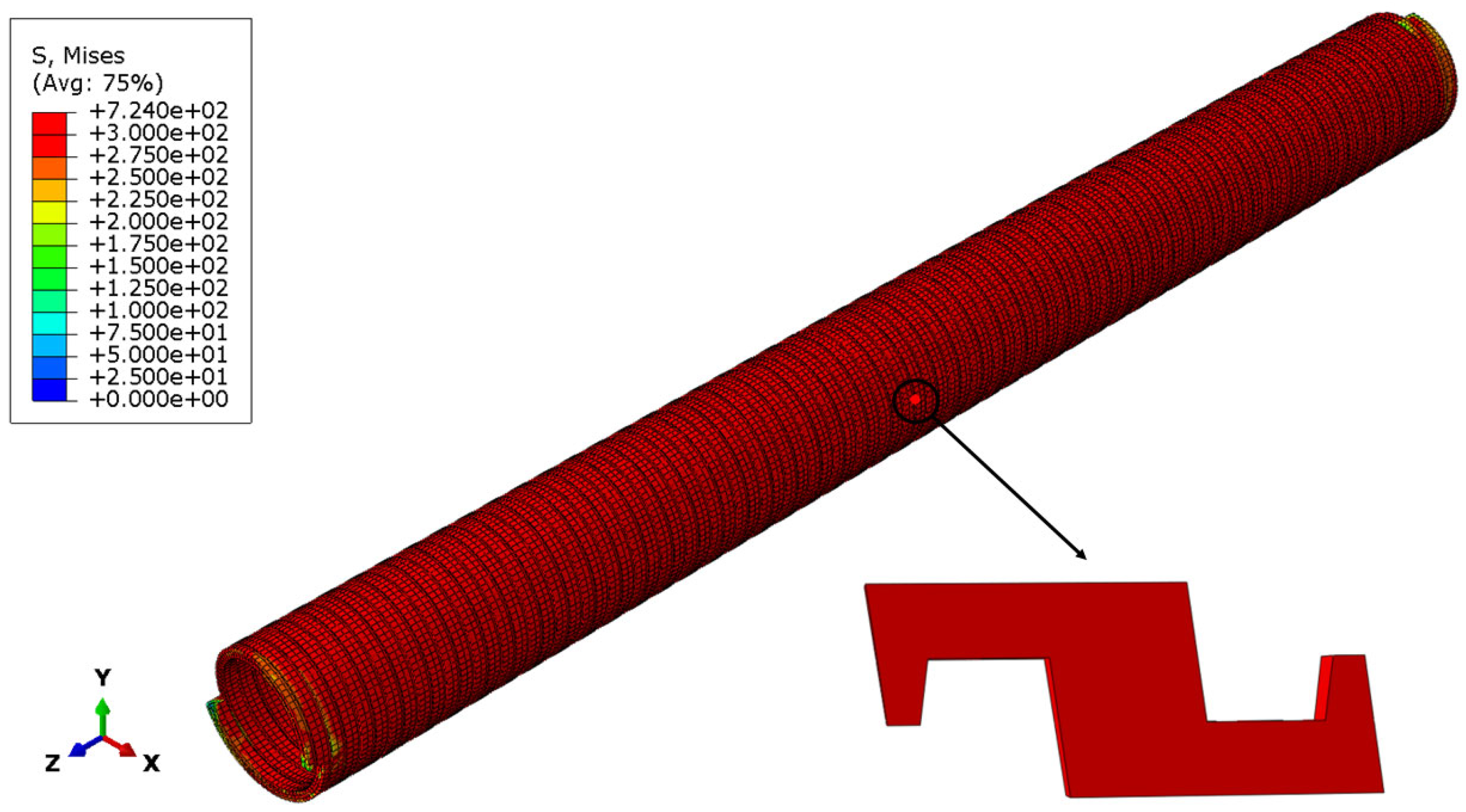
When the internal pressure reaches 42 MPa, the entire cross-section of the pressure-armor layer reaches the yield stress (as shown in Figure 17). The pressure-armor layer, with its self-locking structure, maintains a uniform axial deformation of the pipeline after basically reaching the yield stress, unlike the tensile-armor layer, which prevents stress concentration or large local deformations. This behavior is fundamentally different from a conventional ductile pipe and highlights the ingenious design of the Z-shaped profile: even in a plastic state, the interlocking mechanism prevents a catastrophic rupture by redistributing the load and maintaining structural integrity.
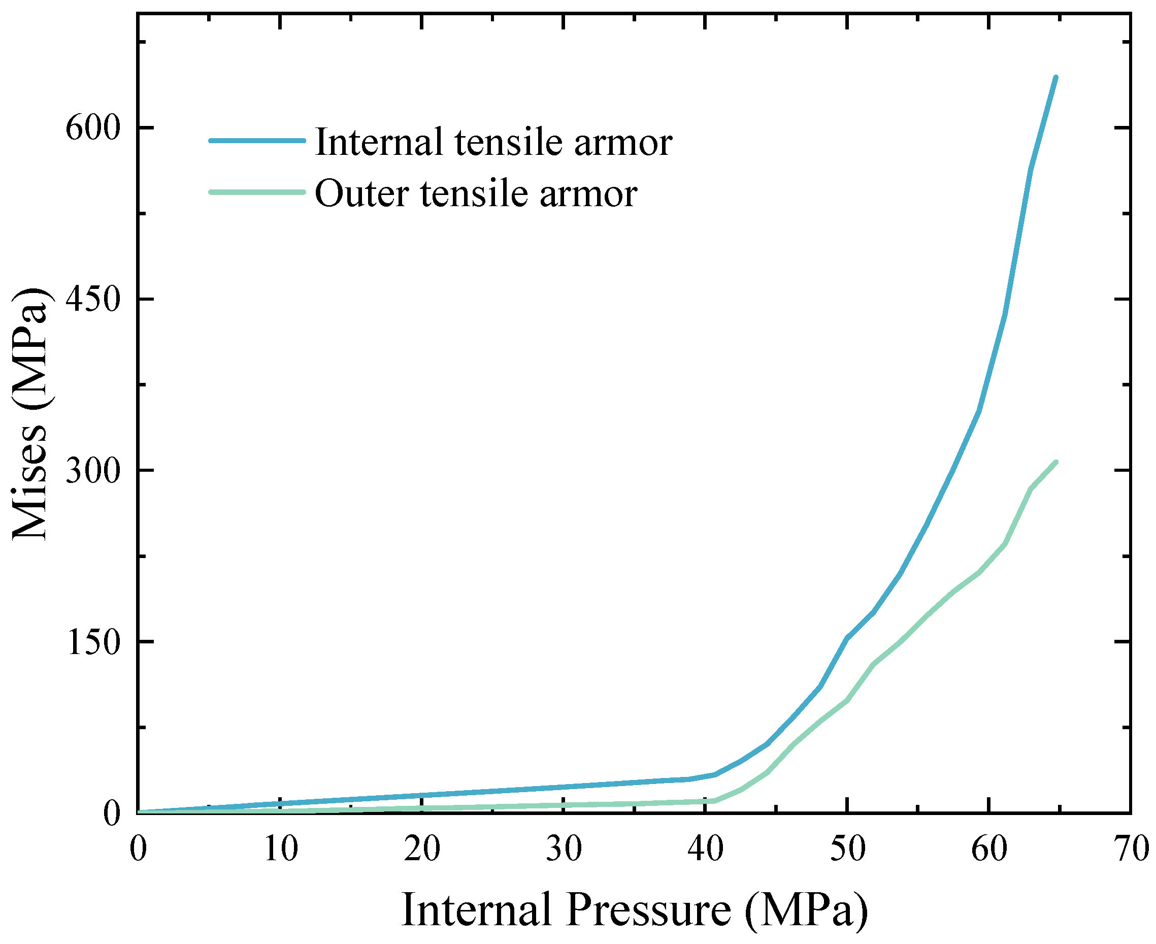
Figure 18 illustrates the evolution of von Mises stress in the inner and outer tensile-armor layers as a function of increasing internal pressure. When the pressure-armor layer yields (i.e., when the internal pressure reaches 42 MPa), the von Mises stresses of the tensile-armor layer increases sharply. This abrupt stress escalation signifies a fundamental shift in the load path: after the failure of the primary pressure-containing component (the pressure-armor layer), the tensile-armor layers are forced to absorb the additional hoop stress through their helical geometry. This verification further establishes that the tensile-armor layer assumes primary responsibility for resisting internal pressurization following failure of the pressure-armor layer. Furthermore, under sustained internal pressure loading, the internal tensile-armor layer continues to carry significantly greater loads than its external counterpart. This sudden load shift underscores the importance of considering this failure cascade in safety assessments. The system’s integrity post pressure-armor failure relies entirely on the residual capacity of the tensile armor, a scenario that must be accounted for in defining ultimate limit states and assessing overall system safety factors.

4.3. Parameter Analysis

4.3.1. Tensile Mechanical Response of Risers Under Combined Loads

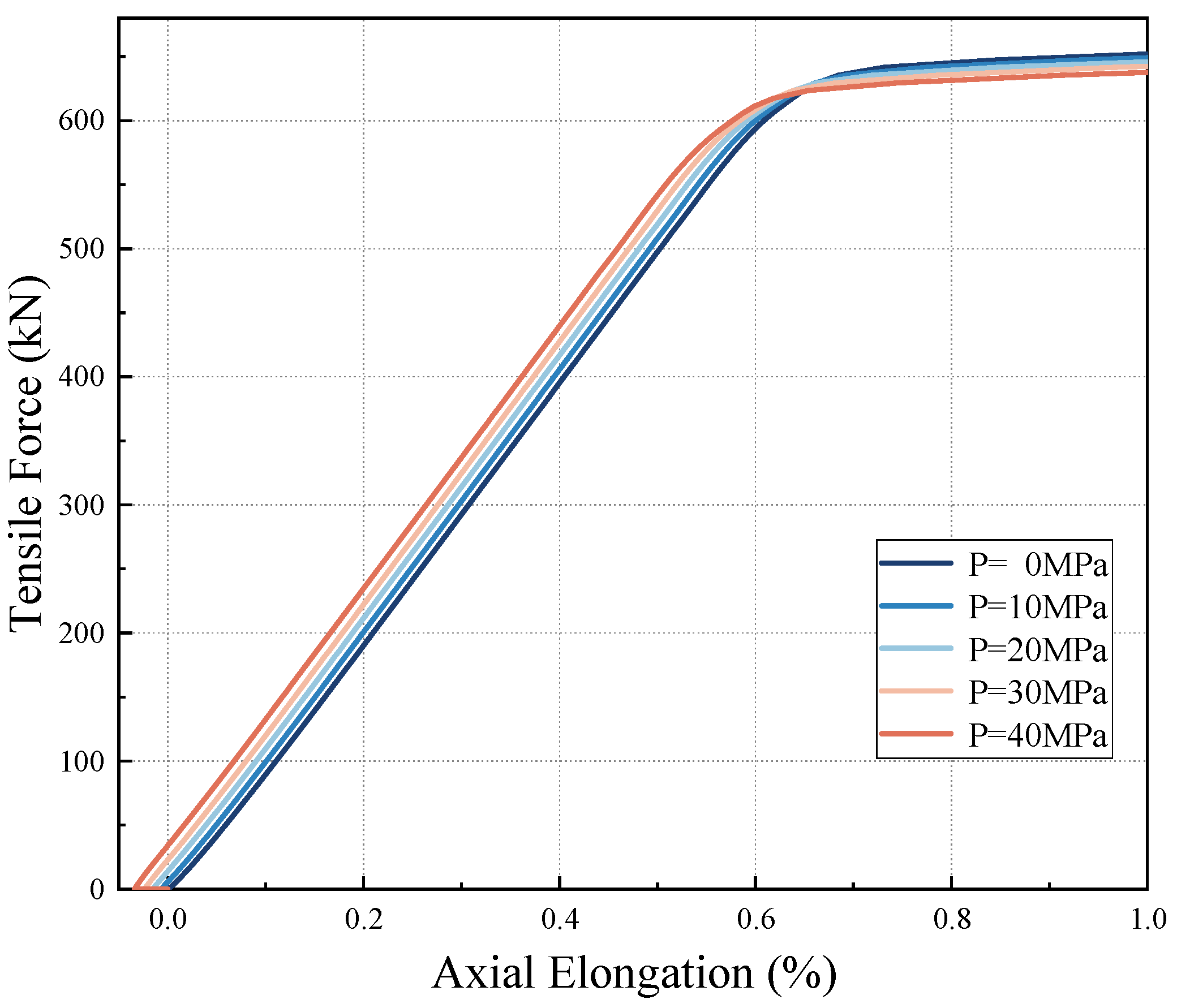
To study the influence of internal pressure on axial tensile failure, excessive axial tensile force is applied under different constant internal pressures to cause the tensile-armor layer to stretch and fail. The failure of the tensile-armor layer can be identified from the axial-load versus axial-elongation curve by locating the abrupt inflection point where the axial load changes significantly during loading. The working conditions are set as follows: the internal pressure ranges from 0 to 40 MPa, with an interval of 10 MPa; an axial tensile displacement load is applied.
Figure 19 presents the tensile characteristics of the riser under different initial internal pressure conditions. The results show that the application of initial internal pressure will make the riser experience axial shortening first. Then, when an axial tensile force is applied, risers under different internal pressures start to elongate linearly from different starting points. When the internal pressure is 40 MPa, the initial axial elongation rate is −0.034% until it returns to its original length. Notably, the pre-applied internal pressure has no significant impact on the slope of the axial elongation rate of the riser. This means that the initial internal pressure has almost no influence on the stiffness of the flexible pipe, and its stiffness remains 99.4 MN. The ability of the riser to resist deformation under axial loads has not changed. After reaching the ultimate stress, the riser fails. This observation—that pre-applied internal pressure has limited influence on the axial stiffness—is consistent with the findings of Sun et al. [20] and Tang et al. [21], who also reported that the axial tensile stiffness of unbonded flexible risers remains relatively stable under varying internal pressures.
Figure 20 presents the axial tensile forces which lead to the yielding of the inner tensile-armor layer under diverse initial internal pressure conditions. The analysis results show that with the increase in the initial internal pressure, the axial tensile force that the inner tensile-armor layer in the riser can endure exhibits a gradually decreasing trend, dropping from 593 kN when the internal pressure is 0 MPa to 574 kN when the internal pressure is 40 MPa, which decreases by 3.2%. Although the application of the initial internal pressure decreases the deformation amount of the riser to a certain degree, it also renders the riser more likely to experience axial failure simultaneously.

4.3.2. Pressure Mechanical Response of Risers Under Combined Loads

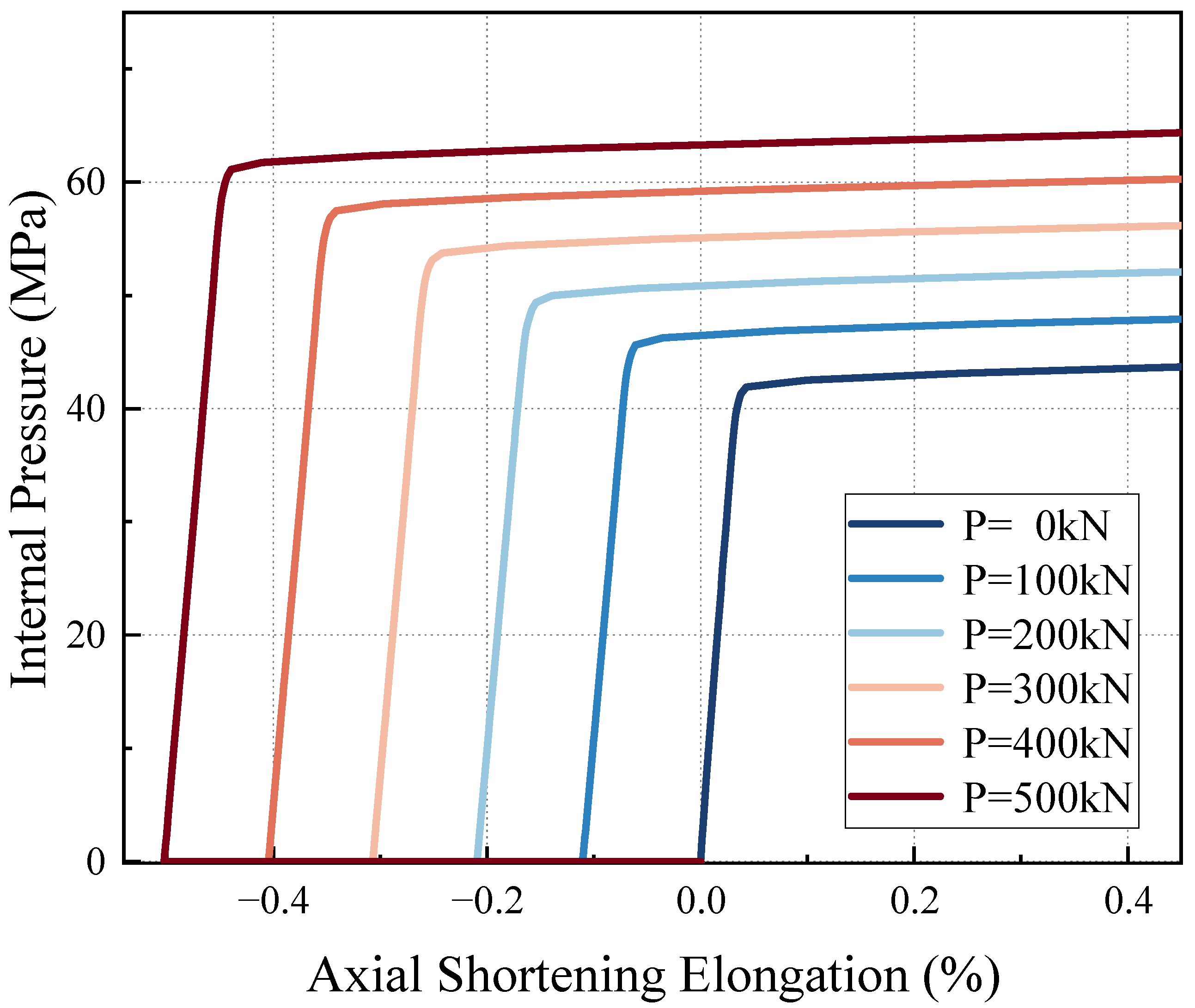
To study the influence of axial tensile load on internal burst failure, specific calculation working conditions were set as follows: the internal pressure was P = 100 MPa and the axial tensile load was T = 0–500 kN, with an interval of 100 kN. Meanwhile, the stress concentration caused by the end-boundary effect was neglected, and the stress distribution is consistent and relatively uniform during the internal pressure loading process.
Figure 21 indicates that, under the initial axial tensile force, the riser experiences axial elongation. Once the internal pressure begins to act, the riser then shows a trend of linear shortening. Evidently, the initially applied axial tensile force has no substantial impact on the slope of the axial shortening rate of the riser. Moreover, under different tensile forces, the change in the axial shortening rate of the unbonded flexible riser as the internal pressure rises remains the same.
Figure 22 extracts the stress at the intermediate position when the pressure-armor layer yields. The analysis results demonstrate that the maximum internal pressure that the pressure-armor layer can bear when it yields is significantly affected by the initial axial tensile force. Compared with the situation of no initial tensile force, the failure pressure increases by 35% when the tensile force is 500 kN. As the axial tensile force keeps increasing, the internal pressure value that the pressure-armor layer can endure rises accordingly. This, in turn, increases its failure threshold and exhibits a higher anti-failure ability. This significant enhancement reveals a previously underappreciated synergistic effect between tension and pressure in the failure regime. While recent studies have advanced our understanding of stiffness under combined loads [20,21], they did not extrapolate these findings to predict the ultimate failure boundary. Our work demonstrates that the initial axial tensile force pre-tensions and tightens the helical layers, improving their radial stiffness and resistance to the ovalization that precedes burst failure.
Current specifications generally adopt an “internal-pressure-dominant” curve for burst-limit verification, treating tension only as an additional membrane force that reduces the allowable value. The discovery that axial tension can enhance burst capacity by up to 35% challenges this paradigm. This suggests that for risers operating in high-tension environments (e.g., deep-water applications with large hang-off weights), the current design margins for burst failure may be overly conservative. Our proposed tension–pressure coupled failure boundary (as illustrated in Figure 22) provides a more accurate and potentially more efficient design envelope. By adopting this new boundary, engineers could optimize the cross-section design, potentially reducing material usage and overall weight without compromising safety, leading to significant cost savings in material and installation.
Figure 23 presents the stress contours of the pressure-armor layer at the time of riser failure under different initial axial tensile forces (in the x-y plane). It is observable that with the increase in internal pressure, the two ends of the pressure-armor layer are the first to reach the ultimate stress (600 MPa). As the initial axial tensile load rises, the two ends gradually reach the ultimate stress, and the area range reaching the ultimate stress also expands accordingly, ultimately leading to burst failure. Notably, when the initial tensile force is at 200 kN, the left end reaches the ultimate stress first. When it is at 400 kN, the right end first reaches the ultimate stress. Even at 500 kN, while the stress at the left end has not increased significantly, the right end has already burst and failed. This phenomenon implies that as the initial axial tensile force increases, the area that first reaches the ultimate stress shifts between the two ends of the armor layer, which is of great significance for the research on the riser failure mode. The migrating failure point can be rationalized by considering the boundary constraints imposed by the end fittings and the evolution of inter-layer contact pressure. Increasing axial tension redistributes the radial contact forces between the armor and the underlying carcass/pressure sheath, thereby shifting the position where local bending plus membrane stress is maximized. Simultaneously, the end fittings introduce highly localized radial restraint; the superposition of this fixed boundary effect with the moving “hoop-versus-bending” balance causes the hotspot to drift from one end to the other.
The observed migration of the failure initiation point is not merely an academic curiosity but has profound consequences for integrity management. In practical terms, this means that the location most susceptible to failure is not fixed but shifts with the load history. This insight critically informs risk-based inspection (RBI) strategies. Traditional inspection plans might focus on a presumed critical zone, but our findings indicate that inspections must account for the prevailing load conditions to correctly identify the current hotspot. For instance, if a riser is experiencing high tensile loads, inspection resources should be prioritized towards the end where the failure initiates under tension (e.g., the right end in this case). This allows for a more intelligent, condition-based allocation of inspection and maintenance resources, ultimately reducing downtime and life-cycle costs while improving safety by focusing on the area of highest actual risk.
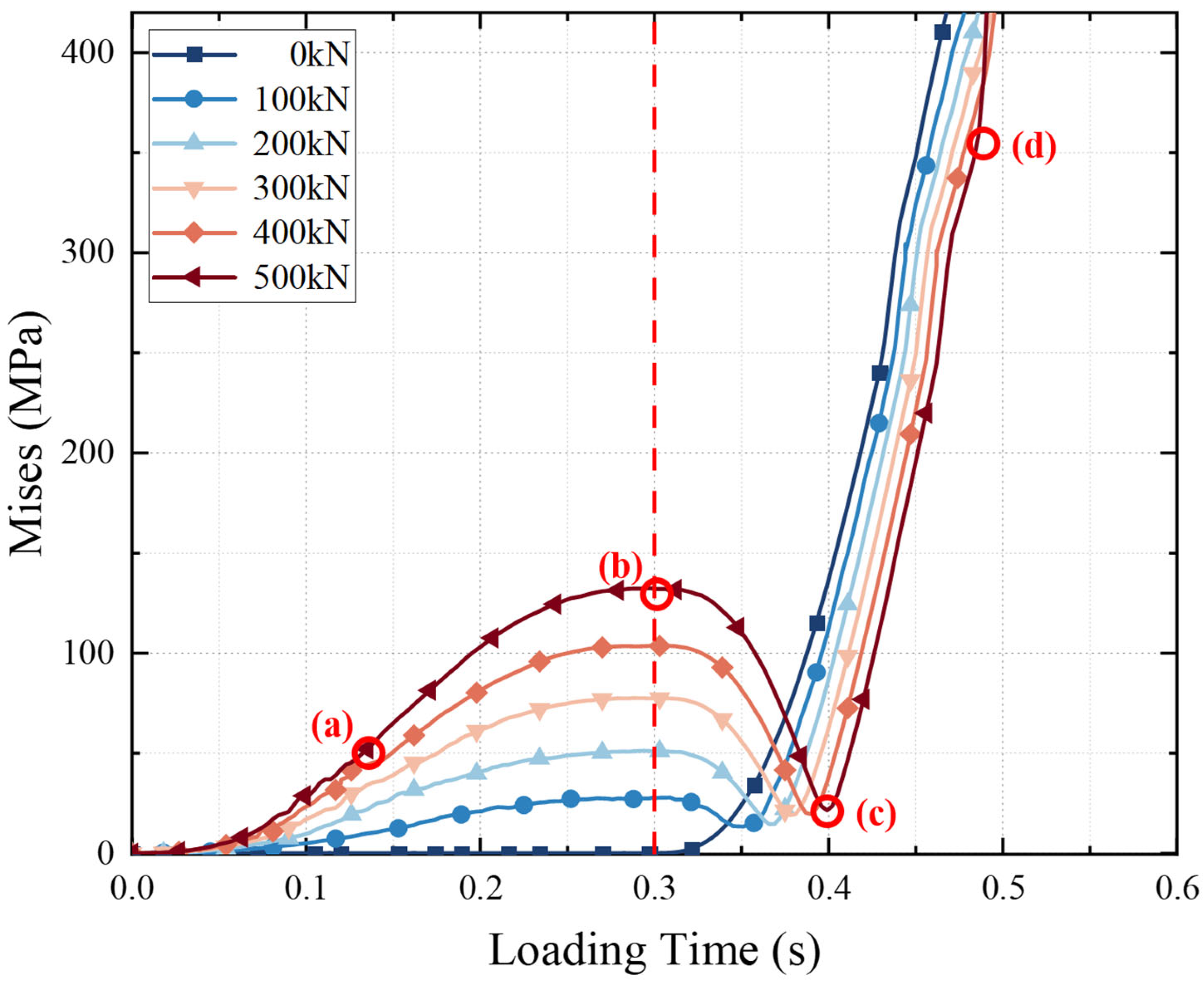
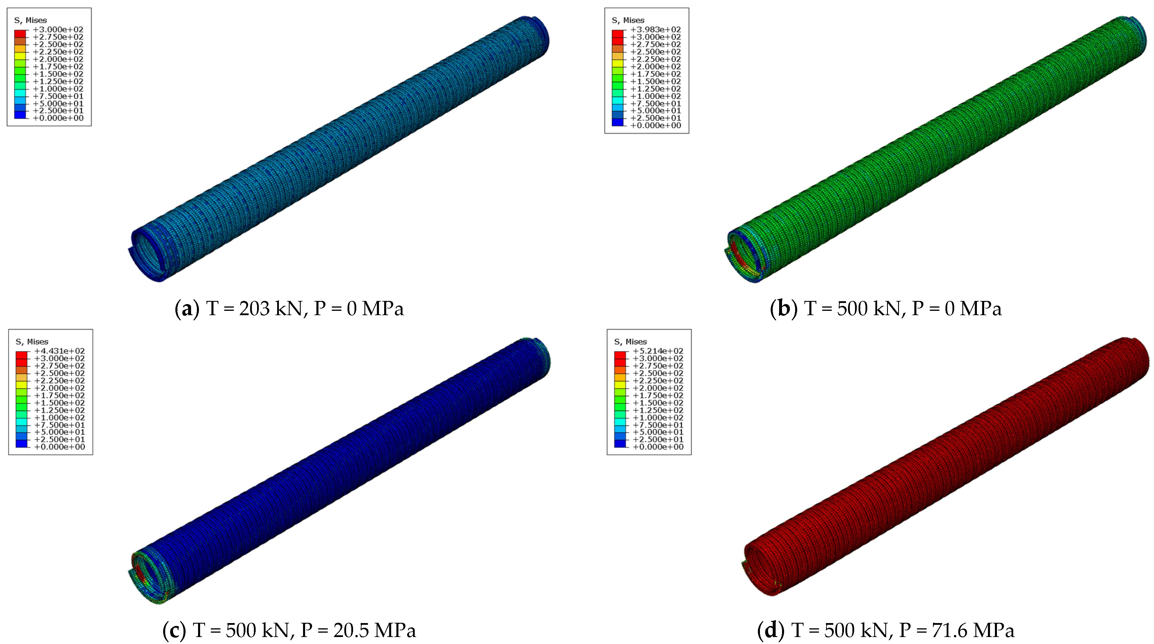
Figure 24 illustrates the variation in the von Mises at the same point of the pressure-armor layer with the analysis step under different initial tensile forces. Axial tensile forces are applied in the first 0.3 s, and internal pressure is applied after 0.3 s. Figure 25 shows the stress contours of the pressure-armor layer at four different special moments when the initial applied tensile force is 500 kN. It can be seen intuitively that the stress changes in the riser at different times and under different loads. In the initial stage of applying the axial tensile load, the stress increases nonlinearly until it reaches point b, as shown by (a) and (b) in Figure 24. After the internal pressure is applied (after 0.3 s), the increment of deformation due to the axial tensile force is gradually offset, and the stress also gradually decreases. Until a certain critical value (i.e., point (c) in Figure 24) is reached, that is, when the riser returns to its original length, the stress begins to show a linear increasing trend (d). The application of internal pressure (after 0.3 s) significantly affects the variation trend of the stress of the pressure-armor layer. Moreover, a larger initial axial tensile force causes the unbonded flexible riser to contract inward. At the same time, there is a larger initial axial elongation, which prevents the riser from expanding radially under the action of internal pressure, and also provides a larger adjustment space for the stress reduction. This phenomenon reasonably explains the variation presented in Figure 21; that is, the magnitude of the initial axial tensile force has an important influence on the failure characteristics of the pressure-armor layer. The larger the initial tensile force is, the larger the initial stress of the pressure layer under internal pressure is, and the internal pressure value when finally reaching the yield stress also increases accordingly.

5. Conclusions

In this paper, the mechanical properties of a 2.5-inch unbonded flexible riser under internal pressure and axial tensile load are studied numerically and verified analytically. This study fills a critical research gap by systematically investigating the coupled failure physics that previous works have overlooked. Constructed using ABAQUS, a 7-layer simplified model that excludes the carcass layer has been constructed. Then, the mixed failure characteristics of the unbonded flexible riser under initial internal pressure and axial tensile load as well as initial axial tensile load and internal pressure are studied. Beyond the fundamental mechanical insights, this study delivers tangible engineering value. The quantification of the tension-pressure coupling effect provides a scientific basis for moving beyond conservative design rules. Furthermore, the understanding of failure mechanism migration enables the development of more sophisticated and cost-effective integrity management protocols. By translating these findings into practice, the industry can achieve not only enhanced safety but also reduced capital and operational expenditures for deep-water developments. Principal research findings are consolidated below:
  • During tensile failure of unbonded flexible risers, both inner and outer tensile-armor layers assume primary load-bearing responsibility. Stress magnitudes within the internal tensile-armor layer exceed those sustained by the external counterpart. Moreover, when the riser is subjected to axial tension, the stress does not change strictly and evenly along its axial direction. This is especially obvious at the end.
  • Pre-applied internal pressure has no significant impact on the stiffness of unbonded flexible riser. Moreover, as the initial internal pressure increases from 0 MPa to 40 MPa, the axial tensile load capacity of the riser gradually diminishes. Although the deformation amount of the riser is reduced to a certain extent, it is more likely to experience axial failure. This is because the axial tensile load and the internal and external pressures will cause the contact pressure effect between the layers of the non-bonded flexible riser, so increasing the external pressure has a negative effect on the tensile strength of the composite riser.
  • Under combined loading, the pressure-armor layer carries most of the load and its Z-section stress grows from the inner edge to the outer edge. This layer first undergoes a stress drop, then re-loads until burst. After burst, the inner tensile-armor layer immediately takes over as the primary pressure-bearing component, its peak stress exceeding that of the outer layer and serving as a secondary barrier.
  • The initial axial tensile force magnitude significantly influences the failure characteristics of the pressure-armor layer. A higher initial tensile force endows it with a greater anti-burst ability; the failure pressure increases by 35% when the tensile force is 500 kN. This increase far exceeds the material’s own strain-hardening effect, primarily because the axial pre-compression suppresses radial ovalisation of the armor coil, thereby delaying the local buckling-yield coupling failure. Moreover, a larger initial axial tensile force results in a higher initial stress.

Author Contributions

Conceptualization, Q.L. and Y.L.; methodology, Q.L.; software, Y.L. and Q.W.; validation, J.H.; formal analysis, G.W.; investigation, M.L.; resources, Q.L. and M.L.; data curation, Y.L.; writing—original draft preparation, Q.L. and Y.L.; writing—review and editing, M.L.; visualization, Q.W.; supervision, Q.L.; project administration, G.W.; funding acquisition, Q.L. and M.L. All authors have read and agreed to the published version of the manuscript.

Funding

This paper was funded by the National Natural Science Foundation of China (Grant No. 12202236), the Natural Science Foundation of Jiangsu Province (Grant No. BK20220500), the China Postdoctoral Science Foundation (Grant No. 2025M772955), the Jiangsu Funding Program for Excellent Postdoctoral Talent (Grant No. 2022ZB560), and the Research Project of State Key Laboratory of Mechanical System and Vibration (Grant No. MSV202501).

Data Availability Statement

The original contributions presented in this study are included in the article. Further inquiries can be directed to the corresponding authors.

Conflicts of Interest

The authors declare no conflicts of interest.

References

  1. Liu, Q.S.; Xue, H.X.; Tang, W.Y.; Yuan, Y. Theoretical and numerical methods to predict the behavior of unbonded flexible riser with composite armor layers subjected to axial tension. Ocean Eng. 2020, 199, 107038. [Google Scholar] [CrossRef]
  2. Tchalala, M.R.; El-Demellawi, J.K.; Kalakonda, P.; Chaieb, S. High thermally stable hybrid materials based on amorphous porous silicon nanoparticles and imidazolium-based ionic liquids: Structural and chemical analysis. Mater. Today Proc. 2021, 39, 1132–1140. [Google Scholar] [CrossRef]
  3. Kalakonda, P.; Thudumu, S.; Mynepally, S.L.; Mandal, P.; Banne, S.; Kalakonda, P.B.; Podili, B.B. Engineering micro/nano-fibrous scaffolds with silver coating for tailored wound repair applications. J. Nanoparticle Res. 2023, 25, 254. [Google Scholar] [CrossRef]
  4. Dabbeta, N.K.; Kante, M.; Konda, R.; Devarala, A.; Kalakonda, P.B.; Khanam, S.J.; Savu, R.N.; Banovath, M.; Siddey, L.S.R.; Bommaji, V.N.; et al. ECO-inspired Cu-Zn bimetallic nanoparticles for Enhanced Water Purification Technologies. Mater. Chem. Phys. Sustain. Energy 2025, 2, 100013. [Google Scholar] [CrossRef]
  5. Hasan, I.; Bassi, A.; Kalakonda, P. CuO surface functionalized β-cyclodextrin grafted PMMA hybrid nanocomposite for advance oxidative mineralization of methyl orange. Surf. Interfaces 2025, 56, 105456. [Google Scholar] [CrossRef]
  6. Witz, J.A. A case study in the cross-section analysis of flexible risers. Mar. Struct. 1996, 9, 885–904. [Google Scholar] [CrossRef]
  7. Yue, Q.J.; Lu, Q.Z.; Yan, J.; Zheng, J.; Palmer, A. Tension behavior prediction of flexible pipelines in shallow water. Ocean Eng. 2013, 58, 201–207. [Google Scholar] [CrossRef]
  8. Vargas-Londoño, T.; de Sousa, J.R.M.; Magluta, C.; Rotiman, N. A theoretical and experimental analysis of the bending behavior of unbonded flexible pipes. In Proceedings of the ASME 2014 33rd International Conference on Ocean, Offshore and Arctic Engineering, San Francisco, CA, USA, 8–13 June 2014. OMAE2014-24247. [Google Scholar]
  9. Zhou, C.; Ye, N.; Sævik, S. Effect of anti-wear tape on behavior of flexible risers. In Proceedings of the ASME 2014 33rd International Conference on Ocean, Offshore and Arctic Engineering, San Francisco, CA, USA, 8–13 June 2014. OMAE2014-24261. [Google Scholar]
  10. Shao, W.Z.; Lin, Y.; Yan, J.H. Modeling the reeling process of offshore pipelines: A theoretical framework based on updated Voce-Chaboche model. Ocean Eng. 2025, 332, 121383. [Google Scholar] [CrossRef]
  11. Kebadze, E. Theoretical Modelling of Unbonded Flexible Pipe Cross-Sections. Doctoral Thesis, South Bank University, London, UK, 2000. [Google Scholar]
  12. Dong, L.L. Theoretical Calculation of Cross-Sectional Properties and Fatigue Analysis of Unbonded Flexible Risers in BSR Region. Doctoral Thesis, Dalian University of Technology, Dalian, China, 2013. [Google Scholar]
  13. Bahtui, A. Development of a Constitutive Model to Simulate Unbonded Flexible Riser Pipe Elements. Doctoral Thesis, Brunel University, London, UK, 2008. [Google Scholar]
  14. Ren, S.F.; Tang, W.Y.; Kang, Z.; Geng, H. Numerical study on the axial-torsional response of an unbonded flexible riser with damaged tensile armor wires. Appl. Ocean Res. 2020, 97, 102045. [Google Scholar] [CrossRef]
  15. Cornacchia, F.; Liu, T.; Bai, Y.; Fantuzzi, N. Tensile strength of the unbonded flexible pipes. Compos. Struct. 2019, 218, 142–151. [Google Scholar] [CrossRef]
  16. De Sousa, J.R.M.; Campello, G.C.; Kwietniewski, C.E.F.; Ellwanger, G.B.; Strohaecker, T.R. Structural response of a flexible pipe with damaged tensile armor wires under pure tension. Mar. Struct. 2014, 39, 1–38. [Google Scholar] [CrossRef]
  17. Liu, Q.S.; Xue, H.X.; Tang, W.Y. Behavior of unbonded flexible riser with composite armor layers under coupling loads. Ocean Eng. 2021, 229, 109907. [Google Scholar] [CrossRef]
  18. Jiang, H.; Yang, H.Z. Mechanical analysis of deep water unbonded flexible riser under combined loads. China Ocean Eng. 2014, 32, 93–99. [Google Scholar]
  19. Wang, B.D.; Zhang, H.; Liu, X.B.; Xu, L.X.; Fu, Y. Analysis of the Mechanical Behaviors of Fiber Reinforced Unbonded Flexible Pipe Under Combined Load. In Proceedings of the 13th International Pipeline Conference, Calgary, AB, Canada, 28–30 September 2020. IPC2020-9346. [Google Scholar]
  20. Sun, H.B.; Wang, Y.Y.; Jia, L.S.; Lin, Z.Q.; Yu, H. Theoretical and numerical methods for predicting the structural stiffness of unbonded flexible riser for deep-sea mining under axial tension and internal pressure. Ocean Eng. 2024, 310, 118672. [Google Scholar] [CrossRef]
  21. Tang, L.P.; He, W.; Zhu, X.H.; Zhou, Y.L. Mechanical analysis of un-bonded flexible pipe tensile armor under combined loads. Int. J. Press. Vessel. Pip. 2019, 171, 217–223. [Google Scholar] [CrossRef]
  22. Yoo, D.H.; Jang, B.S.; Yim, K.H. Nonlinear finite element analysis of failure modes and ultimate strength of flexible pipes. Mar. Struct. 2017, 54, 50–72. [Google Scholar] [CrossRef]
  23. Berge, S.; Wang, T.; Langhelle, N. Surface characterization and fatigue strength of corroded armor wire. In Proceedings of the 33rd International Conference on Offshore Mechanics and Arctic Engineering, San Francisco, CA, USA, 8–13 June 2014. OMAE2014-24140. [Google Scholar]
  24. Antoine, F.H. Prevention and monitoring of fatigue-corrosion of flexible risers’ steel reinforcements. In Proceedings of the 21st International Conference on Offshore Mechanics and Arctic Engineering, San Diego, CA, USA, 10–15 June 2007. OMAE2007-29186. [Google Scholar]
  25. Ebrahimi, A.; Kenny, S.; Hussein, A. Finite Element Investigation on the Tensile Armor Wire Response of Flexible Pipe for Axisymmetric Loading Conditions Using an Implicit Solver. J. Offshore Mech. Arct. Eng. 2018, 140, 041402. [Google Scholar] [CrossRef]
  26. Zhu, X.-K.; Leis, B.N. Theoretical and numerical predictions of burst pressure of pipelines. J. Press. Vessel Technol. 2007, 129, 644–652. [Google Scholar] [CrossRef]
  27. Kamaya, M.; Suzuki, T.; Meshii, T. Failure pressure of straight pipe with wall thinning under internal pressure. Int. J. Press. Vessel. Pip. 2008, 85, 628–634. [Google Scholar] [CrossRef]
  28. Neto, A.; Martins, C.; Pesce, C.; Meirelles, C.; Malta, E.; Neto, T.; Godinho, C. Prediction of burst in flexible pipes. J. Offshore Mech. Arct. Eng. 2013, 135, 011401. [Google Scholar] [CrossRef]
  29. Zeng, D.Z.; Wang, X.; Ming, K.J.; Yu, C.X.; Zhang, Y.H.; Yu, Z.M.; Yan, J.; Li, F.G. Analysis and optimization design of internal pressure resistance of flexible composite pipe. Int. J. Press. Vessel. Pip. 2024, 210, 105271. [Google Scholar] [CrossRef]
  30. Liu, X.Y.; Qu, Z.Y.; Liu, Y.; He, J.W.; Si, G.J.; Wang, S.C.; Liu, Q.S. Numerical Simulation of Burst Failure in 2.5-Inch Unbonded Flexible Riser Pressure Armor Layers. Metals 2024, 14, 762. [Google Scholar] [CrossRef]
  31. Wei, R.; Li, X.; Vaz, M.A.; Custódio, A.B. Finite Element Modelling of Pressure Armor Unlocking Failure in Unbonded Flexible Risers. J. Mar. Sci. Eng. 2025, 13, 411. [Google Scholar] [CrossRef]
  32. Ren, S.F. Mechanical Properties and Typical Failure Characteristics of Unbonded Flexible Riser Cross-Sections. Doctoral Thesis, Shanghai Jiao Tong University, Shanghai, China, 2015. [Google Scholar]
  33. Zhang, X.J.; Chang, Z.Y. Advance of research of unbonded flexible risers. In Proceedings of the International Conference on Applied Mechanics and Materials, Sanya, China, 15–16 November 2014. ICAMM1015–1019. [Google Scholar]
  34. Grytå, G. Fatigue of Flexible Riser in Bend Stiffener Area. Master’s Thesis, Norwegian University of Science and Technology, Trondheim, Norway, 2011. [Google Scholar]
  35. Zhang, M.M.; Chen, X.Q.; Fu, S.X.; Guo, Y.; Ma, L. Theoretical and numerical analysis of bending behavior of unbonded flexible risers. Mar. Struct. 2015, 44, 311–325. [Google Scholar] [CrossRef]
  36. Cuamatzi-Melendez, R.; Castillo-Hernández, O.; Vázquez-Hernández, A.; Albiter5, A.; Váz, M. Finite element modeling of burst failure in unbonded flexible risers. Eng. Struct. 2015, 87, 58–69. [Google Scholar] [CrossRef]
  37. Lei, Q.L.; Chen, C.Y.; Zhu, X.H. Tensile failure behavior of unbonded flexible riser with damaged tensile armor wires. Ocean Eng. 2023, 267, 113112. [Google Scholar] [CrossRef]
  38. De Sousa, J.R.M.; Viero, P.F.; Magluta, C.; Roitman, N. An Experimental and Numerical Study on the Axial Compression Response of Flexible Pipes. J. Offshore Mech. Arct. Eng. 2012, 134, 031703. [Google Scholar] [CrossRef]
  39. Ramos, R., Jr.; Martins, C.d.A.; Pesce, C.P. A case study on the axial-torsional behavior of flexible risers. In Proceedings of the ASME 27th International Conference on Offshore Mechanics and Arctic Engineering, Estoril, Portugal, 15–20 June 2008. OMAE2008-57514. [Google Scholar]
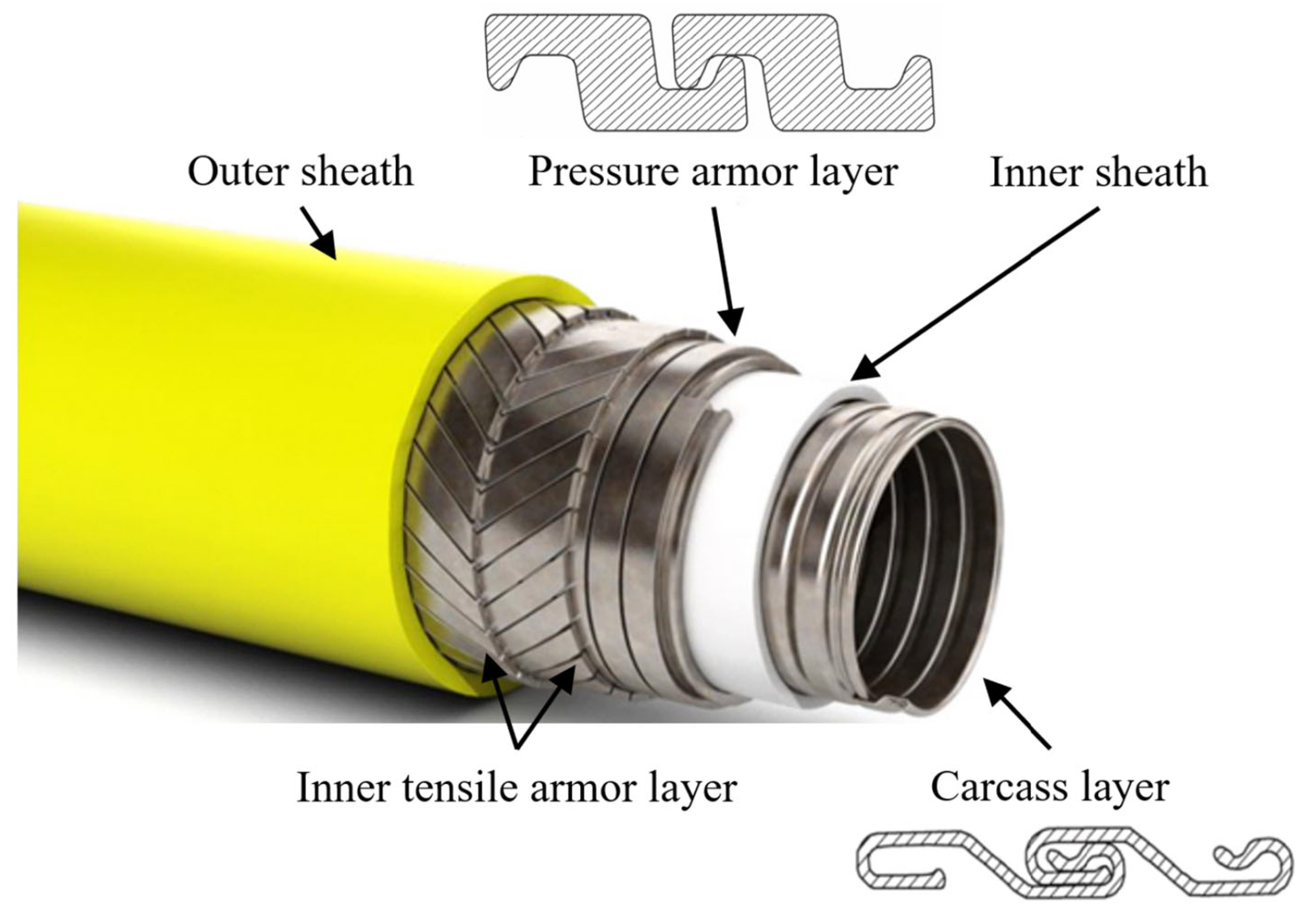
Figure 1. Unbonded flexible riser of rough bore type.
Jmse 13 01866 g001
Figure 2. A typical sketch of a deep-water unbonded flexible riser. (a) Z type; (b) C type; (c) T type—1; (d) T type—2; (e) K type; (f) X type.
Jmse 13 01866 g002
Figure 3. Diagram of the cylindrical layer under axisymmetric loads.
Jmse 13 01866 g003
Figure 4. Loading condition of helical layer.
Jmse 13 01866 g004
Figure 5. Profiles of helical layer.
Jmse 13 01866 g005
Figure 6. Helical element with axial and radial strains.
Jmse 13 01866 g006
Figure 7. Cross-section properties of pressure-armor layer.
Jmse 13 01866 g007
Figure 8. Cross-section of an unbonded flexible riser FE model.
Jmse 13 01866 g008
Figure 9. Reference points of finite-element model of unbonded flexible riser.
Jmse 13 01866 g009
Figure 10. Kinematic constraints applied to the riser ends at RP-2.
Jmse 13 01866 g010
Figure 11. Axial force-elongation curves of different techniques [6].
Jmse 13 01866 g011
Figure 12. Relationship between internal pressure and axial shift.
Jmse 13 01866 g012
Figure 13. Comparison of internal pressure–axial extension elongation curves by full-layer model and simplified numerical model.
Jmse 13 01866 g013
Figure 14. Map of von Mises stresses on the cross-section of simplified FE model.
Jmse 13 01866 g014
Figure 15. Distribution of von Mises stress in the tensile-armor layer under tensile load. (a) The distribution of von Mises stress in the internal tensile armor; (b) the distribution of von Mises stress in the external tensile armor.
Jmse 13 01866 g015
Figure 16. Contours of the pressure-armor layer.
Jmse 13 01866 g016
Figure 17. Contours of the pressure-armor layer at yield stress.
Jmse 13 01866 g017
Figure 18. von Mises–internal pressure relation diagram of tensile-armor layer.
Jmse 13 01866 g018
Figure 19. Tensile force versus axial relative elongation of the flexible pipe in different circumstances.
Jmse 13 01866 g019
Figure 20. The maximum tensile force that the internal tensile armor can withstand under different internal pressure.
Jmse 13 01866 g020
Figure 21. Internal pressure versus axial shortening elongation of the flexible pipe in different circumstances.
Jmse 13 01866 g021
Figure 22. Internal pressure versus axial force at yield.
Jmse 13 01866 g022
Figure 23. Distribution of von Mises stress in the pressure-armor layer. (a) T = 100 kN; (b) T = 200 kN; (c) T = 300 kN; (d) T = 400 kN; (e) T = 500 kN.
Jmse 13 01866 g023
Figure 24. Resistance to pressure at the same point in the armor.
Jmse 13 01866 g024
Figure 25. Distribution of von Mises stress in the pressure-armor layer. ((a) T = 203 kN, P = 0 MPa; (b) T = 500 kN, P = 0 MPa; (c) T = 500 kN, P = 20.5 MPa; (d) T = 500 kN, P = 71.6 MPa).
Jmse 13 01866 g025
Table 1. Geometric parameters of pressure-armor layer.
ParameterValueParameterValueParameterValue
L16.2 mmL40.5 mmR11.0 mm
L22.2 mmL54.0 mmR20.5 mm
L33.0 mmL68.5 mmR31.0 mm
Table 2. Geometric and material parameters of an 8-layer unbonded flexible riser [6].
Layer NumberLayer TypeSection Size (mm2)Inner Radius (mm)Outer Radius (mm)Number of TendonsLaying Angle (°)Material
1Carcass layer28 × 0.731.6035.101−87.5AISI 304
2Pressure sheath-35.1040.00--Nylon 12
3Pressure
armor layer
9.25 × 0.640.0546.252−85.5FI-15
4Anti-friction tape-46.2547.75--Nylon 11
5Inner tensile armor6 × 347.7550.7540−35.0FI-41
6Anti-friction tape-50.7552.25--Nylon 11
7Outer tensile armor6 × 352.2555.254435.0FI-41
8Fabric tape-55.2555.75---
Table 3. Axial tensile stiffness values obtained from different organizations and scholars.
Axial Tensile StiffnessRelative DeviationReferences
86.8 MN12.4%Numerical (Lei et al., 2023) [37]
108.7 MN9.6%Numerical (Tang et al., 2019) [21]
105.1 MN6%Experiment (de Sousa et al., 2012) [38]
127 MN28.1%Analytical (Ramos, 2008) [39]
Disclaimer/Publisher’s Note: The statements, opinions and data contained in all publications are solely those of the individual author(s) and contributor(s) and not of MDPI and/or the editor(s). MDPI and/or the editor(s) disclaim responsibility for any injury to people or property resulting from any ideas, methods, instructions or products referred to in the content.