Article

Calculation and Analysis of Rolling Hydrodynamic Coefficients of Free-Flooding Ship Based on CFD

1
School of Ocean and Civil Engineering, Shanghai Jiao Tong University, Shanghai 200240, China
2
Marine Design and Research Institute of China, Shanghai 200011, China
3
Shanghai Rules and Research Institute, China Classification Society, Shanghai 200135, China
4
Ships and Offshore Installations Structural Safety Laboratory, China Classification Society, Shanghai 200135, China
*
Author to whom correspondence should be addressed.
J. Mar. Sci. Eng. 2025, 13(10), 1857; https://doi.org/10.3390/jmse13101857
Submission received: 18 August 2025 / Revised: 11 September 2025 / Accepted: 12 September 2025 / Published: 25 September 2025
(This article belongs to the Special Issue Advancements in Marine Hydrodynamics and Structural Optimization)

Abstract

As free-flooding ships are a type of vessel with openings on their hull surfaces, accurately calculating and analyzing their roll hydrodynamic coefficients is of great significance for ship motion prediction. Based on the STAR CCM+ platform that employs the computational fluid dynamics (CFD) method, this paper first conducts numerical simulations of the forced roll motion of a damaged DTMB-5415 ship model. The applicability of this method to side-opening ship types is verified by comparing with experimental results. Subsequently, this numerical method is applied to simulate the forced roll of a free-flooding aquaculture ship under different working conditions, and the roll hydrodynamic coefficients of its hull and internal compartments are calculated and analyzed. The roll hydrodynamic coefficients of the intact ship and the free-flooding ship are compared. The results indicate the characteristics of roll hydrodynamic coefficients of free-flooding ships, and this research will facilitate the prediction of roll motion for this ship type.

1. Introduction

The motion of a ship in waves involves six degrees of freedom, among which roll motion is the most critical and complex. Most ship capsizing accidents in history have been related to excessive roll angles. However, compared with motions in other degrees of freedom, the viscous effects in roll motion are the most significant. For example, in conventional ships, flow separation occurs at the bilge during rolling, accompanied by the generation and shedding of vortices. In addition, large roll angles also introduce nonlinearity in the motion. These factors make the calculation effect of roll hydrodynamic coefficients based on potential flow methods such as slice theory not ideal. Free-flooding aquaculture ships achieve water exchange between the inside and outside of aquaculture tanks through hull openings for maritime aquaculture. This means that during operation, there is mutual water exchange between the inside and outside near the openings, as well as severe sloshing of liquids within the aquaculture tanks. These phenomena involve significant viscous and nonlinear effects. Therefore, research on the roll performance of free-flooding aquaculture ships will help optimize their seakeeping performance and improve aquaculture survival rates, holding significant practical importance.
Currently, scholars’ research on ship rolling problems still mainly relies on model tests and semi-empirical formulas derived from them. However, model testing methods consume significant human and material resources and have long testing cycles. The existing empirical formulas are primarily the Ikeda formula [1], summarized in 1977 based on rolling test results of Series 60 ship models. These formulas are relatively convenient to apply, but their accuracy is limited by the similarity to the test ships, and they have weak predictive capabilities for new ship types. Additionally, they cannot explain the internal mechanisms of rolling motion well. In recent years, with the advancement of computer numerical calculation technology, computational fluid dynamics (CFD) methods have been increasingly widely applied. By solving the Reynolds-averaged Navier–Stokes (RANS) equations, CFD can better account for viscosity and nonlinear effects in fluid problems. It also enables non-contact flow field measurements, minimizing interference from irrelevant factors, and allows for obtaining detailed and comprehensive flow field information from different perspectives, to some extent overcoming the shortcomings of many other methods. Furthermore, in numerical simulations, it is convenient and fast to arbitrarily modify ship shapes, drafts, and center of gravity heights, making it more efficient compared to physical experiments.
Researchers have extensively explored numerical methods for calculating ship roll damping. In 1997, Korpus and Falzarano [2] combined RANS equations with potential flow theory to study viscous effects, vortex dynamics, and pressure distribution during forced ship motions. Their work also examined how factors like frequency, amplitude, Reynolds number, and bilge keels influence roll damping. Zhang et al. [3] calculated the shear force and pressure distributions of a 2D section during rolling by solving the RANS equations and derived the roll damping of the section from these data. Additionally, they compared the quantity and positions of vortices at different sections. Huang et al. [4] calculated the flow around the Series60 ship section based on viscous flow theory, analyzed the roll damping coefficients under different working conditions, and compared them with Ikeda’s experimental results. Zhu et al. [5] studied a full-scale S175 container ship, calculating the added mass and damping of a 2D section under different oscillation modes, and compared the results with linear potential flow theory. Their findings demonstrated that the proposed computational method can better consider the effects of nonlinearity, vortices, and viscous flow. Jaouen et al. [6] conducted forced roll tests on two-dimensional ship sections with sharp and rounded bilges using CFD methods. Comparisons with experimental results validated that their CFD approach can accurately compute hull roll hydrodynamic coefficients. Yang [7] simulated the Series60 ship model under forced rolling at different amplitudes with and without forward speed, analyzed the roll damping of the three-dimensional hull, and studied the influence of roll amplitude and speed on roll damping. Jiang et al. [8] employed overset grid technology to calculate the roll decay of a DTMB ship model and discussed the effects of initial roll angle and model scale ratio on roll damping. They further analyzed the frequency dependence of roll damping through forced roll calculations.
Additionally, several scholars have conducted research on predicting the roll damping of ships with side openings. Mancini and Begovic et al. [9,10] performed roll decay calculations for a damaged DTMB ship model and compared the results with experimental data, revealing that side openings significantly increase the hull’s roll damping. Xu and Huang et al. [11,12] also simulated the forced roll motion of this vessel using the Fluent platform. They categorized the hydrodynamic roll coefficients into contributions from the hull and flooded tank compartments, analyzed the variations of these coefficients under different working conditions, and established an interpolation database. Gao et al. [13] conducted a numerical simulation of forced rolling motion for a ship section in calm water using a CFD solver. They calculated the roll damping coefficient and analyzed the influence of sloshing and flooding effects on the ship’s hydrodynamic forces at different frequencies. Manderbacka et al. [14] conducted experimental studies on the flooding-induced roll motion of a rectangular barge with a side opening, analyzing the effects of compartment subdivision configurations on the free roll decay characteristics. Wu et al. [15] numerically investigated the motion responses and tank load characteristics of an aquaculture ship under beam sea conditions with varying wave frequencies, illustrating the impact of sloshing dynamics on hull motions in different wave cases.
It is evident that CFD numerical simulation has become the mainstream method for predicting ship roll hydrodynamic coefficients. Moreover, due to the limitations of free decay motion, forced roll simulations are increasingly adopted as the preferred approach. While CFD methods have been applied to studies on ships with similar characteristics to side-opening ships, the roll performance of free-flooding aquaculture ships remains insufficiently researched. This study utilizes the STAR-CCM+ software platform [16] to simulate and monitor various roll moments acting on the hull surface and tank walls. The rolling hydrodynamic coefficients under different conditions were calculated, and the contributions of various ship components to both roll damping and added moment of inertia were quantified and analyzed. Furthermore, the differences in roll hydrodynamic coefficients between free-flooding ships and intact ships are examined. This study contributes to the viscosity correction of the potential flow method in roll motion prediction and advances research on seakeeping prediction methods for aquaculture ships.

2. Numerical Model and Mathematical Formula

2.1. Governing Equations

The simulation of forced roll of ship models in three-dimensional numerical water tanks often uses multiphase flow computational fluid dynamics methods, and the governing equations of fluid motion adopt the following form of three-dimensional unsteady and incompressible RANS equations:
u ¯ i x i = 0
u i ¯ t + u j ¯ u i ¯ x j = f i 1 ρ p ¯ x i + 1 ρ x j ( μ u i ¯ x j ρ u i u j ¯ )
where u i and u j represent the instantaneous velocity components of fluid particles in the i and j directions, respectively; f i is the mass force; ρ is the fluid density defined as ρ = a = 1 2 a q ρ q , where a q represents the volume fraction of the q-phase fluid within the volume of a unit cell and a = 1 2 a q = 1 ; p is pressure; μ is the fluid dynamic viscosity coefficient; and u i and u j are the components of the turbulent velocity. The Volume of Fluid (VOF) method is employed to track the free surface.
a q t + ( a q u i ¯ ) x i = 0
To solve the Reynolds stress ρ u i u j ¯ , based on the Boussinesq assumption, the Reynolds stress is considered a linear function of the mean velocity gradient:
τ R = ρ u i u j ¯ = μ t ( u i ¯ x j + u j ¯ x i ) 2 3 ρ k δ i j
where μ t is the turbulent viscosity. Since the control equations introduce μ t and turbulent kinetic energy k , an additional turbulence model is needed to close the control equations. The SST k - ω turbulence model proposed by Menter was selected in this study to simulate near-wall turbulent flows. Known for its robust stability, this model is widely applied in computational analyses of ship flow fields and resistance characteristics. The calculations use a second-order segregated implicit unsteady solver and the SIMPLE algorithm for coupled iterative solutions of velocity and pressure fields.

2.2. Forced Roll Numerical Model

Based on equilibrium conditions M = 0 , the balance equation for ships under forced rolling can be derived:
J x x ϕ ¨ N ϕ ˙ D h ϕ + M a = M w ( t ) + M a ( t ) = I x x ϕ ¨
where the first term in the equation represents the added inertia moment acting on the hull when the hull’s motion drives the surrounding fluid to move together, where J x x is the added moment of inertia for rolling. The second term is the damping moment experienced by the hull, caused by friction, wave, and vortex effects, with N being the linearized roll damping coefficient. The third term is the restoring moment due to hydrostatic pressure during hull rolling. As known from ship principles, when the roll angle is small, it can be approximately calculated by the product of displacement D, stability height h, and roll angle ϕ . These four terms constitute the total fluid moment M w ( t ) acting on the hull. The fourth term M a is the driving moment of the roll axis on the hull during forced rolling. The right-hand side of the equation represents the inertial force acting on the hull during rolling.
By subtracting the restoring moment, the total hydrodynamic moment M d ( t ) on the hull can be obtained:
M d ( t ) = J x x ϕ ¨ N ϕ ˙
In forced rolling tests, the roll angle ϕ typically varies harmonically:
ϕ = ϕ A sin ( ω f t )
where ϕ A is the amplitude of forced rolling (rad) and T f = 2 π / ω f is the rolling period (s). From this equation, the angular velocity ϕ ˙ and angular acceleration ϕ ¨ of the ship model at each moment can be derived.
If the time history curve of the hydrodynamic moment on the hull surface approximates a harmonic function curve, it can be expressed as
M ( t ) = M A sin ( ω f t + ε )
where M A is the measured amplitude of the hydrodynamic moment on the hull surface ( N m ) and ε is the phase difference between the hydrodynamic moment curve and the roll angle curve. Substituting Equations (7) and (8) into Equation (6) and combining like terms yields the formulas for calculating the added roll inertia moment and roll damping.
J x x = M A cos ε ω 2 ϕ A ,   N = M A sin ε ω ϕ A

3. Numerical Simulation and Verification of Forced Roll of Ships

3.1. Series 60 Computing Model

The above mathematical model is verified by using the Series 60 classic cargo ship model shown in Figure 1, which is a standard ship model approved by the International Towing Tank Meeting (ITTC). The detailed ship types and experimental data can be found in Todd’s [17] literature. The main scale is shown in Table 1, where Lpp is the length between vertical lines, Lwl is the length between water lines, B is the type width, T is the draft, CB is the square coefficient, ∇ is the volume of drainage, and α is the scale ratio of the model.
The grid division of the calculation area is shown in Table 1. The entire flow field is divided by using unstructured cut body grids. The basic size of the grid is 0.2 m. Due to the large gradient of the physical quantities of the flow field varying with spatial position near the near-wall surface and the free surface of the hull, grid encryption is carried out near these areas. The vertical dimension of the free surface grid is 0.008 m. The boundary layer of the hull adopts a prismatic layer grid with 20 layers and a growth rate of 1.2. Meanwhile, the near-wall thickness is controlled so that its surface satisfies y+ ≈ 1. In addition, it is necessary to ensure that the grid sizes at the overlapping points of the grids match to reduce interpolation errors. The mesh discretization of the computational domain is shown in Figure 2.
The calculation area setting of the model is shown in Figure 3, and the incoming flow velocity of the numerical simulation is 0 m/s. The origin of its coordinate system is located at the free surface of the stern, the X-axis points to the bow, the Y-axis points to the port side, and the Z-axis is vertically upward. The entire area is divided into the background area and the overlapping area. The front, back, left, and right surfaces of the flow field background area are all set as symmetrical planes, and the distance from the origin is all 2 Lpp. The bottom of the domain is the velocity inlet, and the distance from the free surface is Lpp. The top is the pressure outlet, and the height is 0.5 Lpp from the free surface. The surface of the hull is a non-sliding wall. The distance between the front and back sides of the overlapping area and the hull is 1/4 Lpp, and the distance between the left and right sides and the hull is 1/2 B. Both adopt the overset mesh boundary condition. In addition, wave dissipation zones with a width of Lpp are set around the hull to enhance the stability of the results.

3.2. Convergence Analysis

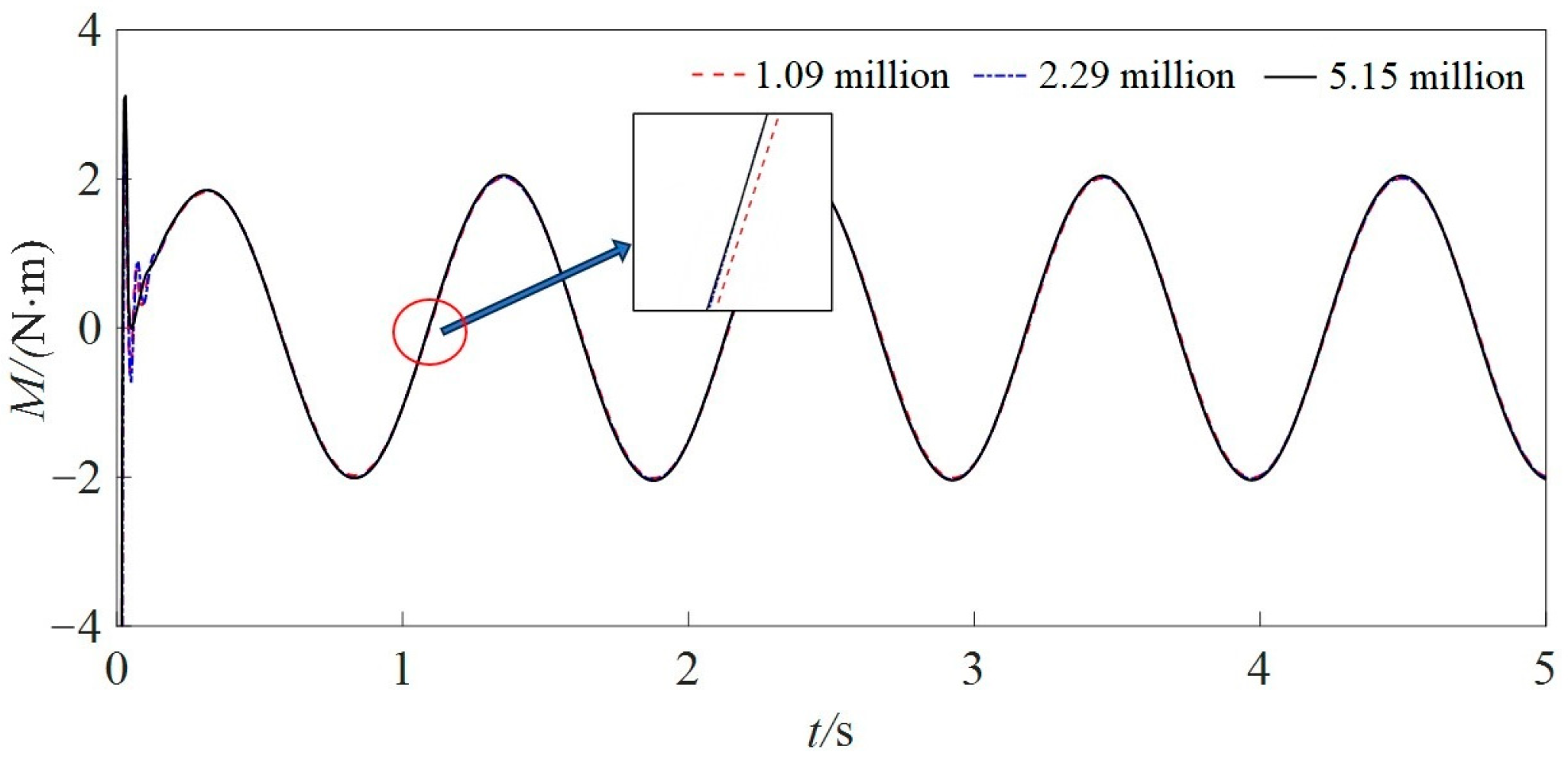
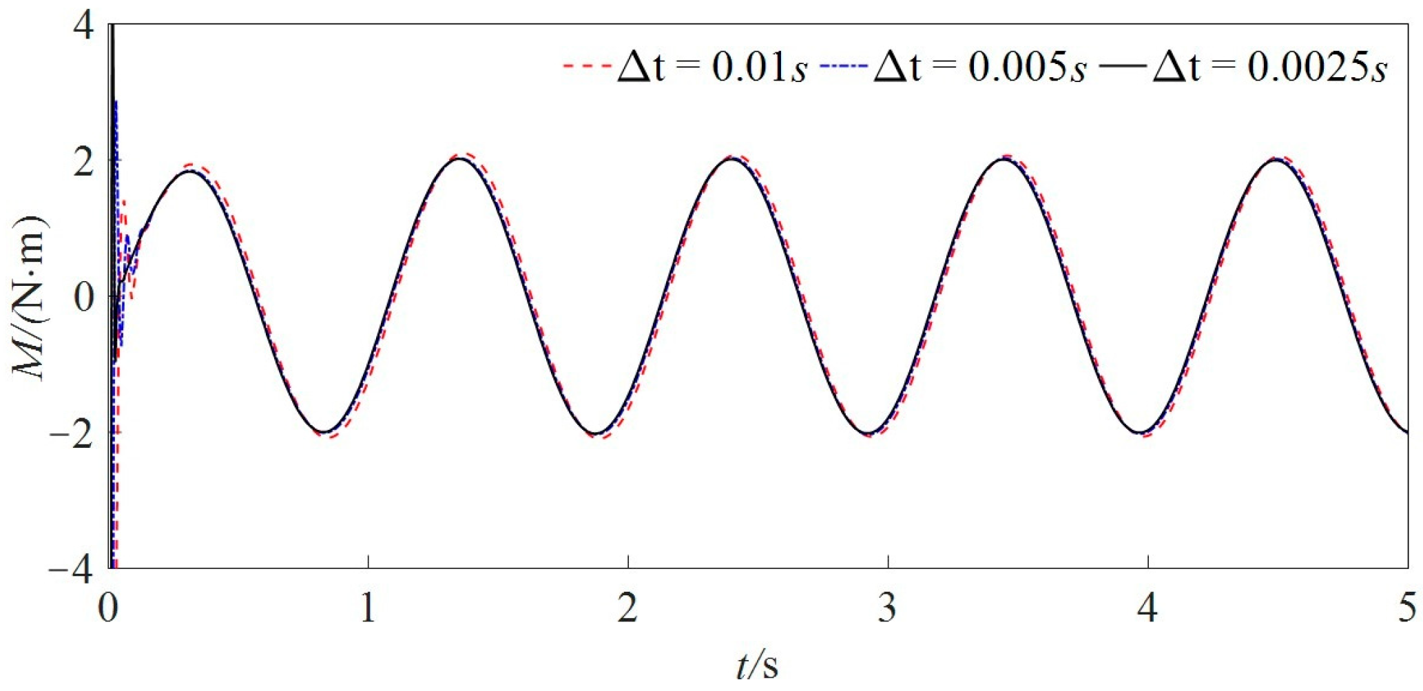
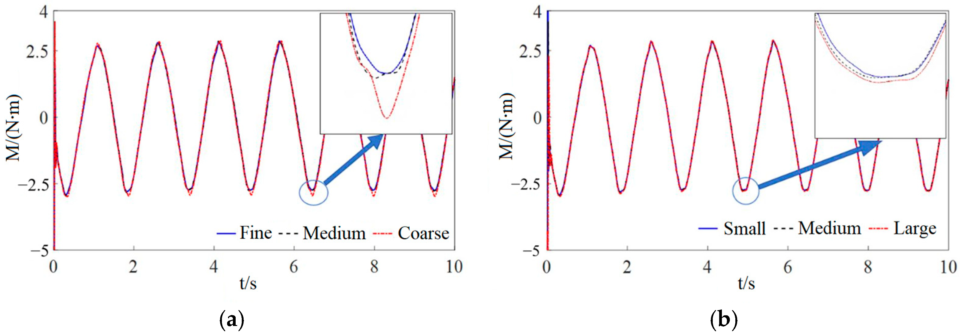
The grid convergence of the model was analyzed using three grid densities (1.09 million, 2.29 million, and 5.15 million cells) with a grid refinement ratio of r G = 2 and three time steps (0.01 s, 0.005 s, and 0.0025 s) with a time step refinement ratio of r G = 2 . The selected calculation condition was ϕ A = 5° and ω f = 6 rad/s. The time history curves of the hydrodynamic moment on the hull surface calculated under the three grid refinement ratios are shown in Figure 4. It can be seen that after a short period of unstable initial stage, the curves quickly enter a harmonic variation stage, and the stable segment approximates a harmonic function. In addition, the time history curves under the three grid sets are generally close, but the difference between the coarse grid and medium grid curves is significantly larger. Similar characteristics can be observed in the comparison of the time history curves with different time steps in Figure 5. The grid and time step settings used in the calculations are listed in Table 2 and Table 3.
The convergence analysis of the mesh and time step is performed according to the verification and confirmation analysis regulations of the ITTC [18]. The difference between adjacent meshes and time steps is calculated by the difference between roll dampers obtained by the formula, and the convergence factor is
R G = ε G 21 ε G 32 = 0.429 ,   R T = ε T 21 ε T 32 = 0.575
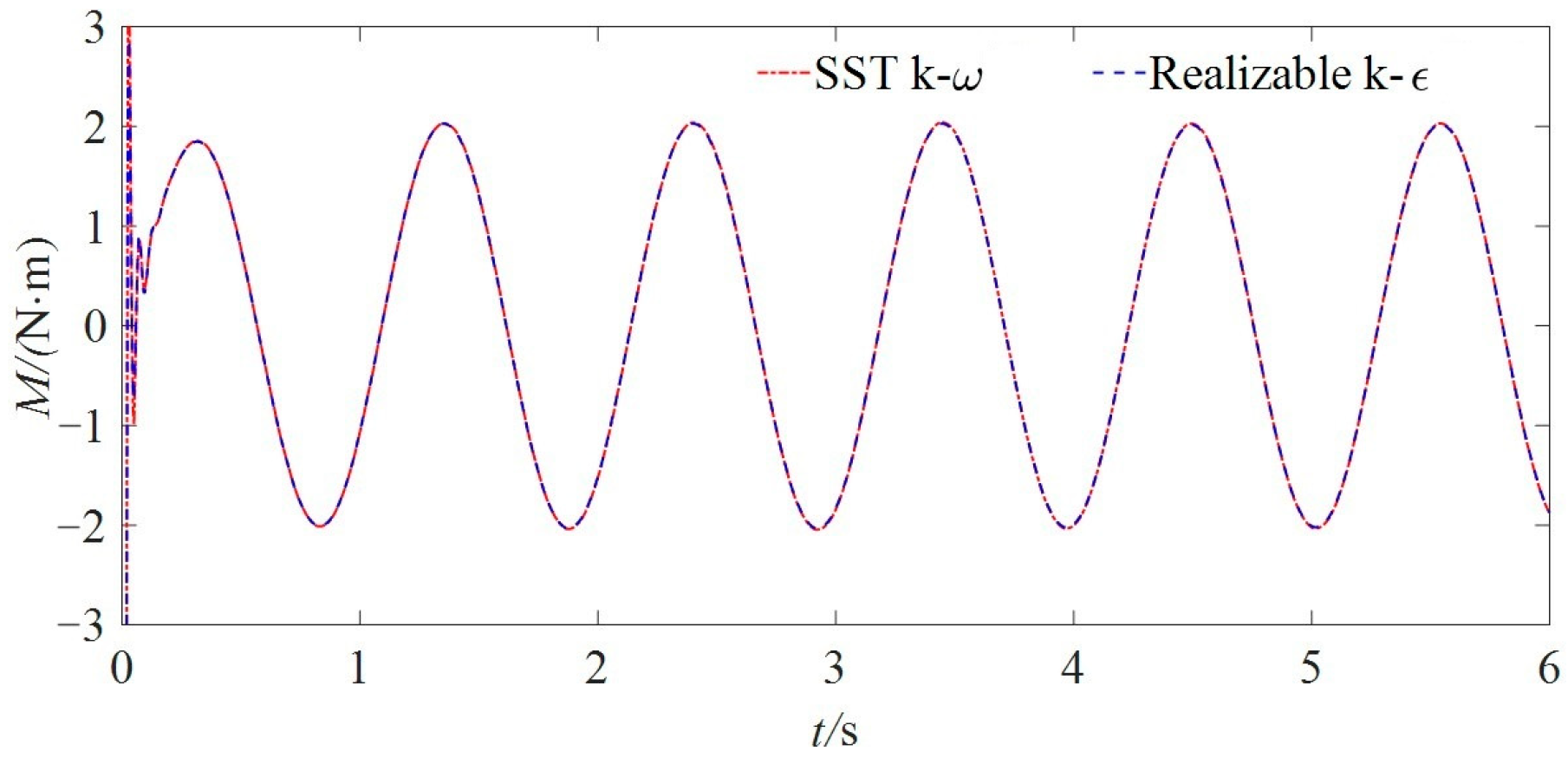
Since 0 < RG and RT < 1, the grid convergence condition is monotonic convergence. Furthermore, in order to verify the sensitivity of the turbulence model, the hydrodynamic moments on the hull surface under ϕA = 5°, ωf = 6 rad/s were calculated using the conditions of G2 and T2, as well as the Realizable k-ε bilayer model. The advantage of the Realizable k-ε double-layer model is that it can relax the height limit of the first layer grid on the wall. It can be applied to both low Reynolds number grids with y+ ≈ 1 and wall function grids with y+ ≥ 30. The comparison between the curves calculated by this model and those calculated by the SST k-ω model is shown in Figure 6. It can be seen that the calculation results of the hydrodynamic moment of the two turbulence models only have a slight difference in the initial unstable stage, and the curve amplitudes and phases after that are almost exactly the same. It can be seen that under the current model settings, the calculation results are not sensitive to the selection of turbulence models.
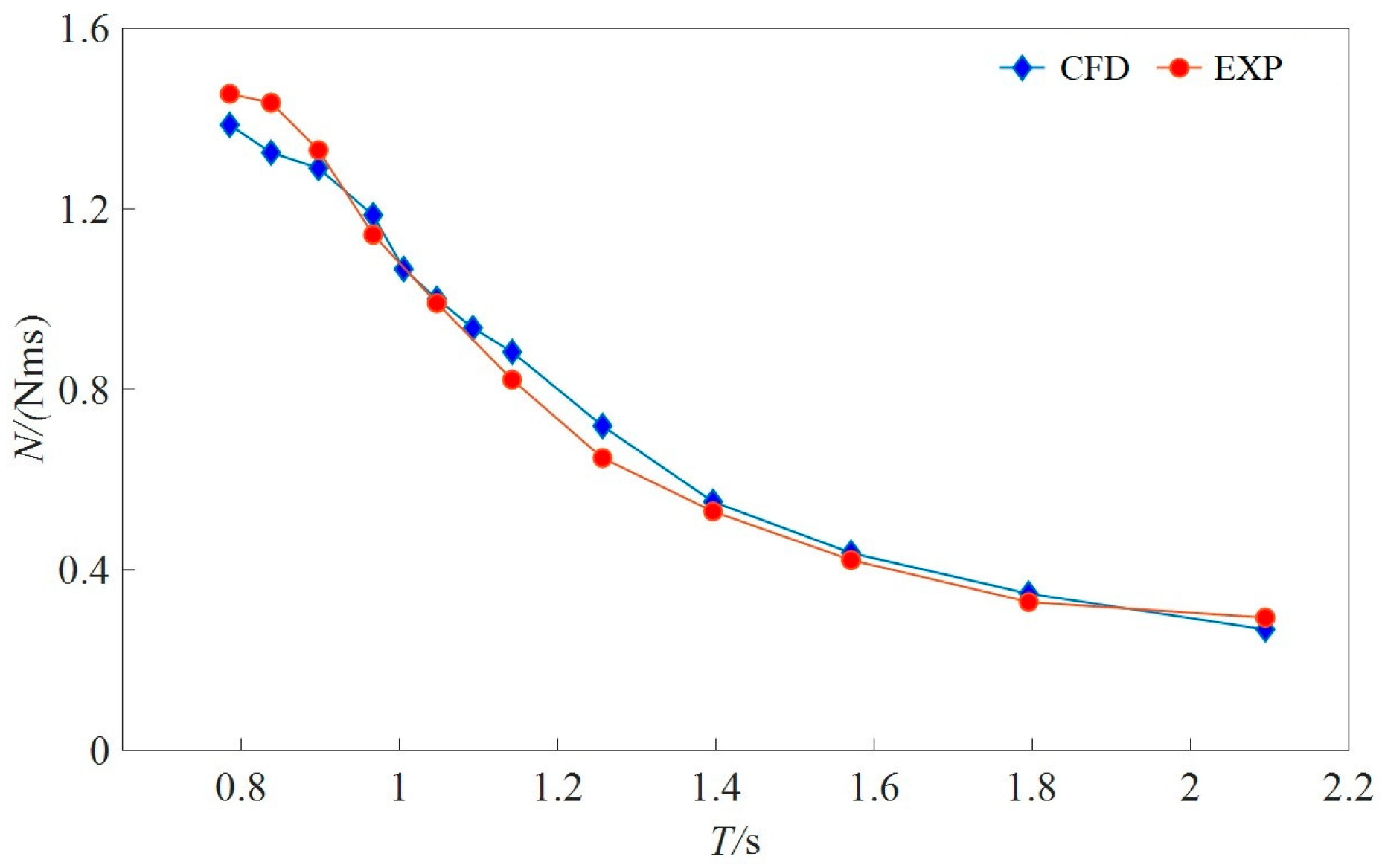
After verifying the convergence, numerical calculations were carried out according to the conditions of the forced roll model test provided in Vugts [19]. The calculated values and the test values are shown in Figure 7. It can be seen that the roll damping of the Series 60 model ship will increase with the increase in roll frequency. The comparison results show that the CFD simulation results are in good agreement with the experimental situation in terms of numerical values and changing trends.

3.3. Simulation Verification of Side-Opening Ships

To further verify the applicability of this calculation model to ships with side openings, numerical simulation was conducted on the damaged DTMB5415 ship model. This ship model is a 1:51 fiberglass reinforced plastic ship model adopted by Begovic [20] in 2013. The main dimensions of the model ship and the actual ship are shown in Table 4. The geometric shape of the ship is shown in Figure 8. As can be seen from Figure 8a, the damaged ship model was made by opening a hole on the starboard side of the standard DTMB5415 ship model. The flooding will cause corresponding changes in its static floating state. Specifically, the average draft of the model increased from 0.12 m to 0.145 m, and a trim by bow of 0.656 deg was generated. The compartment situation of this ship is shown in Figure 8b. It can be seen that the length of the opening on its side is less than that of the water inlet compartment. The bottom of the water inlet compartment has a double bottom, including two compartments, 1 and 2. The top of each compartment is connected to the deck by round holes to eliminate the influence of air compressibility when water enters it. The length of the water inlet compartment extends from 65.66 m to 90.02 m, accounting for 17% of the length between perpendiculars.
The simulated mesh division is shown in Figure 9. Since overlapping grids were adopted in the calculation, it is necessary to ensure that the dimensions at the junction of the background grid and the overlapping grids are similar. In addition, the volume mesh near the damaged compartment needs to be independently refined, and the surface mesh around the openings should be refined to preserve the complex hull surface as much as possible.
Three grid densities were selected with a grid refinement ratio of r G = 2 and three time steps were chosen with a time step refinement ratio of r T = 2 to analyze the calculation convergence of the forced roll model. The selected roll amplitude was 10°, and the roll period was the natural roll decay period of the damaged DTMB5415 ship model, which is 1.529 s. The ship moments calculated under the three grid refinement ratios are shown in Figure 10. It can be seen that the stabilized results exhibit a harmonic state; thus, a linearized damping model can be used to fit the hydrodynamic moment curve, ensuring the applicability of the damping model to this ship type. In addition, as shown in Figure 10, the time history results under the three grid sets are relatively close.
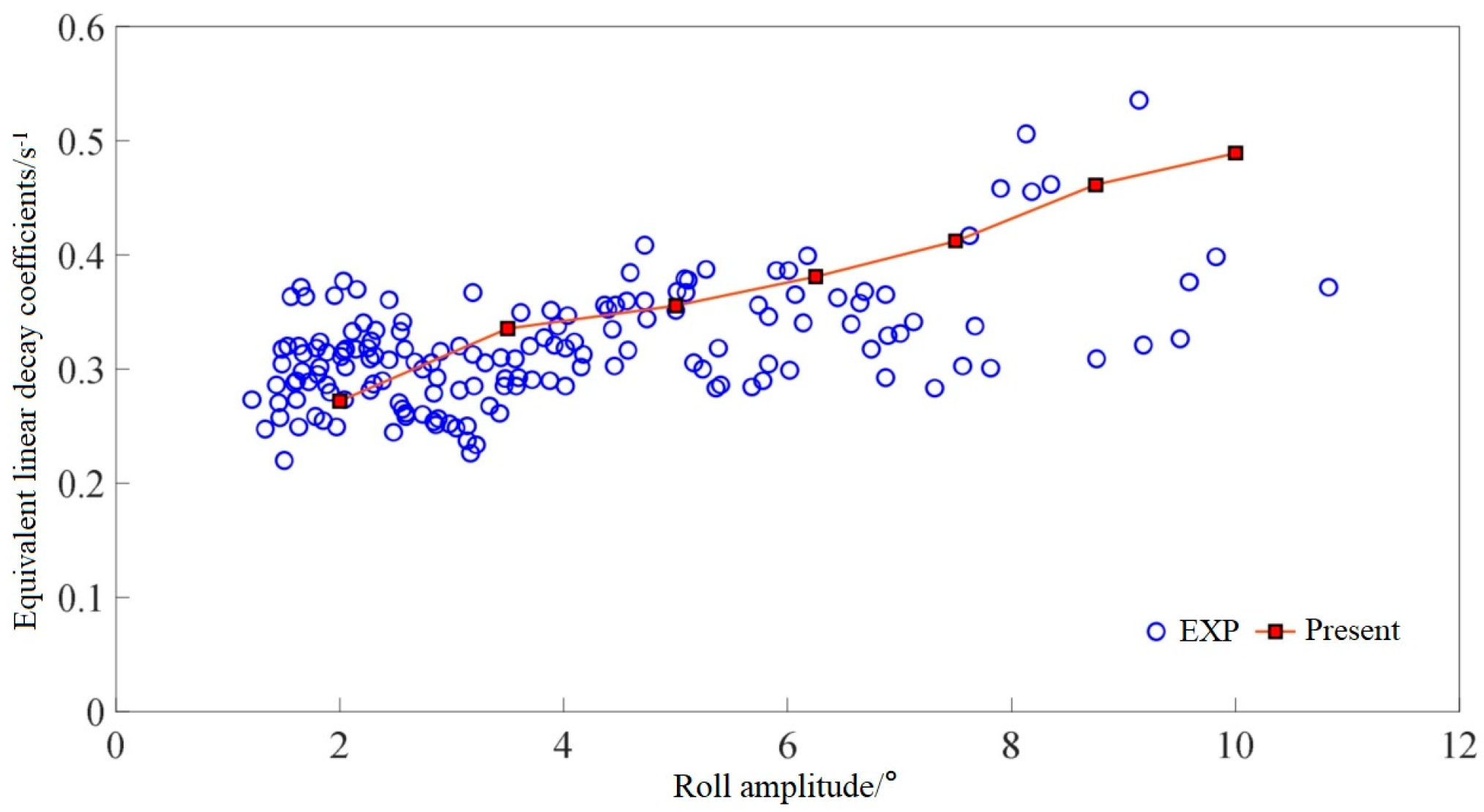
The roll amplitudes of 2°, 3.5°, 5°, 6.25°, 7.5°, 8.75°, and 10° were selected, and forced roll numerical simulations were conducted using the previously established medium grid and time step settings. The hydrodynamic moments acting on the wetted surface were monitored, and the roll damping N under each working condition was determined via trigonometric function fitting. To facilitate a comparison with existing experimental data, N was divided by 2 I x x + J x x to obtain the roll decay coefficient for each condition. Figure 11 presents the calculated coefficients under various working conditions and the experimental decay coefficients at different roll angles obtained by Begovic et al. It can be seen that both the trend and the magnitude are consistent, which proves the rationality of the numerical simulation method adopted in this paper.

4. Calculation and Analysis of Hydrodynamic Roll Moment

4.1. Free-Flooding Ship Model and Computational Domain Setup L

In order to analyze the characteristics of roll damping and added moment of inertia of the free-flooding aquaculture ship, the previously mentioned calculation model was used to conduct forced roll numerical simulations on a double-bottom single-shell free-flooding aquaculture ship and its hull in the closed state. The main parameters of the 1/50 scale model of the free-flooding ship used in this paper are shown in Table 5. This type of ship has two rows of upper and lower free-flooding openings on the hull side, enabling the aquaculture tanks to connect with the open sea and facilitating water exchange through the openings for aquaculture operations inside the tanks.
The STAR-CCM+ software was used to establish the fluid domain of the model. Based on overlapping grids, the computational domain was divided into background and overlapping regions, with mesh division similar to that in the previous section. In addition, to capture local complex flows, the volume and surface meshes at the openings were locally refined to 1/4 of the base size. As shown in Figure 12, the first diagram is the mesh division of the hull side, and the second is the cross-sectional view of the internal and external meshes in the overlapping region. The total number of meshes is about 4 million.

4.2. Calculation Results and Analysis of Ship Moments

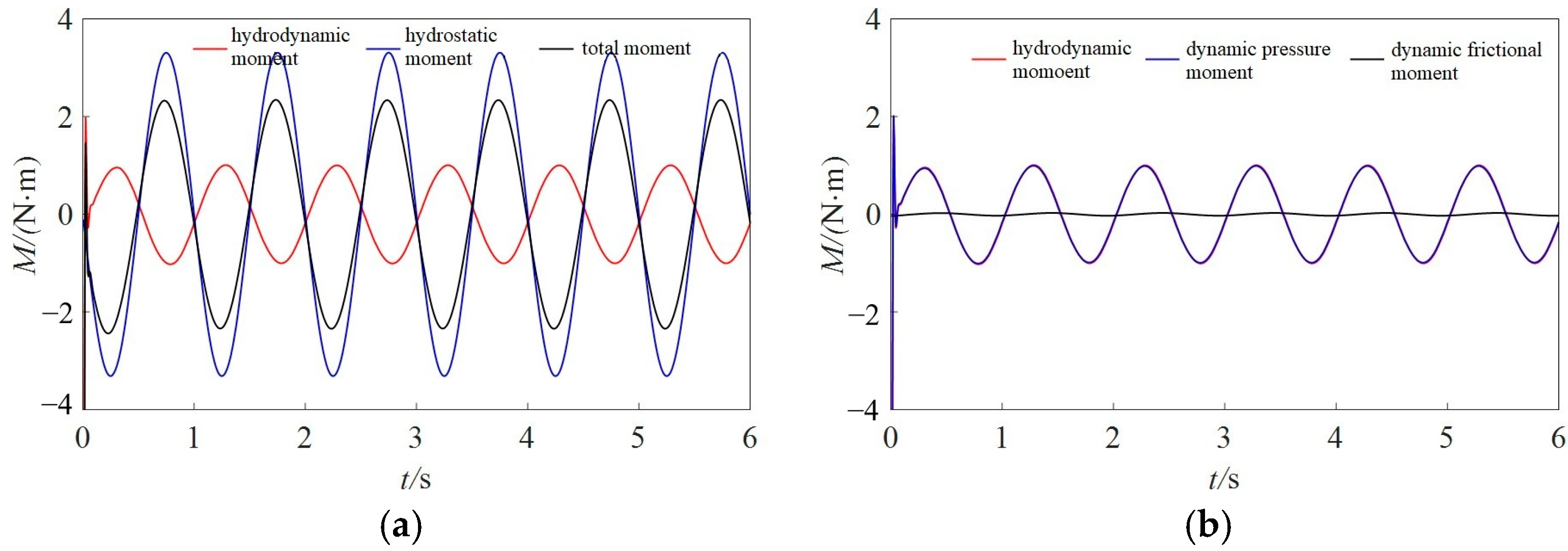
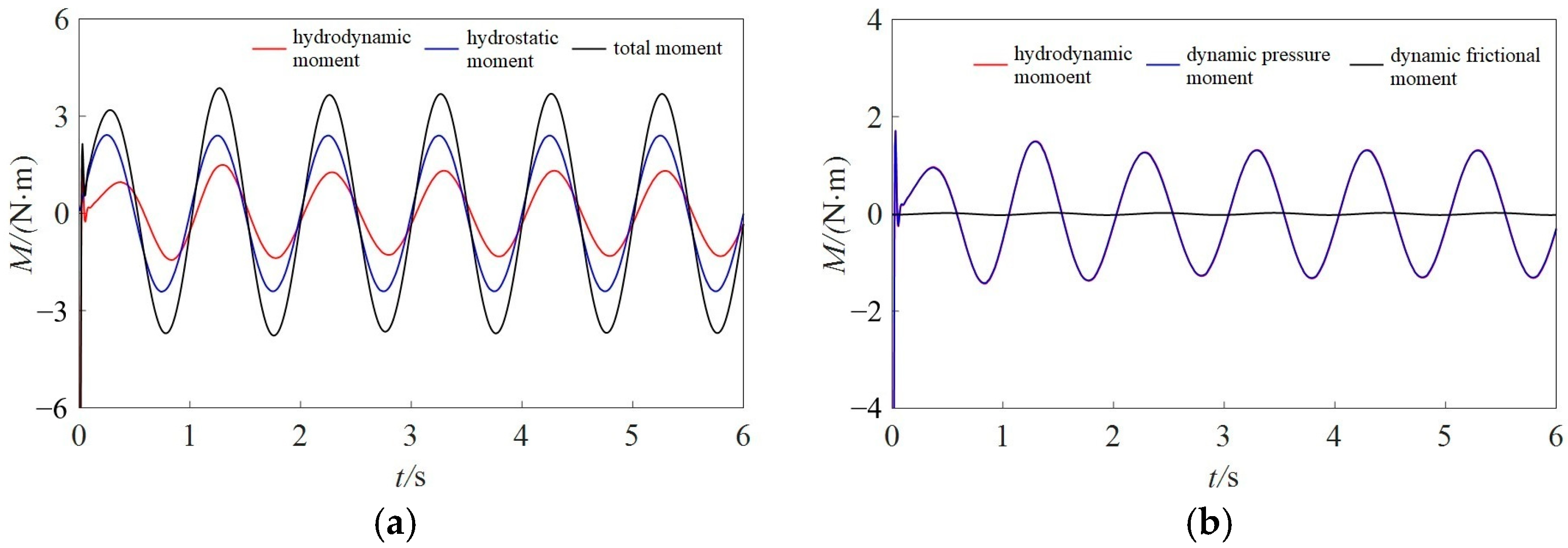
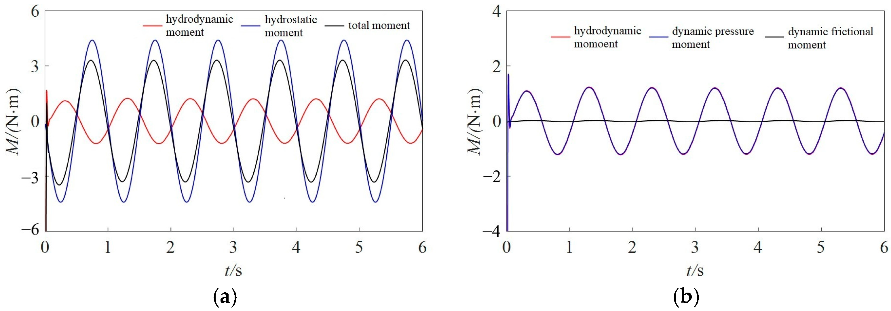
The hydrodynamic moments acting on the outer hull and internal liquid tanks of both the intact ship and the free-flooding ship were monitored, respectively. The roll amplitudes ϕA were set to 2.5°, 5°, and 7.5°, and the roll periods Tf were 1 s, 1.25 s, 1.5 s, 1.75 s, 2 s, 2.25 s, and 2.5 s. Subsequently, the roll damping and added moment of inertia of the ship model’s hull and liquid tanks under each working condition were calculated. Figure 13 and Figure 14 show the time history results of the roll moments acting on the outer hull and liquid tank of the free-flooding ship when ϕA = 5° and Tf = 1 s, respectively. The roll damping coefficient of the free-flooding ship can be obtained by fitting the stabilized results with a trigonometric function.
Figure 13a shows the hydrostatic moment, hydrodynamic moment, and total moment (combining both components) acting on the hull. Figure 13b presents the hydrodynamic moment on the outer hull, which can be decomposed into the dynamic pressure moment and frictional moment. It can be observed that the total moment on the outer hull of the free-flooding ship exhibits a phase difference of about π compared to the tank because the hydrostatic pressure moments on the outer hull and inner tank are opposite due to the opposite directions of fluid static pressure on the hull and tank. In addition, the hydrodynamic moment curves of the hull and tank are relatively close. The amplitude of the outer hull hydrodynamic moment is 1.002 N∙m, and that of the inner tank is 1.312 N∙m. It can be known through calculation that the roll damping of the outer hull is 0.349 N∙m∙s and that of the tank is 0.615 N∙m∙s. Furthermore, as shown in Figure 14b, compared with the pressure component, the frictional component in the hydrodynamic moment is small and slightly lagging in phase. Forced roll simulations were conducted on the intact ship. The time history of the roll moment acting on the outer hull under the conditions of ϕA = 5° and Tf = 1 s is shown in Figure 15. As can be seen from the figure, the force condition of the intact ship is relatively close to that of the outer hull of the free-flooding ship. However, since there are no openings on the hull surface, the amplitude of the hydrostatic moment acting on the intact ship is larger than that of the free-flooding ship. In addition, as shown in Figure 15, both the pressure resistance and frictional resistance on the surface of the intact ship are greater than those of the free-flooding ship with surface openings, resulting in a larger amplitude of the hydrodynamic moment on the outer hull of the intact ship compared to the free-flooding ship. The calculated roll damping of the outer hull of the intact ship is 0.793 N∙m∙s, which is also greater than that of the outer hull of the free-flooding ship.
At a roll amplitude of 5° and a roll period of 1 s, the evolution of the free surface of the intact ship and the free-flooding ship at 0.5 s, 1 s, and 1.5 s is shown in Figure 16, respectively. It can be observed that the water in the free-flooding tank produces relatively violent sloshing, and there is a large free surface height difference between the inside and outside of the tank. The effects of such sloshing and water exchange cause differences in the wave generation in the outer domain between the intact ship and the free-flooding ship.

4.3. The Roll Hydrodynamic Coefficients Under Different Operating Conditions

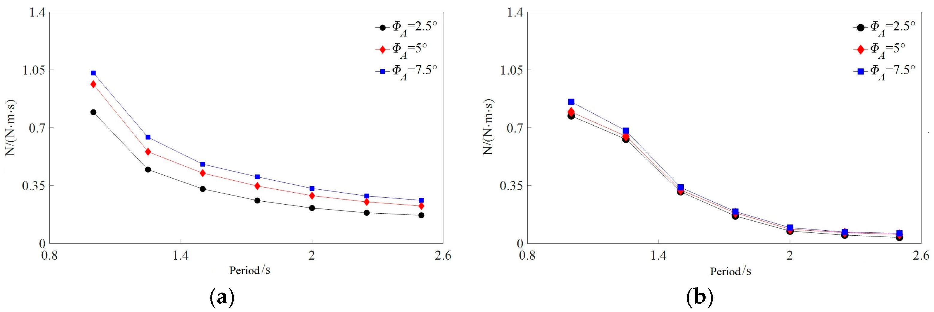
Based on the formulas in Section 2.2, the roll damping of the intact ship and free-flooding ship under different roll amplitudes and periods was calculated. As shown in Figure 17, the roll damping decreases with the increase in roll period. However, the roll damping of the free-flooding ship tends to increase more rapidly as the roll period decreases. In addition, as can be seen from Figure 17, the roll damping of both the intact ship and the free-flooding ship increases with the increase in roll amplitude, but the variation in roll amplitude has a more significant impact on the roll damping of the free-flooding ship compared to the intact ship.
The calculated added moment of inertia of the intact ship and free-flooding ship under different roll amplitudes is shown in Figure 18. It can be observed that the added moment of inertia varies relatively gently with the roll period. Furthermore, the increase in roll amplitude reflects changes in angular velocity and accelerated rotation of the hull, while the increased Jxx indicates enhanced fluid inertial resistance against the hull’s rotational motion.
The roll damping and added moment of inertia caused by the hull and tank of the free-flooding ship were calculated separately. Figure 19 is a comparison chart of roll damping considering the outer hull, free-flooding tank, and both parts simultaneously. It can be seen that for this free-flooding ship, the roll damping caused by the shear force and dynamic pressure on the tank wall is greater than that of the hull. In addition, as the roll period increases, both the outer hull roll damping and tank roll damping decrease slowly, but the tank roll damping changes more slowly, and its proportion of the total ship gradually increases. Additionally, both the outer hull and tank roll damping increase slightly with the increase in roll amplitude.
The added moment of inertia caused by the hull, tank, and entire ship roll motions of the free-flooding aquaculture ship at roll amplitudes of 2.5°, 5°, and 7.5° were compared, and the results are shown in Figure 20. It can be seen that the added moment of inertia of the hull and tank are numerically relatively close, and the results of each part vary relatively stably with the roll period. In addition, due to more intense fluid sloshing in the tank of the free-flooding ship, the numerical value of the tank’s roll added moment of inertia is greater than that of the hull.
Figure 21 shows the comparison results of roll damping between the outer hulls of the intact ship and the free-flooding ship. Due to the presence of side openings, the roll damping of the outer hull of the free-flooding ship is significantly smaller than that of the intact ship at lower periods. This may be related to the reduction in wall friction damping caused by the hull openings. However, as the roll period increases, the influence of hull openings on roll damping gradually diminishes, and the damping variations of the two types of hulls tend to converge.
Figure 22 presents the roll added moment of inertia of the hulls for the intact ship and the free-flooding ship, respectively. It can be seen that the roll added moment of inertia of the hulls for both the intact ship and the free-flooding ship varies relatively gently with the period and decreases slightly as the roll period increases. Furthermore, the results for the intact ship are generally larger than those for the free-flooding ship, which may be because the hull opening structure weakens the fluid “adhesion” to the hull during rolling.

4.4. The Influence of Ship Speed on Roll Hydrodynamic Coefficients

To investigate the influence of ship speed on roll hydrodynamic coefficients, forced roll numerical simulations were performed for the intact ship and free-flooding ship in different roll amplitudes, with a roll period of 1.5 s and Froude numbers (Fr) of 0.05, 0.1, and 0.15 respectively. The computational results are shown in Figure 23. It can be seen that ship speed has a significant impact on both the roll damping and roll added moment of inertia of both the free-flooding ship and the intact ship. As the speed increases, the hydrodynamic coefficients of both the intact ship and the free-flooding ship increase. The amplitude of increase in the roll added moment of inertia is nearly the same for both types of ships, while the roll damping of the free-flooding ship increases at a slower rate than that of the intact ship.

5. Conclusions

This paper conducted numerical simulations on the forced roll motion of free-flooding ships and obtained the roll damping and roll added moment of inertia through fitting calculations. In addition, the influence of the outer hull and inner tank on a series of roll hydrodynamic coefficients was studied, as well as their respective relationships with roll conditions, and the roll damping and roll added moment of inertia between the free-flooding ship and the intact ship were compared. The main conclusions can be summarized as follows:
(1)
CFD-based numerical simulations can reflect the roll hydrodynamic characteristics of free-flooding ships well and predict the forced roll motion of ships considering sloshing and fluid exchange at the openings.
(2)
Due to the presence of opening structures, the hydrostatic moment and hydrodynamic moment of the outer hull of the free-flooding ship are reduced compared to the intact ship. For both free-flooding and intact ships, the roll damping and roll added moment of inertia decrease with increasing roll period and increase with increasing roll amplitude. The increase in roll amplitude reflects changes in angular velocity and accelerated rotation of the hull, while the increase in the added moment of inertia indicates the enhanced influence of fluid inertia on the resistance to the hull’s rotational motion. For the aquaculture ship in this paper, the roll hydrodynamic coefficients of the tank are slightly larger than those of the outer hull.
(3)
The research on roll hydrodynamic coefficients in this paper can provide reference and correction for the calculation of roll motion prediction of free-flooding ships using potential flow methods. Furthermore, it can be seen that side openings have a significant impact on the internal and external flow fields and roll hydrodynamic coefficients during hull rolling. Subsequent studies on the size, number, and position of openings will help improve the hydrodynamic performance of free-flooding ships.

Author Contributions

Conceptualization, C.L. and R.Z.; Methodology, Y.T.; Software, C.L. and Y.T.; Validation, C.L. and Y.T.; Investigation, Y.T. and M.X.; Data Curation, C.L. and Y.T.; Writing-Review and Editing, M.X. and R.Z.; Supervision, R.Z. All authors have read and agreed to the published version of the manuscript.

Funding

This research was funded by Research on Environmental Load Technology and Normative Standards for Ships and Marine Engineering of China Classification Society, project number: CCS-2021-63.

Data Availability Statement

The original contributions presented in this study are included in this article. Further inquiries can be directed to the corresponding author.

Conflicts of Interest

Author Yuehu Teng was employed by the Marine Design and Research Institute of China. Author Min Xu was employed by the Shanghai Rules and Research Institute and the Ships and Offshore Installations Structural Safety Laboratory. The remaining authors declare that this research was conducted in the absence of any commercial or financial relationships that could be construed as a potential conflict of interest.

Abbreviations

The following abbreviations are used in this manuscript:
CFDComputational Fluid Dynamics
RANSReynolds-averaged Navier–Stokes
VOFVolume of Fluid
ITTCInternational Towing Tank Meeting

References

  1. Ikeda, Y. A prediction method for ship roll damping. In Report of Dept of Naval Architecture Osaka Prefecture University; Osaka Prefecture University: Sakai, Japan, 1978; p. 405. [Google Scholar]
  2. Korpus, R.A.; Falzarano, J.M. Prediction of Viscous Ship Roll Damping by Unsteady Navier-Stokes Techniques. J. Offshore Mech. Arct. Eng. 1997, 119, 108–113. [Google Scholar] [CrossRef]
  3. Zhang, H.; Liu, Y.; Miu, G. Vortex patterns and roll damping on various cross sections of ships. J. China Ocean. Eng. 2000, 14, 185–192. [Google Scholar]
  4. Huang, H.; Guo, H.; Zhu, R.; Mu, G. Computations of ship roll damping in viscous flow. J. Ship Mech. 2008, 12, 568–573. [Google Scholar]
  5. Zhu, R.; Guo, H.; Miu, G.; Yu, J. A computational method for evaluation of added mass and damping of ship based on CFD theory. J. Shanghai Jiaotong Univ. 2009, 43, 198–203. [Google Scholar]
  6. Jaouen, F.; Koop, A.; Vaz, G. Predicting roll added mass and damping of a ship hull section using CFD. In Proceedings of the ASME 2011 30th International Conference on Ocean, Rotterdam, The Netherlands, 19–24 June 2011; Volume 7, pp. 105–115. [Google Scholar]
  7. Yang, C. Research and Application of Key Techniques for Ship Performance Numerical Tank. Ph.D. Thesis, Shanghai Jiaotong University, Shanghai, China, 2014. [Google Scholar]
  8. Jiang, Y.; Zhu, R.; Miu, G.; Yang, C. Damping prediction of a rolling ship with bilge keel in viscous flow based on numerical simulation. Shipbuild. China 2016, 57, 1–12. [Google Scholar]
  9. Begovic, E.; Day, A.H.; Incecik, A. An experimental study of hull girder loads on an intact and damaged naval ship. Ocean. Eng. 2017, 133, 47–65. [Google Scholar] [CrossRef]
  10. Mancini, S.; Begovic, E.; Pizzirusso, D.; Day, A.H.; Incecik, A. Roll damping assessment of intact and damaged ship by CFD and EFD methods. In Proceedings of the 12th International Conference on the Stability of Ships and Ocean Vehicles, Glasgow, UK, 14–19 June 2015. [Google Scholar]
  11. Xu, S.; Huang, Z.; Gao, Z. On characteristics and interpolation method of roll hydrodynamic coefficients for damaged ships. Ship Boat 2022, 33, 75–81. [Google Scholar]
  12. Huang, Z.; Gao, Z.; Xu, S. Calculation and analysis of rolling hydrodynamic coefficients for damaged ship. Shipbuild. China 2023, 64, 151–163. [Google Scholar]
  13. Gao, Q.; Vassalos, D. Numerical study of damage ship hydrodynamics. Ocean. Eng. 2012, 55, 199–205. [Google Scholar] [CrossRef]
  14. Manderbacka, T.; Ruponen, P.; Kulovesi, J.; Matusiak, J. Model experiments of the transient response to flooding of the box shaped barge. J. Fluids Struct. 2015, 57, 127–143. [Google Scholar] [CrossRef]
  15. Wu, J.; Chen, Z. Coupled Motion of Tank Sloshing and Aquaculture Platform in Regular Beam Sea. Ship Eng. 2021, 43, 17–23. [Google Scholar]
  16. STAR-CCM+, Version 2310.0001-R8 (18.06.007-R8); Siemens Digital Industries Software: Plano, TX, USA, 2023.
  17. Todd, F.H. Series 60 methodical experiments with models of single-screw merchant ships. Nav. Eng. J. 2010, 76, 492. [Google Scholar]
  18. ITTC. Uncertainty Analysis in CFD Verification and Validation, Methodology and Procedures; ITTC: Wuxi, China, 2017; 7.5-03-01-01, Revision 03; pp. 1–13. [Google Scholar]
  19. Vugts, J.H. The Hydrodynamic Forces and Ship Motions in Waves; Delft University of Technology: Delft, The Netherlands, 1970. [Google Scholar]
  20. Begovic, E.; Mortola, G.; Incecik, A.; Day, A.H. Experimental assessment of intact and damaged ship motions in head, beam and quartering seas. Ocean. Eng. 2013, 72, 209–226. [Google Scholar]
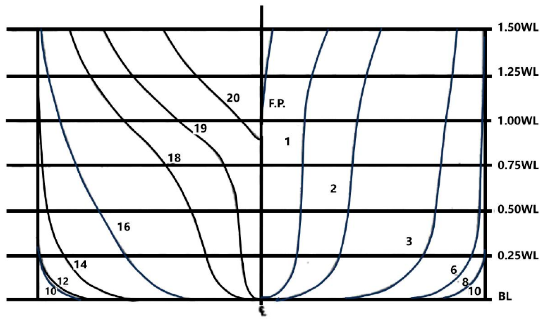
Figure 1. Body plan of Series 60 ship.
Jmse 13 01857 g001
Figure 2. The mesh generation: (a) axonometric plot; (b) mid transverse section; (c) bow of the ship.
Jmse 13 01857 g002
Figure 3. Computational domain partitioning.
Jmse 13 01857 g003
Figure 4. Time history of hydrodynamic moment acting on the hull under different grid numbers.
Jmse 13 01857 g004
Figure 5. Time history of hydrodynamic moment acting on the hull under different time steps.
Jmse 13 01857 g005
Figure 6. Time history of ship hydrodynamic moment computed using two turbulence models.
Jmse 13 01857 g006
Figure 7. Computed and experimental values of roll damping for ship models under different roll periods.
Jmse 13 01857 g007
Figure 8. Model of damaged DTMB5415: (a) model of whole ship; (b) model of damaged compartment.
Jmse 13 01857 g008
Figure 9. Computational domain and mesh division: (a) boundary of background region; (b) mesh on overset region.
Jmse 13 01857 g009
Figure 10. Convergence analysis of calculation parameters: (a) rolling moment on the hull under different grid numbers; (b) rolling moment on the hull under time step sizes.
Jmse 13 01857 g010
Figure 11. Comparison figure between computed and experimental values.
Jmse 13 01857 g011
Figure 12. Mesh of the free-flooding breeding ship: (a) ship surface mesh; (b) side mesh.
Jmse 13 01857 g012
Figure 13. The roll moment of the outer hull of the free-flooding ship: (a) total moment and its components; (b) hydrodynamic moment and its components.
Jmse 13 01857 g013
Figure 14. The roll moment of the inner tank of the free-flooding ship: (a) total moment and its components; (b) hydrodynamic moment and its components.
Jmse 13 01857 g014
Figure 15. The roll moment of the outer hull of the intact ship: (a) total moment and its components; (b) hydrodynamic moment and its components.
Jmse 13 01857 g015
Figure 16. The free surface amplitude in the calculation domain, where 1~3 correspond to time steps of 0.5 s, 1 s, and 1.5 s: (a) intact ship; (b) free-flooding ship.
Jmse 13 01857 g016
Figure 17. The roll damping of the free-flooding ship and intact ship under different roll angles and periods: (a) free-flooding ship; (b) intact ship.
Jmse 13 01857 g017
Figure 18. The added roll moment of inertia of the free-flooding ship and intact ship under different roll angles and periods: (a) free-flooding ship; (b) intact ship.
Jmse 13 01857 g018
Figure 19. The roll damping results of the hull, tank, and entire ship of a free-flooding ship in different roll amplitudes: (a) ϕA = 2.5°; (b) ϕA = 5°; (c) ϕA = 7.5°.
Jmse 13 01857 g019
Figure 20. The added roll moment of inertia results of the hull, tank, and entire ship of a free-flooding ship in different roll amplitudes: (a) ϕA = 2.5°; (b) ϕA = 5°; (c) ϕA = 7.5°.
Jmse 13 01857 g020
Figure 21. The roll damping results of the hull of free-flooding ship and intact ship in different roll amplitudes: (a) ϕA = 2.5°; (b) ϕA = 5°; (c) ϕA = 7.5°.
Jmse 13 01857 g021
Figure 22. The added roll moment of inertia results of the hull of free-flooding ship and intact ship in different roll amplitudes: (a) ϕA = 2.5°; (b) ϕA = 5°; (c) ϕA = 7.5°.
Jmse 13 01857 g022
Figure 23. Comparison of the roll hydrodynamic coefficients between intact ship and free-flooding ship with varying speeds in different cases: (a) roll damping; (b) additional moment of inertia.
Jmse 13 01857 g023
Table 1. Series 60 full-scale ship and model ship main parameters.
ParameterFull-Scale ShipModel Ship
L w l (m)123.9623.101
L p p (m)121.9203.048
B (m)17.4160.435
T (m)6.9680.174
C B 0.700.70
  ( m 3 ) 10,4560.121
Table 2. Mesh settings.
Grid Type(m)
Coarse G30.283
Medium G20.200
Fine G10.141
Table 3. Time step settings.
Time Step Type(s)
Large T30.01
Medium T20.005
Small T10.0025
Table 4. Main parameters of real and model ship for damaged DTMB5415.
ScaleLpp (m)B (m)D (m)T (m)△ (t, kg)KG (m)LCG (m)Kxx (m)
full-scale ship142.219.08212.476.1586357.55570.1376.12
model ship2.7880.3740.2440.1263.50.1481.3750.12
Table 5. Main parameters of ship and model of a free-flooding ship.
ParameterFull-Scale ShipModel Ship
L o a (m)98.171.963
L p p (m)89.951.800
B (m)18.80.376
T (m)8.9980.18
D (m)12.90.258
△ (t)53630.0429
Disclaimer/Publisher’s Note: The statements, opinions and data contained in all publications are solely those of the individual author(s) and contributor(s) and not of MDPI and/or the editor(s). MDPI and/or the editor(s) disclaim responsibility for any injury to people or property resulting from any ideas, methods, instructions or products referred to in the content.