Article

Improving ICP-Based Scanning Sonar Image Matching Performance Through Height Estimation of Feature Point Using Shaded Area

by
Gwonsoo Lee
1,
Sukmin Yoon
2,
Yeongjun Lee
3 and
Jihong Lee
4,*
1
Research Institute of Future Mobility System, Chungnam National University, Daejeon 34134, Republic of Korea
2
Hanwha Systems, Gumi 39376, Republic of Korea
3
Korea Research Institute of Ships and Ocean Engineering (KRISO), Daejeon 34103, Republic of Korea
4
Department of Mechatronics Engineering, Chungnam National University, Daejeon 34134, Republic of Korea
*
Author to whom correspondence should be addressed.
J. Mar. Sci. Eng. 2025, 13(1), 150; https://doi.org/10.3390/jmse13010150
Submission received: 7 December 2024 / Revised: 3 January 2025 / Accepted: 14 January 2025 / Published: 16 January 2025
(This article belongs to the Special Issue Unmanned Marine Vehicles: Navigation, Control and Sensing)

Abstract

:
This study presents an innovative method for estimating the height of feature points through shaded area analysis, to enhance the performance of iterative closest point (ICP)-based algorithms for matching scanning sonar images. Unlike other sensors, such as forward looking sonar (FLS) or BlueView, scanning sonar has an extended data acquisition period, complicating data collection while in motion. Additionally, existing ICP-based matching algorithms that rely on two-dimensional scanning sonar data suffer from matching errors due to ambiguities in the nearest-point matching process, typically arising when the feature points demonstrate similarities in size and spatial arrangement, leading to numerous potential connections between them. To mitigate these matching ambiguities, we restrict the matching areas in the two images that need to be aligned. We propose two strategies to limit the matching area: the first utilizes the position and orientation information derived from the navigation algorithm, while the second involves estimating the overlapping region between the two images through height assessments of the feature points, facilitated by shaded area analysis. This latter strategy emphasizes preferential matching based on the height information obtained. We propose integrating these two approaches and validate the proposed algorithm through simulations, experimental basin tests, and real-world data collection, demonstrating its effectiveness.

1. Introduction

The development of unmanned vehicles for military purposes is aimed toward resolving the significant challenges encountered in direct human intervention in mission-critical areas that are difficult to access, such as underwater environments, and in perilous situations such as handling explosives [1,2]. A pertinent example of this challenge is the detection and removal of sea mines. The inherent danger of approaching and neutralizing these explosive devices, which have the potential to obliterate and incapacitate large vessels with a single detonation, cannot be undermined. Moreover, these mines are frequently situated in remote locations, including offshore and submerged locations or along beaches [3].
To address these hazards, extensive research and development efforts have been directed toward unmanned vehicles designed specifically for mine detection and clearance, both within domestic and international contexts [4,5]. Nonetheless, the majority of unmanned vehicles currently available for these applications utilize propeller-type thrusters. This design choice inherently limits their underwater mobility and renders them ineffective in environments characterized by strong tidal flows or currents [6,7,8,9,10,11]. In response to these limitations, we are developing an advanced multijointed composite mobile underwater robot, capable of both swimming in the water column and traversing the seafloor, as depicted in Figure 1 [6,7,8,9,10,11]. Furthermore, we are developing innovative technologies aimed at the detection and identification of both surface-laid and buried mines using this versatile robotic platform.
Since articulated multijoint underwater robots that can walk on the seafloor are physically more proximate to the seafloor than typical propeller-type unmanned vehicles, the velocity measurement performance of Doppler velocity logger (DVL) and the orientation measurement performance of geomagnetic sensors (digital compass) are likely to be degraded by seafloor geology or marine debris owing to the short measurement distance and suspended particles on the seafloor. Consequently, the position estimation performance of the underwater robot deteriorates under such conditions. To mitigate these challenges, we intend to develop a multijoint composite mobile undersea robot that is equipped with an array of advanced position estimation sensors. This robot incorporates five navigation sensors dedicated to position and orientation estimation through inertial navigation: an inertial measurement unit (IMU), a DVL, digital compass, sound velocity sensor (SVS), and global positioning system (GPS) [12]. Furthermore, it is equipped with an ultrashort baseline (USBL) system for accurate underwater positioning [13,14,15], along with a 3D multiBeam echoSounder (3D-MBES) [16,17] and scanning sonar [18,19] for effective seafloor mapping and relative navigation. The relative position of the robot is determined by correlating the scanned sonar images with the estimated translational and rotational changes occurring during the matching process. The scanning sonar employed can capture high-resolution sonar images over a considerable range (up to 100 m); however, the image acquisition process is time-intensive, requiring approximately 25–30 min to obtain detailed images. This extended duration poses a challenge for continuous image acquisition while the robot is in motion. Consequently, it is essential to acquire scanning sonar images while stationary, followed by subsequent collection after the robot has commenced motion. To match the scanning sonar images and estimate their relative positions, a significant overlap between the acquired images is considered advantageous, which, however, is constrained by the image acquisition time. In addition, as the acquired data contain two-dimensional image information, this poses challenges when employing iterative closest point (ICP) algorithms based on three-dimensional information. To mitigate these challenges, prior research has introduced techniques for determining the overlapping regions in two sonar images based on position and orientation estimations derived from navigation algorithms. This is subsequently followed by sonar image matching based on topological descriptors, which focus on the features [20]. Alternatively, researchers have suggested employing pixel intensities from two-dimensional images to construct three-dimensional representations that can effectively minimize noise before employing ICP algorithms for matching purposes [21]. Nonetheless, topological descriptor-based matching algorithms are limited when dealing with small or non-elliptical configurations, as the feature points must collectively form an ellipse of a predefined minimum size. In addition, the accuracy is low because multiple feature points are counted as a single combination. However, topological descriptor-based matching algorithms [20] cannot be used for small or non-elliptical descriptors because the descriptors must form an ellipse of a certain size. This requirement not only constrains the versatility of such algorithms but also leads to reduced accuracy, as multiple feature points may be erroneously aggregated into a single combination. In contrast, ICP-based matching algorithms [21] assess features on an individual basis rather than as a singular descriptor, thereby facilitating matching irrespective of the distribution or shape of the features involved. However, both methods rely on the accurate estimation of overlapping regions to perform well, which can cause matching difficulties, especially in the presence of numerous features of similar size and arrangement. When inertial navigation systems exhibit significant errors and fail to distinctly define overlapping regions, the likelihood of incorrect matching increases. To address this issue, our study introduces a method aimed at enhancing the accuracy of overlapping region estimations. In scanning sonar imagery, shaded areas frequently emerge alongside the identifiable features. These shaded regions signify areas where sonar signals are obstructed by specific objects, preventing them from reaching the rear side of the object. This phenomenon is analogous to the formation of shadows caused by light on the ground. By leveraging the information available in a scanning sonar image, these shaded areas can be utilized to estimate the heights of feature points, thereby improving the matching process by incorporating three-dimensional information.
The methodology we propose is outlined as follows, and it will be rigorously tested and validated through simulations, basin experiments, and real-world experimental data:
1.
Estimation of shaded area length: A technique is introduced to estimate the length of the shaded areas by transforming the image data obtained from the Cartesian coordinate system into the cylindrical coordinate system, accounting for the inherent characteristics of sonar.
2.
Integration of matching algorithms: We propose a novel approach that integrates the existing ICP-based image matching algorithm with an additional matching algorithm that uses height estimations of feature points derived from the shaded areas.
The differences in the shaded area according to the object height are verified through simulation data, and the algorithm for the height estimation of feature points using the shaded area is validated using basin experimental data. This comprehensive methodology aims to significantly enhance the precision of overlapping region estimations in scanning sonar applications. The feasibility of the proposed method was rigorously assessed by integrating the existing ICP-based image matching algorithm with the height estimation of feature points derived from shaded areas using real-world experimental data for validation. The remainder of this paper is organized as follows: In Section 2, we detail the characteristics of the underwater sonar and scanning sonar systems employed in this study. This section introduces a shaded area estimation method that accounts for sonar-specific characteristics, and it also includes simulations that verify the variations in shaded areas as they relate to the height of objects. The novel fusion method that combines the traditional ICP-based matching algorithm with a matching algorithm leveraging the shaded area-based height estimation of feature points is proposed in Section 3. In Section 4, we present the results of validating the matching algorithm that incorporates the shaded area-based height estimation. This section details the experimental setup, including the data obtained from a controlled basin experiment, and the scanning sonar images utilized to validate the method introduced in Section 3. Additionally, we compare the matching results of our proposed method against other existing methods to highlight its efficacy. Finally, the practical implications of the proposed method and potential avenues for future research are summarized in Section 5.

2. Characteristic of Sonar and Shaded Area

2.1. Characteristics of Sonar

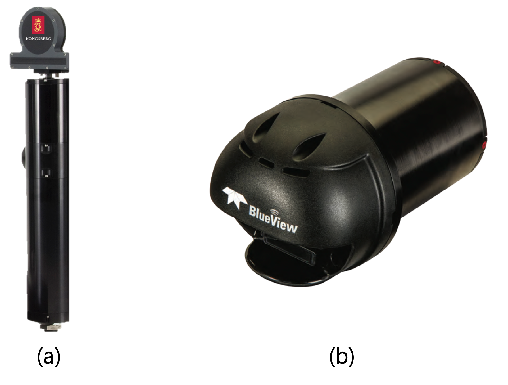
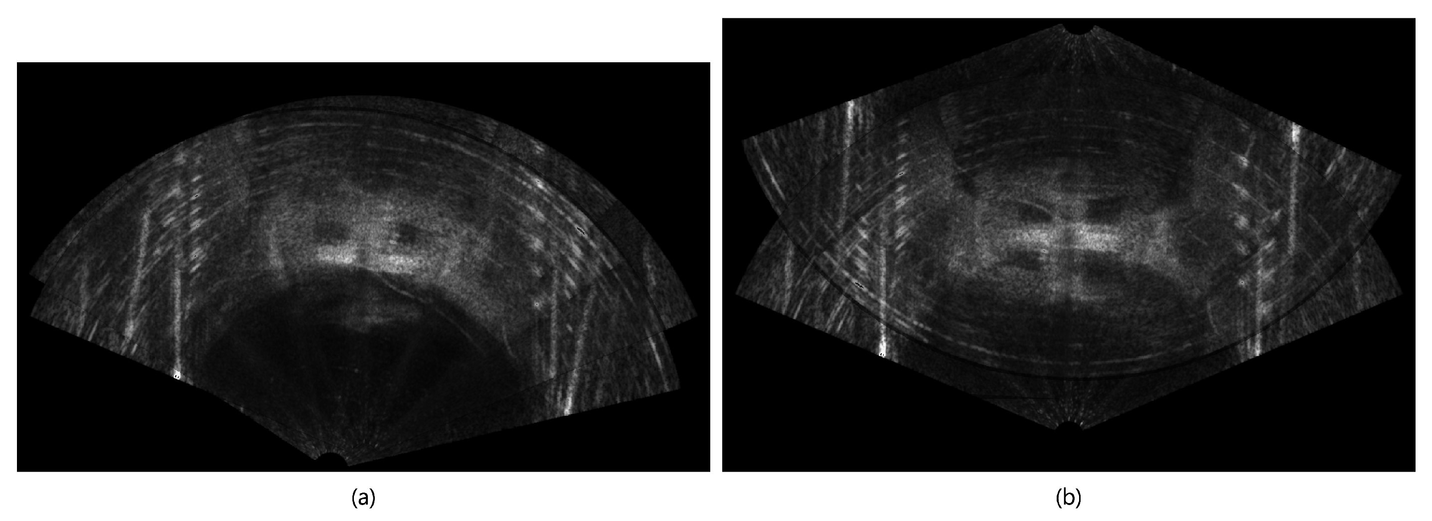
In this study, we employed two distinct types of sonar technology: Kongsberg’s 1171 high-resolution scanning sonar (Kongsberg, Horten, Norway) [18] and Teledyne’s M900-2250-130 (BlueView) (Teledyne Technologies, Thousand Oaks, CA, USA) [22,23]. Both sensors were designed to visualize the underwater environment in two-dimensional images. In Figure 2, panel (a) showcases the scanning sonar, while panel (b) presents the BlueView system. However, owing to their two-dimensional visualization capabilities, these sensors cannot accurately discern the height of submerged objects. This limitation contrasts with the functionalities of 3D-LiDAR systems [24], which are utilized on land, and 3D-MBESs [16,17], which are employed underwater. A notable consequence of this two-dimensional representation is that objects located at varying elevations but sharing identical bearings and distances (Figure 3) are perceived as a single object [25,26]. Although there have been existing methods that estimate height using shadow regions [27,28,29], these studies typically rely on continuous images captured by BlueView or results obtained from images taken at different angles to convert 2D images into 3D models. Such approaches were not used in this study.
Additionally, there exists an inherent shaded area where ultrasonic waves do not interact with an object, as depicted in Figure 4. This phenomenon introduces uncertainty regarding the presence of any lower-height objects situated within the shaded area, potentially obscured by those at greater heights [25]. Although the outputs from these two sonar devices ultimately manifest as circular or fan-shaped images within a Cartesian coordinate system, the underlying sensing process is fundamentally rooted in a cylindrical coordinate system. Therefore, for the aforementioned shaded area mentioned above, it is advantageous to estimate it in the cylindrical coordinate system for shaded area estimation, because it will occur continuously in the direction of r increasing at the same theta ( θ ) when observed in the cylindrical coordinate system.

2.2. Observing the Shaded Area Through Simulation

Herein, we used a UUV simulator (version 0.6.13) with the robot operating system (ROS) framework [30], which is accessible at https://github.com/uuvsimulator/uuv_simulator (accessed on 1 January 2025). As illustrated in Figure 5a, a series of cylinders with uniform diameters but differing heights were strategically arranged, and sonar images were captured from various vantage points. The outcomes of these observations are depicted in Figure 5b. The length of the shaded area is influenced by both the height of the object and the distance between the object and the sonar sensor. Moreover, Figure 5c showcases the results of transforming the data from Cartesian coordinates to cylindrical coordinates, revealing that the shaded area consistently expands in the direction of increasing r at a constant θ [31].

3. Proposed Matching Algorithm

3.1. An Overview of the Proposed Algorithm

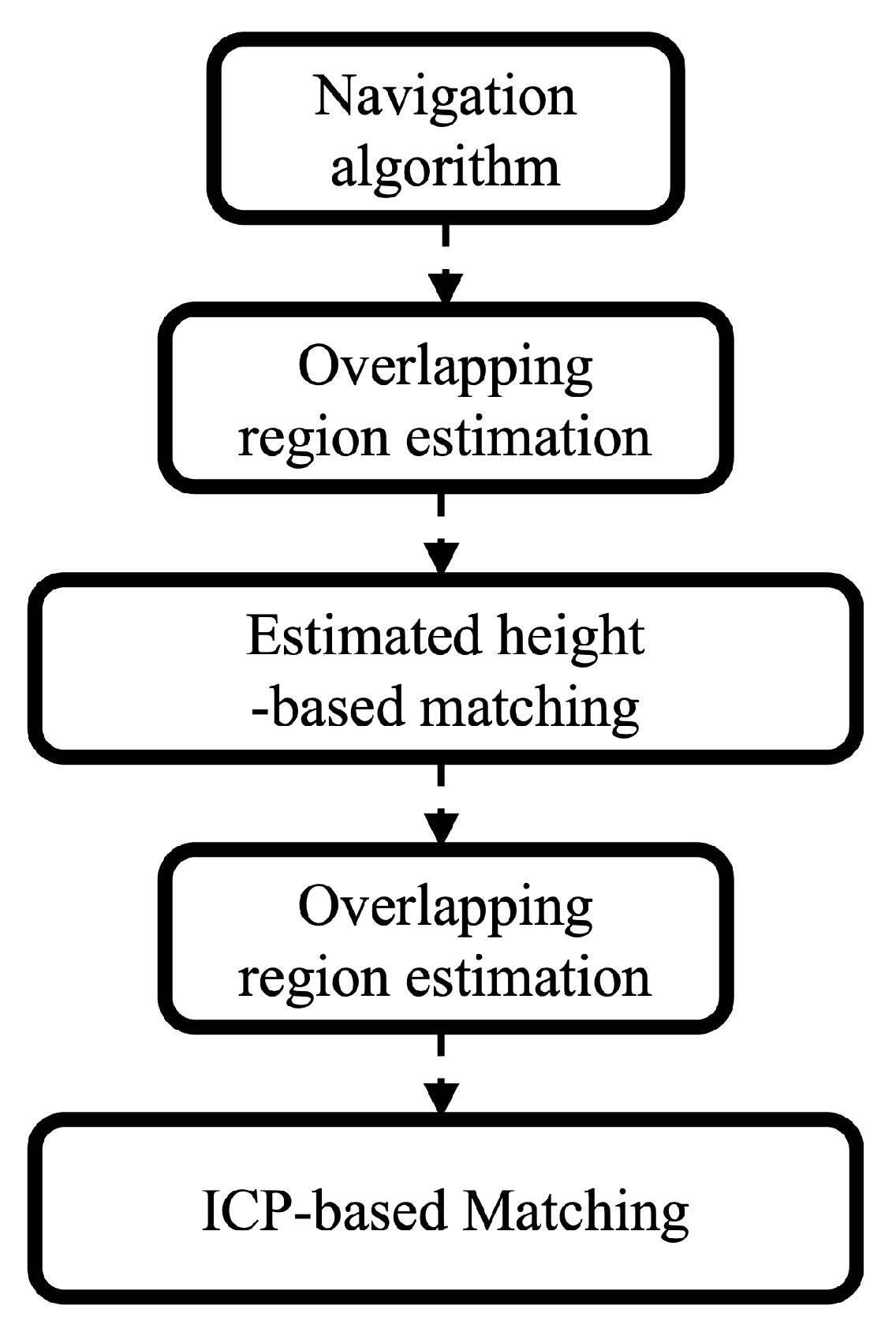
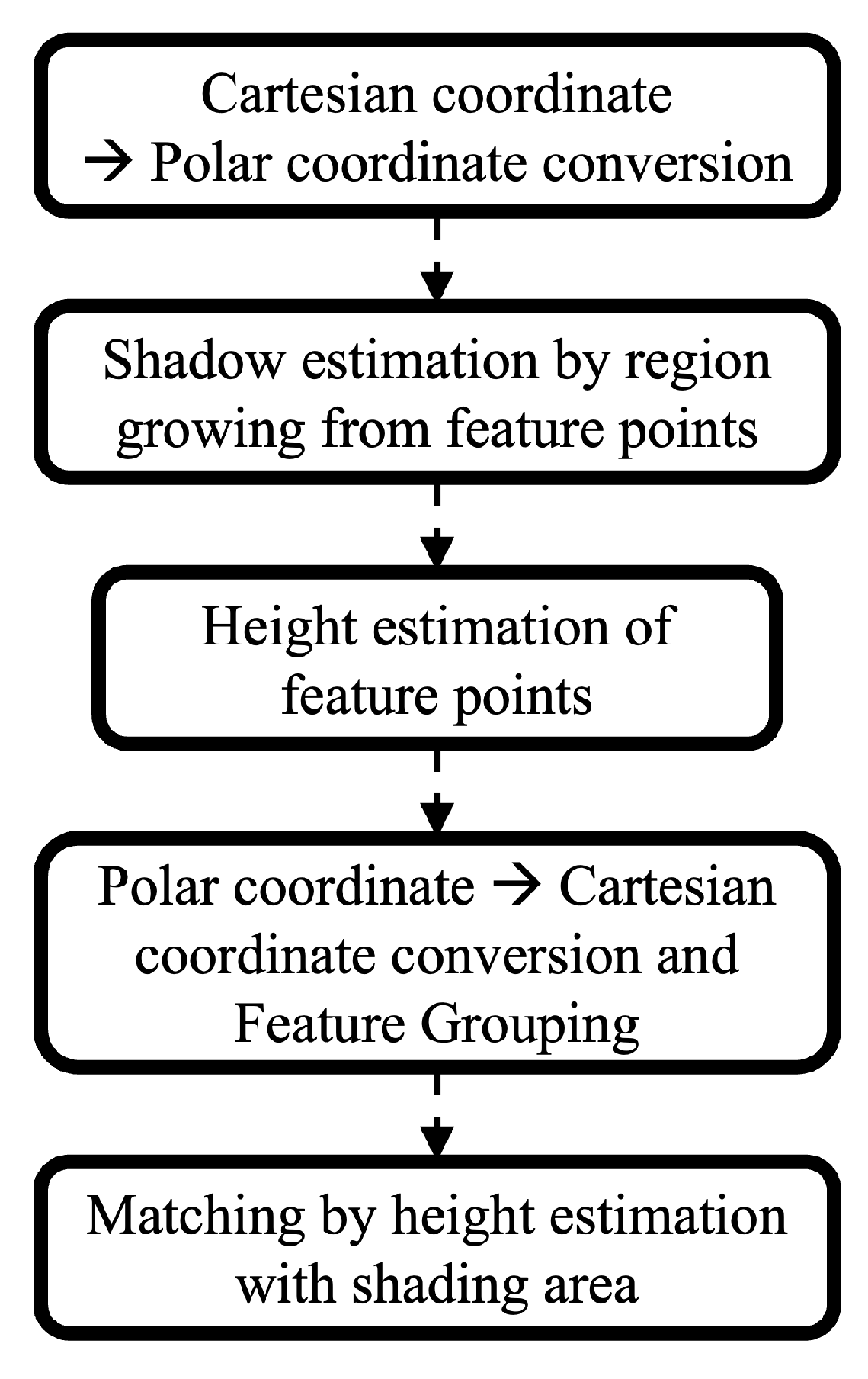
The proposed algorithm is illustrated in Figure 6. This algorithm is categorized into two primary methodologies: matching through the shaded area and matching via the ICP algorithm. Initially, the overlapping region between the two sonar images is estimated using navigation information. Subsequently, matching is executed based on the height estimation derived from the shaded area within the overlapping region. This initial matching result is then utilized to refine the estimation of the overlapping region between the two sonar images, which is followed by an additional matching process employing the ICP algorithm. Refer to Figure 7 and Figure 8 for a comprehensive overview of each method. Detailed discussions are located in Section 3.2 and Section 3.3.

3.2. Shaded Area Estimation and Matching

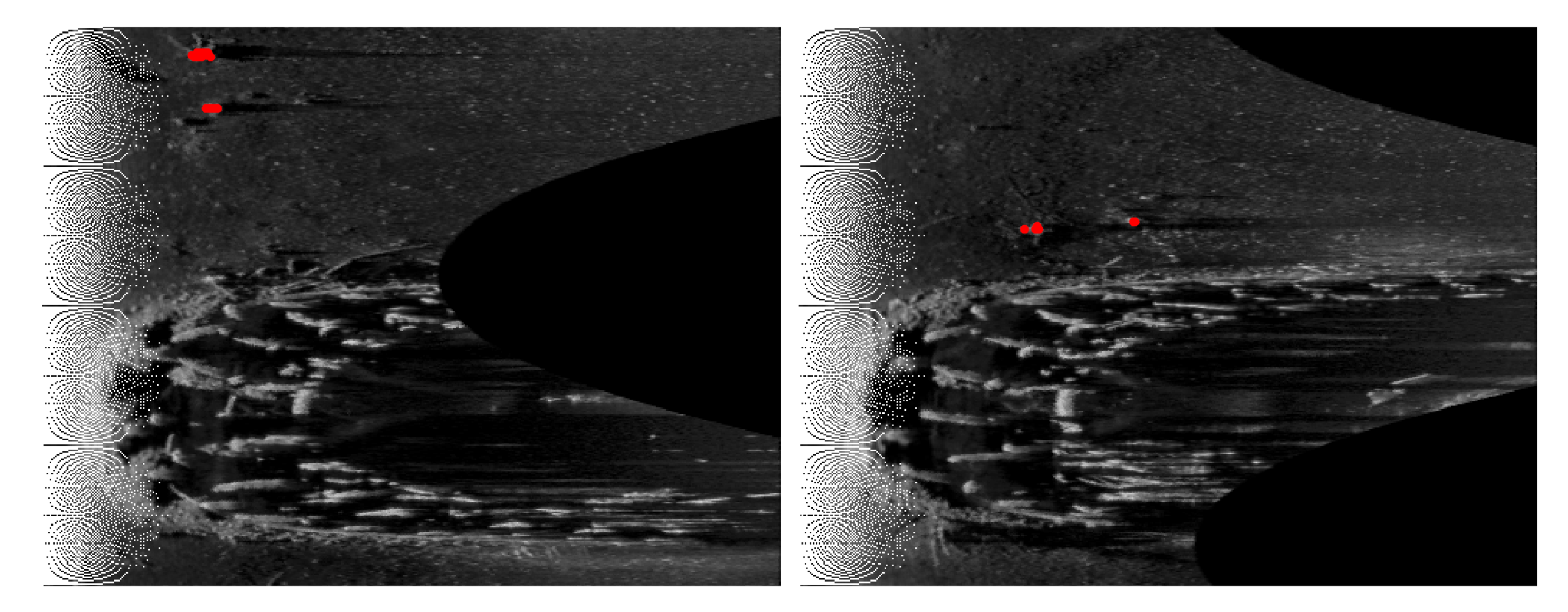
The estimation of shaded areas in sonar imagery is more effectively conducted within a cylindrical coordinate system than within a Cartesian coordinate system, primarily owing to the inherent characteristics of sonar systems. When the data captured by the sensor are represented in a cylindrical coordinate system, such as that used by BlueView, the estimation of shaded areas can proceed without necessitating any conversion between coordinate systems. Conversely, when images are obtained in a Cartesian coordinate system (x, y), such as with scanning sonar data, conversion to a cylindrical coordinate system (r, θ ) is required, as expressed in Equation (1). This study focuses on estimating the height information corresponding to specific feature points, rendering the estimation of all shaded areas in the image unnecessary. Therefore, the estimation process is streamlined by searching in the direction of increasing r at a constant θ . This approach utilizes previously identified feature points, as documented in a prior study [21], as seed points, as depicted in Figure 9a. The search expands in the θ direction ± 1 relative to each seed point. The shaded area is estimated by averaging the sliding window over a 15-pixel range to account for noise and other factors. When the search progresses in the direction of increasing r and encounters another seed point prior to reaching the shaded area, it will continue to move rightward. However, as illustrated in Figure 9b, if a seed point is detected after surpassing the shaded area during this rightward movement, the estimation of the shaded area associated with that seed point is terminated. This occurrence suggests that the shaded area is obscured by another object, thereby making it difficult to accurately estimate its length.
r = x 2 + y 2 , θ = atan 2 ( y , x )
The estimated length of the shaded area is then utilized to compute the height of the corresponding feature point (object), as outlined in Equation (2) and Figure 10. The data related to the feature point, along with the estimated height, are subsequently transformed back into the Cartesian coordinate system to validate the height of the feature point within that framework. The height of a feature point can be estimated at various elevations, even for the same object, owing to the influence of noise. To address this variability, the density-based spatial clustering of applications with noise (DBSCAN) algorithm [32] is employed for the classification of feature points.
x s h o = x o + x s h c , h o = h c x s x o + x s
The resulting classified feature points are then processed in batches to extract the maximum height data from each designated group. The vector ( v l ) and the relationship between the classified feature points in each image data point are determined, followed by evaluating the amount of translation ( T ) and rotation ( θ ). In Equation (3), the letters a and b represent the set of images (denoted by l), and the numeric letters 1 and 2 represent the order in which the groups of classified feature points are listed in order of height (denoted by i). Equation (3) describes the process of calculating the vector ( v l ) that exists between groups of classified features within each image dataset. Subsequently, Equation (4) quantifies the rotation required between the vectors derived from the two image datasets, whereas Equation (5) establishes the rotational direction. The variable θ obtained in this context signifies the extent of rotation necessary to align the two images effectively. Following the rotation of the features from the target image across the two image datasets, as governed by Equation (6), the translation vector ( T ) is computed by averaging the discrepancies observed in the features of the reference image, as articulated in Equation (7).
v l = x l 2 x l 1 y l 2 y l 1 ( l = a , b )
θ = tan 1 v a × v b v a · v b
if det v a v b < 0 , θ = θ
x a i y a i = cos ( θ ) sin ( θ ) sin ( θ ) cos ( θ ) x a i y a i ( i = 1 , 2 , )
T = 1 n i = 1 n x b i x a i

3.3. Proposed Algorithm Obtained by Fusing Two Algorithms

A comprehensive overview of the algorithm proposed herein is discussed in Section 3.1 and visually represented in Figure 6. In this section, we propose an innovative integration of the conventional ICP matching algorithm with a height estimation-based matching approach derived from the shaded area, as detailed in Section 3.2.
The calculation of the overlapping region involves a systematic approach detailed in the following steps. Initially, the images are aligned by applying the translation and rotation parameters determined through navigation and a matching algorithm, which utilize height information inferred from the shaded area. Following this alignment, the points O x n , O y n ( n = a , b ) , which signify the intersection of the edges of the two images, and the points I x n , I y n ( n = a , b ) , representing the deepest encroachments within the overlap, are identified. This identification is achieved through a series of computations outlined in Equations (8)–(14). In the subsequent step, to accurately estimate the overlapping regions derived from the matched images, the four identified points must be transformed into the coordinate system of each respective image. The estimation of the overlapping region is accomplished by calculating a straight line that connects the two intersection points, determining the area enclosed by the three identified points, and examining the area that is symmetrical about this straight line within each original image. In this context, r denotes the radius of each image, while C x n , C y n ( n = a , b ) represent the center coordinates of images a and b, respectively. The steps are as follows:
  • Determine the distance d between the centroids of the two images.
    d = ( C x b C x a ) 2 + ( C y b C y a ) 2
  • Derive the center coordinates C x a b , C y a b between the centroids of the two images.
    C x a b C y a b = C x a C y a + 1 2 C x b C x a C y b C y a
  • Locate O x n , O y n through the distance h between the center coordinates C x a b , C y a b and O x n , O y n .
    h = r 2 ( d / 2 ) 2
    O x n O y n = C x a b C y a b + ± h h × 1 d C y b C y a C x a C x b
  • Determine the angles θ a , θ b between the center and the center coordinates C x a b , C y a b based on the centroid of each image, and thereafter, locate I x n , I y n .
    θ a = atan 2 ( C y b C y a , C x b C x a )
    θ b = atan 2 ( C y a C y b , C x a C x b )
    I x n I y n = C x n C y n + r × cos ( θ n ) sin ( θ n )
Upon estimating the position and orientation via the navigation algorithm, the next step involves identifying the overlapping region. When the heights of two or more feature points (objects) can be accurately estimated from the shaded area within this estimated overlapping region, matching is performed according to the methodology outlined in Section 3.2. Subsequently, the estimated translation and rotation values are employed to reassess the overlapping regions. Following this, an ICP-based matching approach is executed on these overlapping regions. In instances where the height of the feature points (objects) within the initial overlapping region cannot be determined, or if the number of estimated feature points falls below a predetermined minimum threshold, the matching procedure described in Section 3.2 becomes inapplicable. Therefore, an ICP-based matching approach is utilized to facilitate the alignment process.

4. Experiments

The experiments were conducted in two distinct phases. The initial phase utilized basin data to validate the methodology outlined in Section 3.2, wherein the shaded area was employed to estimate the heights of feature points (objects) for matching. The subsequent phase involved real sea data to assess the efficacy of the fusion algorithm proposed in Section 3.3.

4.1. Basin Experiments

4.1.1. Experimental Environment

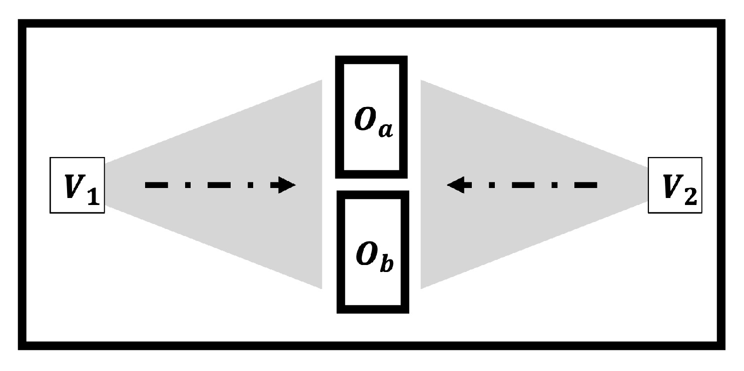
To evaluate the method for estimating object height through shaded area analysis, a series of objects with identical cross-sections but varying heights were strategically placed in the basin, as illustrated in Figure 11a. Images were captured using the BlueView sensor, which is depicted in Figure 2b. The experimental setup required the objects to be securely affixed to the exterior of a plastic box, as shown in Figure 11b, thereby facilitating effective sonar image acquisition. The dimensions of the objects employed in this experiment were as follows: Object A ( O a ) measured 520 mm × 360 mm × 200 mm, while Object B ( O b ) measured 525 mm × 370 mm × 320 mm. Sonar images of these targets were systematically obtained at various orientations and positions, as illustrated in Figure 12. The water depth of the tank was maintained at approximately 2.5 m, and the heights of the objects utilized in the experiment were 0.2 m and 0.32 m, respectively. Owing to the difficulty in distinguishing between the bottom of the tank and the object using the existing algorithm—because the objects were not positioned adequately high enough from the bottom surface due to the shallow water environment—the experiment was conducted after distinguishing the range of the object with visual detection, i.e., specifying a seed point to estimate the object height using its shadow.

4.1.2. Experimental Results

As illustrated in Figure 13, the features are located in the central square-shaped bright area, which is followed by a darker region above it. Notably, the length of the dark area varies depending on the height of the object. When feature extraction relies solely on brightness information, the two images appear to have been captured from a comparable orientation and position. This observation suggests potential inaccuracies in the matching process. The height of the two feature points in Figure 13 can be calculated using Equation (2). However, since h c is not directly measured in this study and the objective is to determine the height ratio between the feature points rather than their absolute heights, the height ratios are compared using Equation (2). The results indicate that the height ratio between the taller and shorter objects at the two feature points is 1.68:1 in Figure 13a and 1.74:1 in Figure 13b, demonstrating a consistent ratio. Therefore, it becomes essential to estimate the height of an object based on the length of the shaded area, as outlined in Section 3.2. By leveraging height information for matching, one can achieve results akin to those depicted in Figure 14b. Conversely, if matching is conducted using only brightness data, the outcome will resemble that shown in Figure 14a. A qualitative assessment of the results reveals that Figure 14b accurately reflects the pose and position of the actual data acquisition, whereas Figure 14a presents an erroneous representation. The sensors in V 1 and V 2 are oriented approximately 180° apart, though installation errors may be present. Using the existing method, the alignment results show a difference of 10.2° in Figure 14a and 178.3° in Figure 14b.

4.2. Real Sea Experiments

4.2.1. Experimental Environment

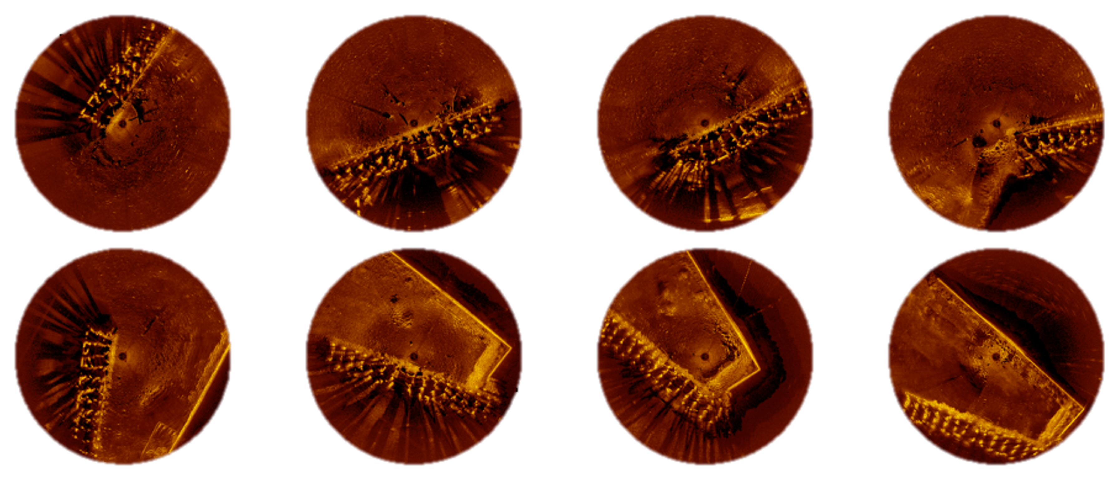
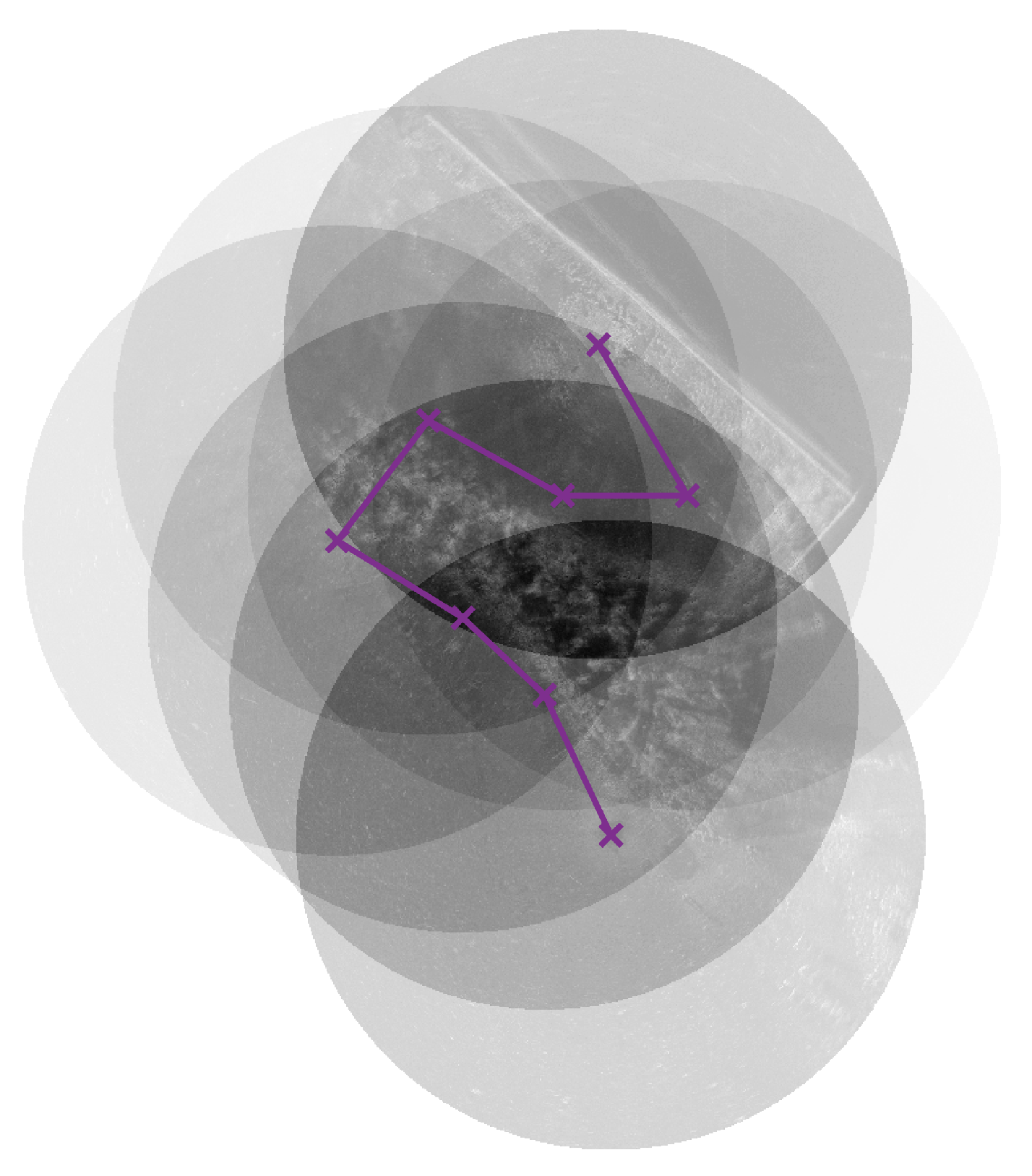
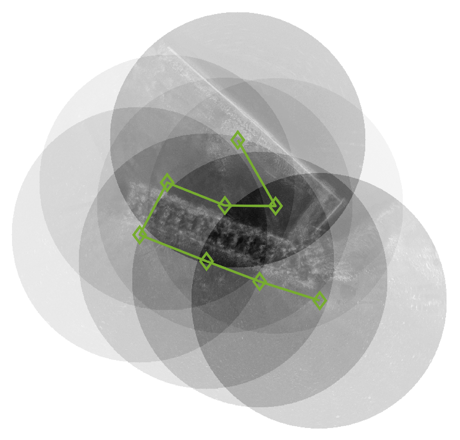
This study utilized eight scanning sonar images, as demonstrated in Figure 15. The images were obtained using the Kongsberg 1171 high-resolution scanning sonar model, with each image resulting from a 50 m radius exploration. The operational specifications and experimental conditions adhered to the methodologies established in prior research [18,19,20,21]. For the scanning sonar images used herein, navigational information was not available during the acquisition process; therefore, the navigational information was estimated backward to test the proposed method of estimating the overlapping region between images. Eight images were visually aligned, and the resulting translational and rotational adjustments were established as the ground truth. To account for navigation errors, a margin of ± 10 % was incorporated into the ground truth, which was then utilized as navigation data. The images aligned according to the ground truth are illustrated in Figure 16.

4.2.2. Experimental Results

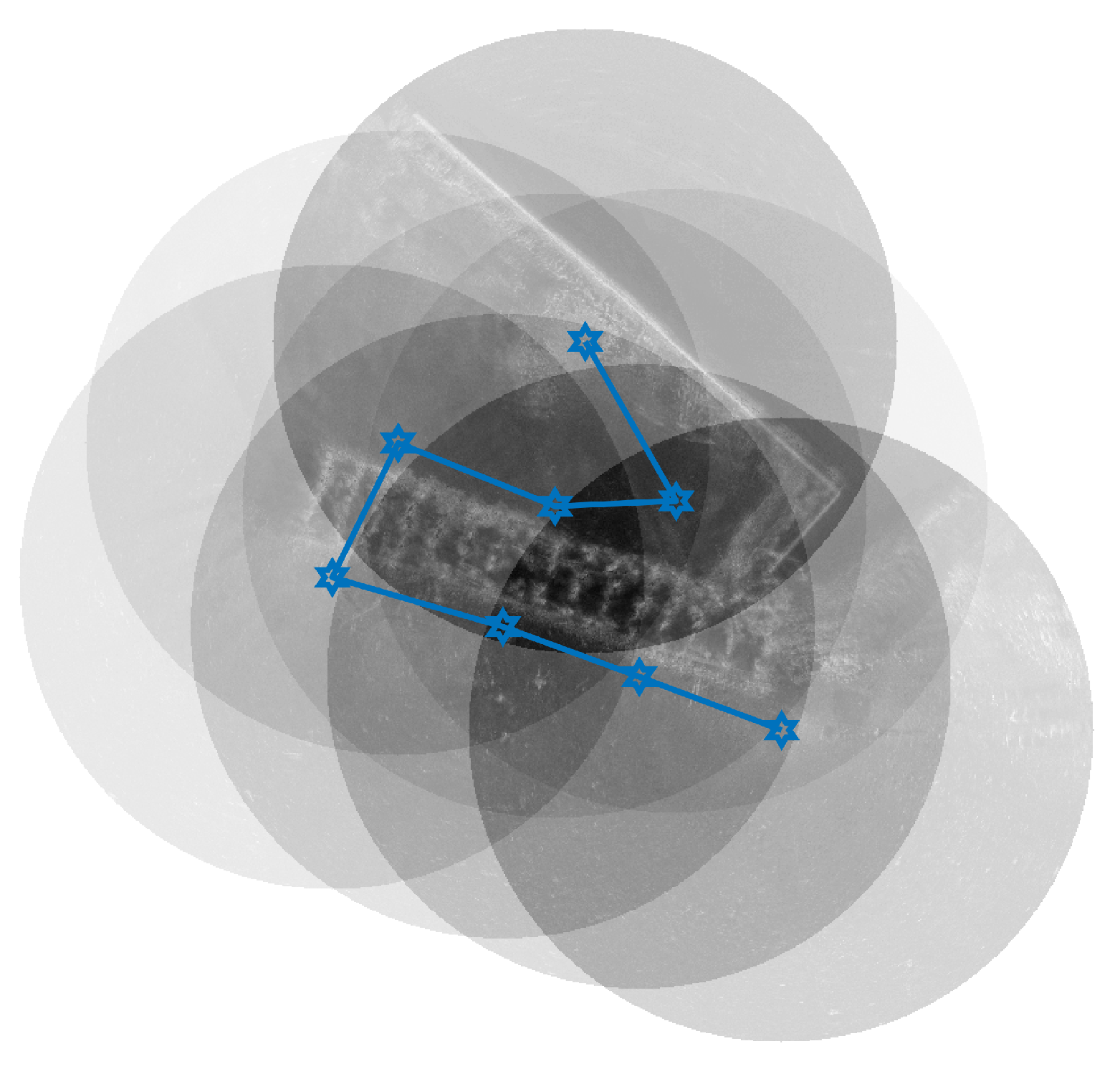
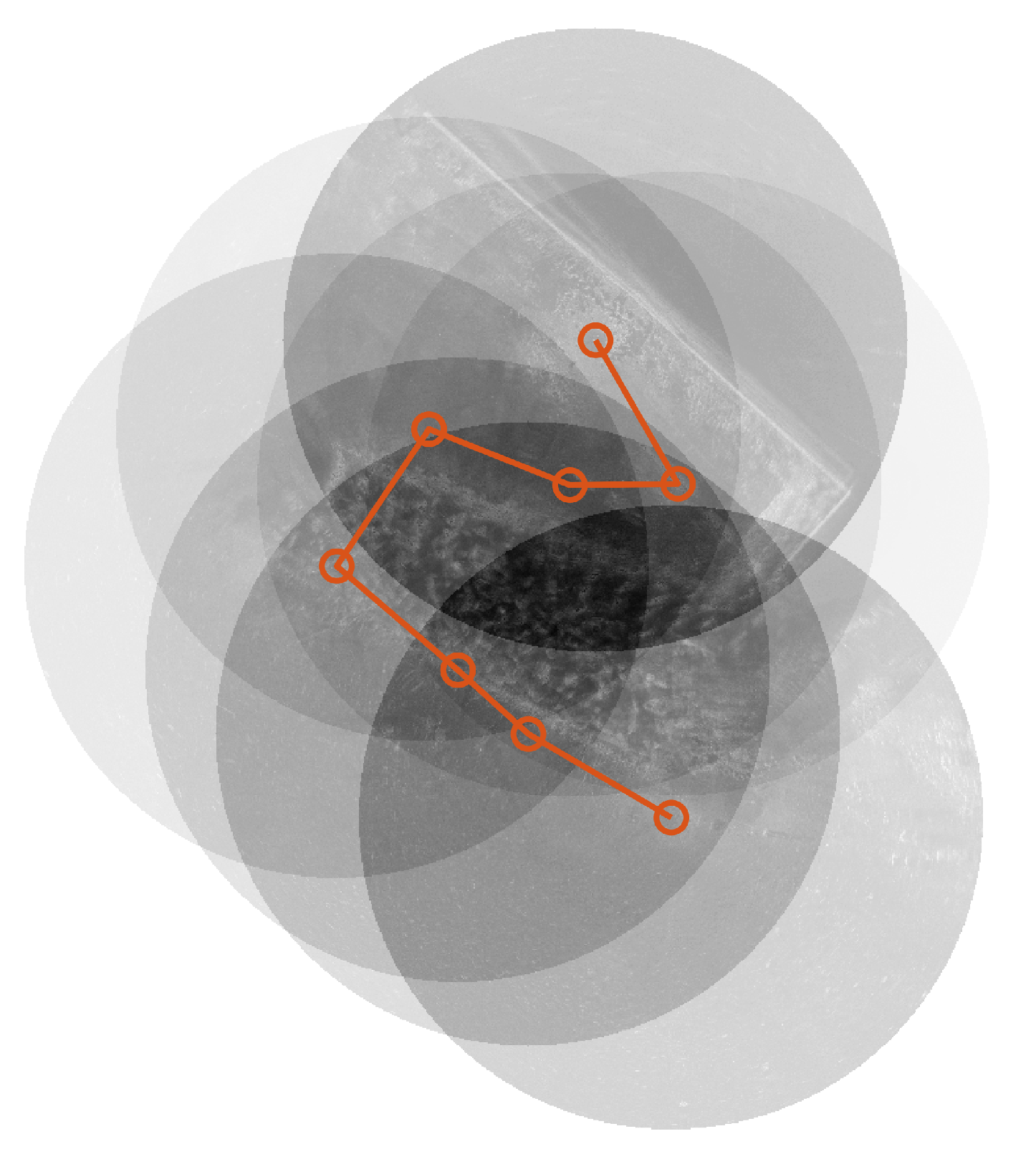
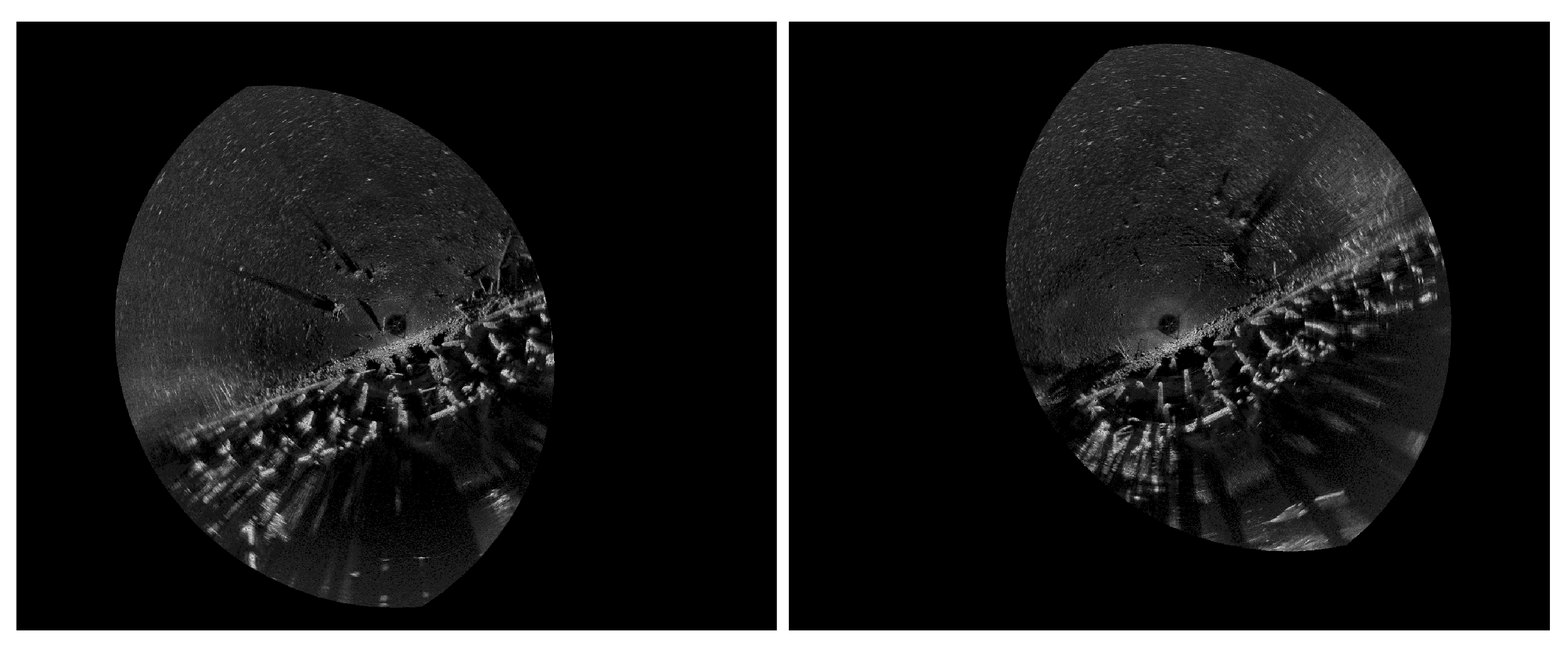
To assess the performance and validity of the proposed method, a series of experiments were carried out. These experiments leveraged the navigation data (with errors incorporated as outlined in Section 4.2.1) and the outcomes were compared against two prior studies [20,21], alongside an innovative algorithm that synergizes the feature point (object) height-based matching approach proposed in this research with the traditional ICP matching algorithm. The image matching process was executed based on the translational and rotational transformations derived from the four methodologies. The results of these matches are presented in Figure 17, Figure 18, Figure 19 and Figure 20. Specifically, Figure 17 showcases the results utilizing the navigation information, Figure 18 illustrates the matching outcome from the previous ICP-based study [21], Figure 19 features results from another prior study employing topological descriptors [20], and Figure 20 highlights the results from the proposed matching approach. In the case of Figure 21, a graph that connects the center points of each sonar image is presented, enabling a visual comparison of the results from each method. Furthermore, Table 1 provides a comprehensive summary of the final positional estimates calculated by each method in comparison to the ground truth established in Section 3. Figure 21 and Table 1 presented herein serve to enhance the comparison and analysis of the ground truth data. Specifically, Figure 22, Figure 23 and Figure 24 depict the stages corresponding to the section outlined in Figure 7 of the proposed algorithm. Figure 22 demonstrates the process of estimating the height of feature points using the region growing method within a cylindrical coordinate system. Following this, Figure 23 presents the results of transforming the estimated feature heights into a Cartesian coordinate system. The calculated height ratio results show that the ratios between A and B are 1.7:1 and 1.8:1 in the two respective images. Using this information, the matching process and overlapping region estimation results are visualized in Figure 24. The subsequent steps of the algorithm are performed in the same manner as in previous studies [21]. In terms of qualitative evaluation, as illustrated in Figure 18 and Figure 19, it is evident that both the ICP algorithm-based matching and the topology descriptor-based matching exhibit notable inaccuracies when attempting to align features that are similar in size and arrangement. Conversely, the proposed method allows for a more precise estimation of the overlapping region, achieved by re-evaluating this area based on the height estimation of a point, as indicated by the shaded area in the figures. Additionally, matching results utilizing the ICP approach show improved accuracy when this method is applied. This underscores the critical importance of accurately estimating the overlapping region prior to the matching process. It further suggests that the overlapping region can be quantified with greater precision by evaluating the heights of feature points, leveraging the information provided by the shaded area. For the quantitative assessment, all eight images were subjected to matching across each of the four experimental methodologies. The evaluation was conducted by comparing the centroid position of the final image against the ground truth, relative to the centroid of the initial image. The analysis of the values reveals significant discrepancies in alignment accuracy across various methods. Specifically, the error margins are as follows: 227 pixels (equivalent to 23.97 m) when utilizing navigation information, 147 pixels (12.53 m) with the ICP algorithm, 316 pixels (33.29 m) for topology descriptor-based alignment, and a notably reduced error of just 8 pixels (0.89 m) when employing the proposed method. The enhancements in performance by employing the proposed method are remarkable, yielding improvements of 96.48%, 94.56%, and 97.47% compared to the respective baseline methods. Both qualitative and quantitative analyses substantiate that the proposed method achieves superior matching accuracy relative to the comparative techniques. Specifically, the proposed approach leverages the height information of feature points obtained from shaded areas to estimate overlapping regions more accurately, rather than relying solely on navigation data. This enhanced estimation of overlapping regions contributes to the significant improvement in matching performance achieved by the proposed method.

5. Discussion

This research introduces a novel sonar image registration algorithm that combines navigation data with 3D feature height estimation to overcome the limitations of conventional methods. To validate the effectiveness of the proposed approach, a series of experiments were conducted, including tests with real-world sonar data. The results demonstrate that the algorithm achieves superior matching accuracy, significantly reducing errors compared to existing techniques. The scanning sonar system utilized herein is characterized by an extended data acquisition duration, which complicates the collection of data while in motion. Furthermore, current ICP-based matching algorithms, which rely on two-dimensional scanning sonar data, often produce inaccuracies when confronted with features that share similar dimensions and configurations. To mitigate these challenges, this study proposes a dual-faceted approach for estimating overlapping regions from continuous sonar data. The first strategy leverages position and orientation data derived from the navigation algorithm to assist in the estimation process. The second strategy incorporates the shaded regions of the scanning sonar image to ascertain the height of feature points based on three-dimensional data. This dual approach enhances the accuracy of overlapping region calculations, ultimately improving the alignment of sonar images. The proposed algorithm was rigorously evaluated through simulations, which indicated that the length of the shaded area fluctuated based on the height of the feature under consideration. Additionally, the method for height estimation that leverages the shaded area underwent validation in a controlled basin experiment. The robustness of the algorithm was further substantiated by correlating sonar data collected from various positions and orientations. Subsequently, the method was applied to eight real-world scanning sonar images captured in marine environments to facilitate alignment. The effectiveness of the proposed approach was assessed by contrasting the alignment outcomes derived solely from navigation information against those obtained through a combination of navigation data and the ICP algorithm, as well as alignment results that integrated navigation information with topology descriptors. The performance was assessed by analyzing the centroid position error of the final images, which demonstrated that the proposed method exhibited commendable performance, especially for image pairs possessing three-dimensional data. This study aims to enhance the functionality of the ICP algorithm by accurately estimating overlapping regions between sonar images. However, if the accurate estimation of overlapping regions does not result in correct alignment, as indicated by errors derived from the ICP process or inconsistencies with navigation data, future research will explore methods to estimate overlapping regions using previously aligned images. This approach will involve aligning newly acquired images with already registered ones. Furthermore, if alignment remains unsuccessful under these conditions, advanced navigation data from inertial navigation systems and USBL will be employed to develop a more sophisticated image registration method. To further refine the practical application of the proposed method, considerations regarding computational efficiency are crucial. The majority of the computational time in the proposed algorithm is attributed to the coordinate transformation process, while the remaining operations are performed using the real-time capable ICP algorithm and other computationally efficient methods. To facilitate the implementation of the proposed method on actual hardware, optimization of the algorithm is essential. The equipment currently under development is equipped with a GPU (Graphic Processing Unit) that supports multi-threaded parallel processing, and an optimization process tailored to leverage this capability is planned.

Author Contributions

G.L., J.L. and S.Y. designed the concept and methodology; G.L. and J.L. performed data analysis; G.L. developed the software, conducted the basin experiments, and wrote the draft of the manuscript. J.L. reviewed and edited the manuscript. Y.L. set up and located the basin experiment. All authors have read and agreed to the published version of the manuscript.

Funding

This work was supported by Korea Research Institute for Defense Technology Planning and Advancement (KRIT)—grant funded by Defense Acquisition Program Administration (DAPA) (KRIT-CT-22-066).

Institutional Review Board Statement

Not applicable.

Informed Consent Statement

Not applicable.

Data Availability Statement

Data are contained within the article.

Acknowledgments

The scanning sonar and BlueView data used in this paper were provided by KRISO (KOREA RESEARCH INSTITUTE OF SHIPS and OCEAN ENGINEERING).

Conflicts of Interest

Author Sukmin Yoon was employed by the company Hanwha System. The remaining authors declare that the research was conducted in the absence of any commercial or financial relationships that could be construed as a potential conflict of interest.

References

  1. Li, J.-H. Study on the UUV Operation via Conventional Submarine’s Torpedo Tube. J. Korea Inst. Mil. Sci. Technol. 2024, 17, 33–40. [Google Scholar] [CrossRef]
  2. Ko, E.S.; Lee, M.H. A Study on the Legal Status of Unmanned Maritime Systems. Korean J. Mil. Art Sci. 2019, 75, 89–118. [Google Scholar]
  3. Lee, K.Y. An analysis of required technologies for developing unmanned mine countermeasure system based on the unmanned underwater vehicle. J. Korea Inst. Mil. Sci. Technol. 2011, 14, 579–589. [Google Scholar] [CrossRef]
  4. Byun, S.-W.; Kim, D.; Im, J.-B.; Han, J.-H.; Park, D.-H. A Study on Guidance Methods of Mine Disposal Vehicle Considering the Sensor Errors. J. Embed. Syst. Appl. 2017, 12, 277–286. [Google Scholar]
  5. Kim, K.; Choi, H.-T.; Lee, C.-M. Multi-sensor Fusion Based Guidance and Navigation System Design of Autonomous Mine Disposal System Using Finite State Machine. Inst. Electron. Eng. Korea Syst. Control 2010, 47, 33–42. [Google Scholar]
  6. Yoo, S.Y.; Jun, B.H.; Shim, H. Design of Static Gait Algorithm for Hexapod Subsea Walking Robot: Crabster. Trans. Korean Soc. Mech. Eng. A 2014, 38, 989–997. [Google Scholar] [CrossRef]
  7. Jun, B.-H.; Yoo, S.-Y.; Lee, P.-M.; Park, J.-Y.; Shim, H.; Baek, H. The sea Trial of Deep-sea Crabster CR6000 System. J. Embed. Syst. Appl. 2017, 12, 331–341. [Google Scholar]
  8. Park, J.-Y.; Lee, G.-M.; Shim, H.; Baek, H.; Lee, P.-M.; Jun, B.-H.; Kim, J.-Y. Head Alignment of a Single-beam Scanning SONAR installed on a Multi-legged Underwater Robot. In Proceedings of the 2012 Oceans, Hampton Roads, VA, USA, 14–19 October 2012; pp. 1–5. [Google Scholar]
  9. Baek, H.; Jun, B.-H.; Park, J.Y.; Kim, B.R.; Lee, P.M. Application of High Resolution Scanning Sonar with Multi-Legged Underwater Robot. In Proceedings of the 2013 OCEANS, San Diego, CA, USA, 23–27 September 2013; pp. 1–5. [Google Scholar]
  10. Jun, B.-H.; Shim, H.; Park, J.-Y.; Kim, B.; Lee, P.-M. A new concept and technologies of multi-legged underwater robot for high tidal current environment. In Proceedings of the 2011 IEEE Symposium on Underwater Technology and Workshop on Scientific Use of Submarine Cables and Related Technologies, Tokyo, Japan, 5–8 April 2011; pp. 1–5. [Google Scholar]
  11. Yoo, S.-Y.; Jun, B.-H.; Shim, H.; Shim, P.-M. Finite Element Analysis of Carbon Fiber Reinforced Plastic Frame for Multi-legged Subsea Robot. J. Ocean. Eng. Technol. 2013, 27, 65–72. [Google Scholar] [CrossRef]
  12. Lee, G.; Choi, K.; Lee, P.-Y.; Kim, H.S.; Lee, H.; Kang, H.; Lee, J. Performance Enhancement Technique for Position-based Alignment Algorithm in AUV’s Navigation. J. Inst. Control. Robot. Syst. 2023, 29, 740–747. [Google Scholar] [CrossRef]
  13. Ma, J.; Yu, Y.; Zhang, Y.; Zhu, X. An USBL/DR Integrated Underwater Localization Algorithm Considering Variations of Measurement Noise Covariance. IEEE Access 2022, 10, 23873–23884. [Google Scholar] [CrossRef]
  14. Guerrero-Font, E.; Massot-Campos, M.; Negre, P.L.; Bonin-Font, F.; Codina, G.O. An USBL-aided multisensor navigation system for field AUVs. In Proceedings of the 2016 IEEE International Conference on Multisensor Fusion and Integration for Intelligent Systems (MFI), Baden-Baden, Germany, 19–21 September 2016; pp. 430–435. [Google Scholar]
  15. Ribas, D.; Ridao, P.; Mallios, A.; Palomeras, N. Delayed state information filter for USBL-Aided AUV navigation. In Proceedings of the 2012 IEEE International Conference on Robotics and Automation, Saint Paul, MN, USA, 14–18 May 2012; pp. 430–435. [Google Scholar]
  16. Davis, A.; Lugsdin, A. High speed underwater inspection for port and harbour security using Coda Echoscope 3D sonar. In Proceedings of the OCEANS 2005 MTS/IEEE, Washington, DC, USA, 17–23 September 2005; pp. 2006–2011. [Google Scholar]
  17. Woodward, W.R.; Webb, P.E.R.; Hansen, R.K.; Cunningham, B.; Markiel, J.N. Approaches for using Three Dimensional sonar as a supplemental sensor to GNSS. In Proceedings of the IEEE/ION Position, Location and Navigation Symposium, Indian Wells, CA, USA, 4–6 May 2010; pp. 1112–1117. [Google Scholar]
  18. Baek, H.; Jun, B.H.; Noh, M.D. The application of sector-scanning sonar: Strategy for efficient and precise sector-scanning using freedom of underwater walking robot in shallow water. Sensors 2020, 20, 3654. [Google Scholar] [CrossRef] [PubMed]
  19. Baek, H.; Jun, B.H.; Park, J.-Y.; Shim, H.; Lee, P.-M.; Noh, M.D. 2D and 3D Mapping of Underwater Substructure Using Scanning SONAR System. J. KNST 2019, 2, 21–27. [Google Scholar] [CrossRef]
  20. Choi, K.; Lee, G.; Lee, P.-Y.; Yoon, S.-M.; Son, J.; Lee, J. Optimal Parameter Estimation for Topological Descriptor Based Sonar Image Matching in Autonomous Underwater Robots. J. Inst. Control Robot. Syst. 2024, 30, 730–739. [Google Scholar] [CrossRef]
  21. Lee, G.; Choi, K.; Lee, P.-Y.; Yoon, S.-M.; Son, J.; Lee, J. Scanning-sonar Image Matching Algorithm Using Overlapping Region Detection and ICP. J. Inst. Control. Robot. Syst. 2024, 30, 226–233. [Google Scholar] [CrossRef]
  22. Cotter, E.; Polagye, B. Detection and classification capabilities of two multibeam sonars. Limnol. Oceanogr. Methods 2020, 18, 673–680. [Google Scholar] [CrossRef]
  23. Franchi, M.; Ridolfi, A.; Zacchini, L. A forward-looking sonar-based system for underwater mosaicing and acoustic odometry. In Proceedings of the 2018 IEEE/OES Autonomous Underwater Vehicle Workshop (AUV), Porto, Portugal, 6–9 November 2018; pp. 1–6. [Google Scholar]
  24. Douillard, B.; Underwood, J.; Kuntz, N.; Vlaskine, V.; Quadros, A.; Morton, P.; Frenkel, A. On the segmentation of 3D LIDAR point clouds. In Proceedings of the 2011 IEEE International Conference on Robotics and Automation, Shanghai, China, 9–13 May 2011; pp. 2798–2805. [Google Scholar]
  25. Aykin, M.D.; Negahdaripour, S. Forward-look 2-D sonar image formation and 3-D reconstruction. In Proceedings of the 2013 OCEANS, San Diego, CA, USA, 23–27 September 2013; pp. 1–10. [Google Scholar]
  26. Joe, H.; Kim, J.; Yu, S.C. 3D reconstruction using two sonar devices in a Monte-Carlo approach for AUV application. Int. J. Control. Autom. Syst. 2020, 18, 587–596. [Google Scholar] [CrossRef]
  27. Sung, M.; Kim, J.; Cho, H.; Lee, M.; Yu, S.-C. Underwater-Sonar-Image-Based 3D Point Cloud Reconstruction for High Data Utilization and Object Classification Using a Neural Network. Electronics 2020, 9, 1763. [Google Scholar] [CrossRef]
  28. Joe, H.; Kim, J.; Yu, S.-C. Probabilistic 3D Reconstruction Using Two Sonar Devices. Sensors 2022, 22, 2094. [Google Scholar] [CrossRef] [PubMed]
  29. Lee, Y.; Kim, T.; Choi, J.; Choi, H.-T. Experimental Results on Shape Reconstruction of Underwater Object Using Imaging Sonar. J. Inst. Electron. Inf. Eng. 2016, 53, 116–122. [Google Scholar] [CrossRef]
  30. Manhães, M.M.M.; Scherer, S.A.; Voss, M.; Douat, L.R.; Rauschenbach, T. UUV Simulator: A Gazebo-based package for underwater intervention and multi-robot simulation. In Proceedings of the OCEANS 2016 MTS/IEEE Monterey, Monterey, CA, USA, 19–23 September 2016; pp. 1–8. [Google Scholar]
  31. Lee, G.; Choi, K.; Yoon, S.-M.; Lee, J. UUV Simulator: Image Registration of 2D Underwater Sonar Images Using Shadow-based Height Estimation. In Proceedings of the The Institute of Electronics and Information Engineers Summer Annual Conterence of IEIE, Jeju, Republic of Korea, 27–29 February 2024; pp. 1415–1418. [Google Scholar]
  32. Ester, M.; Kriegel, H.P.; Sander, J.; Xu, X. A density-based algorithm for discovering clusters in large spatial databases with noise. In Proceedings of the Second International Conference on Knowledge Discovery and Data Mining, KDD’96, Portland, OR, USA, 2–4 August 1996; pp. 226–231. [Google Scholar]
Figure 1. Multi-legged seabed walking robot—Crabster.
Jmse 13 00150 g001
Figure 2. Sonar used in this study: (a) “Scanning Sonar” and (b) “BlueView”.
Jmse 13 00150 g002
Figure 3. Characteristic of sonar: Objects at different elevations but perceived as a single object due to alignment along the same bearing and distance.
Jmse 13 00150 g003
Figure 4. Characteristic of sonar: Shaded area caused by an object blocking ultrasound, with possible uncertainty about lower objects.
Jmse 13 00150 g004
Figure 5. (a) Cylinders of varying heights used for sonar imaging. (b) Sonar results displaying shaded area lengths varying with object height and sensor distance. (c) Converted cylindrical coordinates with continuous shaded areas along increasing r at constant θ .
Jmse 13 00150 g005
Figure 6. Overview of the proposed algorithm.
Jmse 13 00150 g006
Figure 7. Overall overview of the matching method by height estimation with the shaded area.
Jmse 13 00150 g007
Figure 8. Overall overview of matching method using the ICP algorithm.
Jmse 13 00150 g008
Figure 9. (a) Shaded area estimation using seed points, expanding in the direction of increasing r. (b) Estimation interrupted owing to occlusion by another object.
Jmse 13 00150 g009
Figure 10. Estimation of the object’s height based on the measured length of the shaded area.
Jmse 13 00150 g010
Figure 11. (a) Objects placed in a basin for height estimation. (b) Plastic box cemented to aid in sonar image acquisition.
Jmse 13 00150 g011
Figure 12. Sonar images obtained from two viewpoints V 1 and V 2 in the basin.
Jmse 13 00150 g012
Figure 13. Sonar images obtained from two viewpoints V 1 and V 2 in the basin ((a): V 1 ; (b): V 2 ).
Jmse 13 00150 g013
Figure 14. Matching result: (a) Using intensity information; (b) using height information.
Jmse 13 00150 g014
Figure 15. Eight scanning sonar images acquired using Kongsberg’s 1171 high-resolution scanning sonar with a 50 m exploration radius.
Jmse 13 00150 g015
Figure 16. Ground truth derived from visually matching eight scanning sonar images.
Jmse 13 00150 g016
Figure 17. Matching results using navigation information.
Jmse 13 00150 g017
Figure 18. Matching results using the ICP algorithm from a previous study.
Jmse 13 00150 g018
Figure 19. Matching results using topological descriptors from a previous study.
Jmse 13 00150 g019
Figure 20. Matching results using the proposed method based on height estimation of feature points.
Jmse 13 00150 g020
Figure 21. Matching accuracy of the proposed method compared to other approaches by comparing centroid positions of each image matched by each method.
Jmse 13 00150 g021
Figure 22. Estimation of feature height in the cylindrical coordinate system using the proposed method. Red dot: feature point with estimated height.
Jmse 13 00150 g022
Figure 23. Conversion of estimated feature coordinates and height values from the cylindrical to Cartesian coordinate system. A: Group of points with the highest height, B: Group of points with the lowest height.
Jmse 13 00150 g023
Figure 24. Overlapping region between two sonar images calculated using the proposed method based on height estimation from shadows.
Jmse 13 00150 g024
Table 1. Results of endpoint position errors for each method.
Endpoint Position Error
mPixel
MethodA23.97227
B12.53147
C33.29316
D0.898
A: Using navigation information. B: Using the ICP algorithm from a previous study. C: Using topological descriptors from a previous study. D: Using the proposed method based on height estimation of feature points.
Disclaimer/Publisher’s Note: The statements, opinions and data contained in all publications are solely those of the individual author(s) and contributor(s) and not of MDPI and/or the editor(s). MDPI and/or the editor(s) disclaim responsibility for any injury to people or property resulting from any ideas, methods, instructions or products referred to in the content.