Abstract
The High Voltage Direct Current (HVDC) transmission technology employing modular multilevel converters (MMCs) can effectively enhance the transmission efficiency and stability of offshore wind farms, thereby aiding the promotion of large−scale utilization of new energy. This holds significant importance for achieving the dual carbon goals. Aiming at the problem of negative sequence current circulation in MMC−HVDC transmission systems, a circulation suppression strategy based on augmented order decoupling linear active disturbance rejection control (LADRC) is proposed in this paper. By introducing new state variables into the traditional ADRC structure, the actual output deviation signal and observation gain signal from the disturbance observation value of the system are used. It can not only realize the decoupling control of disturbance and tracking terms but also enhance the disturbance immunity, robustness and rapidity of the controller. Finally, an 18−level MMC system model is built based on Matlab (9.12.0.1884302 (R2022a)) & Simulink (R2022a), and the circulation suppression effects of stable operation and voltage sudden change are simulated and compared, which verifies the suppression effect of the improved control strategy on negative sequence current circulation, which lays a theoretical and application foundation for the sustainable development of the offshore wind power industry.
1. Introduction
Global warming and climate change pose an existential threat to humanity. Pursuing industrial development while vigorously expanding renewables is the core strategy of many countries around the world [1]. Renewable energy has been widely used in various industries because of its low cost, environmental friendliness and other advantages. Among them, offshore wind power, ocean energy and solar power are the main new energy forms in the world [2,3,4]. Offshore wind power has become an important part of the large-scale utilization of new energy because of its rich resource reserves, high power generation efficiency, low water consumption, small land occupation area and close to power load center [5,6]. The development of offshore wind power is helping to build a clean, low-carbon, safe and efficient energy future, in order to meet the challenges of climate change and energy security [7]. With the gradual expansion of the scale of offshore wind farms and the continuous increase of offshore distance, the traditional interconnection of offshore wind farms with the onshore substations by high voltage alternating current cables does not find techno-economic feasibility. Advanced schemes and technologies of submarine power transmission are necessary to facilitate the capacity expansion of offshore wind farms [8,9,10].
In order to improve the large-scale utilization efficiency of offshore new energy and ensure the high quality of electric energy in the process of transmission, key technologies such as wind turbines, floating wind power platforms, submarine cables and power transmission have been launched one after another. Among them, HVDC technology has the characteristics of strong controllability, small footprint and efficient long-distance power transmission. It can effectively transport the power generated by offshore wind power to onshore substation, improve the reliability of power supply, reduce the loss of transmission lines, increase the transmission capacity of transmission lines and provide protection for offshore wind power and other large-scale access [11,12,13,14,15]. Therefore, HVDC technology has become one of the main means of cross-sea large-scale power transportation. It has become a new choice for power supply in mega-cities and isolated islands [16,17], and it is also one of the best choices for large-scale clean energy power generation to be connected and transmitted by high-voltage DC power grids in the future [18,19].
Compared with the HVDC system with its traditional two-level or three-level converter, a modular multilevel converter (MMC) has the characteristics of low switching loss, low harmonic loss and fast response to power grid fluctuations, which can realize the efficient, stable and controllable operation of an HVDC system [20,21,22]. However, due to the structure of MMC itself, the instantaneous voltages of the sub-modules of the upper and lower bridge arms are different, which leads to the internal circulation between the phases in the normal operation of the system. The existence of circulating current not only increases power consumption and energy loss and causes voltage fluctuation and voltage distortion but also shortens the service life of power electronic devices [23,24]. Well-specified circulating current suppressors play an important role in improving power quality, reducing loss and optimizing system performance in HVDC systems. The commonly used circulating current suppressor are divided into passive circulating current suppressors and active circulating current suppressors. Passive circulating current suppressors mainly rely on physical methods to adjust the elements to achieve the suppression of interphase circulation, but the flexibility and adaptability are general. The active circulating current suppressor dynamically suppresses the circulation through the software method; the response speed is fast, it avoids the problems caused by the passive circulating current suppressors and it is the main method to restrain the circulation [25,26]. Therefore, the design of a reasonable and effective circulation suppression strategy is of great significance to promote the progress of HVDC technology and the large-scale expansion of offshore wind power [27,28].
Traditional methods of circulating current suppression often employ Proportional Integral (PI) control [29,30]. However, the decoupling process involved in the control loop leads to increased workload, and the system stability and effectiveness in suppressing circulating currents are limited. Reference [31] introduces the Proportional Resonant (PR) controller, which eliminates coordinate transformations, as well as the coupling terms and feedforward compensation items affected by circuit parameters. In response to issues such as high parameter sensitivity, poor disturbance rejection and narrow bandwidth in PR controllers, literature [32] proposes a quasi-PR controller. However, it incorporates a notch filter to enhance control effectiveness and necessitates stability analysis of the system. Literature [33] combines a low-pass filter with Internal Model Control (IMC) to enhance the robustness of the system. Compared with the above methods, ADRC provides stronger robustness through active interference suppression, has relatively low requirements for dynamic characteristics of the system, and can quickly respond to changes and disturbances of the system [34]. ADRC circulation suppression strategy helps to improve the overall stability of the power system, which plays a key role in preventing system instability, oscillation or even collapse. Reference [35], utilizing the characteristic of LADRC that does not rely on a detailed model of the MMC circulating current, designs a circulating current suppression strategy that simplifies the mechanisms of circulating current control, demonstrating good robustness but constrained by bandwidth limitations. In the literature [36], a circulating current suppressor based on virtual impedance sliding mode control is proposed, and its transient performance is simulated. However, no explicit criteria are provided for evaluating the effectiveness of the circulating current suppressor.
This paper aims at the problem of negative sequence current circulation in long-distance MMC-HVDC in marine environments. Based on the analysis of the working mechanism of MMC bridge arm circuit, an improved LADRC circulation suppression strategy of MMC based on offshore wind power is proposed in this paper. By changing the structure of the linear extended state observer (LESO), a new differential term is introduced into LESO. Augmented Order Decoupling LADRC (AD-LADRC) is designed to increase the bandwidth of the controller and decouple the disturbance term and tracking term of the controller. Through modeling, simulation and comparing the coupling relationship, the rapidity and stability of the ADRC are improved. The parameter setting process is simplified, and the system performance is optimized. The effectiveness of the improved LADRC circulating current suppressor is verified by a Matlab & Simulink simulation, and the circulation suppression effects of stable operation and voltage sudden change are analyzed and compared.
2. Advantages of HVDC Technology
HVDC provides strong technical support for the development and application of offshore wind farms. The offshore wind power HVDC project involved in this paper is shown in Figure 1 [37].
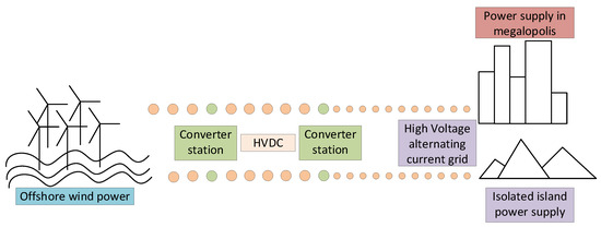
Figure 1.
Overview of Offshore Wind Power HVDC Project.
As can be seen from Figure 1, the converter station is the key equipment of HVDC technology and an important hub connecting offshore wind farms and power loads. By controlling the turn-on and turn-off time of switching devices, the stepless conversion of AC and DC energy between different forms of power grids or between different voltage levels is realized; thus harmonics and losses are reduced.
An LADRC circulation suppression strategy of MMC-HVDC based on offshore wind power proposed in this paper has the following advantages:
- (1)
- The harmonic level is low.
Compared with traditional DC transmission technology, the HVDC system with a modular multilevel converter generates voltage and current close to sinusoidal waveform, which has a significant effect on improving the quality and stability of power transmission in offshore wind farms.
- (2)
- The stability of the system is enhanced.
By reducing the influence of external disturbances, the ADRC circulation suppression strategy helps to improve the overall stability of the offshore wind farm HVDC system. This plays a key role in preventing instability, oscillation or even collapse of the system.
- (3)
- There is no reactive power compensation and no commutation failure.
HVDC technology uses turn−off devices to control the turn-on and turn-off time. This method does not rely on the AC side to provide commutation current and reverse voltage and effectively avoids the loss of a large amount of reactive power. In addition, it has nothing to do with the current direction and fundamentally solves the problem of commutation failure.
- (4)
- It has the ability to supply electricity to isolated islands.
Because HVDC technology can realize commutation independently and can operate in passive inverter mode without external commutation voltage, the receiving end system can be a passive network.
- (5)
- It is suitable for constructing a multi-terminal system.
The current of the HVDC system can flow in both directions, and the polarity of the DC voltage remains unchanged when the power flow is reversed. This makes it suitable for the construction of multi-terminal systems, in which the power flow between converter stations is more flexible, and it can provide a convenient connection form for the follow-up large-scale construction of new energy at sea and the combination of multi-energy situations.
3. Analysis of Working Mechanism of MMC Bridge Arm Circuit
3.1. MMC Topology
The single-phase equivalent circuit model of the Modular Multilevel Converter is depicted in Figure 2 [38].
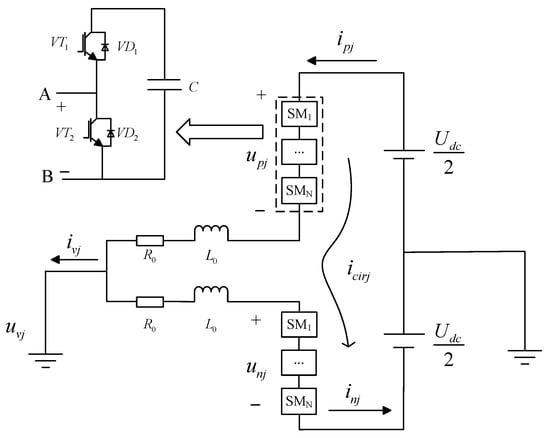
Figure 2.
MMC single-phase equivalent circuit model.
It comprises upper and lower bridge arms, each formed by equivalent resistors, inductors and N sub-modules. The sub-module capacitor voltages are denoted as and ; the bridge arm currents are labeled as and ; the internal circulating current is denoted as . In this context, represents the inductance of the bridge arm, and denotes the resistance of the bridge arm. On the AC side, the single-phase voltage is represented as , and the current is denoted as . On the DC side, the total voltage is denoted as . Each sub-module includes two IGBT switches, labeled as and , Each sub-module includes two anti-parallel diodes, labeled as and , and a capacitor, labeled as .
3.2. Analysis of the Principle of MMC Circulation
Obtained from the MMC single-phase equivalent circuit (1):
In the equation, , represents the internal electromotive force of the three-phase system (abc).
Based on Kirchhoff’s laws, the expression (2) for the reference values of the capacitor voltages in the upper and lower bridge arms can be derived:
In the equation, represents the circulating voltage drop across a single bridge arm.
Define the modulation ratios for MMC output voltage and output current (3):
In the equation, represents the amplitude of the AC side voltage, and denotes the amplitude of the AC side current.
The voltage and current equations for the upper and lower bridge arms are as shown in Equation (4):
In the equation, represents the initial phase angle of the AC side phase current.
From Equation (4), the instantaneous power of a single-phase upper or lower bridge arm can be obtained, and by integrating, the total energy of a single-phase upper or lower bridge arm can be calculated. Neglecting the DC component, the AC component is given by Equation (5):
From Equation (5), it can be observed that the bridge arm current not only has the fundamental frequency component but also exhibits circulating currents with a negative sequence nature, primarily at twice the fundamental frequency.
Therefore, by incorporating the second harmonic component into Equation (4) and substituting it into Equation (1), the expression for the three-phase circulating current can be obtained:
In the equation, represents the circulating current in phase A, for phase B and for phase C.
4. MMC Circulation Suppression Strategy of Improved LADRC
4.1. Design of Circulating Current Suppressor Based on LADRC
4.1.1. Traditional LADRC Controller Structure
The core concept of traditional LADRC is to achieve precise control through accurate estimation and suppression of both internal and external disturbances in the system. It does not require precise modeling of the system and emphasizes estimation and compensation of disturbances, thereby achieving robust control performance. The structure of a first-order linear active disturbance rejection controller is illustrated in Figure 3.
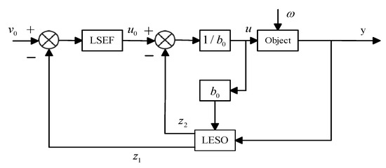
Figure 3.
Second-order linear rejection controller block diagram.
LSEF refers to the linear state error feedback rate. Generally speaking, LSEF in LADRC can be in the form of PD controller, which can realize part of the functions of TD to improve the overall control performance of the system. LESO is a kind of observer used to estimate the state of the system, which can estimate the extended state of the system in real time, including internal dynamics and external disturbances.
LESO can effectively compare the actual state of the system with the expected state in the controller, thus helping the controller to accurately calculate the required compensation control signal.
A first-order linear system can be represented as
In the equation, is the input value, is the output value, is the gain, is the control parameter and represents the external disturbance.
The generalized disturbance equation can be expressed as
In the equation, is an estimate of the system .
For the aforementioned equation, by selecting state variables as follows, the equation can be further derived:
The expression for the LESO is
In the equation, is the tracking signal of , and tracks the total disturbance .
By selecting appropriate observer gains, real-time tracking of system variables can be achieved, and the control rate can be designed as
In a first-order LADRC, a proportional controller is commonly used instead of LESF, and the equation is expressed as
The controlled object can be set as
In the equation, represents the given controlled signal, is the controller coefficient, is the controller bandwidth and is the observer bandwidth.
The closed-loop transfer function of a first-order feedback system is given by
The LADRC controller system’s disturbance term and tracking term are both related to , demonstrating a coupling relationship between the two. This coupling makes it challenging to adjust parameters. Additionally, from Equation (15), it can be inferred that while increasing the observer bandwidth is beneficial for enhancing the disturbance observation capability of traditional LESO, the presence of observation noise limits the practical adjustment of the bandwidth in engineering applications.
4.1.2. Design of Circulating Current Suppressor Based on Traditional LADRC
Treating each harmonic component in the circulating current as an external disturbance, compensation is achieved through LESO. Subsequently, a circulating current suppression strategy based on LADRC is designed, and the suppression process is illustrated in Figure 4. Firstly, according to Equation (6), obtain the three-phase circulating current , and through Park transformation, derive circulating currents and . Similarly, compare them with their respective reference values and . When the reference value is set to zero, it can effectively suppress the second harmonic in the circulating current; through the LADRC controller, the circulating current drops , are obtained and, finally, the three-phase circulating current drops are obtained through the inverse Park transformation.

Figure 4.
Diagram of the circulation suppression process.
4.1.3. MMC Control System Based on LADRC Circulating Current Suppressor
In this paper, double closed loop feedforward decoupling control is adopted in the main control part of MMC, and the control structure diagram is shown in Figure 5 [39,40]. In the figure, according to the two PI controllers, the output reference voltages and . These are then converted into three-phase voltage reference values through Park inverse transformation. represents the circulatory voltage drop obtained through the circulation suppression control strategy. Finally, the corresponding PWM pulse signals for controlling the sub-module switches are generated through the nearest level approximation. “*” represents the reference value of the corresponding quantity.
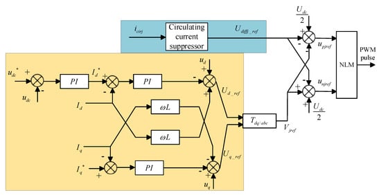
Figure 5.
MMC structure control chart.
4.2. Design of Circulating Current Suppressor Based on AD−LADRC
4.2.1. Improving the Structural Design of LESO
In order to achieve faster and more effective circulation suppression, this paper introduces an additional state variable on the basis of the traditional second-order LESO. This variable is utilized to observe the changing trend of the total disturbance. Simultaneously, improvements are made to compensate for the total disturbance, enhancing the structure of the extended state observer for the decoupling of disturbance and tracking terms. The improvement in the LADRC is illustrated in Figure 6. The expression for the improved LESO is as follows:
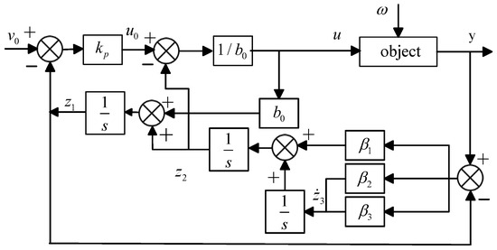
Figure 6.
AD−LADRC structure diagram.
Applying the inverse Laplace transform to Equation (17) yields
The disturbance observation transfer function of the improved LESO is
In the formula, the gains are
Based on Equations (11)–(13) and (17), the closed−loop transfer function of AD-LADRC is as follows:
From Equations (19) and (21), it can be observed that compared to the closed−loop transfer function of the traditional LADRC control system, the AD-LADRC introduces an increased LESO bandwidth. The disturbance term is only influenced by , and , while the tracking term is only related to . This achieves the decoupling of disturbance and tracking terms. From Figure 7, it is evident that the system bandwidth of the improved LESO has significantly increased, and there is a substantial reduction in the phase lag in the mid−frequency range.
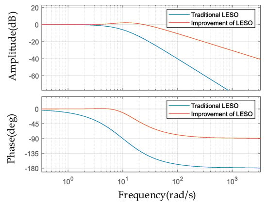
Figure 7.
Disturbance observation transfer function characteristic curve.
4.2.2. Analysis of Suppressor Performance
- (1)
- Frequency Domain Characteristics of Changes
From Equation (17), the transfer functions for observation noise and input disturbance are derived as follows:
When is fixed and is set to 10, 20, 30, 40 and 50, respectively, the frequency domain characteristic curves are obtained as shown in Figure 8a, Observation Noise. From the graph, it can be seen that as increases step by step, the response speed of the improved suppressor is enhanced. This reduces the high-frequency noise gain on its output side, effectively suppressing the equivalent measurement noise on the input side.
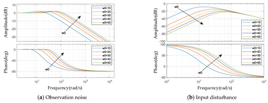
Figure 8.
Frequency domain characteristic curves at different bandwidths.
According to Equation (23), when is set to 10, 20, 30, 40 and 50, the frequency domain characteristic curves of this transfer function are obtained in Figure 8b, Input Disturbance. It can be observed from the graph that increasing can reduce the gain of the disturbance term, enhance the system’s disturbance rejection performance and have a significant impact on mid- to low-frequency disturbances.
- (2)
- Frequency Domain Characteristic Curves of LADRC Before and After Improvement
Comparison of the frequency domain characteristic curves for LADRC before and after improvement is shown in Figure 9. The improved LADRC exhibits superior performance in terms of both speed and robustness compared to the traditional LADRC, making it better equipped to handle external disturbances.
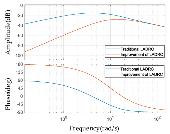
Figure 9.
Comparison of frequency domain characteristic curves.
When the disturbance is a unit step signal, the system output response can be derived from Equation (21) as follows:
Applying the Laplace inverse transform to Equation (24) and taking the limit, we can obtain . Moreover, as the observer bandwidth increases, the rate of decrease in also increases. This indicates that the LADRC with the improved LESO has strong disturbance rejection capabilities.
5. Simulation Analysis
In order to analyze the feasibility of the improved LADRC circulating current suppressor described in this paper, an 18-level modular multilevel converter simulation model is built based on Matlab (9.12.0.1884302 (R2022a)) & Simulink simulation software. The simulation parameters are as shown in Table 1, and controller parameters are as presented in Table 2. The circulation suppression effects of three kinds of circulating current suppressors, bridge arm current and sub-module capacitance voltage under steady state and DC side voltage sudden change are simulated and analyzed, respectively.

Table 1.
Simulation parameters.

Table 2.
Controller parameters.
5.1. Steady-State Operating Condition
5.1.1. Circulation Suppression Effect
Three kinds of circulating current suppressors are put into the HVDC system, namely: PI circulating current suppressor, LADRC circulating current suppressor and AD-LADRC circulating current suppressor. The circulation changes of the MMC bridge arm under the action of three kinds of controllers are simulated and compared, and the results are shown in Figure 10.
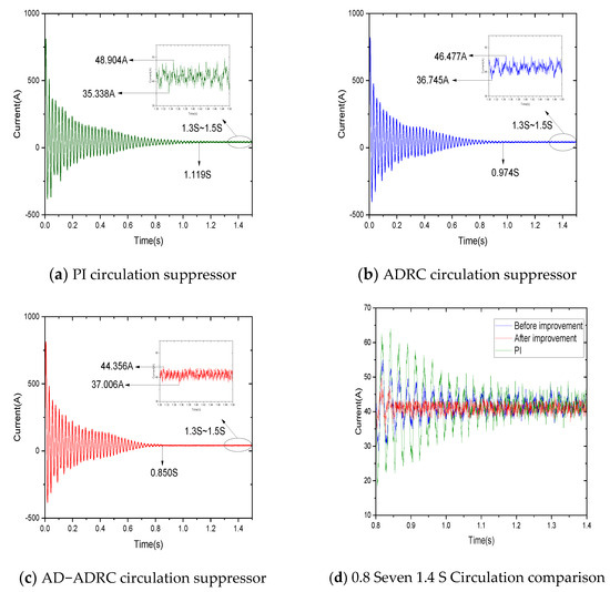
Figure 10.
Simulation diagram of circulation suppressor.
Figure 10a–c shows the circulation waveforms of the PI circulation suppressor, the LADRC circulation suppressor and the AD-LADRC circulation suppressor in turn. Figure 10d is a comparison of the 0.8 S~1.4 S waveforms selected from the above three figures in order to clearly observe that the suppression effect of the improved controller is better. Observe Figure 10a: when the circulation reaches a steady state at 1.119S, select and enlarge the 1.3 S~1.5 S waveform; the upper peak of the circulation is 48.904 A, the lower peak is 35.338 A and the peak difference is 13.566 A. Observe Figure 10b: when the circulation reaches a steady state at 0.974 S, select and enlarge the 1.3 S~1.5 S waveform; the upper peak is 46.477 A, the lower peak is 38.745 A and the peak difference is 9.732 A. Observe Figure 10c: when the circulation reaches a steady state at 0.850 S, select and enlarge the 1.3 S~1.5 S waveform; the upper peak is 44.356 A, the lower peak is 37.006 A and the peak difference is 7.350 A. In terms of stabilization time, the improved circulation suppressor is 24.04% and 12.73% shorter than that of PI and LADRC, respectively. In terms of peak deviation, the improved circulation suppressor is reduced by 45.82% and 24.48% compared with PI and LADRC, respectively. This shows that during the steady-state operation of the system, the improved circulation suppressor has been effectively improved in terms of speed and stability.
5.1.2. Arm Current and Sub-Module Capacitor Voltage
The simulation analysis of bridge arm current and sub-module capacitance voltage is an important means to evaluate the performance of HVDC system, and the waveform reflects the suppression effect of the circulating current suppressor. The simulation waveforms of the A-phase bridge arm current and sub-module capacitor voltage using the AD−LADRC circulatory suppressor are shown in Figure 11 and Figure 12.
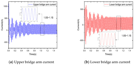
Figure 11.
A−phase bridge arm current.
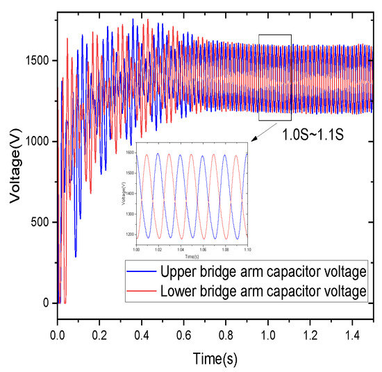
Figure 12.
A-phase sub-module capacitor voltage.
The second harmonic component is significantly suppressed. By analyzing the waveform from 1.0 S to 1.1 S, it is observed that the bridge arm current waveform tends to be sinusoidal with fluctuations ranging between −165 A and 250 A. Furthermore, the fluctuation amplitude and waveform distortion rate of the capacitor voltage are significantly reduced, with a fluctuation range of 1150 V to 1600 V.
In addition, in order to directly reflect the influence of suppressor on the system, the bridge arm current and capacitor voltage when the suppressor is used or not are compared, as shown in Figure 13. The above bridge arm current is taken as an example. Figure 13a shows the A phase bridge arm current using the suppressor, and Figure 13b shows the A phase bridge arm current without the suppressor. It can be seen from the figure that the waveform of the bridge arm current is obviously distorted due to the harmonic generated by the circulation current. The use of the suppressor can improve the influence of the circulation current and make the waveform closer to the sine wave. The peak current difference of bridge arm with the suppressor is 4.933 A and that without the suppressor is 29.305 A.
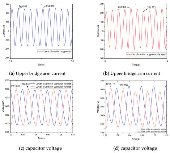
Figure 13.
The effect of whether or not a suppressor is used on the arm current and capacitance voltage.
The capacitance voltage waveforms of sub-modules with and without suppressors are depicted in Figure 13c and Figure 13d, respectively. It is evident from the figures that the difference in capacitance voltage peak between sub-modules with suppressors is 1.956 A, whereas for those without suppressors it is 23.719 A. Consequently, the utilization of suppressors leads to a significant reduction in both the range of capacitance voltage fluctuation and the waveform distortion rate.
5.1.3. Bridge Arm Current THD
The harmonic analysis of the bridge arm current is helpful to understand the harmonic content of the system, and a good controller should be able to restrain harmonics effectively and ensure the stable operation of the system. Through the FFT analysis, it can further see the suppression effect of the suppressor on the second harmonic component of the bridge arm current. Taking t = 1.3S and 20 cycles as an example, as shown in Figure 14, when no circulation suppressor is used, the bridge arm current THD is 9.74%;when using the PI circulation suppressor, the bridge arm current THD is 1.82%; when using the LADRC circulation suppressor, the bridge arm current THD is 1.71%; and when using the AD-LADRC circulation suppressor, the bridge arm current THD is 1.63%, all of which are less than the 3% to 5% required for different grid−connection standards. Compared with PI and LADRC, the THD value of the AD-LADRC circulation suppressor proposed in this paper is reduced by 10.44% and 4.68%, respectively.
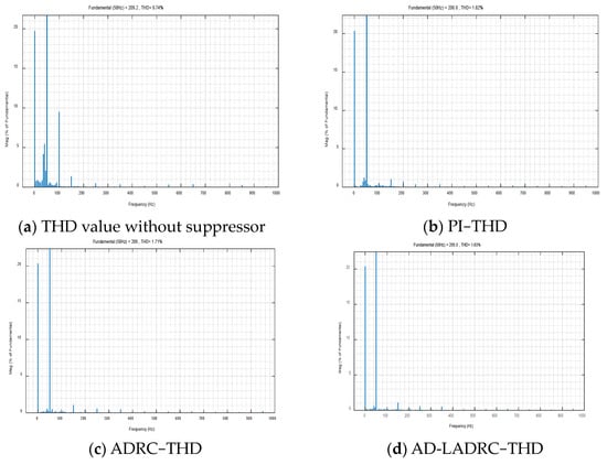
Figure 14.
Bridge arm current THD.
5.2. DC Voltage Transient
By introducing DC side voltage sudden change, the dynamic response of the HVDC system in the face of voltage sudden change can be simulated, and the dynamic performance of the circulating current suppressor can be tested. Adjust the DC side voltage to 18 KV at 1.5 s, as shown in Figure 15.
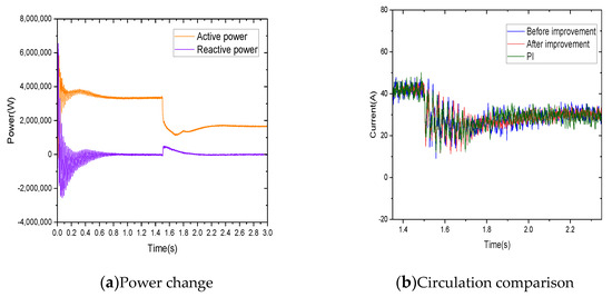
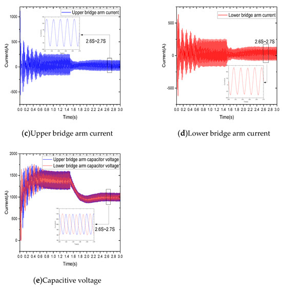
Figure 15.
Voltage mutation simulation comparison.
As can be seen from Figure 15a, the system undergoes a voltage disturbance at 1.5S, and the current suppressor continues to function properly. The power waveform remains relatively stable, with active power tracking the reference well and reaching a steady state. Reactive power is essentially maintained at zero, indicating that the system is in an active grid-connected state.
The 1.35 S~2.35 S waveform is selected as shown in Figure 15b; the performance of the improved circulating current suppressor is better than the traditional controller. The former has a smaller oscillation amplitude and requires less time to reach stability. Moreover, observing the A-phase bridge arm current in Figure 15c,d and sub-module capacitance voltage in Figure 15e at this time, it can be corrected in time in the face of sudden voltage change, and the waveform is flat. Select 2.6S~2.7S waveforms, respectively; the bridge arm current fluctuates in the range of −75~135 A, and the A-phase sub-module capacitor voltage fluctuates in the range of 900~1100 V. Performing FFT analysis on the bridge arm current at this time, the improvement is 2.29%, the improvement before is 2.74% and PI is 2.89%. This indicates that the improved circulating current controller has excellent anti-interference capability and suppression effects.
6. Conclusions
In this paper, by combining MMC-HVDC transmission technology with an offshore wind farm, the mechanism of negative sequence current circulation dominated by second harmonic generation in MMC is analyzed. Based on the traditional LADRC circulation suppression strategy, an improved negative sequence current circulation suppression method is proposed. This method can improve the dynamic response ability and anti-interference ability of the system, and the fast performance and anti-disturbance performance are better than the traditional circulation suppression strategy. Through computer simulation, the effects of circulation suppressors of PI, LADRC and AD-LADRC under different working conditions of stable operation and voltage sudden change are compared and analyzed. The results show that
- (1)
- The improved circulating current suppressor can effectively improve the waveform distortion effect of the bridge arm current. In terms of stabilization time, the improved circulating current suppressor is 24.04% and 12.73% shorter than PI and LADRC, respectively. In terms of peak deviation, the improved circulation suppressor is reduced by 45.82% and 24.48% compared with PI and LADRC, respectively.
- (2)
- The second harmonic component is obviously suppressed, and the influence of the circulation can be improved after using the suppressor, so that the waveform is closer to the sine wave.
- (3)
- The fluctuation amplitude of the capacitor voltage and the rate of waveform distortion decreased obviously. The peak difference of the capacitor voltage of the sub-module with suppressor was 1.956 A and that of the sub-module without suppressor was 23.719 A.
- (4)
- When the circulating current suppressor is not used, the bridge arm current THD is 9.74%. When using a PI circulating current suppressor, the bridge arm current THD is 1.82%. When using a LADRC circulating current suppressor, the bridge arm current THD is 1.71%. When using an AD-LADRC circulating current suppressor, the bridge arm current THD is 1.63%. The THD is controlled within the range of 3% THD, and the improved controller is reduced by 10.44% and 4.68% compared with PI and LADRC, respectively.
- (5)
- The increased-order decoupling auto−disturbance rejection suppressor proposed in this paper has stronger rapidity, adaptability and robustness, which is helpful to improve the grid-connected ability of offshore wind farms and provide some theoretical and application support for the development and large-scale utilization of offshore wind power.
Author Contributions
Conceptualization, X.X. and D.W.; methodology, X.X., X.Z. and L.T.; software, D.W.; validation, X.X. and D.W.; formal analysis, X.Z.; investigation, D.W. and L.T.; resources, X.X.; datacuration, D.W.; writing—original draft preparation, D.W.; writing—review and editing, X.X. and X.Z.; visualization, D.W.; supervision, X.X.; project administration, X.X.; funding acquisition, X.X. All authors have read and agreed to the published version of the manuscript.
Funding
This research was funded by the Tianjin Science and Technology Program: Deep Learning-based Wind Power Prediction and Self-Anti Disturbance Control Methods and Engineering Applications, grant number 23YDTPJC00530, and the APC was funded by the Tianjin Science and Technology Program: Deep Learning-based Wind Power Prediction and Self-Anti Disturbance Control Methods and Engineering Applications.
Institutional Review Board Statement
Not applicable.
Informed Consent Statement
Not applicable.
Data Availability Statement
Data are contained within the article.
Conflicts of Interest
The authors declare no conflicts.
References
- Zeng, M.; Cai, Y.; Shen, K. Optimal configuration of new energy grid connected energy storage capacity from the perspective of dual carbon. Int. J. Energy Technol. Policy 2023, 18, 326–342. [Google Scholar] [CrossRef]
- Watson, C.S.; Somerfield, J.P.; Lemasson, J.A. The global impact of offshore wind farms on ecosystem services. Ocean Coast. Manag. 2024, 249, 107023. [Google Scholar] [CrossRef]
- Faraggiana, E.; Ghigo, A.; Sirigu, M.; Petracca, E.; Giorgi, G.; Mattiazzo, G.; Bracco, G. Optimal floating offshore wind farms for Mediterranean islands. Renew. Energy 2024, 221, 119785. [Google Scholar] [CrossRef]
- Han, S.; Rui, H.; Hugo, M. Power quality monitoring in electric grid integrating offshore wind energy: A review. Renew. Sustain. Energy Rev. 2024, 191, 114094. [Google Scholar]
- Joanna, S.; Mariusz, C.; Joanna, P. Reliability of Renewable Power Generation using the Example of Offshore Wind Farms. Folia Oeconomica Stetin. 2023, 23, 228–245. [Google Scholar]
- Samsó, R.; Crespin, J.; Olivares, G.A. Examining the Potential of Marine Renewable Energy: A Net Energy Perspective. Sustainability 2023, 15, 8050. [Google Scholar] [CrossRef]
- Olczak, P.; Surma, T. Energy Productivity Potential of Offshore Wind in Poland and Cooperation with Onshore Wind Farm. Appl. Sci. 2023, 13, 4258. [Google Scholar] [CrossRef]
- Milad, S.; Mateo, R.; Alejandro, H.; Rodrigo, A. A Review of Offshore Renewable Energy in South America: Current Status and Future Perspectives. Sustainability 2023, 15, 1740. [Google Scholar]
- Mohammad, B.; Turaj, A.; Deniz, S.V. Floating Offshore Wind Turbines: Current Status and Future Prospects. Energies 2022, 16, 2. [Google Scholar]
- David, G.; Jensen Paul, D. Chasing after the wind? Green economy strategies, path creation and transitions in the offshore wind industry. Reg. Stud. 2022, 56, 1671–1682. [Google Scholar]
- Zhong, P.; Rong, Y.; Tai, L. Optimization Design of Voltage Level of Flexible DC Transmission with Offshore Wind Power Based on Genetic Algorithm. J. Phys. Conf. Ser. 2023, 2527, 012066. [Google Scholar]
- Mujahid, E.; Pillai, A.C.; Longbin, T. Implications of wave–current interaction on the dynamic responses of a floating offshore wind turbine. Ocean Eng. 2024, 292, 116571. [Google Scholar]
- González, G.W.; Montoya, D.O.; Rodríguez, T.L.C. Optimal Integration of Flexible Alternating Current Transmission Systems in Electrical Distribution Grids Using a Mixed-Integer Convex Model. Algorithms 2023, 16, 420. [Google Scholar] [CrossRef]
- Peng, L.; Fu, Z.; Xiao, T. An Improved Dual Second-Order Generalized Integrator Phased-Locked Loop Strategy for an Inverter of Flexible High-Voltage Direct Current Transmission Systems under Nonideal Grid Conditions. Processes 2023, 11, 2634. [Google Scholar] [CrossRef]
- Jiaqi, W.; Zhichao, F.; Xin, L.; Daoyuan, M. A PLL-free control strategy for flexible DC transmission systems. Energy Rep. 2022, 8, 1413–1420. [Google Scholar]
- Zhu, S.; Liu, K.; Qin, L.; Qing, W.; Yuye, L. Analysis and suppression of DC oscillation caused by DC capacitors in VSC-based offshore island power supply system. IEEJ Trans. Electr. Electron. Eng. 2019, 14, 545–555. [Google Scholar] [CrossRef]
- Mengting, C.; Peiqiang, S.; Guipeng, C.; Fengyan, F.; Xinlin, Q. Multiple criteria analysis for electrifying off-grid island using renewable energy microgrid or submarine cable. Electr. Power Syst. Res. 2023, 224, 109728. [Google Scholar]
- Weili, Z.; Tianning, Z. Application of Flexible DC Transmission Technology in Power Grid under Large-scale Development of New Energy. IOP Conf. Ser. Earth Environ. Sci. 2020, 440, 032035. [Google Scholar]
- Chenhao, L.; Kuan, L.; Changhui, M.; Pengfei, Z.; Qi, T.; Yingtao, S.; Xin, W. Flexible control strategy for HVDC transmission system adapted to intermittent new energy delivery. Glob. Energy Interconnect. 2021, 4, 425–433. [Google Scholar]
- Xingyang, H.; Kun, C.; Ting, W.; Zengrui, H. Analysis of typical fault characteristics of modular multilevel converter for flexible HVDC transmission. J. Phys. Conf. Ser. 2022, 2369, 012067. [Google Scholar]
- Pan, R.; Yang, Y.; Yang, J.; Liu, D. Enhanced grid forming control for MMC-HVDC with DC power and voltage regulation. Electr. Power Syst. Res. 2024, 229, 110166. [Google Scholar] [CrossRef]
- Pan, R.; Liu, D.; Yang, Y.; Yang, J. Network based impedance analysis of grid forming based MMC-HVDC with wind farm integration. Electr. Power Syst. Res. 2024, 229, 110120. [Google Scholar] [CrossRef]
- Xiaolei, W.; Quan, Z.; Jianying, Z. Control Strategy of Circulating Current Suppression for Modular Multilevel Converter. J. Phys. Conf. Ser. 2023, 2564, 012005. [Google Scholar]
- Chun, W.; Wenxu, Y.; Wenyuan, W.; Hongyu, N.; Jie, C. The Suppression of Modular Multi-Level Converter Circulation Based on the PIR Virtual Impedance Strategy. World Electr. Veh. J. 2023, 14, 17. [Google Scholar]
- Manchala, R.N.; J, S.; Mandi, P.R. Circulating Current Suppression Control in Surrogate Network of MMC- HVDC System. Int. J. Recent Technol. Eng. 2020, 8, 29–34. [Google Scholar]
- Debdeep, S.; Tanmoy, B.; Saurav, D. A Reduced Switching Frequency Sorting Algorithm for Modular Multilevel Converter with Circulating Current Suppression Feature. IEEE Trans. Power Electron. 2019, 34, 10480–10491. [Google Scholar]
- Jinyu, W.; Jun, L.; Chengfu, W.; Chengfu, W.; Xiaoming, D. Circulating Current Suppression for MMC-HVDC under Unbalanced Grid Conditions. IEEE Trans. Ind. Appl. 2017, 53, 3250–3259. [Google Scholar]
- Mingguang, Z.; Yao, S.; Huzhong, S.; Richang, G. MMC-HVDC circulating current suppression method based on improved proportional resonance control. Energy Rep. 2020, 6, 863–871. [Google Scholar]
- Qingrui, T.; Zheng, X.; Minyuan, G.; Xiang, Z.; Jing, Z. Design of circulating current suppression controller for modular multilevel converter. Power Syst. Autom. 2010, 34, 57–61. [Google Scholar]
- Xiahui, Z.; Minxiao, H.; Jinggang, Y.; Xiangkun, M.; Zijian, Q. Analysis of the influence mechanism of DC side voltage fluctuation on the circulating current of MMC and its suppression method. Power Syst. Autom. 2021, 45, 122–131. [Google Scholar]
- Semih, I.; Mohammed, A.; Subhashish, B. An Optimized Circulating Current Control Method Based on PR and PI Controller for MMC Applications. IEEE Trans. Ind. Appl. 2021, 57, 5074–5085. [Google Scholar]
- Zhouzhou, L. MMC-HVDC control and circulation suppression strategy based on quasi-PR controller. J. Power Syst. Autom. 2016, 28, 70–75. [Google Scholar]
- Xianzheng, L.; Xingcheng, W.; Kai, Z. IMC based circulating current controller for MMC-HVDC. In Proceedings of the 2017 36th Chinese Control Conference (CCC), Dalian, China, 26–28 July 2017; pp. 617–622. [Google Scholar]
- Jingqing, H. Auto disturbance rejection controller and its application. Control. Decis. 1998, 13, 19–23. [Google Scholar]
- Fang, Z.; Guangyao, Z.; Yan, C. MMC Circulation suppression Strategy based on Linear Auto disturbance rejection Control. J. Electr. Power Syst. Its Autom. 2018, 30, 71–78. [Google Scholar]
- Yang, X.; Li, Z.; Zheng, Q.T.; Zheng, T. Virtual Impedance Sliding Mode Control-Based MMC Circulating Current Suppressing Strategy. IEEE Access 2019, 7, 26229–26240. [Google Scholar] [CrossRef]
- Farooq, A. Influence of Unified Power Flow Controller on Flexible Alternating Current Transmission System Devices in 500 kV Transmission Line. J. Electr. Electron. Eng. 2018, 6, 12–19. [Google Scholar] [CrossRef]
- Zhang, G.; Song, J.; Li, C.; Gu, X. A Circulating Current Suppression Strategy for MMC Based on the 2N+1 PWM Approach. World Electr. Veh. J. 2023, 14, 106. [Google Scholar] [CrossRef]
- Kun, W.; Kaipei, L.; Zhixuan, Z.; Wei, L.; Liang, Q. Capacitor voltage equalization strategy of modular multilevel converter based on fast sorting algorithm. Electr. Meas. Instrum. 2018, 55, 1–7. [Google Scholar]
- Xitang, T.; Hongmei, Z.; Qinyue, Z.; Jiangbin, C. Capacitor voltage fluctuation analysis and equalization control of MMC module. Power Electron. Technol. 2016, 50, 1–4. [Google Scholar]
Disclaimer/Publisher’s Note: The statements, opinions and data contained in all publications are solely those of the individual author(s) and contributor(s) and not of MDPI and/or the editor(s). MDPI and/or the editor(s) disclaim responsibility for any injury to people or property resulting from any ideas, methods, instructions or products referred to in the content. |
© 2024 by the authors. Licensee MDPI, Basel, Switzerland. This article is an open access article distributed under the terms and conditions of the Creative Commons Attribution (CC BY) license (https://creativecommons.org/licenses/by/4.0/).