Article

Design and Experimental Study of 50 kW Ocean Thermal Energy Conversion Test Platform Based on Organic Rankine Cycle

1
Institute of Marine Science and Technology, Shandong University, Qingdao 266237, China
2
Key Laboratory of High Efficiency and Clean Mechanical Manufacture, Ministry of Education, School of Mechanical Engineering, Shandong University, Jinan 250061, China
3
Southern Marine Science and Engineering Guangdong Laboratory (Zhanjiang), Zhanjiang 524006, China
*
Authors to whom correspondence should be addressed.
J. Mar. Sci. Eng. 2024, 12(3), 463; https://doi.org/10.3390/jmse12030463
Submission received: 8 February 2024 / Revised: 3 March 2024 / Accepted: 5 March 2024 / Published: 7 March 2024
(This article belongs to the Special Issue Offshore Renewable Energy)

Abstract

:
In recent years, clean and renewable energy sources have received much attention to balance the contradiction between resource needs and environmental sustainability. Among them, ocean thermal energy conversion (OTEC), which consists of surface warm seawater and deep cold seawater, can rely on thermal cycling to generate electricity and has great potential in alleviating the energy crisis. In this paper, the design and experiment study of a 50 kW OTEC platform is proposed. Thermodynamic modeling, calculation, optimization, and engineering calibration of the system were carried out, and the thermal efficiency reached 2.63% to meet the power generation demand. Experiments were also carried out by using a heat pump unit to simulate hot and cold seawater environments, and data on the stable operation of the system were obtained, with the grid-connected power reaching 47.5 kW and a thermal efficiency of 2.46%. The accuracy of the design scheme is verified, and the theoretical basis and data support are provided for the practical development and application of ocean thermal energy conversion.

1. Introduction

Most of the energy used in the world is fossil fuels. Coal accounts for 70 percent of major energy consumption. Excessive use of fossil fuels produces large quantities of harmful gases, and wastewater emissions are increasing day by day. In recent years, with the gradual deterioration of the global environment, countries around the world have been changing their energy structures, which rely mainly on fossil fuels such as oil and natural gas, and have been actively advocating and developing the use of new and renewable energy sources with more and more attention being paid to ocean energy [1,2,3,4]. In the United Nations sustainable development agenda for 2030, ocean renewable energies have been explicitly identified as a key objective of sustainable development [5].
There are various forms of renewable energy in the ocean, including ocean wind energy, wave energy, tidal current energy, ocean thermal energy, and salt difference energy [6,7,8]. The ocean thermal energy refers to the heat energy stored between warm seawater (25~30 °C) and deep cold seawater (4~7 °C) on the surface of the ocean that is irradiated by the sun all year round [9]. Compared with other ocean energy sources, the advantages of ocean thermal energy are that it is stable and continuous, has large reserves, and is non-polluting, and the thermal cycle system can be used to complete power generation [10,11]. The South China Sea has huge reserves of ocean thermal energy. Theoretical reserves in China’s offshore and adjacent waters are 14.4 × 10²¹–15.9 × 10²¹ J, and the total installed capacity can be developed from 17.47 × 10⁸–18.33 × 10⁸ kW, 90% of which is distributed in the South China Sea. Actively developing ocean thermal energy can provide an important guarantee for resource development in the South China Sea [12,13,14]. The development of ocean thermal energy conversion can reduce the dependence on fossil energy and reduce carbon dioxide emissions [15]. While improving the environment, it can also obtain a large amount of high-quality deep clean seawater, which is considered to be one of the energy sources with development potential [16,17,18,19].
In 1881, French scientist Arsonval first proposed the feasibility of ocean thermal energy conversion (OTEC) [20]. His student Georges then built the first OTEC factory in 1930 [21]. However, at that time, the technology was not widely used due to its high cost and low energy conversion efficiency. In the 1970s, the oil crisis broke out, and human environmental protection awareness increased. Several countries, mainly France, Japan, and the United States, began to attach importance to the development of ocean energy [22]. In 1970, a small offshore power station with a net output of 15 kW was built in Hawaii [23]. In 1981, the Tokyo Electric Power Company built a 100 kW OTEC onshore test plant with R22 as the working fluid in the Republic of Nauru, with a net output power of 31.5 kW [24]. In 1982, Japan’s Tokushima company established a 50 kW onshore OTEC power plant with R717 as the working fluid [25]. At the same time, the National Institute of Ocean Technology of India and Saga University of Japan reached a cooperation to build an offshore floating OTEC power plant [26], which provided 493 kW of electricity to the grid. In 2013, the U.S. Makai Offshore Engineering Company designed a 100 kW power plant. In the same year, the French DCNS Group successfully constructed and installed on the French island of Reunion an experimental prototype for OTEC, which is a 1/250th scale prototype compared to the proposed 10 MW plant, with the goal of generating 15 kW of equivalent power. In order to make the prototypes as close as possible to the 10 MW OTEC power plant, they use the same operating pressure [27,28,29]. In 2019, the 1 MW OTEC power plant was built in South Korea and underwent offshore trials in Busan, where the actual power generation was only 338 kW due to the design temperature difference between the cooling and heating source systems [30]. In China, the First Institute of Oceanography of the Ministry of Natural Resources successively developed 10 kW and 15 kW OTEC system prototypes in 2006 [31]. In general, OTEC technology has been well applied in tropical ocean areas, such as the Pacific Ocean, Indian Ocean, and Caribbean Sea. More and more countries are actively researching and developing related technologies. However, most of the research related to ocean thermal energy conversion stays at the stage of theoretical analysis, and industrialization development is lagging behind, so there is an urgent need to promote the development of technology and equipment related to the development of ocean thermal energy and provide the necessary technical support for the development of the industry.
Ocean thermal energy conversion systems are divided into the open type [32], closed type [33,34], and hybrid type [35,36] due to their different cycle modes. Among them, the closed-type cycle is widely used because of its easy miniaturization. The organic Rankine cycle [37], as the most basic OTEC closed cycle, is one of the typical sustainable energy technologies that use low-grade energy for power generation.
The 50 kW OTEC power generation platform proposed in this paper is equipped with a cold and heat source control module. The working fluid of the system is R134a. Scholars have conducted a large number of studies and analyses on the advantages and disadvantages of the thermodynamic performance of various refrigerants under ocean thermal energy conditions [38,39,40,41]. In the demonstration equipment and experimental equipment of various countries, the commonly used refrigerants are mainly ammonia and R134a [42]. Although the performance of ammonia is optimal, it is corrosive, toxic, and easy to volatilize, and the incidence of chemical accidents is very high.
However, R134a has a good comprehensive performance. It is non-flammable, non-explosive, non-toxic, non-irritant, non-corrosive, chemically stable, does not have chemical reactions with metals such as iron, copper, and aluminum, and does not destroy the ozone layer. The safety grade is the safest A1, which is a mainstream refrigerant with very high safety and environmental protection and is used in many demonstration power stations developed in Japan and the United States. The experimental test platform for the cycle system circulating agent dosage is very large, and R134a was finally selected as the circulating agent for safety and environmental considerations. [14,43,44]. In the system, Aspen Plus V10 is used to match a suitable water immersion screw chiller to meet the 4 °C/28 °C cooling and heating source conditions. After equipment selection, the 3D packaging experimental platform is designed by Pro-E 5.0 to improve the space utilization. Then, PLC (Programmable Logic Controller) control cabinets for master and slave stations are added to collect analog signals such as the pressure, flow rate, temperature, and valve opening. Finally, the grid-connected inverter feeds the system power into the grid, which improves the resource utilization efficiency and builds a recycling system.
The development and use of ocean thermal energy is based on the system design. This paper about the South China Sea ocean thermal energy application environment focuses on thermodynamic calculation, working fluid selection, system components selection, and engineering verification of the 50 kW ocean thermal energy conversion test platform to carry out the design work, and the heat pump unit simulation of hot and cold seawater environments for experiments has verified the accuracy of the design scheme.

2. Materials and Methods

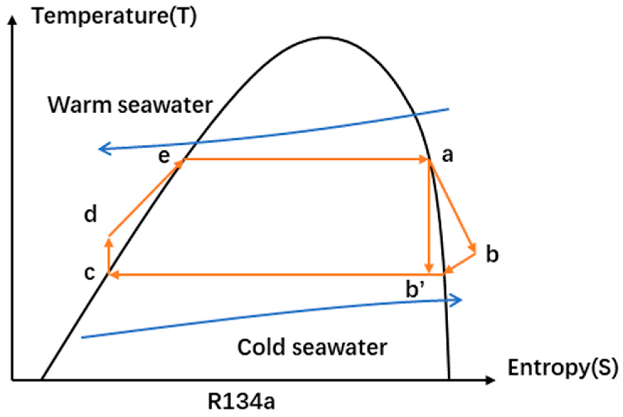
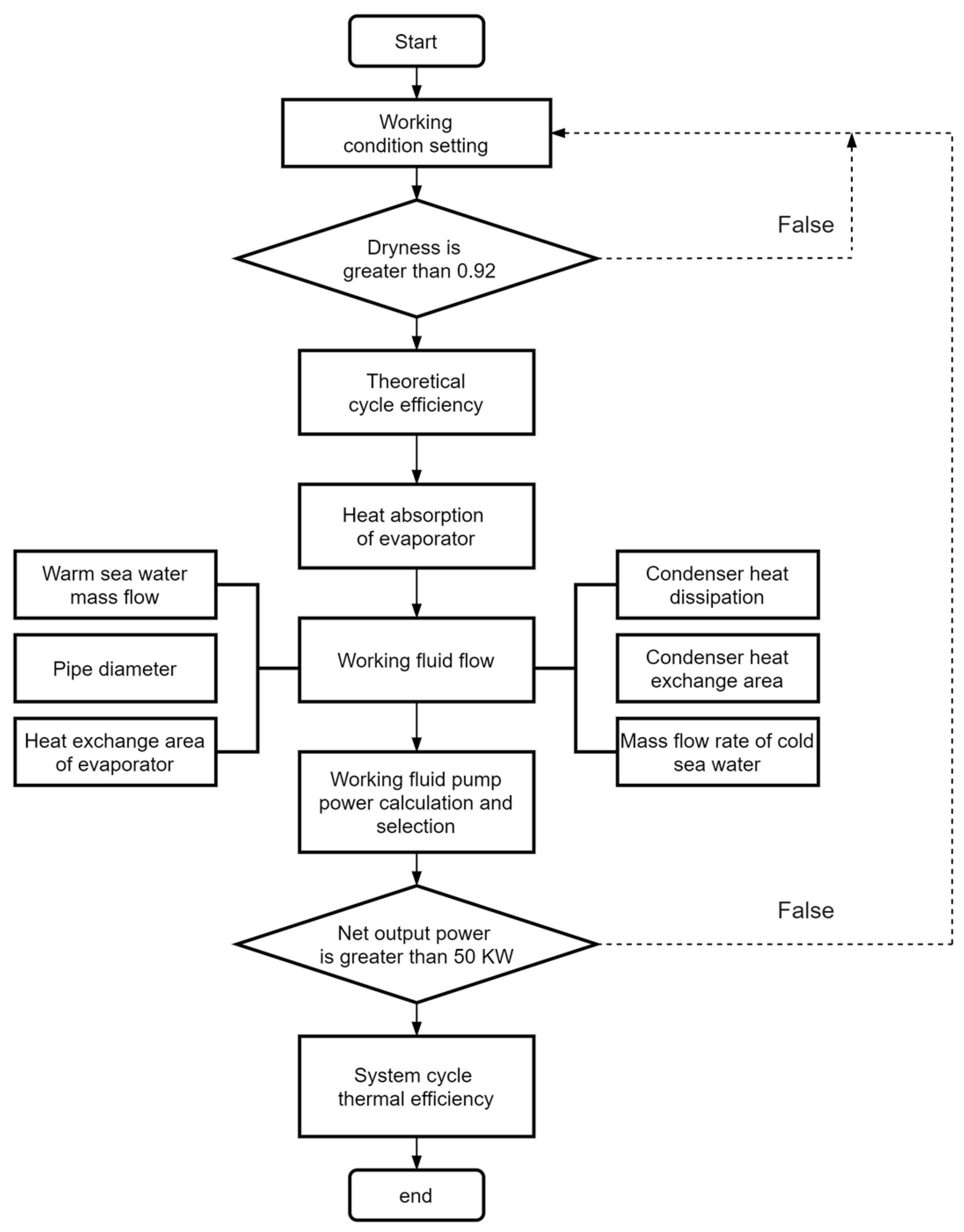
2.1. Platform Principle and Thermodynamic Calculation

In the ideal state without considering any loss, the organic Rankine cycle can be decomposed into four thermodynamic processes: the isentropic expansion process (a~b’), isothermal condensation process (b’~c), isentropic compression process (c~d), and constant pressure heat absorption process (d~e~a) [45,46]. A system temperature entropy diagram is shown in Figure 1. R134a belongs to the wet working fluid [47], and the slope of the saturated steam curve (dT/ds) is negative. The principle of ocean thermal energy conversion power generation is shown in Figure 2, numbers 1~8 represent the working fluid state points at the inlet and outlet of the equipment in the diagram. R134a in the evaporator heated by warm seawater with a surface temperature of 28 °C makes it become saturated steam in the turbine and promotes the turbine to work and generate electricity. The exhaust steam from the turbine outlet enters the condenser, exchanges heat with the cold seawater at the deep temperature of 4 °C, and condenses into liquid. After being supercharged by a working fluid pump, it returns to the evaporator to complete the cycle. It is assumed that the working fluid has no leakage to characterize the steady-state performance of the system; the fluid velocity is constant and incompressible; and its kinetic energy, potential energy, and heat loss are ignored. The transparent entropy efficiency is set to 85%, the efficiencies of the motor and pump are both 90%, and the temperature difference between the inlet and outlet of the seawater is set to 2 °C.
In thermodynamics, specific enthalpy represents the thermal energy per unit mass of a substance under certain conditions. When a substance passes through a system in the form of flow, the heat transferred is the specific enthalpy of previous and subsequent states multiplied by the mass flow.
The energy conservation equation of the heat exchanger is as follows:
Q = m ˙ h = m w c w T
where Q is the amount of heat exchange (kW), h is the specific enthalpy difference between the inlet and outlet of the working fluid side of the heat exchanger (kJ/kg), m ˙ is the mass flow of the working fluid (kg/s), m w is the mass flow of seawater (kg/s), c w is the specific heat capacity of seawater at constant pressure (J/g°C), and T is the seawater side of the heat exchanger temperature rise or drop (°C).
The heat exchange area of the heat exchanger (m2) is as follows:
A = Q k t m
where k is the heat transfer coefficient (W/m2 °C) and t m is the logarithmic heat transfer temperature difference (°C).
The output power of the turbine (kW) is as follows:
W = m ˙ ( h 2 h 3 ) η g η i s
where h 2 is the specific enthalpy of the inlet of the turbine (kJ/kg), h 3 is the specific enthalpy of the outlet of the turbine (kJ/kg), η g is the motor efficiency, and η i s is the entropy efficiency of the turbine.
The isentropic efficiency of the turbine is as follows:
η i s = h 2 h 3 h 2 h 3
where h 3 is the ideal enthalpy value of the turbine outlet ignoring the isentropic efficiency (kJ/kg).
Since the pressure of the working fluid entering the turbine decreases and becomes exhausted steam, it may cause the liquefaction of the gases in the turbine, which can cause impact damage to the turbine blades. Therefore, it is necessary to prevent the working fluid dryness from being too low. Generally, the dryness x of the working fluid at the outlet of the turbine should be greater than 0.92. The calculation formula is as follows:
x = h 2 h 5 h 5 h 5
where h 5 and h 5 are the enthalpy values of the saturated gas and the saturated liquid at the outlet of the condenser (kJ/kg), respectively.
The working fluid pump works (kW) as follows:
W P = m ˙ ( h 7 h 6 ) η P
where η P is the pump efficiency.
The net output work (kW) is as follows:
W n e t = W T W P
The theoretical cycle thermal efficiency is as follows:
η 0 = ( h 2 h 3 ) ( h 7 h 6 ) ( h 1 h 8 )
The thermal efficiency of the system is as follows:
η n e t = W n e t Q e
where Q e is the heat exchange amount of the evaporator (kW).
The optimization process of system thermodynamics calculation is shown in Figure 3. We know the thermodynamic parameters, heat source temperature, cold source temperature, heat transfer end difference, and other working condition settings at each state point. Under the premise of ensuring the dryness of the turbine outlet, firstly, calculate the theoretical cycle of the system efficiency and heat absorption of the evaporator to obtain the working fluid flow; secondly, according to the working fluid flow, enthalpy difference, logarithmic average temperature difference, and heat transfer coefficient, heat exchange capacity, heat exchange area, pump power, working fluid flow, and pipe diameter of cold and hot seawater; finally, select the type according to the pump power of the working fluid and calculate whether the net output power meets 50 kW thermal efficiency. The best working condition setting is obtained through the system’s thermal efficiency results.

2.2. Equipment Selection and Engineering Check

After the thermodynamic optimization calculation of the OTEC system, the selection of key components, valve installation, and piping design can be carried out initially. A specific process flow chart is shown in Figure 4. Each section of the pipeline is equipped with a pressure sensor and temperature sensor for easy measurement. The heat exchanger adopts a full-liquid structure [48], the working fluid goes through the shell side, and the water goes through the tube side. Low-fin threaded tubes are immersed in working fluid, resulting in a large heat exchange area and high heat transfer efficiency. In order to prevent the turbine’s service life from being shortened by the impact of droplets, a gas–liquid separator is added and integrated with the evaporator to increase the space occupancy rate. The turbine adopts a symmetrical and efficient centripetal radial flow type and is directly connected to the generator as an all-in-one machine, with gas bearings support, low vibration, low power consumption, a long service life, and a low maintenance cost. The working fluid pump adopts a hermetic centrifugal canned motor pump and power frequency control, and the flow is bypassed through the bypass regulating valve. The inlet of the evaporator is equipped with a shut-off valve, which is interlocked with the liquid level control; the turbine inlet is equipped with a pneumatic regulating valve, and the outlet has a shut-off check valve, which is connected in parallel with the bypass regulating valve. The condenser outlet is equipped with a shut-off valve; the inlet of the working fluid pump has two shut-off valves and one filter, and the outlet is equipped with a flowmeter.
In actual engineering, the fluid flow resistance caused by the viscous characteristics in the pipeline causes a part of the mechanical energy to be converted into heat energy to be lost. In addition, various valves, flowmeters, filters, and elbows will also cause local energy loss. Therefore, to ensure the smooth implementation of the project, the system is checked, calculated, and corrected.
The head loss along the pipe (m) [49] is as follows:
h f = λ l v 2 2 d g
where l is the pipe length (m), d is the pipe diameter (m), v is the average flow velocity of the cross-section fluid (m/s), g is the acceleration of gravity (m/s2), and λ is the drag coefficient along the way.
When calculating the local head loss, a certain section of local obstacle resistance is converted into a section of straight pipe along the way resistance with the same diameter as the pipe diameter. The length of this section of pipe is called the equivalent length of the local resistance [50], which is represented by l q (m), as follows:
h j = ξ v 2 2 g = λ l q v 2 2 d g
l q = ξ d λ
Then, the total head loss of the entire pipeline (m) is as follows:
h = h f + h j = λ l v 2 2 d g + λ l q v 2 2 d g
The total pressure loss (MPa) is as follows:
P = P f + P j

3. Results and Discussion

3.1. System Design Parameters

The system correction parameters are shown in Table 1 and Table 2.

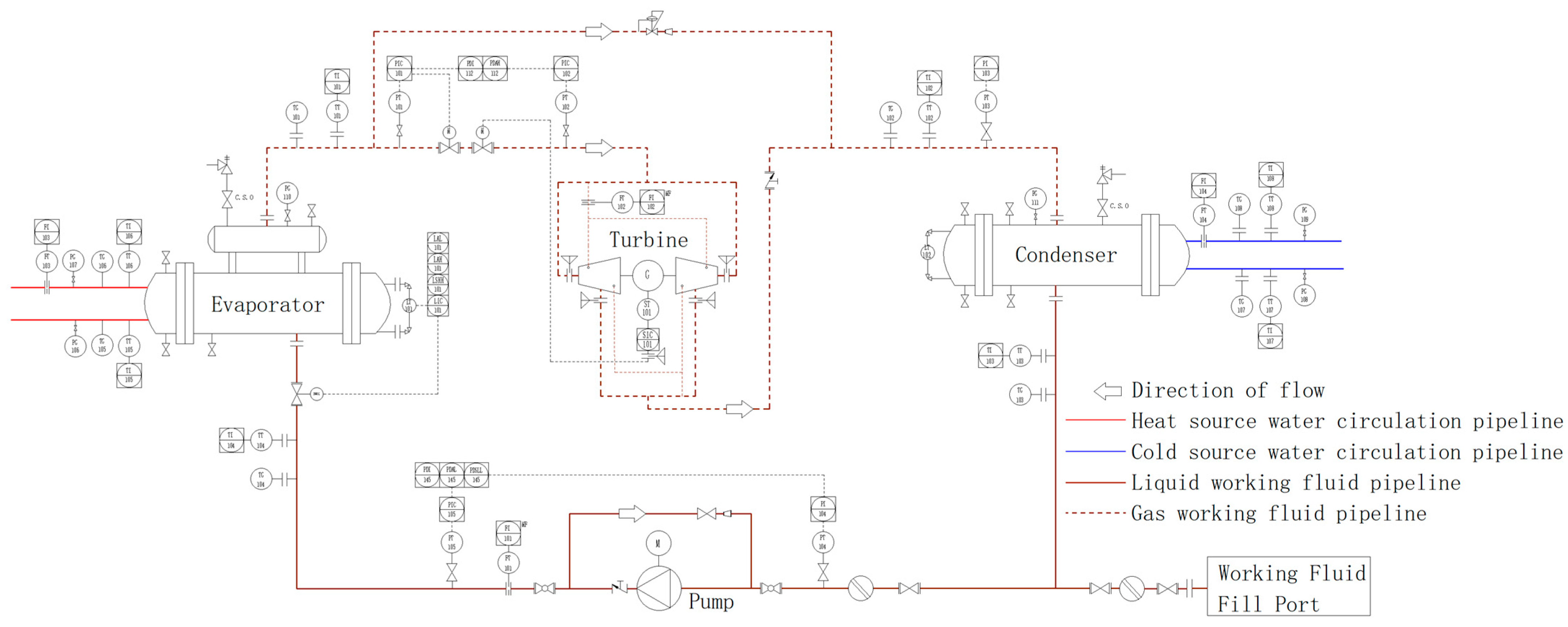
3.2. Overall Structure and Control System

Compared with ordinary dry-type chillers, flooded units have a smaller heat transfer temperature difference and lower outlet superheat, which increases the evaporation temperature and makes full use of the heat exchange area. Therefore, they are more efficient and energy-saving. Screw full-liquid chillers have increasingly become a research and application hotspot of large-scale chillers [51,52].
When the prototype of the power generation system in this paper is running on land, a screw-filled chiller is selected to prepare the cold and heat sources to simulate the 28 °C/4 °C seawater temperature difference to store thermal energy. As shown in Figure 5, the experimental platform consists of an OTEC system and a cold and heat source control system. The cold and heat source control system includes heat pump units (condensers, evaporators, screw compressors), air-cooled auxiliary units (air-cooled condensers, liquid receivers, evaporators, screw compressors), cold and warm water heat exchangers, warm water tanks, a cold water tank, a warm water pump, a cold water pump, an auxiliary water pump, various valves, etc. The physical diagram of the 50 kW OTEC experimental test platform is shown in Figure 6 and Figure 7. Considering factors such as floor space, the organic Rankine cycle module, heat pump unit module, and auxiliary unit module are all skid-mounted, which is convenient for transportation and assembly.
The heat pump unit selects the model LS25LMSA (Moon Environment Technology Co., Ltd., Yantai, China, the same below) screw heat pump refrigerant machine, and the external dimension of the equipment is 6300 × 4000 × 3500 (mm). Among them, the main engine is a twin-screw compressor unit LG25LYA, and the power supply is 3P/50HZ/380V. According to the calculation of Aspen Plus operation, the design working condition of the water-cooled condenser heat transfer is 2187 kW, the waterside inlet temperature is 26 °C, and the outlet temperature is 28 °C; the evaporator design working condition heat transfer is 1863 kW, and the waterside inlet temperature is 6 °C. The outlet temperature is 4 °C. Considering that the summer temperature is higher than 28 °C, the air-cooled auxiliary unit LS16SMFA is added. The heat transfer capacity of the air-cooled condenser is 452 kW in the design working condition, and the heat transfer capacity in the design working condition of the evaporator is 387.8 kW.
The temperature of the cold and heat sources of the system should reach 4 °C/28 °C. First, the cold and warm water heat exchanger should make the water temperature reach about 16 °C after heat exchange. Electricity will increase the temperature difference to meet the requirements. The specific control strategy is when the temperature of the water system is lower than 16 °C, the heat pump unit is turned on, and the temperature of the whole system is raised to 16 °C through the cold and warm water heat exchanger, and then the cold and warm water heat exchanger is bypassed. For the cold water system and warm water system, the temperature difference is increased by external power, reaching 4 °C/28 °C; when the temperature of the water system is higher than 16 °C and lower than 28 °C, the auxiliary unit is turned on, and the cold and warm water heat exchanger is used to reduce the temperature of the entire system to 16 °C. The cold and warm water heat exchanger is then bypassed, the heat pump unit is turned on, and work is performed on the cold and warm water system separately to reach a 4 °C/28 °C working condition; when the temperature of the water system is higher than 28 °C, the auxiliary unit is turned on, and the cold and warm water heat exchanger reduces the temperature of the warm water system to 28 °C. Then, the cold and warm water heat exchanger is bypassed, and the temperature of the cold water system is reduced to 4 °C separately. The system operating conditions and ambient conditions are shown in Table 3 and Table 4, respectively.
As shown in Figure 8, the prototype in this paper is controlled by a two-level electrical system, with data acquisition and monitoring functions for analog signals, such as the pressure, flow, temperature, and valve switches, and can automatically generate graphs and save data in real time. The main station PLC control cabinet is used as the first-level main console, and the method of PLC with an industrial computer is selected as the core processing component. The PLC uses the Siemens SIMATIC S7-1500 model (Moon Environment Technology Co., Ltd., Yantai, China, the same below), and the upper computer uses the Advantech i7 processor industrial computer (Advantech, Beijing, China). As shown in Figure 9, the master station control system can monitor the control systems of each slave station, control the warm water pump, cold water pump, auxiliary water pump, cold and warm water heat exchanger, and the logical relationship between the actions of the units in the entire system to meet different process adjustments. The OTEC system, heat pump unit, and auxiliary unit have their own Siemens SIMATIC S7-1200, which constitutes the second level as a slave station. All the data from the slave station can communicate with the master station through the integrated PROFINET interface of SIMATIC S7-1200, and the data can be uploaded to the integrated PLC control cabinet in real time, and the master station cabinet SIMATIC S7-1500 will carry out integrated control.

3.3. On-Grid System

Aiming for power generation with small temperature differences in the ocean, the traditional grid-connected method is improved, and the grid-connected inverter cabinet is adopted. As shown in Figure 10, the system power is converted into DC power through the rectifier equipment, and then the DC power is converted into the same frequency and phase as the grid. Part of the sine wave current can supply power to the local load, and the surplus power can be fed into the grid, eliminating the need for gearboxes, accumulators, and other components. The grid-connected inverter adopts space vector pulse width modulation technology, pure sine wave output, and automatic and synchronous grid tracking; the power factor is close to 1, the current harmonic content is low, there is no pollution to the public grid, there is no impact, and the power generation efficiency is high.

3.4. Data Acquisition System

Various states in the OTEC system, such as the temperature, pressure, and mass flow rate, are used as the main monitoring data for equipment operation.
In order to understand the internal operation status of the turbine expander, temperature and pressure sensors are installed at the turbine inlet and outlet, and speed-measuring instruments and vibration sensors are installed in the turbine generator set (Suzhou Xida Low Temperature Equipment Co., Ltd., Suzhou, China). In order to understand the status of system operation, temperature sensors and pressure sensors are installed at the inlet and outlet of the evaporator and condenser, respectively, to monitor the temperature and pressure of the simulated seawater; pressure sensors are installed at the inlet and outlet of the working fluid pump, and a flowmeter is installed at the outlet for the measurement of the working fluid mass flow (Moon Environment Technology Co., Ltd., Yantai, China). Measuring equipment models and parameters are detailed in Table 5.

3.5. Experimental Results

Figure 11 shows the variation in the input conditions during the whole system operation, including the temperature and flow rate of warm and cold seawater. Figure 12 reflects the whole process of the system from (1) start-up to (2) stable operation and finally (3) shutdown.
Process (1) is the start-up phase, in which each parameter changes gradually as the opening of the turbine supply valves increases and the opening of the bypass valves decreases, and the output power increases gradually. Process (2) is the stable operation stage: the output parameters of the system can be changed within this range according to the adjustment of the input parameters, maintained in a relatively good control range, without large fluctuations. Process (3) is the shutdown phase, which is the opposite of the valve opening control and start-up process; it can be completed in a relatively short period of time to shut down the experimental equipment.
As can be seen from the experimental process demonstrated in Figure 11 and Figure 12, in the initial stage, the turbine inlet valve is not yet fully open and the bypass pipeline diverts some of the working fluid, resulting in a slow start-up of the turbine. The experiment shows grid-connected power at around 1400 s, and it keeps increasing. When the bypass valve is fully closed, the opening of the turbine inlet valve is about 40%, which leads to a large pressure loss of the working fluid flowing through the valve, so the DC power is kept at a low level. As the opening of the turbine inlet valve gradually reaches 100%, the pressure loss of the mass flowing through the inlet valve decreases and continues in this state for 40 min. Due to the adjustment of the seawater temperature as well as the flow rate, the output power is increasing and the desired design value is reached. The thermal efficiency of the system does not change much as the heat load is also increasing.
Overall, the system is in good operating condition, with gradual changes in the parameters during the start-up phase, and the system can relatively maintain all the parameters within a reasonable range without too much fluctuation during the stable operation phase, and finally a stable shutdown is realized.

4. Conclusions

In this study, a construction scheme of a land-based prototype simulation system for ocean thermal energy conversion with a cold and heat source control module was proposed, and the design and experimental study of a 50 kW ocean thermal energy conversion test platform was carried out in terms of thermodynamic calculations, the selection of the working fluid, the selection of the system components, engineering calibration, and a real-gas test. The following conclusions were obtained:
(1)
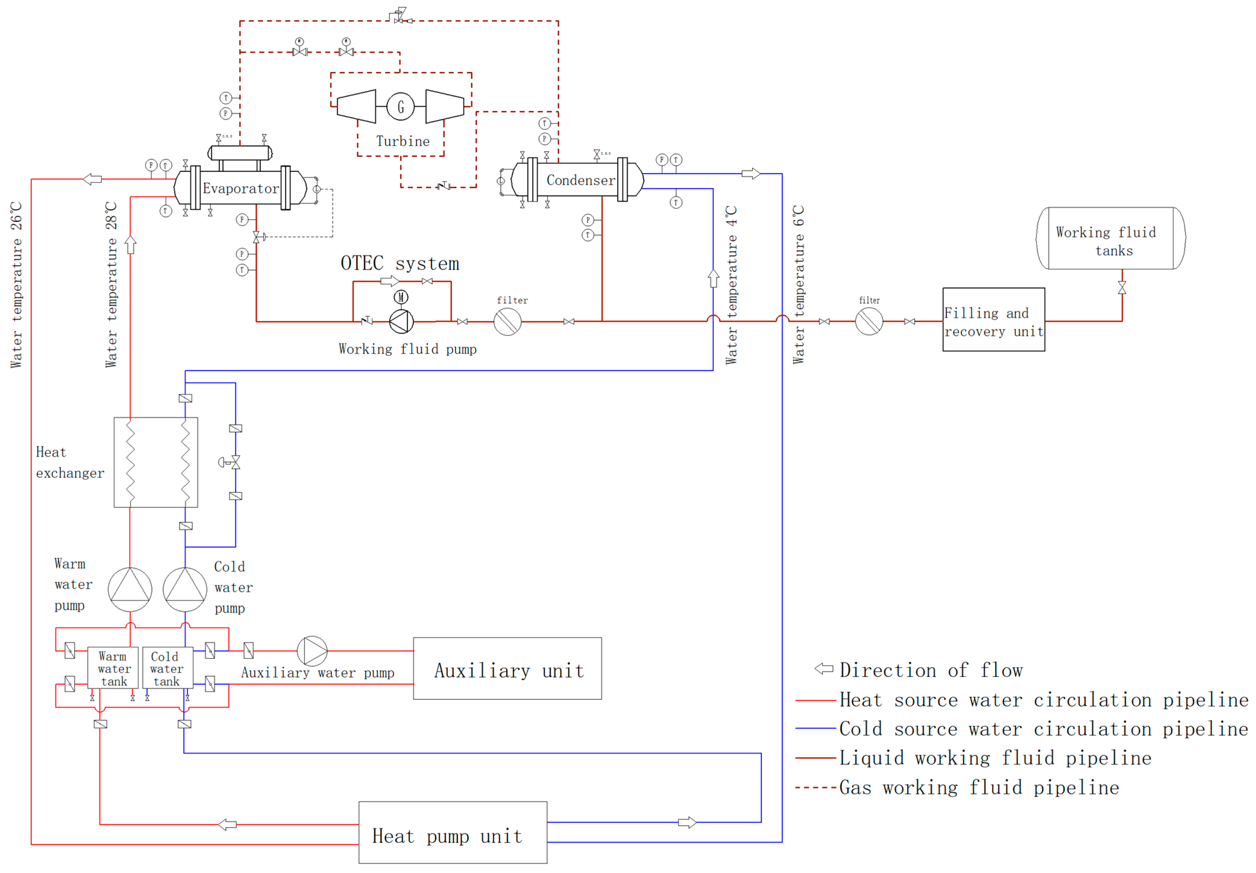
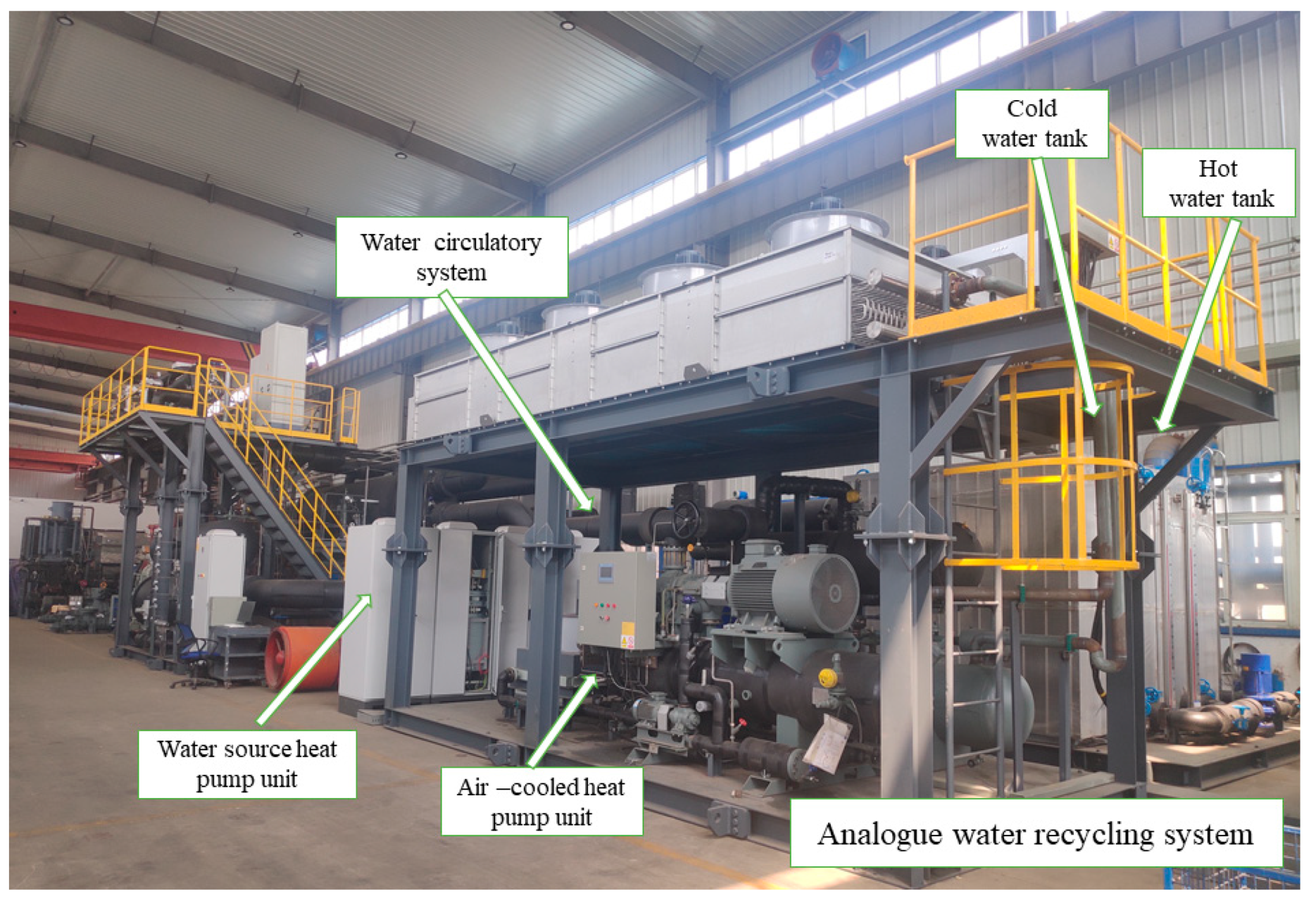
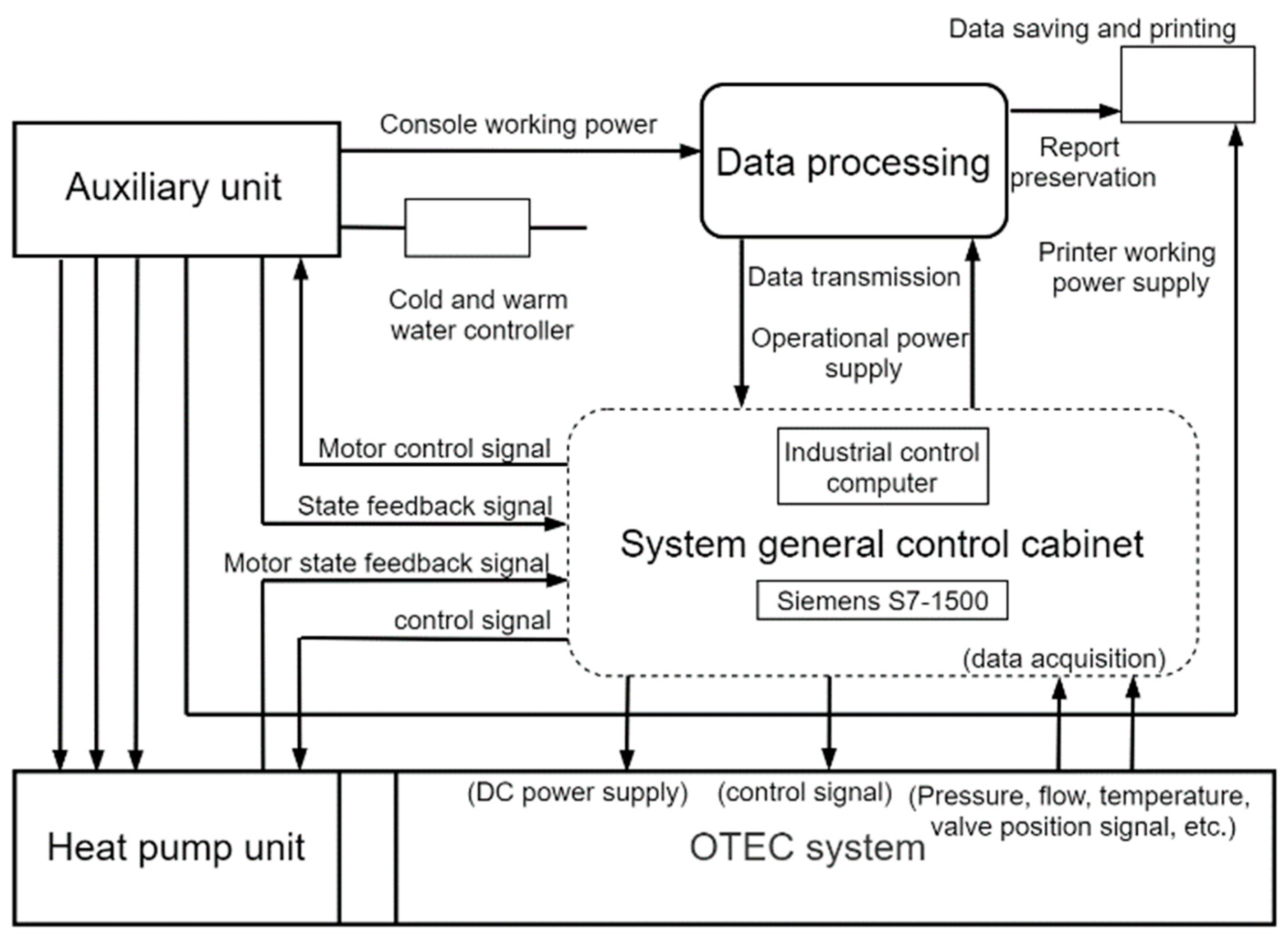
This study proposes a construction scheme for a land-based prototype simulation system for ocean thermal energy conversion with a heat and cold source control module, which includes an OTEC power generation system, a heat pump unit, and an auxiliary unit, and it is skid-mounted using a modular design to increase the compactness of the system. Equipped with a PLC slave control cabinet, it can monitor the slave pressure, flow, temperature, valve switch, and other analog signal data from the master control cabinet.
(2)
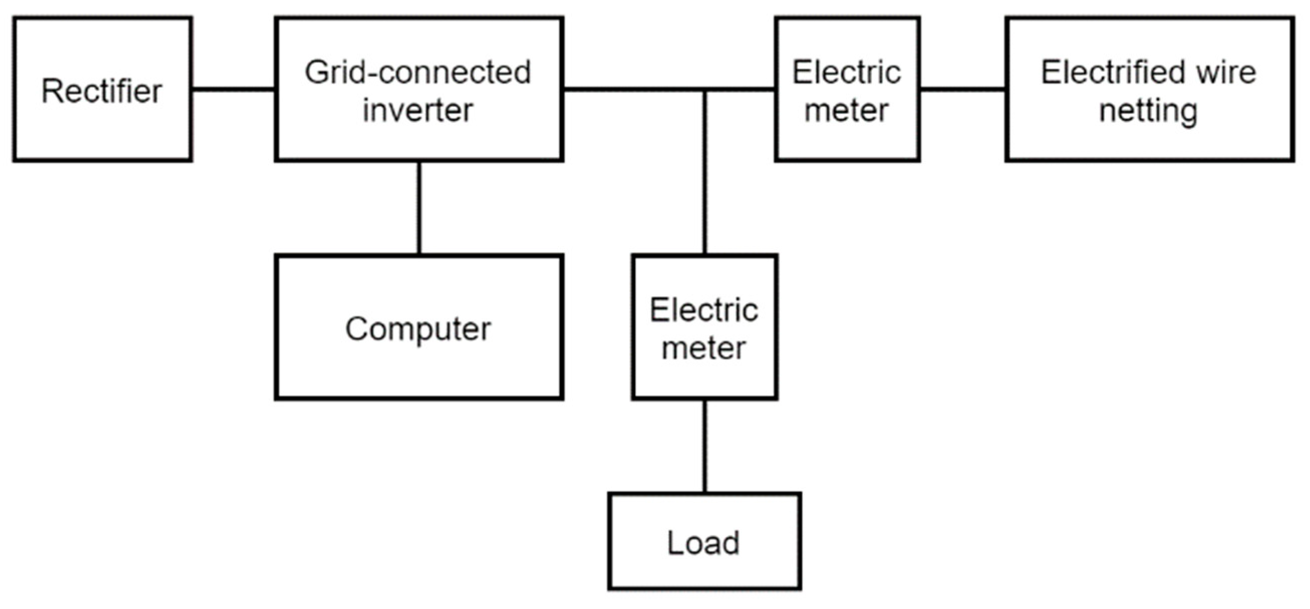
The working medium of the system adopts R134a, which has the characteristics of high safety and good thermal conductivity. After engineering calibration calculation, under the design conditions of a 28 °C heat source temperature and 4 °C cold source temperature, the thermal efficiency of the system is 2.63%, and the output power can be up to 50 kW, which meets the design requirements. The grid-connected inverter sends its power into the grid to achieve reasonable conversion and comprehensive utilization of energy.
(3)
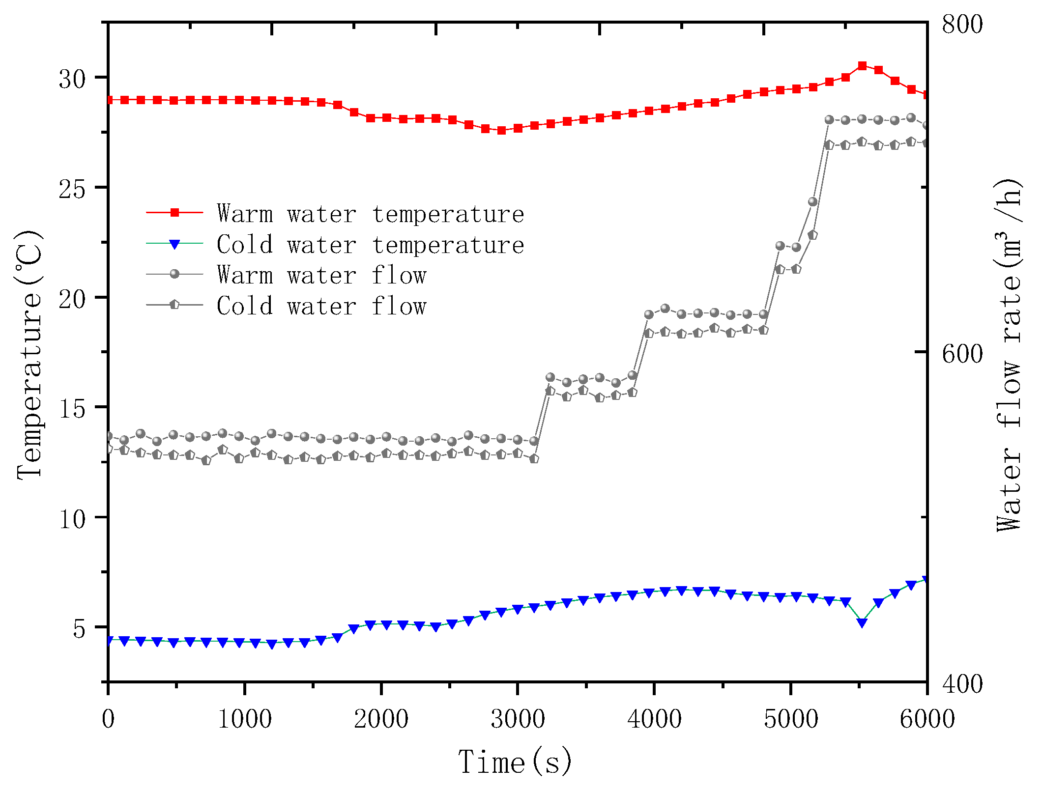
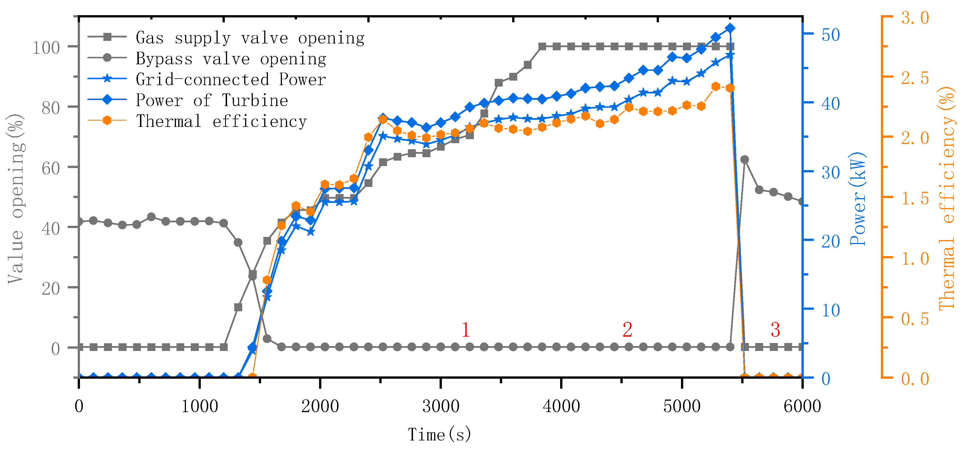
The experimental analysis shows that the cold and heat source simulation system can stably simulate the seawater environment changes (heat source: 24~28 °C and cold source: 4~8 °C), the power generation system can achieve a smooth start-up and shutdown, there is a continuous power output in the stable operation phase, and the maximum grid-connected power reaches 47.4 kW. The actual thermal efficiency is 2.46%.
(4)
As a large ocean thermal energy testing platform in China, the design and experimental research of this experimental platform have achieved good results, which can provide the basis and data support for further research on ocean thermal energy, as well as the experimental simulation basis for further optimization, which is of great significance to the development of ocean thermal energy.

Author Contributions

Conceptualization, B.L. and Y.L.; methodology, X.Z.; software, B.L.; validation, X.Z., B.L. and Y.C.; formal analysis, X.Z. and Y.C.; investigation, B.L.; resources, L.Z.; data curation, Y.C.; writing—original draft preparation, X.Z.; writing—review and editing, Y.L. and Y.C.; visualization, L.Z.; supervision, Y.L.; project administration, Y.L.; funding acquisition, L.Z. All authors have read and agreed to the published version of the manuscript.

Funding

This research was funded by Southern Marine Science and Engineering Guangdong Laboratory (Zhanjiang), grant number: ZJW-2019-05, and the Qingdao Human Resources and Social Security Bureau, the Qingdao Postdoctoral Program: QDBSH20230102007.

Institutional Review Board Statement

Not applicable.

Informed Consent Statement

Not applicable.

Data Availability Statement

Data are contained within the article.

Acknowledgments

Thanks to Yanjun Liu and Yun Chen for their guidance and everyone who contributed to this article.

Conflicts of Interest

The authors declare no conflicts of interest.

References

  1. Martínez, M.L.; Vázquez, G.; Pérez-Maqueo, O.; Silva, R.; Moreno-Casasola, P.; Mendoza-González, G.; López-Portillo, J.; MacGregor-Fors, I.; Heckel, G.; Hernández-Santana, J. A systemic view of potential environmental impacts of ocean energy production. Renew. Sustain. Energy Rev. 2021, 149, 111332. [Google Scholar] [CrossRef]
  2. Feng, C.; Ye, G.; Jiang, Q.; Zheng, Y.; Chen, G.; Wu, J.; Feng, X.; Si, Y.; Zeng, J.; Li, P. The contribution of ocean-based solutions to carbon reduction in China. Sci. Total Environ. 2021, 797, 149168. [Google Scholar] [CrossRef]
  3. Zereshkian, S.; Mansoury, D. A study on the feasibility of using solar radiation energy and ocean thermal energy conversion to supply electricity for offshore oil and gas fields in the Caspian Sea. Renew. Energy 2021, 163, 66–77. [Google Scholar] [CrossRef]
  4. Hernández-Fontes, J.V.; Martínez, M.L.; Wojtarowski, A.; González-Mendoza, J.L.; Landgrave, R.; Silva, R. Is ocean energy an alternative in developing regions? A case study in Michoacan, Mexico. J. Clean. Prod. 2020, 266, 121984. [Google Scholar] [CrossRef]
  5. Tsalis, T.A.; Malamateniou, K.E.; Koulouriotis, D.; Nikolaou, I.E. New challenges for corporate sustainability reporting: United Nations’ 2030 Agenda for sustainable development and the sustainable development goals. Corp. Soc. Responsib. Environ. Manag. 2020, 27, 1617–1629. [Google Scholar] [CrossRef]
  6. Hussain, A.; Arif, S.M.; Aslam, M. Emerging renewable and sustainable energy technologies: State of the art. Renew. Sustain. Energy Rev. 2017, 71, 12–28. [Google Scholar] [CrossRef]
  7. Ellabban, O.; Abu-Rub, H.; Blaabjerg, F. Renewable energy resources: Current status, future prospects and their enabling technology. Renew. Sustain. Energy Rev. 2014, 39, 748–764. [Google Scholar] [CrossRef]
  8. Khan, N.d.; Kalair, A.; Abas, N.; Haider, A. Review of ocean tidal, wave and thermal energy technologies. Renew. Sustain. Energy Rev. 2017, 72, 590–604. [Google Scholar] [CrossRef]
  9. Nihous, G.C. Mapping available Ocean Thermal Energy Conversion resources around the main Hawaiian Islands with state-of-the-art tools. J. Renew. Sustain. Energy 2010, 2, 043104. [Google Scholar] [CrossRef]
  10. Uehara, H.; Dilao, C.O.; Nakaoka, T. Conceptual design of ocean thermal energy conversion (OTEC) power plants in the Philippines. Sol Energy 1988, 41, 431–441. [Google Scholar] [CrossRef]
  11. Hashim, H.; Zubir, M.A.; Kamyab, H.; Zahran, M.F.I. Decarbonisation of the industrial sector through greenhouse gas mitigation, offset, and emission trading schemes. Chem. Eng. Trans. 2022, 97, 511–516. [Google Scholar]
  12. Faizal, M.; Ahmed, M.R. Experimental studies on a closed cycle demonstration OTEC plant working on small temperature difference. Renew. Energy 2013, 51, 234–240. [Google Scholar] [CrossRef]
  13. Yang, M.-H.; Yeh, R.-H. Analysis of optimization in an OTEC plant using organic Rankine cycle. Renew. Energy 2014, 68, 25–34. [Google Scholar] [CrossRef]
  14. Sun, F.; Ikegami, Y.; Jia, B.; Arima, H. Optimization design and exergy analysis of organic rankine cycle in ocean thermal energy conversion. Appl. Ocean Res. 2012, 35, 38–46. [Google Scholar] [CrossRef]
  15. Rau, G.H.; Baird, J.R. Negative-CO2-emissions ocean thermal energy conversion. Renew. Sustain. Energy Rev. 2018, 95, 265–272. [Google Scholar] [CrossRef]
  16. Esteban, M.; Leary, D. Current developments and future prospects of offshore wind and ocean energy. Appl. Energy 2012, 90, 128–136. [Google Scholar] [CrossRef]
  17. Faizal, M.; Rafiuddin Ahmed, M. On the ocean heat budget and ocean thermal energy conversion. Int. J. Energy Res. 2011, 35, 1119–1144. [Google Scholar] [CrossRef]
  18. Wu, Z.; Feng, H.; Chen, L.; Xie, Z.; Cai, C. Pumping power minimization of an evaporator in ocean thermal energy conversion system based on constructal theory. Energy 2019, 181, 974–984. [Google Scholar] [CrossRef]
  19. Langer, J.; Quist, J.; Blok, K. Recent progress in the economics of ocean thermal energy conversion: Critical review and research agenda. Renew. Sustain. Energy Rev. 2020, 130, 109960. [Google Scholar] [CrossRef]
  20. D’ARSONVAL, J.A. Utilization des Forces Naturelles, Avenir de l’electricite. Le Revenue Sci. 1881, 17, 370–372. [Google Scholar]
  21. Nihous, G.C. Ocean Thermal Energy Conversion (OTEC). In Wind, Water and Fire: The Other Renewable Energy Resources; World Scientific: Singapore, 2021; pp. 173–196. [Google Scholar]
  22. Aresti, L.; Christodoulides, P.; Michailides, C.; Onoufriou, T. Reviewing the energy, environment, and economy prospects of Ocean Thermal Energy Conversion (OTEC) systems. Sustain. Energy Technol. Assess. 2023, 60, 103459. [Google Scholar] [CrossRef]
  23. White, H.J. Mini-OTEC. Int. J. Ambient Energy 1980, 1, 75–88. [Google Scholar] [CrossRef]
  24. Mitsui, T.; Ito, F.; Seya, Y.; Nakamoto, Y. Outline of the 100 kw Otec Pilot Plant in the Republic of Naure. IEEE Trans. Power Appar. Syst. 1983, PAS-102, 3167–3171. [Google Scholar] [CrossRef]
  25. Lennard, D. Ocean thermal energy conversion—Past progress and future prospects. IEE Proc. A (Phys. Sci. Meas. Instrum. Manag. Educ. Rev.) 1987, 134, 381–391. [Google Scholar] [CrossRef]
  26. Kobayashi, H.; Jitsuhara, S.; Uehara, H. The Present Status and Features of OTEC and Recent Aspects of Thermal Energy Conversion Technologies; National Maritime Research Institute: Tokyo, Japan, 2020; Available online: https://newsroom.prkarma.com/assets/newsroom/documents/555.svrybz5k.pdf (accessed on 11 December 2023).
  27. Sinama, F. Étude de la Production D’électricité à Partir de L’énergie Thermique des mers à L’île de la Réunion: Modélisation et Optimisation du Procédé; Université de la Réunion: Saint Denis, France, 2011. [Google Scholar]
  28. Journoud, A.; Sinama, F.; Lucas, F. Experimental Ocean Thermal Energy Conversion (OTEC) project on the Reunion Island. In Proceedings of the 4th International Conference on Ocean Energy, Dublin, Ireland, 17–20 October 2012. [Google Scholar]
  29. Martins, M.; Sinama, F.; Lucas, F. Equivalent Gibbs systems for modelling an onshore OTEC experimental plant on Reunion Island. Int. J. Energy Res. 2013, 37, 1112–1121. [Google Scholar] [CrossRef]
  30. Kim, H.-J.; Kim, A.S. Ocean Thermal Energy Conversion (OTEC): Past, Present, and Progress; IntechOpen: London, UK, 2020. [Google Scholar]
  31. Chen, F.; Liu, L.; Peng, J.; Ge, Y.; Wu, H.; Liu, W. Theoretical and experimental research on the thermal performance of ocean thermal energy conversion system using the rankine cycle mode. Energy 2019, 183, 497–503. [Google Scholar] [CrossRef]
  32. Heydt, G.T. An assessment of ocean thermal energy conversion as an advanced electric generation methodology. Proc. IEEE 1993, 81, 409–418. [Google Scholar] [CrossRef]
  33. Kalina, A.I. Combined cycle and waste heat recovery power systems based on a novel thermodynamic energy cycle utilizing low-temperature heat for power generation. In Proceedings of the Turbo Expo: Power for Land, Sea, and Air, Phoenix, AZ, USA, 27–31 March 1983; p. V001T002A003. [Google Scholar]
  34. Zhang, X.; He, M.; Zhang, Y. A review of research on the Kalina cycle. Renew. Sustain. Energy Rev. 2012, 16, 5309–5318. [Google Scholar] [CrossRef]
  35. Panchal, C.; Bell, K. Simultaneous production of desalinated water and power using a hybrid-cycle OTEC plant. J. Sol. Energy Eng. 1987, 109, 156–160. [Google Scholar] [CrossRef]
  36. Uehara, H.; Miyara, A.; Ikegami, Y.; Nakaoka, T. Performance analysis of an OTEC plant and a desalination plant using an integrated hybrid cycle. J. Sol. Energy Eng. 1996, 118, 115–122. [Google Scholar] [CrossRef]
  37. Quoilin, S.; Van Den Broek, M.; Declaye, S.; Dewallef, P.; Lemort, V. Techno-economic survey of Organic Rankine Cycle (ORC) systems. Renew. Sustain. Energy Rev. 2013, 22, 168–186. [Google Scholar]
  38. Yang, M.-H.; Yeh, R.-H. Investigation of the potential of R717 blends as working fluids in the organic Rankine cycle (ORC) for ocean thermal energy conversion (OTEC). Energy 2022, 245, 123317. [Google Scholar] [CrossRef]
  39. Ma, Q.; Gao, Z.; Huang, J.; Mahian, O.; Feng, X.; Lu, H.; Wang, S.; Wang, C.; Tang, R.; Li, J. Thermodynamic analysis and turbine design of a 100 kW OTEC-ORC with binary non-azeotropic working fluid. Energy 2023, 263, 126097. [Google Scholar]
  40. Wahinuddin, M.A.; Mohd, N.A.R.N.; Nasir, M.N.M.; Othman, N.; Mat, S.; Thirugana, S.T. Otec performance evaluation using different working fluids and variations in operating orc conditions. J. Mek. 2023, 46, 14–26. [Google Scholar] [CrossRef]
  41. Anderson, J.H., Jr. Ocean thermal energy conversion (OTEC): Choosing a working fluid. In Proceedings of the ASME Power Conference, Albuquerque, NM, USA, 21–23 July 2009; pp. 645–653. [Google Scholar]
  42. Yoon, J.-I.; Son, C.-H.; Baek, S.-M.; Kim, H.-J.; Lee, H.-S. Efficiency comparison of subcritical OTEC power cycle using various working fluids. Heat Mass Transf. 2014, 50, 985–996. [Google Scholar]
  43. Hung, T.; Wang, S.; Kuo, C.; Pei, B.; Tsai, K. A study of organic working fluids on system efficiency of an ORC using low-grade energy sources. Energy 2010, 35, 1403–1411. [Google Scholar] [CrossRef]
  44. Vera, D.; Baccioli, A.; Jurado, F.; Desideri, U. Modeling and optimization of an ocean thermal energy conversion system for remote islands electrification. Renew. Energy 2020, 162, 1399–1414. [Google Scholar] [CrossRef]
  45. Xu, W.; Zhao, L.; Mao, S.S.; Deng, S. Towards novel low temperature thermodynamic cycle: A critical review originated from organic Rankine cycle. Appl. Energy 2020, 270, 115186. [Google Scholar]
  46. Yamada, N.; Hoshi, A.; Ikegami, Y. Performance simulation of solar-boosted ocean thermal energy conversion plant. Renew. Energy 2009, 34, 1752–1758. [Google Scholar] [CrossRef]
  47. Qyyum, M.A.; Khan, A.; Ali, S.; Khurram, M.S.; Mao, N.; Naquash, A.; Noon, A.A.; He, T.; Lee, M. Assessment of working fluids, thermal resources and cooling utilities for Organic Rankine Cycles: State-of-the-art comparison, challenges, commercial status, and future prospects. Energy Convers. Manag. 2022, 252, 115055. [Google Scholar]
  48. Hu, B.; Yan, H.; Wang, R. Modeling and simulation of a falling film evaporator for a water vapor heat pump system. Appl. Energy 2019, 255, 113851. [Google Scholar] [CrossRef]
  49. Kundu, P.K.; Cohen, I.M.; Dowling, D.R. Fluid Mechanics; Academic Press: Cambridge, MA, USA, 2015. [Google Scholar]
  50. Elger, D.F.; Williams, B.C.; Crowe, C.T. Engineering Fluid Mechanics; John Wiley & Sons: Hoboken, NJ, USA, 2022. [Google Scholar]
  51. Fiaschi, D.; Secchi, R.; Galoppi, G.; Tempesti, D.; Ferrara, G.; Ferrari, L.; Karellas, S. Piston expanders technology as a way to recover energy from the expansion of highly wet organic refrigerants. In Proceedings of the Energy Sustainability, San Diego, CA, USA, 28 June–2 July 2015; p. V002T018A007. [Google Scholar]
  52. Spadacini, C.; Xodo, L.; Quaia, M. Geothermal energy exploitation with Organic Rankine Cycle technologies. In Organic Rankine Cycle (ORC) Power Systems; Elsevier: Amsterdam, The Netherlands, 2017; pp. 473–525. [Google Scholar]
  53. GB/T 50050-2017; Design Specification for Industrial Circulating Cooling Water Treatment. Ministry of Housing and Urban-Rural Development: Beijing, China, 2017.
Figure 1. Temperature–entropy diagram of R134a.
Jmse 12 00463 g001
Figure 2. A schematic diagram of organic Rankine cycle.
Jmse 12 00463 g002
Figure 3. A flow chart of thermodynamic calculation optimization for OTEC.
Jmse 12 00463 g003
Figure 4. A design diagram of OTEC system.
Jmse 12 00463 g004
Figure 5. A design diagram of overall experiment setup.
Jmse 12 00463 g005
Figure 6. A physical diagram of the 50 kW OTEC analog water recycling system.
Jmse 12 00463 g006
Figure 7. A physical diagram of the 50 kW OTEC generation system.
Jmse 12 00463 g007
Figure 8. A schematic diagram of control system.
Jmse 12 00463 g008
Figure 9. A physical diagram of console with data monitoring and control function.
Jmse 12 00463 g009
Figure 10. A schematic diagram of grid connection.
Jmse 12 00463 g010
Figure 11. The input working conditions of the power generation system.
Jmse 12 00463 g011
Figure 12. Variation in output parameters during the experiment.
Jmse 12 00463 g012
Table 1. Correction of thermodynamic parameters for R134a—organic Rankine cycle.
Status PointTemperature/TPressure/PDensity/ρSpecific Enthalpy/hSpecific Entropy/s
°CkPaKg/m3kJ/kgkJ/(kg·K)
124645.7831.39411.821.7166
224632.2330.59412.181.7193
3′8.48393.9619.34402.481.7193
39.01393.9619.18403.961.7246
49.01390.6119.00404.051.7255
58387.611267.90210.841.0388
67.79384.861268.60210.551.0378
77.90650.991269.40210.751.0378
87.90648.781269.40210.751.0378
Table 2. Correction of key parameters for R134a—organic Rankine cycle.
NameR134a System
Initial ValueCheck Value
1–2 Working fluid flow rate/(m/s)1514.43
3–4 Working fluid flow rate/(m/s)1513.25
5–6 Working fluid flow rate/(m/s)0.50.51
7–8 Working fluid flow rate/(m/s)1.51.25
1–2 pipe diameter/mm144.56150
3–4 pipe diameter/mm185.12200
5–6 pipe diameter/mm123.90125
7–8 pipe diameter/mm87.59100
1–2 pressure drop loss/MPa00.01355
3–4 pressure drop loss/MPa00.00335
5–6 pressure drop loss/MPa00.00275
7–8 pressure drop loss/MPa00.00221
Diameter of warm seawater pipe/mm341.29350
Diameter of cold seawater pipe/mm333.95350
Warm seawater mass flow/(kg/s)182.87191.49
Cold seawater mass flow/(kg/s)175.09183.93
Working fluid mass flow/(kg/s)7.648
Evaporator heat absorption/kW1536.11608.56
Condenser heat dissipation/kW1470.781545.68
Turbine output power/kW51.0850.3
System thermal efficiency/%3.222.63
Table 3. OTEC ambient conditions.
NameParameterValue
Electricity supplyInput voltage (V)380
Frequency (Hz)50
Water supplyPressure (MPa)0.4~0.6
Water qualityMeet GB/T50050 [53]
Using of equipmentWorking fluidR134a
Anti-corrosion gradeTHWF2
Environmental temperature (°C)<40
Altitude (m)<1000
Table 4. Operating conditions for component.
NameTypeParameterValue
PumpShieldedMass flow (m3/h)24.2
Inlet pressure (MPa)0.3~0.5
Outlet pressure (MPa)0.6~0.8
EvaporatorMaterial sideInlet/Evaporation temperature (°C)8/24
Pressure (kPa)646
Water sideInlet/outlet temperature (°C)28/6
Heat exchange (kW)1610
TurbineCentripetalRated speed (rpm)12,500
Rating power (kW)50
CondenserMaterial sideInlet/condensing temperature (°C)9/8
Pressure (kPa)388
Water sideInlet/outlet temperature (°C)4/6
Heat exchange (kW)1546
Table 5. Measuring equipment model and parameters.
Monitoring InstrumentModel NumberRange of ScalesInaccuracies
Mass flowmeterDMF-1-U500~33 t/h±0.2%
Temperature sensorWZP2-83−50~200 °C±(0.15 + 0.002|t|)
Pressure sensorSIEMENS 7MF0300−0.1~1.6 MPa0.075%
RPM sensorCD-10~40,000 r±0.2%
Vibration sensorsSZ-60~2000 μm±5%
Disclaimer/Publisher’s Note: The statements, opinions and data contained in all publications are solely those of the individual author(s) and contributor(s) and not of MDPI and/or the editor(s). MDPI and/or the editor(s) disclaim responsibility for any injury to people or property resulting from any ideas, methods, instructions or products referred to in the content.

