Article

A Comparative Study on the Structural Response of Multi-Linked Floating Offshore Structure between Digital Model and Physical Model Test for Digital Twin Implementation

1
Department of Ships and Ocean Engineering, School of Korea Research Institute of Ships and Ocean Engineering, University of Science and Technology, Daejeon 34113, Republic of Korea
2
Department of Eco-Friendly Ocean Development Research Division, Korea Research Institute of Ships and Ocean Engineering, Daejeon 34103, Republic of Korea
*
Author to whom correspondence should be addressed.
J. Mar. Sci. Eng. 2024, 12(2), 262; https://doi.org/10.3390/jmse12020262
Submission received: 26 December 2023 / Revised: 22 January 2024 / Accepted: 29 January 2024 / Published: 31 January 2024
(This article belongs to the Special Issue Analysis of Designs for Ship and Offshore Structures)

Abstract

:
A digital twin is a virtual model of a real-world structure (such as a device or equipment) which supports various problems or operations that occur throughout the life cycle of the structure through linkage with the actual structure. Digital twins have limitations as a general simulation method because the characteristic changes (motion, stress, vibration, etc.) that occur in the actual structure must be acquired through installed sensors. Additionally, it takes a huge computing cost to output changes in the structure’s characteristics in real time. In particular, in the case of ships and offshore structures, simulation requires a lot of time and resources due to the size of the analysis model and environmental conditions where the wave load acts irregularly, so the application of a different simulation methodology from existing ones is required. The order reduction method, which accurately represents the system’s characteristics and expresses them in a smaller model, can significantly reduce analysis time and is an effective option. In this study, to analyze the applicability of the order reduction method to the development of digital twins for offshore structures, the structural responses of a multi-connected floating offshore structure were estimated by applying the order reduction method based on distortion base mode. The order reduction method based on the distortion base mode predicts the responses by constructing an order-reduced conversion matrix consisting of the selected distortion base mode, based on the mode vector’s orthogonality and autocorrelation coefficients. The predicted structural responses with the reduced order model (ROM) were compared with numerical analysis results derived using the higher order boundary element method and finite element method with in-house code owned by the Korea Research Institute of Ship & Ocean Engineering and measured responses with a model test. When compared with the numerical analysis results, the structural responses were predicted with high accuracy in the wave direction and wave frequency band of the selected distortion base mode, but there are differences due to changed characteristics of the structure when compared with the results of the model test. In addition, differences were also seen in reduced order model evaluation with different sensor locations, and it was confirmed that the more similar the extracted distortion base modes of input sensor location set is to the distortion base modes of predicted location set, the higher accuracy is in predicting the structural responses. As a result, the performance of the reduced order model is determined by the distortion base mode selection method, the locations of the sensor, and the prediction for the structural response.

1. Introduction

Maintaining the structural integrity of ships and offshore structures during their lifetime requires appropriate structural design, operation strategy, periodic inspection, and maintenance using the classification regulations. Regarding the initial structural integrity of a structure, the materials and dimensions of various structural members are determined based on the design loads calculated through a statistical process at the design stage, and even if the decisions are made according to the derived design plan and the design is carried out well, damages occurring in long-term operation may cause structural defects. Therefore, accidents may be prevented through inspection and repair of the structures at a proper time.
Various theories have been proposed and researched on how to estimate a structural response at a remote location from the physical sensor for real-time structural health monitoring and diagnosis. Some researchers have proposed a method to convert sensor measurements into various structural responses using a conversion matrix based on the mode superposition assumption. Initially, many researchers conducted research on constructing a conversion matrix through the relationship between physical quantities. Moore [1] proposed a mathematical inverse algorithm based on the least square method to calculate optimal approximate solution of physical system. Bjerhammar [2] researched a mathematical inverse matrix algorithm for constructing a conversion matrix that represents the relationship of physical system, and proposed various generalized forms for pseudo inverse matrix. Additionally, Penrose [3] proposed a generalization of the inverse of a non-singular matrix. A generalized inverse is used for solving linear matrix equations consisting of a rectangular matrix with complex elements. Through the above research, it is possible to evaluate physical quantities using the small number of sensor measurements required. Therefore, in this study, the latter approach based on the mode superposition method was used. Baudin et al. [4] established a conversion relation between 18 strain gauges and hull girder moments using the natural vibration modes as the modal basis and validated the model in the numerical domain. In addition, the sensitivity of the analysis process according to the mesh size and mode superposition assumption was investigated, which provided the theoretical background of the conversion model. Bigot et al. [5] estimated the girder moment and stress on the hatch coaming corners in the numerical model of a real container ship—Magellan—through the conversion model employing structural response on the regular wave as the mode basis. They presented that the most accurate estimates are obtained when using the regular wave response as the modal basis among various types of hull structure responses. On the other hand, when the structural responses on regular waves are used as a modal basis, there is no eigenvalue problem to identify them, thus the eigen mode selection criterion must be newly defined. Therefore, Bigot et al. [6] proposed an iterative mode selection process based on the orthogonality between the hull structural responses.
In addition, various order reduction methods to build a digital twin for structural health monitoring have been studied. Kefal et al. [7,8] and Kobayashi et al. [9] proposed a method to obtain a very accurate structural response for some hulls through the inverse finite element method. These methods require 400 to 800 sensor inputs on a relatively small structural part, which may result in too many inputs to cover the whole structural parts of a vessel. Han et al. [10] applied the order reduction method based on Krylov subspace projection to a girder bridge structure, which is a finite element model that consumes a lot of computational cost. This method reduces the order of the total degree of freedom of dynamic system onto Krylov subspace. By using this method, the structural response of girder bridge structure in time series was calculated up to about 15 times faster with a fewer computational cost. Lai et al. [11] proposed a digital twin-based structural health monitoring framework by combining the measurement and computational data using building an artificial intelligence, deep learning techniques.
The method of reducing the system matrix requires accurate information about the load condition to be simulated, but because wave loads act irregularly on ships or offshore structures, it is not easy to obtain accurate load measurement data [12]. In the case of machine learning, many attempts are required to calculate a high performance predictive model, because the performance of the predictive model varies depending on the machine learning model, hyper parameters, selected scenarios [13,14,15]. However, the reduced order technique based on conversion matrix has the advantage of selecting effective modes using the orthogonality of the modes and it can calculate directly prediction of structural response using the measurement data without load information. In this study, the reduced order technique using conversion matrix was applied. We used the linear conversion relationship to convert the bending stress at a measurement position to the bending stress at a prediction position through the distortion base mode (DBM) to calculate the conversion matrix for a module of multi-linked floating offshore structures and predicted their structural response.

2. Distortion Base Mode

2.1. Theoretical Background

The DBM-based method for predicting structural response is basically a method that converts a measured structural response into a structural response to be predicted, as shown in Equation (1), and the method uses the linear conversion relationships between the individual structural responses.
S t = C · S s  
where S t denotes the output data to predict, S s denotes input data to measure for the structural response such as displacements, stress. A representative method is linear regression, which allows us to calculate the conversion matrix C most quickly and accurately. However, a simple linear regression method has limitations in the case of a 3D finite element model, consisting of many nodes and elements, and its analytical results. The approach may be useful when the number of monitoring positions is relatively small, but it may not be suitable for large structures such as ships and offshore structures. Therefore, we constructed a conversion matrix for a multi-linked floating offshore structure using DBM. This approach may be applied based on the mode superposition assumption that all structural responses of a structure may be expressed by the linear superposition of the base modes, as shown in Equation (2).
S t = ξ 1 S t 1 + ξ 2 S t 2 + + ξ N S t N
where ξ N denotes modal amplitudes with N numbers that can express the input data S t and output data of Equation (2). Here, as the base mode, various modes may be used, including a DBM for uniform load, arbitrary load, wave load, and natural mode. In this study, a DBM for wave load was applied to multi-linked floating offshore structure. All structural responses of locations to be measured and predicted were expressed by the linear superposition of the same DBMs. Additionally, according to the relationship, a conversion matrix can be derived that predict structural response by measured sensor data.

2.2. Algorithm for Selecting DBM for Multi-Linked Floating Offshore Structures

Essentially, a DBM-based conversion matrix is calculated based on the results of a numerical analysis, and the DBM was selected according to the mode selection algorithm shown in Figure 1. First, a motion and structural analysis for multi-linked floating offshore structure were performed with the regular wave conditions with various directions and periods to generate a database for DBM selection algorithm. Among the results, some of the results of the wave load analysis exhibiting structural behavior orthogonal to each other based on the mode superposition assumption were selected as the DBM. Generally, a motion and structural analysis for offshore structures were calculated in the frequency domain to use the harmonic response for mode selection, but in this study, a time series structural response was used. We extracted structural responses matching with the period of the wave load and divided into 36 phase differences to create a database for mode selection. The structural responses consisting the conversion matrix can be used from bending moment for wave load, various stress components, but in this study, the bending stress that predominantly acts on the structure was used. However, characteristics that always have positive values such as Von Mises stress, may be difficult to apply. Finally, we prepared a set of numerical analysis results corresponding to each wave load case with different directions, periods, and phase, as shown in Equation (3).
S t = S t 1 , S t 2 , , S t N
r i i = S t j · S t j O ( 1 )
r i j = D B M   S t j · S t i 0
Identifying the principal DBMs involves determining a set of structural responses that are orthogonal to each other in the set of results of numerical analysis. The orthogonality of each structural response is evaluated through Equation (4), where r(i|j) represents the correlation coefficients. Two DBM are orthogonal when the value is small, otherwise, they are not orthogonal. St in Equation (3) should represent the structural distortion base mode of the entire structure. In this study, we used a DBM with the largest autocorrelation coefficients. In addition, Fij is a scaling matrix that normalizes S so that the absolute size of the elements included in S may not affect the orthogonality evaluation due to the numerical errors, and the definition of F is shown in Equation (6). To this end, only a wave load of which autocorrelation coefficient of the first mode is 80% or higher may be included in the correlation evaluation step. Here, autocorrelation refers to a correlation with itself, and it means r(i|i) for S.
Figure 1 shows the process of selecting DBM according to the correlations. The calculation of the correlation requires two or more S vectors. Since S was not selected from the set of results of numerical analysis when selecting the first mode, an inner product may not be performed to calculate the correlations shown in Equation (5). Therefore, for the first mode, we used the analytical results in the case where the autocorrelation coefficient was large. The number of DBMs should be defined by a user, and we used 20 principal DBMs in the present study. Afterwards, a process for calculating all correlations between the selected modes and all the other wave load cases is carried out. However, not all the wave load cases in the set of results of numerical analysis are taken into consideration to evaluate the correlations with the selected DBMs, which is because of the numerical incompleteness in the orthogonality evaluation process.
It is preferable that a mode that is newly selected through the DBM selection algorithm is orthogonal to all the base modes that have already been selected. The maximum correlation coefficient between a previously selected mode and a wave load condition evaluated by a newly selected mode is defined as r ^ , as shown in Equation (7). A lower r ^ means that the wave load case evaluated by a new mode is orthogonal to all the previously selected modes compared to the set of results of numerical analysis.
F i j = max   S t i     1 i N } 1 δ i j
r ^ = m a x ( r i n c ,   i [ 1 , n m ]
The r ^ value for all DBMs is obtained through Equation (7). When a mode corresponding to the minimum among many r ^ values, it becomes a new base mode. Meanwhile, when the autocorrelation coefficient is 80% or more of that of the first mode, it is included in the set from which DBMs may be selected. After the process of selecting the base modes is completed, a total of 20 [β, ω, Φ] vectors are defined. Since the analytical results for the wave load cases correspond to each of these vectors, which are referred to as DBMs. Among the set of results of numerical analysis, only the structural responses measured and predicted at the DBMS may be expressed as in Equations (8)–(10). These vectors constitute each row of the element matrices B and M in the conversion matrix A, as shown in Equation (11). The conversion matrix A may be finally calculated through the relations between the two structural responses.
S t = B · ξ
S s = M · ξ  
ξ = M + · S s  
S t = B · M + S s   = A · S s  

3. Prediction of Bending Stress of Multi-Linked Floating Offshore Structure

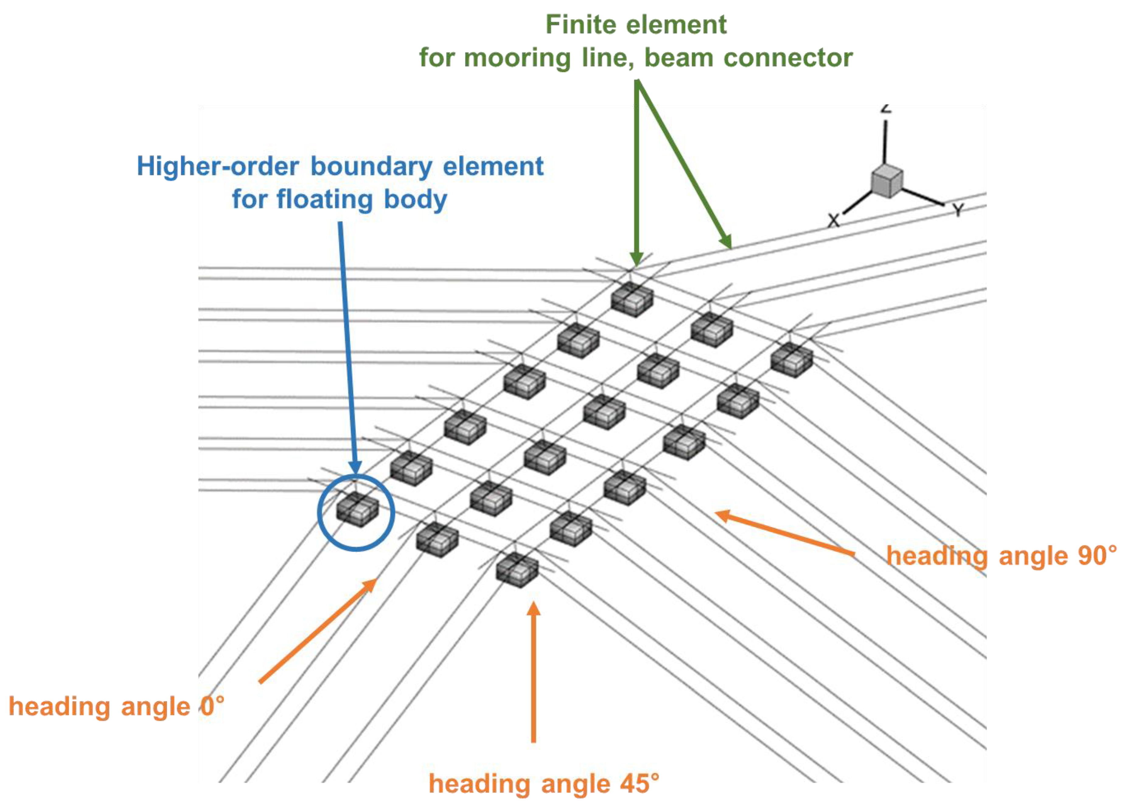
3.1. Fluid-Structure Interaction Numerical Analysis for DBM

The motion and structural analysis of the multi-linked floating offshore structure presented in Table 1 was performed using the in-house code of the Korea Research Institute of Ships & Ocean Engineering (KRISO) [16]. The wave load acting on the structure and the hydrodynamic properties along the wave load condition presented in Table 2 were calculated through a motion analysis based on the higher-order boundary element method and converted into time series through convolution transformation [17,18]. The converted results of the motion analysis were transferred to a finite element model as shown in Figure 2 for a structural analysis and used as the load conditions for performing a time-series finite element analysis. The numerical model for the motion analysis was built with 432 9-node higher-order boundary elements. For the structural analysis, the wave load acting on the surface of the floating body, calculated from the motion analysis, was integrated and made equivalent to a single node on a finite element. To eliminate energy loss therefrom, four beam elements with infinite stiffness were linked to each node. The wave load acting on a floating body is transferred to the beam structural members through the beam elements. Using the bending stress of each beam element calculated through the numerical analysis, the principal DBMs of the multi-linked floating offshore structure were selected through the DBM selection algorithm, and the conversion matrix was finally calculated.

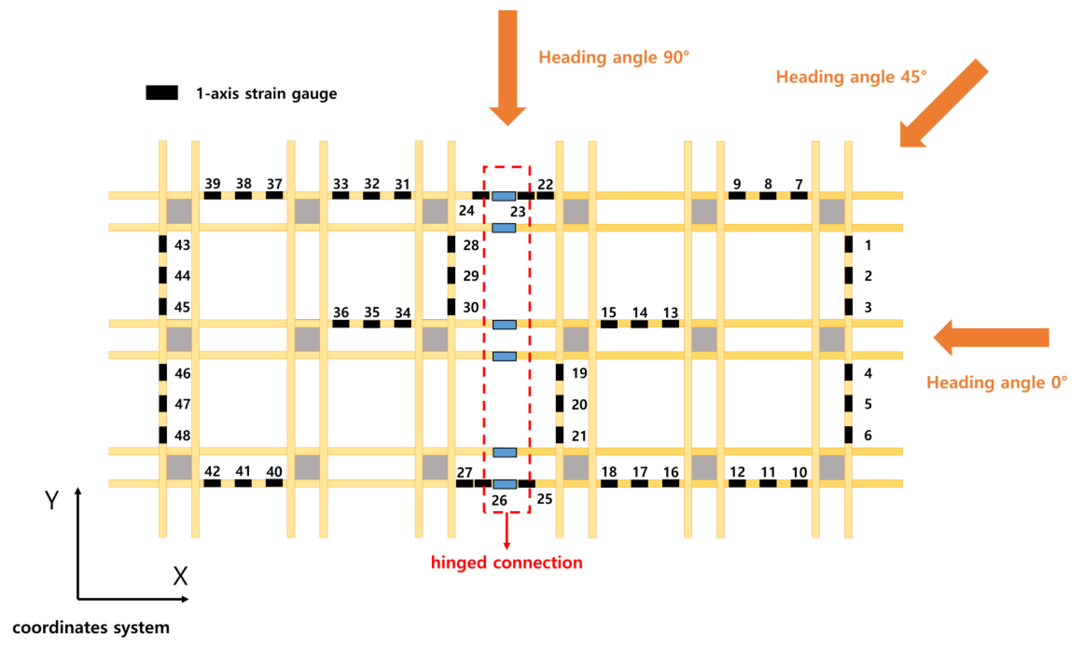
3.2. Model Experiment for Multi-Linked Floating Offshore Structure

A model experiment was performed to measure and analyze the motion and structural response of the multi-linked floating offshore structure. The model experiment was performed in the ocean engineering basin at the KRISO, as shown in Figure 3. Subsequently, the six degrees-of-freedom motion, the mooring tension, and the bending stress of the beam connectors were measured as shown in Table 3. Table 4 presents the wave load condition of model test. Afterwards, a data analysis was carried out to obtain the bending stress data to be used in the DBM conversion matrix.

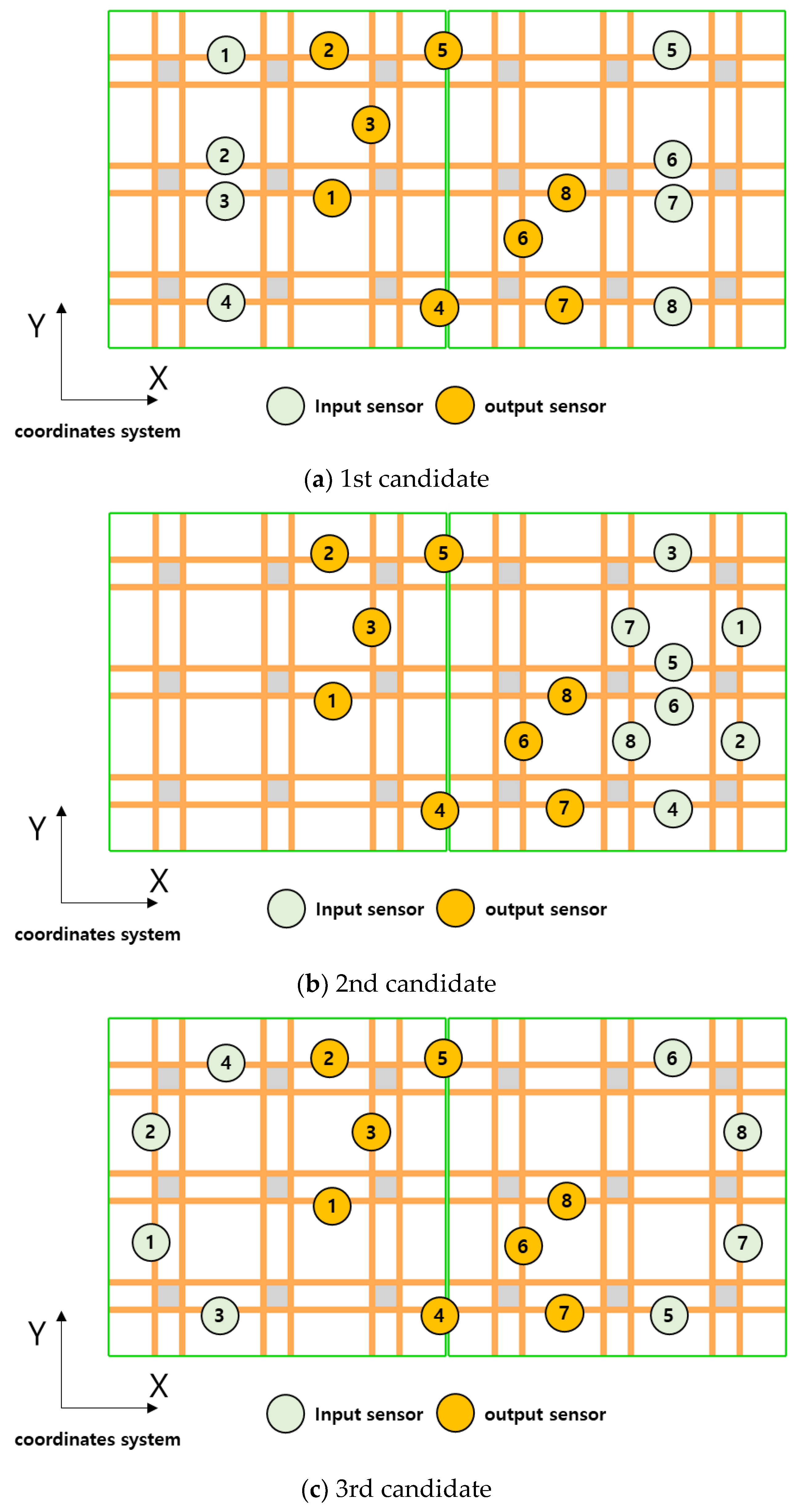
3.3. Setting of Input and Output Elements for DBM Conversion Matrix

The prediction of the structural responses of the multi-linked floating offshore structure was carried out based on the measurement results of the bending stress obtained through the model experiment. Therefore, the structural responses corresponding to the input and output of the DBM conversion matrix were set to be the bending stress measured through the sensors installed on the model. A total of 48 uniaxial strain sensors were installed on the model at the positions shown in Figure 4. As sensors are unable to measure the structural response of the entire beam structural members, the sensor positions were determined in consideration of the symmetry of the structure and the positions where a large bending stress occurred.
To analyze the effect of the DBM conversion matrix on the input and output, as shown in Figure 5, the bending stress at the sensors corresponding to the output was set to be equal, and the positions of the sensors corresponding to the input were divided into three input sensor candidate groups, thereby comparing the predicted structural responses for each candidate group. The first candidate group was a set of sensors installed on the structural members of which cross-sectional direction was the same as the propagation direction of the bow sea (0°). The second candidate group was a set of sensors installed on the structural members, among the structural members of the unit structure described above, of which the cross-sectional direction was the same as or perpendicular to the propagation direction of the bow wave. The third candidate group was a set of sensors installed on the outer structural members of the structure where a large bending stress occurred. In the present study, we performed both the prediction of the structural response based on the results of the numerical analysis and the prediction of the structural response based on the results of the model experiment for each of the candidate groups, and analyzed the results from each prediction to investigate the conversion matrix characteristics of the multi-linked floating offshore structure with hinged connection.

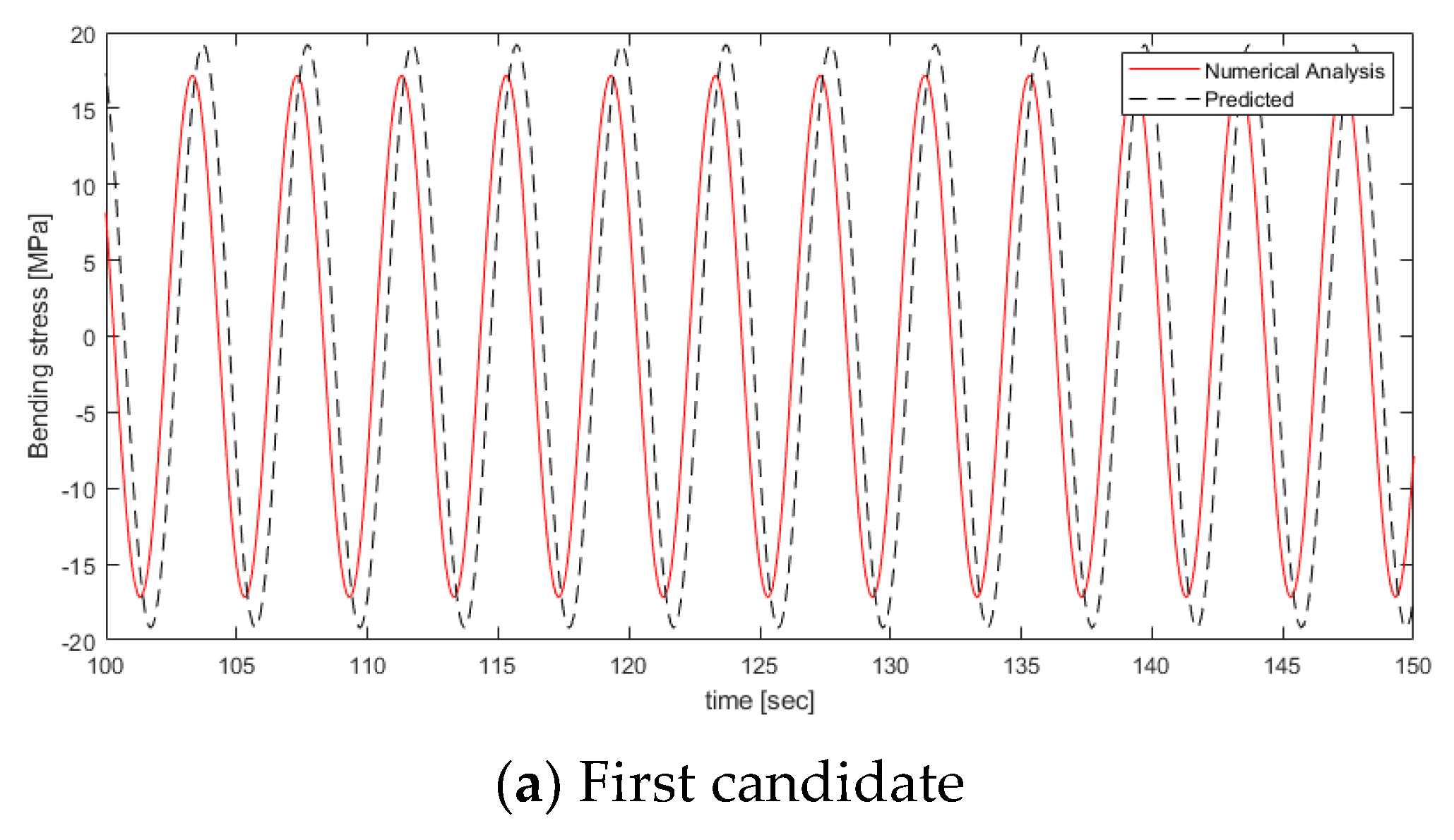
3.4. Predicted Bending Stress through DBM Conversion Matrix

To calculate the conversion matrix for the three input sensor candidate groups, 20 principal DBMs for each candidate group were extracted, as shown in Table 5. The importance of the selected principal DBMs is determined according to the sequence, and thus the first DBM is considered as the most important DBM. The first DBM is calculated as the autocorrelation coefficient between the bending stresses at the sensor position used for the input generated in the same phase. From the second DBM, DBMs that are orthogonal to the previously selected DBMs are extracted. As a result of extracting the principal DBMs for the three candidate groups, the first principal DBM for all the three candidate groups was determined as a wave load condition having an oblique sea (45°) and period of 4.5 s with the maximum bending stress. However, from the second principal DBM, the principal DBMs were all different among the candidate groups, because the structural members of each sensor candidate groups have different structural characteristics. The principal DBMs of the first input sensor candidate group were selected only under the wave load conditions of the head sea and the oblique sea but not under the wave load conditions of the beam sea. This was because, under the beam sea conditions, a large bending stress is not incurred at a structural member of which cross-sectional direction is perpendicular to the propagation direction of the beam sea (90°). For the second and third input sensor candidate groups, the DBMs were selected under the three wave direction conditions, but the proportions of the wave load conditions of the wave directions were different in the principal DBMs. The wave load conditions with heading angle 0° had the largest proportion in the second input sensor candidate group, while the wave load conditions with heading angle 45° had the largest proportion in the third input sensor candidate group.
Figure 6 shows the predicted structural response of each of the input sensor candidate groups based on the results of the numerical analysis. The input data was performed with respect to the bending stress under the regular wave conditions of the three wave directions that were not included in the principal DBMs. The accuracy of structural response prediction was quantified by defining the mean relative error between the bending stress predicted through the conversion matrix and the bending stress obtained from the numerical analysis. The results of the prediction of the structural responses of the individual candidate groups showed that the errors of the conversion matrix of the first input sensor candidate group were 1.4%, 3.7%, and 10.2% for the wave load with heading angle 0°, 45°, and 90°, respectively, indicating that the bending stress prediction accuracy was highest under the wave load conditions with heading angle ° and lowest under the wave conditions with heading angle 90°. As shown in Figure 6, the error with wave load conditions with heading angle 45° and wave period 6.0 s was large because not only the predicted value of the bending stress was different from the results of the numerical analysis but also there was a phase difference which was 1/3 the period or larger. In the second input sensor candidate group, the mean relative error was 3.2%, 4.5%, and 1.6% for the respective wave conditions, indicating that the bending stress prediction accuracy was highest, which was opposite to the first candidate group. In the third input sensor candidate group, the mean relative error was 1.3%, 1.2%, and 1.8% for the respective wave conditions, indicating that the bending stress prediction accuracy was highest among the three candidate groups. Figure 6 shows that the bending stress was predicted in the same phase as the results of the numerical analysis for the three types of regular waves. The comparison of the bending stress prediction accuracy among the input sensor candidate groups confirmed that the results of the bending stress prediction were different among the three candidate groups, which may be because of the principal DBMs included in the conversion matrix of each candidate group. The first candidate group was composed of only the structural members of which cross-sectional direction is the same as the propagation direction of the bow sea, and the structural members have a large bending stress under the bow sea and oblique sea conditions and a relatively small bending stress under the beam sea conditions. As these structural characteristics are reflected, the DBMs constituting the conversion matrix were mainly those for the bow sea conditions. Therefore, the prediction accuracy was low under the wave load conditions with heading angle 90° for which no principal DBMs were present. In the second and third candidate groups, the conversion matrix included the principal DBMs for the three wave directions, but the bending stress prediction accuracy was different. To compare the principal DBMs of the input and output structural responses of the conversion matrix, we extracted the principal DBMs of the structural members corresponding to the output of the conversion matrix as illustrated in Table 6. The comparison showed that the results of the principal DBM selection for the output elements were similar to the results of the principal DBM selection for the third candidate group. Therefore, the bending stress at different output positions was expressed most accurately with the principal DBMs constituting the conversion matrix of the third input sensor candidate group, as indicated by the highest bending stress prediction accuracy of the third candidate group.
After comparing the results of the numerical analysis, we analyzed the prediction results based on the model experiment results for each of the input sensor candidate groups. Figure 7 shows the results of the bending stress prediction for each of the input sensor candidate groups based on the model experiment results. The overall bending stress prediction accuracy was lower than the prediction accuracy of the results of the numerical analysis, and notably, there was a slight phase difference with the results of the model experiment. This may be because the structural characteristics of the model were changed due to the limitations in constructing an ideal model. Based on the finding that the mean relative error was largest in the second candidate group composed of only the structural members of a single unit structure. It was analyzed that the motion response characteristics of the actual model changed due to the hinge connection, and as a result, the structural response was out of phase with the numerical analysis. The comparison between the results of the numerical analysis and the results of the model experiment showed a phase difference in the structural response between the front unit structure and the rear one. So, the phase difference in structural response between the numerical analysis and model test was calculated and the phase difference was corrected by shifting it. Furthermore, the high-frequency components and the noise components of the measurement data obtained from the model experiment may have affected the performance of conversion matrix response because it is mixed with the small structural response, thereby increasing the mean relative error. Therefore, in this study, band-pass filtering was applied to remove frequency components above 10 Hz.
The DBM-based bending stress prediction results for the model test are shown in Figure 8 and Figure 9. Figure 8 shows the measured bending stress values over time for sensors 1, 2, and 3 at the output location and the predicted values through the conversion matrix with third sensor candidate group. The predicted results were shifted according to the measured signal to compensate for the phase difference. Figure 9 represents the bending stress RAO (response amplitude operator) for the measured of sensors 1, 2, and 3 and predicted results with conversion matrix of third candidate group according to each heading angle of wave load. Among the predicted bending stress RAOs, the accuracy for the wave load condition with heading angle 45° shows the highest accuracy, because the DBMs for the heading angle 45° were of high importance among DBMs. The bending stress prediction based on the results of the model experiment through the DBM conversion matrix had a larger mean relative error than that of the results of the numerical analysis as illustrated in Figure 10. The prediction accuracy errors for the experimental results average 7%, 4%, and 1%, respectively, and the trends are the same as those in the numerical analysis. There are two main reasons why the error has increased. The first cause is analyzed to be due to the nonlinearity of waves and signal noise. Unlike numerical analysis that assumes linearity, in the case of model testing, nonlinear wave loads such as green water and wave impact may be applied, and DBM techniques based on numerical analysis have limitations in predicting these. The second one may be because of the change of the structural characteristics of the model, which was constructed to be different from the ideal numerical model.

4. Conclusions

In this study, we performed the prediction of structural responses of a multi-linked floating offshore structure using a DBM-based conversion matrix. The principal DBMs of the structure were selected based on the results of the fluid–structure interaction numerical analysis, and the structural responses were predicted by the conversion matrix based on the results of a model experiment. In addition, we generated three different combinations of the sensor positions corresponding to the inputs of the conversion matrix, and comparatively analyzed the results of the structural response prediction for each sensor candidate group. From the results, we acquired the following conclusions.
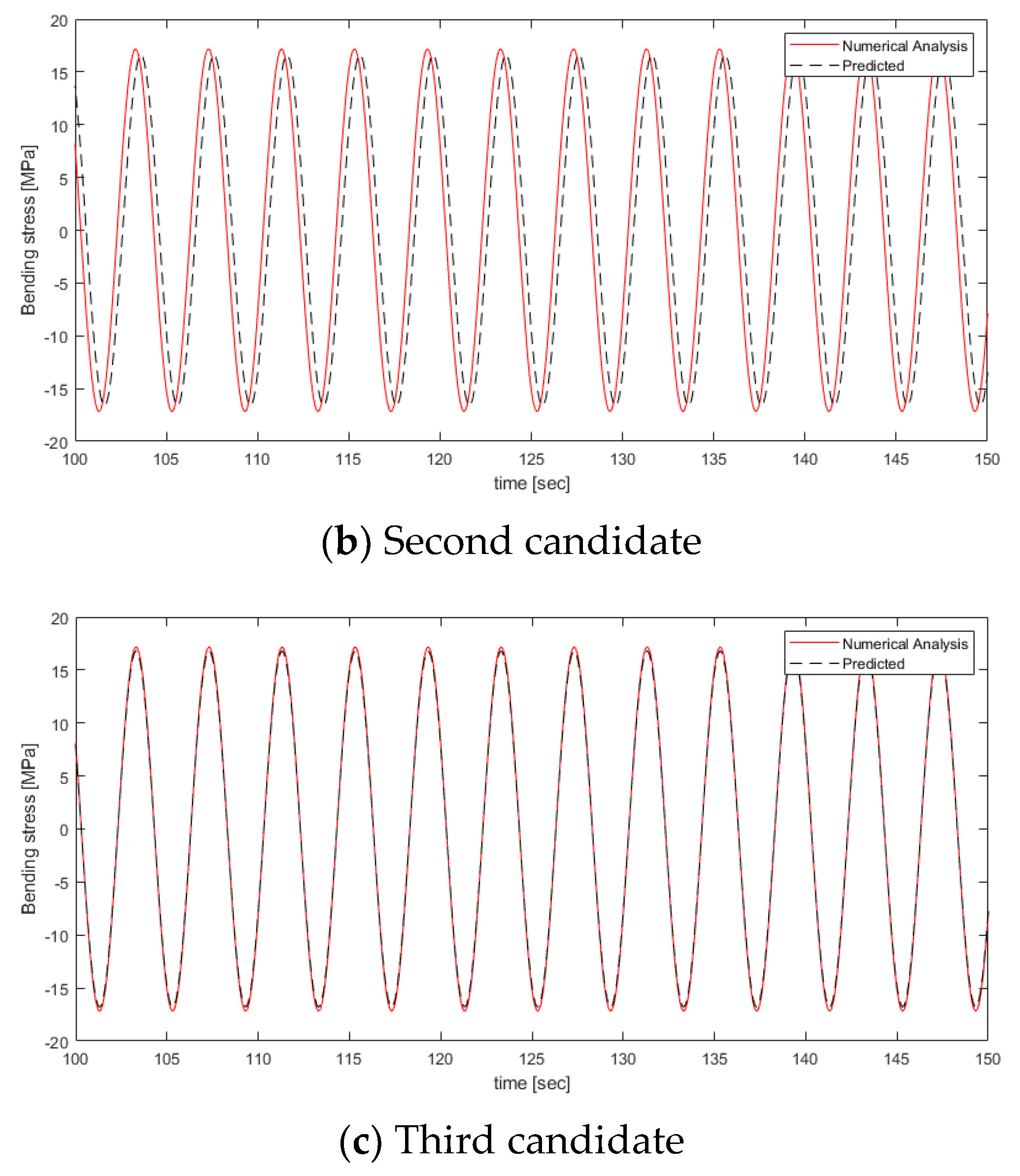
  • The DBM-based structural response prediction method was applied to a multi-linked floating offshore structure. Based on the results of the fluid–structure interaction numerical analysis, the conversion matrix was calculated through the principal DBM selection algorithm. The structural response prediction accuracy was evaluated for three candidate groups by varying the sensor positions of the structural members corresponding to the inputs of the conversion matrix, and the evaluation showed that the results of the structural responses were different among the three groups. This indicated that the DBM-based conversion matrix of the multi-linked floating offshore structure was affected by the selection of the sensor positions. The first to fourth modes among the DBMs of the third group and the DBMs of the output sensor are the same. The structural response prediction accuracy was high when the principal DBMs of the structural members at the input positions were similar to the DBMs of the structural members at the output positions.
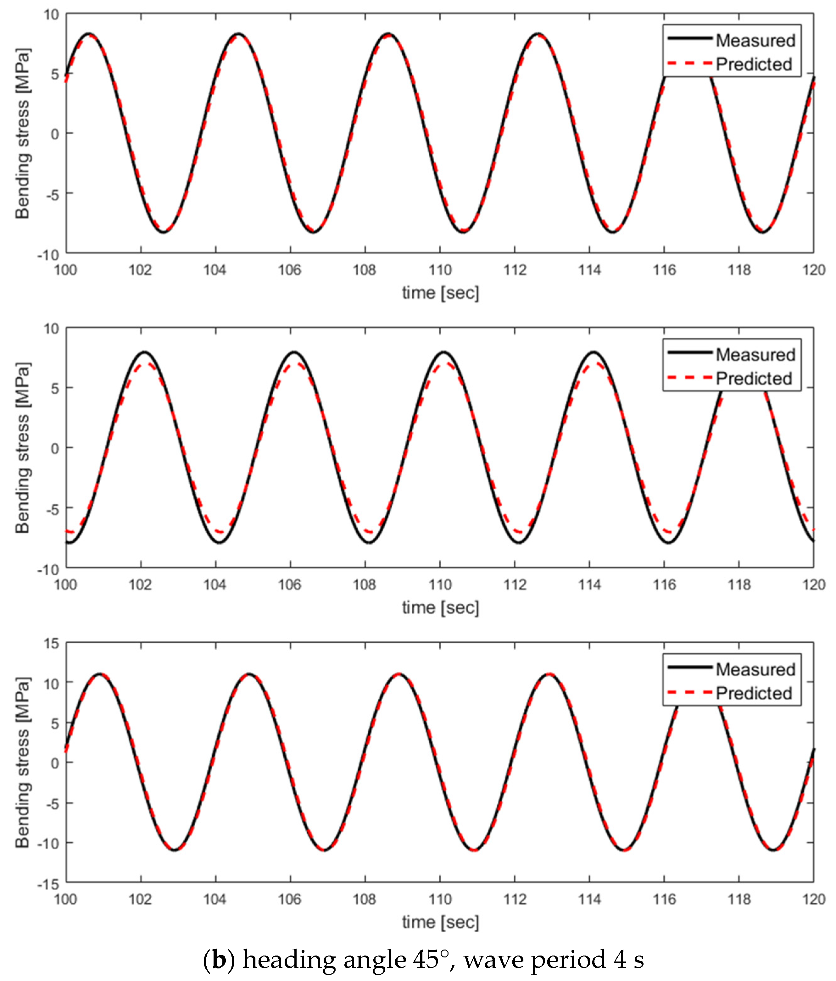
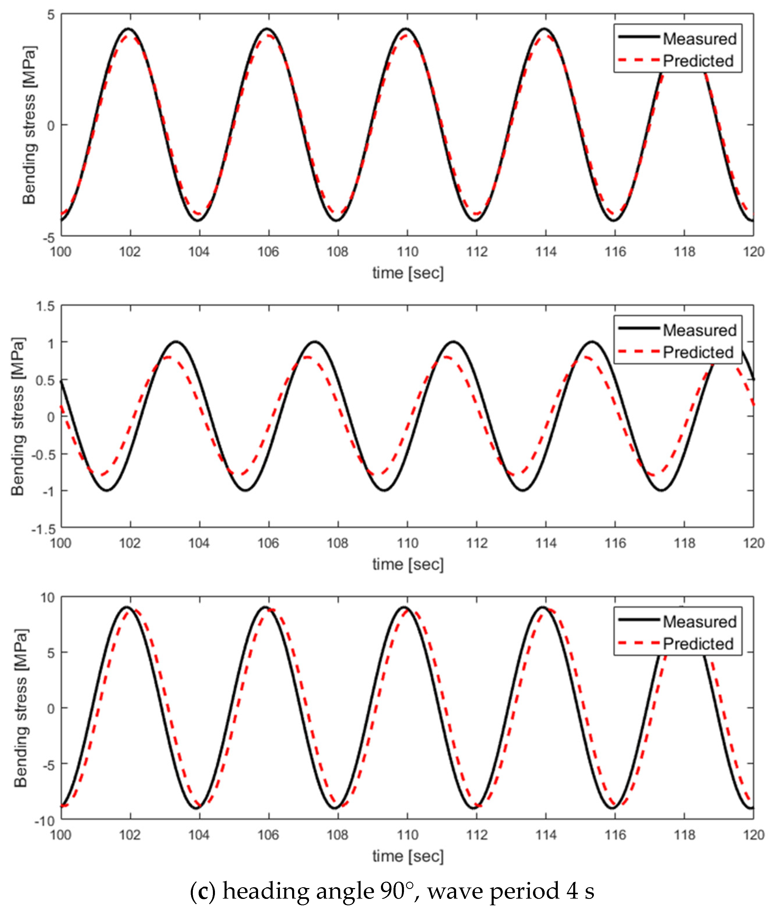
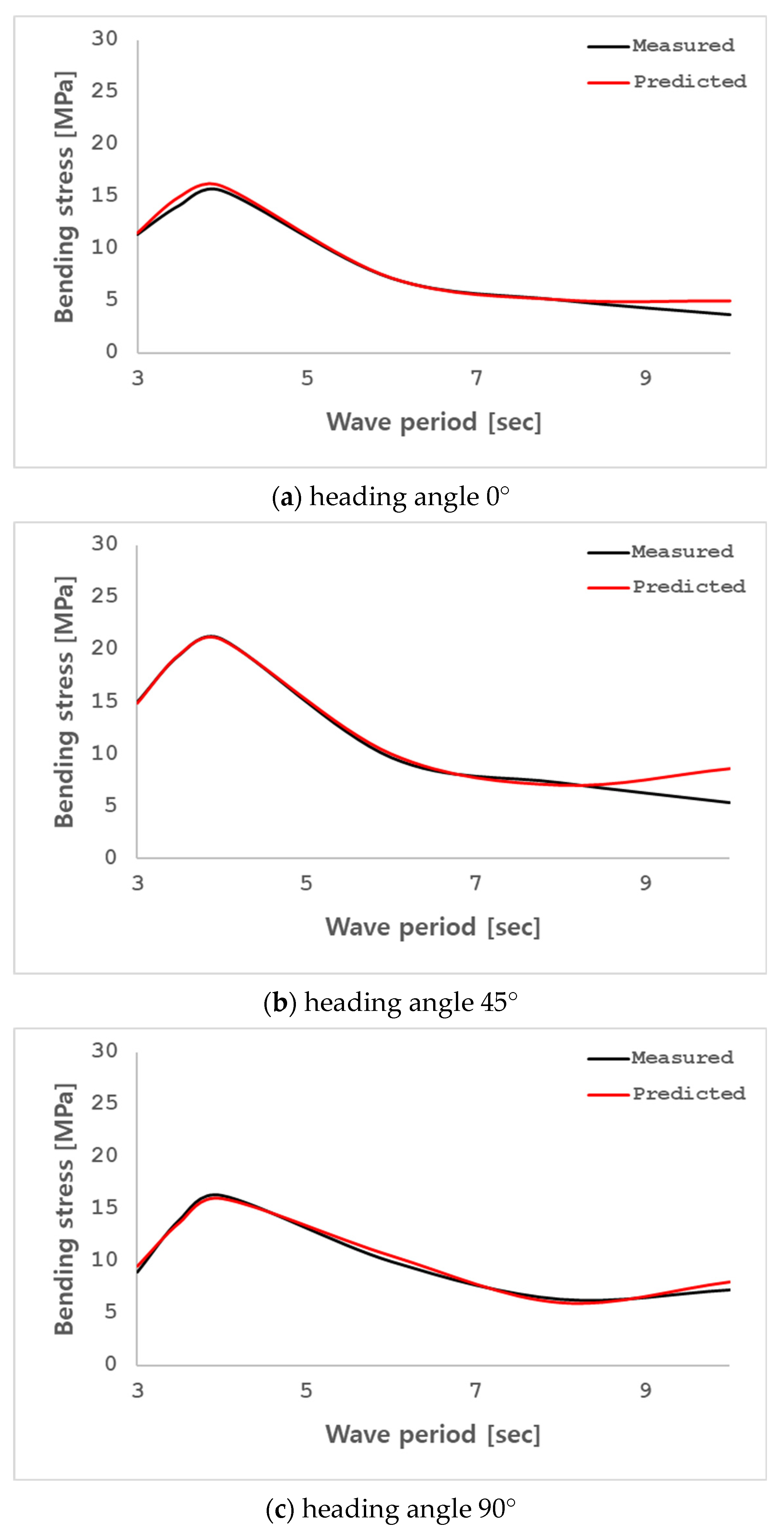
  • We analyzed the bending stress prediction results obtained through the conversion matrix based on the results of the numerical analysis and model test. The first candidate group lacked the DBMs for the wave condition with heading angle 45° and exhibited the lowest bending stress prediction accuracy for the wave condition with heading angle 45°. The second and third candidate groups are composed of the DBMs for the wave condition with heading angle 0°, 45°, 90°, but the second candidate group had a phase difference for all the bending stress prediction results and exhibited a lower bending stress prediction accuracy. The third candidate group showed a high bending stress prediction accuracy with an error of about 1%, indicating that the principal DBMs constituting the conversion matrix of the third candidate group reflect the DBMs constituting the bending stress at the output positions. Therefore, to achieve a high prediction accuracy for bending stress under various wave conditions, the principal DBMs for the structural members at the input positions should be composed of regular waves of various directions and periods. In addition, it is important to select DBMs for the output structural responses to determine the sensor positions of the most similar DBMs.
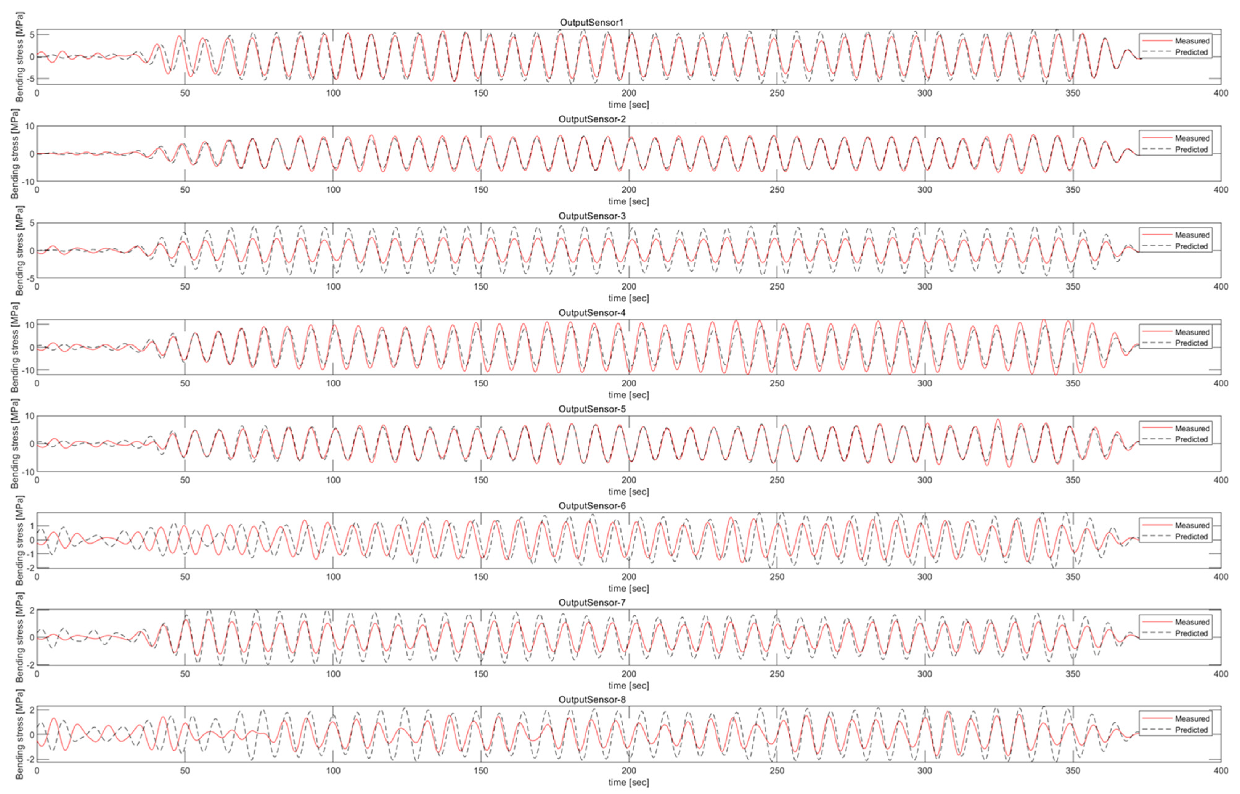
  • The prediction error for model test may have been incurred because the principal DBMs of the conversion matrix were prepared based on the results of the numerical analysis. The application of phase difference compensation to the prediction results brought out results that were almost the same as the measurement results. As such, an actual structure may have structural characteristics that are different from its numerical model. Therefore, it is necessary to confirm the similarity of the structural responses of an actual structure in comparison with the results of the numerical analysis. Further studies may need to be conducted to compensate the bending stress prediction method by reflecting the structure characteristics of an actual structure that may be changed from its numerical model [19].
To perform real-time structural health monitoring using digital twins, it is necessary to be able to output a structural response with a certain level of accuracy or higher within a short time [20,21,22]. In this study, a DBM-based order reduction method was used to derive a conversion matrix that predicts the structural response for multi-linked floating offshore structure with a mean relative error 1%. In addition, through comparison of prediction accuracy according to sensor locations, a conversion matrix with similar DBM between input and output was derived by considering the structural characteristics of the structure. As a result of comparison with the model test, it was confirmed that the prediction accuracy was reduced due to the different characteristics from the numerical model. Despite these limitations, the DBM-based order reduction method can potentially be used as an effective tool for predicting the structural responses, providing a basis for the introduction for digital twins for structural health monitoring. In the future, to develop the order reduction method, we plan to conduct research on optimized sensor locations and prediction accuracy performance using advanced optimization techniques such as machine learning.

Author Contributions

Conceptualization, K.L.; Methodology, K.S. and K.L.; Model test, K.S. and K.L.; Data curation, K.L.; Validation, K.L.; Formal analysis, K.S. and K.L.; Visualization, K.S. and K.L.; Writing—original draft preparation and editing, K.S.; Writing—review and editing, K.L. All authors have read and agreed to the published version of the manuscript.

Funding

This research was supported by the Endowment Project of “Core Technology Development of Hydro-elasticity based Structural Damage Assessment for Offshore Structures considering Uncertainty (4/5)” funded by the Korea Research Institute of Ships and Ocean Engineering (PES4770) and this work was supported by the Shipbuilding & Marine Industry Technology Development Program (20024292, Development of Digital Twin System for Health Management of Hull based on Marine Environment and Hull Response Measurement Data) funded By the Ministry of Trade, Industry & Energy (MOTIE, Republic of Korea).

Institutional Review Board Statement

Not applicable.

Informed Consent Statement

Not applicable.

Data Availability Statement

Data are contained within the article.

Conflicts of Interest

The authors declare no conflict of interest.

References

  1. Moore, E.H. On the Reciprocal of the General Algebraic Matrix. Bull. Am. Math. Soc. 1920, 26, 394–395. [Google Scholar]
  2. Bjerhammar, A. Application of Calculus of Matrices to Method of Least Squares: With Special References to Geodetic Calculations. Trans. Roy. Inst. Technol. Stockh. 1951, 49, 1–86. [Google Scholar]
  3. Penrose, R. A Generalized Inverse for Matrices. Proc. Camb. Philos. Soc. 1955, 51, 406–413. [Google Scholar] [CrossRef]
  4. Baudin, E.; Bigot, F.; Derbanne, Q.; Sireta, F.X.; Quinton, E. Increasing ULCS Structural Response Knowledge Through 3DFEM and a Comprehensive Full-Scale Measurement System. In Proceedings of the Twenty-Third International Offshore and Polar Engineering, Anchorage, AK, USA, 30 June–5 July 2013; pp. 56–62. [Google Scholar]
  5. Bigot, F.; Derbanne, Q.; Baudin, E. A Review of Strains to Internal Loads Conversion Methods in Full Scale Measurements. In Proceedings of the PRADS2013, Changwon, Republic of Korea, 20–25 October 2013; pp. 259–266. [Google Scholar]
  6. Bigot, F.; Sireta, F.X.; Baudin, E.; Derbanne, Q.; Tiphine, E.; Malenica, S. A Novel Solution to Compute Stress Time Series in Nonlinear Hydro-Structure Simulation. In Proceedings of the ASME 2015 34th International Conference on Ocean, Offshore and Arctic Engineering, St. John’s, NL, Canada, 31 May–5 June 2015; pp. 1–11. [Google Scholar]
  7. Kefal, A.; Mayang, J.B.; Oterkus, E.; Yildiz, M. Three Dimensional Shape and Stress monitoring of Bulk Carriers based on iFEM Methodology. Ocean Eng. 2017, 147, 256–267. [Google Scholar] [CrossRef]
  8. Kefal, A.; Tessler, A.; Oterkus, E. An Enhanced Inverse Finite Element Method for Displacement and Stress Monitoring of Multilayered Composite and Sandwich Structures. Compos. Struct. 2017, 179, 514–540. [Google Scholar] [CrossRef]
  9. Kobayashi, M.; Jumonji, T.; Murayama, H. Three-Dimensional Shape Sensing by Inverse Finite Element Method based on Distributed Fiber-optic Sensors. In Practical Design of Ships and Other Floating Structures: Proceedings of the 14th International Symposium, Yokohama, Japan, 22–26 September 2019; Springer: Berlin/Heidelberg, Germany, 2019; Volume 64, pp. 40–48. [Google Scholar]
  10. Han, J.S.; Kim, S.H. Automation of Krylov Subspace Model Order Reduction for Transient Response Analysis with Multiple Loading. J. Comput. Struct. Eng. Inst. Korea 2021, 34, 101–111. [Google Scholar] [CrossRef]
  11. Lai, X.; Yang, L.; He, X.; Pang, Y.; Song, X. Digital Twin-based Structural Health Monitoring by Combining Measurement and Computational data: An Aircraft Wing Example. J. Manuf. Syst. 2023, 69, 76–90. [Google Scholar] [CrossRef]
  12. Barhoumi, M.; Storhaug, G. Assessment of Whipping and Springing on a Large Container Vessel. Int. J. Nav. Archit. Ocean Eng. 2014, 6, 442–458. [Google Scholar] [CrossRef]
  13. Ho, Y.; Song, L.; Liu, Z.; Yao, J. Identification of ship hydrodynamic derivatives based on LS-SVM with wavelet threshold denoising. J. Mar. Sci. Eng. 2021, 9, 1356. [Google Scholar]
  14. Son, H.-Y.; Kim, G.Y.; Kang, H.-J.; Choi, J.C.; Lee, D.-K.; Shin, S.-C. Ship Motion-Based Prediction of Damage Locations Using Bidirectional Long Short-Term Memory. J. Ocean Eng. Technol. 2022, 36, 295–302. [Google Scholar] [CrossRef]
  15. Vu, H.T.; Park, J.; Yoon, H.K. Estimating Hydrodynamic Coefficients of Real Ships Using AIS Data and Support Vector Regression. J. Ocean Eng. Technol. 2023, 37, 198–204. [Google Scholar] [CrossRef]
  16. Sim, K.; Lee, K.; Kim, B.W. Structural Response Analysis for Multi-Linked Floating Offshore Structure Based on Fluid-Structure Coupled Analysis. J. Ocean Eng. Technol. 2023, 37, 273–281. [Google Scholar] [CrossRef]
  17. Kim, B.W.; Hong, S.Y.; Sung, H.G. Comparison of Drift Force Calculation Methods in Time Domain Analysis of Moored Bodies. Ocean Eng. 2016, 126, 81–91. [Google Scholar] [CrossRef]
  18. Kim, B.W.; Hong, S.Y.; Kyoung, J.H.; Cho, S.K. Evaluation of Bending Moments and Shear Forces at Unit Connections of Very Large Floating Structures Using Hydroelastic and Rigid Body Analyses. Ocean Eng. 2006, 34, 1668–1679. [Google Scholar] [CrossRef]
  19. Kim, H.S.; Kim, B.W.; Lee, K.; Sung, H.G. Application of Average Sea-state Method for Fast Estimation of Fatigue Damage of Offshore Structure in Waves with Various Distribution Types of Occurrence Probability. Ocean Eng. 2022, 246, 110601. [Google Scholar] [CrossRef]
  20. Schirmann, M.L.; Chen, T.; Collette, M.D.; Gose, J.W. Linking Seakeeping Performance Predictions with Onboard Measurements for Surface Platform Digital Twins. In Proceedings of the 14th International Symposium on Practical Design of Ships and Other Floating Structures, Yokohama, Japan, 22–26 September 2019. [Google Scholar]
  21. Tygesen, U.T.; Jepsen, M.S.; Vestermark, J.; Dollerup, N.; Perdersen, A. The True Digital Twin Concept for Fatigue Reassessment of Marine Structures. In Proceedings of the 14th International Symposium on Practical Design of Ships and Other Floating Structures, Yokohama, Japan, 22–26 September 2019. [Google Scholar]
  22. Kim, C.H. A Study for Digital Transformation Based on Collaboration Master Plan for Shipbuilding & Marine Engineering Industry. J. Ocean Eng. Technol. 2022, 37, 190–197. [Google Scholar]
Figure 1. Flow chart for DBM selection algorithm.
Jmse 12 00262 g001
Figure 2. Structural models of multi-linked floating offshore structures module (Sim et al., 2023 [16]).
Jmse 12 00262 g002
Figure 3. Installation for model test.
Jmse 12 00262 g003
Figure 4. Sensor arrangement on the model.
Jmse 12 00262 g004
Figure 5. Sensor location sets for input and output structural response. (a) a set of sensors installed on the structural members of which cross-sectional direction. (b) a set of sensors installed on the structural members, among the structural members of the unit structure described above, of which cross-sectional direction was the same as or perpendicular to the propagation direction of the bow sea. (c) a set of sensors installed on the outer structural members of the structure where a large bending stress occurred.
Jmse 12 00262 g005
Figure 6. Prediction of bending stress of output sensor 1 for wave load condition (heading angle 45°, wave period 6.0 s). (a) time series bending stress of output sensor 1 in 1st candidate group. (b) time series bending stress of output sensor 1 in 2nd candidate group. (c) time series bending stress of output sensor 1 in 3rd candidate group.
Jmse 12 00262 g006aJmse 12 00262 g006b
Figure 7. Comparison of measured and predicted bending stress for sensors at 8 output positions.
Jmse 12 00262 g007
Figure 8. Prediction of bending stress time series of output sensor 1, 2, 3 for third sensor candidate group. (a) wave load conditions with heading angle 0° and wave period 4 s. (b) wave load conditions with heading angle 45° and wave period 4 s. (c) wave load conditions with heading angle 90° and wave period 4 s.
Jmse 12 00262 g008aJmse 12 00262 g008bJmse 12 00262 g008c
Figure 9. Bending stress RAO for output sensor 1, 2, 3 for third sensor candidate group. (a) wave load conditions with heading angle 0°. (b) wave load conditions with heading angle 45°. (c) wave load conditions with heading angle 90°.
Jmse 12 00262 g009
Figure 10. Relative Error of bending stress prediction for three candidate groups.
Jmse 12 00262 g010
Table 1. Principal dimension of multi-linked floating offshore structure.
Principal Dimension
Dimension [m]B × L × Draft = 18 × 36 × 1.005
Total Mass [kg]30,041
MaterialAluminum
Dimension of floating body [m]B × L × H = 1.8 × 1.8 × 1.72
Center of gravity [m]0.634 m
Center of buoyancy [m]−0.503 m
Dimension of beam connectorB × L × t1 × t2 = 0.34 × 0.38 × 0.03 × 0.03
Elastic modulus of beam connector [GPa]69.60
Spring constant of mooring line [N/m]62,336.97
Table 2. Case of numerical analysis under wave load condition.
Wave Load Case
Heading angle [°]0:15:90
Wave period [s]3.0, 3.5, 4.0, 4.5, 5.0, 5.5, 6.0, 6.5, 8.0, 10.0
Table 3. Measurement items.
Measured ItemSensorDAQ SystemNo. Channels
6 DOF motionsStructure in frontOptical LEDRODYM-6D6
Structure behindOptical LEDRODYM-6D6
Stress on connector beamBending stress1-axis strain gaugeNI system48
Shear stress2-axis Rosette gaugeNI system4
Tension on mooring lineTensionLoadcellNI system4
Irregular waveIRR-01Capacitance probeNI system1
Table 4. Wave load condition.
TypeHeading Angle [°]Wave Height/Significant Wave Height [m]Wave Period/Modal Period [s]
Regular wave0, 45, 900.3513.00
0.4783.50
0.6244.00
0.7904.50
0.9765.00
1.0005.50
1.0006.00
1.0008.00
1.00010.00
Irregular wave0, 45, 901.0004.00
1.0006.00
0.8004.00
0.8006.00
Table 5. Results of the principal DBM selection for three candidate groups of input sensor.
DBMWave Load Case
(Heading Angle/Wave Period)
1st Candidate Groups2nd Candidate Groups3rd Candidate Groups
1st mode45°/4.5 s45°/4.5 s45°/4.5 s
2nd mode45°/4.0 s45°/4.0 s0°/5.0 s
3rd mode0°/5.5 s0°/3.5 s45°/5.5 s
4th mode90°/3.5 s90°/4.0 s0°/3.5 s
5th mode0°/5.0 s0°/6.0 s90°/5.5 s
Table 6. Principal DBMs of structural members corresponding to conversion matrix outputs.
DBM of Output SensorsWave Load Case
(Heading Angle/Wave Period)
First mode45°/4.5 s
Second mode45°/5.5 s
Third mode0°/5.0 s
Fourth mode0°/3.5 s
Fifth mode90°/5.0 s
Disclaimer/Publisher’s Note: The statements, opinions and data contained in all publications are solely those of the individual author(s) and contributor(s) and not of MDPI and/or the editor(s). MDPI and/or the editor(s) disclaim responsibility for any injury to people or property resulting from any ideas, methods, instructions or products referred to in the content.

