1. Introduction
The maritime industry acts as a pioneer industry with a high sense of responsibility to combat climate change and adapt to the consequences of its adverse effects. In this context, the International Maritime Organization’s goal of reducing at least 50% greenhouse gas emissions from ships on a global scale by 2050 [
1] and the legal regulations that come into force with it have effects that change the face of the maritime industry as a whole in many areas, from the optimization of ship forms to new propulsion systems, from the use of new fuels to the lightening of ship structures [
2,
3,
4].
Within the scope of the studies on lightening ships for more sustainable sea transportation, starting from the topological optimization of their design, the direction is towards materials with high specific strength, i.e., new and lighter manufacturing methods. In addition to the preference for light metals such as aluminum and magnesium alloys, fiber-reinforced polymer-based composites (FRPs) have become the primary construction material [
5], especially in relatively small-sized ships that are mass-produced, due to their high durability against the corrosive effects of the marine environment, the freedom they provide to the boat designer to act in creating forms, and their resistance to loads that are felt more strongly, especially in high-sea weather, such as fatigue and impact.
To improve sustainability, efforts to lighten a newly constructed ship as a whole and partially lighten only some components of a newly built or existing ship are meaningful. In this context, elements of the ship’s propulsion systems, such as rudders, propellers and shafts, ship superstructures, masts, and radar domes, are manufactured from FRPs in ships with steel hulls.
For instance, by producing propellers from FRPs, in addition to the possibility of benefiting from the positive aspects of these materials listed above, more flexible, improved vibration dumping properties, subject to lower bearing loads, and fewer misalignment problems will be achieved. QinetiQ in England has produced large-scale composite propellers for the Triton Trimaran, as has HDW in Germany for the German Navy, and, similarly, Airborne in the Netherlands for the Navy [
6]. Because propellers have the most complex geometries compared to other ship components to which new materials and manufacturing technologies can be adapted, success in their production will be a guide for different components. When the literature is examined, it is seen that since 2010, the optimization of the amounts of fiber and resin components, lamination sequences, and forms, including the thicknesses of composite propellers produced with conventional lamination methods such as hand lay-up, vacuum-assisted methods, and RTM, have been studied experimentally and theoretically [
7]. It is seen that their cost-effectiveness, corrosion resistance, and ease in manufacturing complex forms are emphasized [
8] as the reasons for using composite materials in propeller production, and the effect of blade deflections on the performance of propellers has also been studied frequently [
9,
10].
Additive manufacturing, which is an innovative manufacturing method using three-dimensional printers (3DAM), is widely used in industries such as automotives and aviation but has not yet received the attention it deserves in the maritime industry. Among the main techniques of 3DAM, which can be an ideal manufacturing method for parts with a complex form such as a ship propeller and produced as single/customized designs, the most common are material extrusion (MEX) [
11], stereolithography (SLA) and selective laser sintering (SLS) with powder bed fusion and binder-spraying [
12] standing out. Experimental development efforts have been intensively carried out on it since 2013 [
13]. 3DAM will be a serious manufacturing option for the maritime industry as printer technologies and sizes develop, with its features such as high production speed and precision and especially its affordable cost for small-scale production, rapid prototyping features for production, simplification of assemblies and reduction of number of joining and parts, compared to conventional manufacturing methods [
14,
15,
16,
17,
18,
19,
20,
21,
22]. Although the production of a complete ship propeller with 3DAM has yet to be completed to date, apart from experimental studies, studies on the production of aircraft wings produced with this method are increasing day by day. For example, Liang et al. [
23] and Shen and Mingtai [
24] presented the suitability of 3DAM for propeller blade production, accompanied by optimizing the hydrodynamic performance of propellers produced with this method. It has also been concluded that the use of lightweight materials in the manufacture of a ship propeller can enable the production of thicker yet flexible blades, thus increasing the cavitation inception speed and the hydrodynamic performance of that propeller [
25].
The general tendency in using polymer materials in propeller production is to lighten the structure, to be sustainable, to increase specific strength, to prevent vibration, and to provide corrosion resistance. The use of thermoplastics offers advantages for all these. The production of existing propeller designs with traditional production restricts design freedom. In this study, the performance analyses of the superiority of additive manufacturing in this sense were carried out. A 1/14 scale model of a ship propeller with a particular form was produced using a composite made of long glass, short carbon, and continuous carbon fiber-reinforced polyamide (PA)—also called ‘nylon’ in commercial terms—plastic, using 3DAM’s MEX technique, and an aluminum alloy, this time using 3DAM’s SLS technique.
While a traditional propeller material is made of metal, in this study, polymer was preferred for lightening. PA6 was also preferred because it is suitable for additive manufacturing and is an engineering polymer. PA6 has advantages in terms of superior mechanical properties, specific strength, chemical resistance, corrosion resistance, UV resistance, and workability.
The hydrodynamic performance of the propellers produced using 3DAM techniques from four different materials was comparatively examined by conducting cavitation tunnel tests, and the strength analysis was comparatively numerically examined with the help of data obtained from mechanical and physical tests, the details of which are given in the following section.
2. Materials and Methods
2.1. Ship Propeller Model
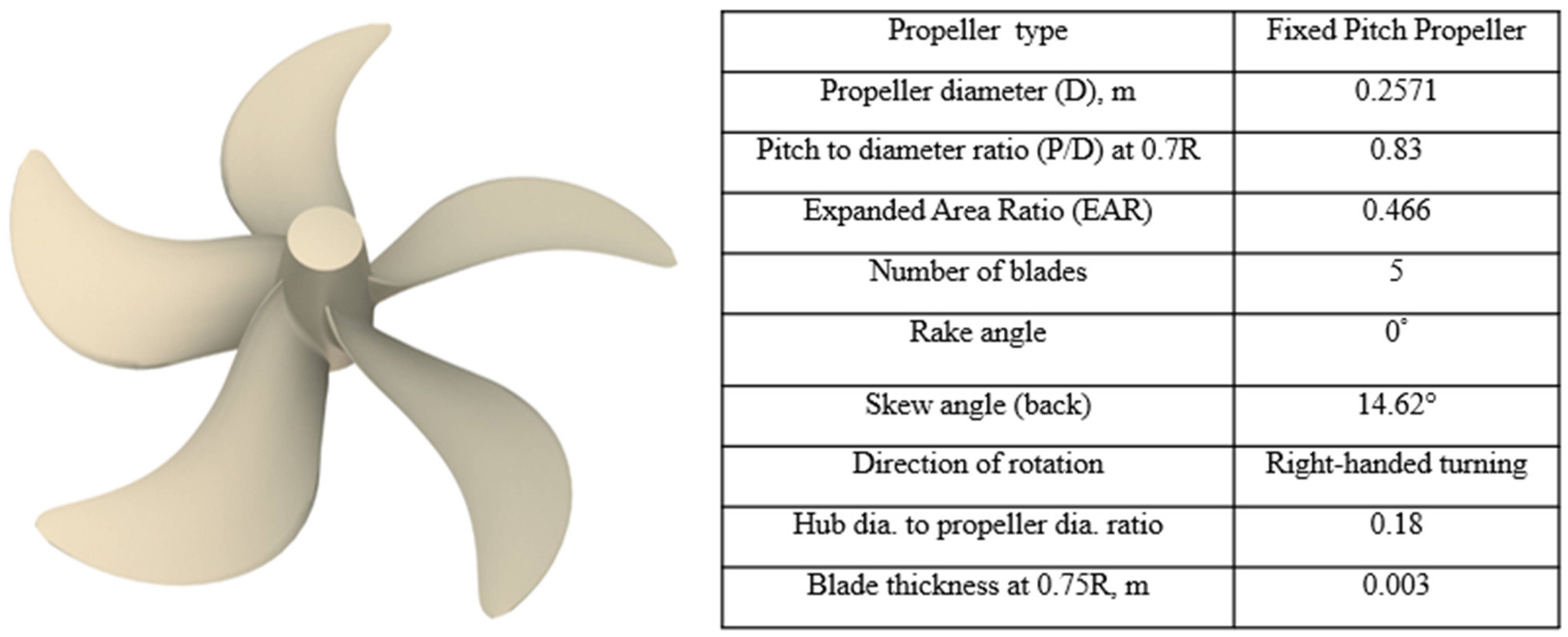
The propeller model used in this study has a unique geometry based on new propeller technology (NPT) and has already been installed on a bulk carrier with an overall length of 94 m equipped with a Gate Rudder
© [(Gate Rudder System as a Retrofit for the Next Generation Propulsion and Steering of Ships) project, EC H2020 Programme Initiative, Grant agreement no: 860337] system as a power-saving device [
4,
26], and outstanding propulsion efficiency was achieved. In this study, 1/14 scale models of the mentioned propeller produced with the 3DAM method were studied. Geometry and the specification of the propeller model is given in
Figure 1.
2.2. Materials and Additive Manufacturing Techniques Used in the Production of Propeller Models
The mechanical and physical properties of the propeller materials are presented in
Table 1.
Onyx
® in
Table 1 is a PA-based composite with a short carbon content of 10–20% by weight, produced in filament form by (Markforged, Waltham, MA, USA).
The mechanical properties of the composites from which the P2, P3, and P4 propellers were produced were obtained as a result of the tests carried out at the Dokuz Eylül University (İzmir/Türkiye) Engineering Faculty’s Composite Materials Laboratory with the help of the AGS-X model device (Shimadzu, Kyoto, Japan) following the relevant standards. Three samples were produced to find each mechanical property, and the appropriate tests were repeated three times, and the average of the obtained results is given in
Table 2. The density value in
Table 2 was obtained with the help of micro-CT analysis. These analyses were performed with the help of a μCT (Scanco, Brüttisellen, Switzerland) at Ege University’s (Izmir/Türkiye) Central Research and Test Laboratory. Samples measuring 3 × 3 × 3 mm taken from each propeller material were imaged with 90 kVP energy, 155 μA intensity, 300 ms integration time, and 5 μm voxel size.
After producing four propeller models with the relevant 3DAM technique, a dynamic balancing process was carried out to ensure that the weights of each blade were equal and that their centers of gravity were located an equal distance from the center of gravity of the propeller, and thus the propeller would operate in a balanced manner and would not cause any adverse effects such as vibration. For this process, the (Mayaitech, Hubei, China) device was used.
2.3. Cavitation Tunnel Test
Figure 2 shows the plan of the Emerson Cavitation Tunnel (ECT) at Newcastle University where the open-water experiments on the propellers were conducted based on its main specifications [
30]. The standard ITTC procedure was followed for data acquisition [
31].
The variations in the open-water hydrodynamic performance of the propellers were analyzed by comparing the advance coefficient (J), the thrust coefficient (KT), the torque coefficient (KQ), and the open-water efficiency (η), which is defined as follows:
where
V is the tunnel water velocity (m·s
−1), n is the shaft rate of the propeller (rps), T is thrust (N), ρ is the density of water (1004 kg·m
−3), and
Q is the torque (Nm).
The open-water experiment was conducted under atmospheric conditions with an advance speed ratio (J) identity. The shaft rate was kept at 16 rps, and thrust and torque data were measured at a range of advance coefficients (J) from 0.3 to 0.9. The required J values were achieved by varying the tunnel water velocity calculated using Equation (1). To adjust J from 0.3 to 0.9, the propeller rotation speed was set at 16 rpm, and the tunnel velocity was changed from 1.23 m/s (J = 0.3) to 4.1 m/s (J = 0.9). The Reynolds number and the rotational speed-based cavitation number are defined as in Equation (2).
where
is the dynamic viscosity. By keeping the rotation speed constant, the overall averaged Reynolds number at the 0.75 radius was determined as 4.9 × 10
5 and the rotational speed-based cavitation number is calculated as 12.28 in 13 degree water temperature. There was no cavitation pattern observed during the tests. In fact, in non-cavitation cases, a cavitation number above 7 is big enough to avoid any sheet cavitation. Moreover, a cavitation number higher than 4 will have little effect on thrust or torque performance. It is also important to investigate the thermal and Reynolds number effects on the cavitation dynamics [
32]. The thermal effect is considered, hence,
is a function of temperature.
Thrust and torque measurements were used to define the loads on the blades which were used to define boundary conditions for numerical modelling. A digital camera and a strobe light, located at a fixed point, were synchronized with the rotation speed of the propeller to capture the blades’ deformations. A simple image processing technique was utilized to define the structural deformation presented in Figure 5. The comparison of the structural deformation measurements and numerical simulation, using FEM, is given for validation purposes. The deflections were accurately predicted at J = 0.3 and 0.6.
2.4. Numerical Modelling
The structural analysis of the produced propeller models was performed with ANSYS ACADEMIC 2024 R2 [
33], a commercial software program developed based on the finite elements method. In these analyses, only one blade of the propeller models was modeled so that it would be fully fixed to the propeller hub, which was not included in the model, which has a fixed connection instead of a hub. Because interlaminar stresses could also be obtained and for the optimization in the number of elements, quadratic solid’ elements were used for modeling. Thus, the propeller blades were modeled with the SOLID187 coded, three-dimensional, and 10-node solid elements meshing having freedom in three dimensions. Thus, the total number of nodes and elements are 4,076,595 and 2,740,596, respectively.
Tensile, compressive, and shear strength values and Poisson ratios obtained from mechanical tests applied to propeller material samples were used as input in the structural modeling of the propeller blades.
The pressure loads acting on the propeller blades are modeled with Simcenter STAR-CCM+ 2306.0001 [
34], a computational fluid dynamics (CFD) software program based on the Reynolds averaged Navier–Stokes equations, using a second-order upwind-based scheme for the convective terms, and a second-order central scheme for diffusive terms, making the flow domain discretized into a finite number of control volumes. Advance speed coefficients in cavitation tunnel tests were considered to set the operational conditions. Stokes equations, using a second-order upwind-based scheme for the convective terms, and a second-order central scheme for diffusive terms, making the flow domain discretized into a finite number of control volumes. Advance speed coefficients in cavitation tunnel tests were considered to set the operational conditions.
Also, in CFD modeling, the propeller models’ rotation is assumed to be a constant value of 16 rps. For the sliding meshing used for the propeller and its surrounding volume shown in
Figure 3, the leading and trailing edges of the propeller were set to have finer grids to capture the propeller geometric details for more accurate prediction of pressure distribution. Further grid refinements were made near the field of the geometry to improve downstream flow. The speed and pressure determined the inlet (positioned in the x-direction to simulate the propeller’s progress) and outlet boundary conditions. All boundaries were put far enough away from the propeller to prevent reflection problems. Since the propeller surfaces are in a non-slip state, the walls have a slip condition. The pressures on a propeller for J = 0.6 are also presented in
Figure 3 as taken from the Simcenter STAR-CCM+ 2306.0001.
3. Results
From the results presented in
Table 2, it can be seen that the material with the lowest specific strength (strength/density), that is, the material that can provide sufficient strength with the least weight, is the material of the P2 propeller model, the relevant value of which is less than half of the value of the metallic propeller P1. The continuous glass fiber-reinforced composite material of the P2 propeller can be seen as an option that can focus on improving the material for sustainability studies. The specific strength of the P4 propeller with continuous carbon fiber-reinforced composite material is higher than its metallic equivalent, and it can still be considered a lightweight option since it can reach a strength equal to the P1 material at a lower weight.
The error estimation was conducted in accordance with the ITTC open-water uncertainty analysis framework, considering factors such as inflow velocity, propeller shaft rotational speed, temperature, propeller geometry, and dynamometer measurement data. The overall uncertainty is less than 5% [
35].
Figure 4 compares the results obtained from the open-water test as thrust, torque coefficients, and efficiencies. In
Figure 4a, the thrust coefficients of the rigid aluminum propeller are much higher than those of the others. In
Figure 4b, the torque coefficients indicate that there is a significant difference between the aluminum and the other propellers. Flexibility reduces the loading on the blade, which can result in thrust and torque reduction. Comparing thrust coefficients, P2 and P4 propellers generate almost similar thrust. However, the highest deflection occurred on the P3 propeller, leading to further thrust loss compared to the other propellers at heavy load (J = 0.3). It is seen in
Figure 4c that due to the ratio between the thrust coefficient and torque coefficient, efficiencies of the composite models are 46%, 33%, and 33% lower than the metal propeller model, respectively.
The composite propellers’ performances in terms of the three parameters mentioned above are almost the same, almost independent of their reinforcements. After the value of J = 0.6, a decrease is observed in the performance-related values of these propellers.
The results obtained with numerical methods are generally consistent with the experimental results.
Figure 5 shows the structural responses of the propellers during open-water tests at a range of advance coefficients (J) from 0.3 to 0.9. The vertical red line passing through the tips of the propeller blades indicates the initial shape of the blades. No significant deflection occurs in the propeller in the high advance ratios (J > 0.7). The rigid aluminum propeller maintains its initial shape. The deflection becomes larger under heavy load conditions (J = 0.3).
P1, the metal propeller, exhibits a remarkably low deflection on its propeller blades, a value that is 1/20 of P4, the continuous carbon fiber Onyx® composite propeller with the lowest deflection. As the advance coefficient, J, increases, this ratio decreases to 1/10. In the long glass fiber-reinforced P2 propeller, these ratios decrease to 1/40 and 1/80, respectively. This suggests that continuous carbon fiber-reinforced composite material could be a promising alternative to metal for propeller production. Additionally, the P4 propeller is lighter than the P2, and its weight is half that of the metal P1 propeller.
The P3 propeller, which does not contain continuous fiber, exhibits the highest deflection. This high deflection is likely to have a detrimental effect on the propeller’s performance, underscoring the crucial role of continuous fiber in composite propellers produced with 3DAM.
No visible damage was observed in the propeller models after the tests. ANSYS ACADEMIC 2024-R2 software was also used to analyze the propellers’ maximum equivalent stress and deflection numerically.
Figure 6a shows the maximum equivalent stress as 25.5 MPa, 72.13 MPa, 19.68 MPa, and 54.89 MPa for the P1, P2, P3, and P4 propellers, respectively. These values are significantly less than the ultimate tensile strength of each material. These numerical results agreed with the experiments since no failure was observed. Moreover, the flexible propellers (P2, P3, P4) returned to their initial shape once the load was removed from their blades, i.e., J > 0.9 (
Figure 5a). The P3 (short carbon fiber composite) propeller demonstrates lower stress and more considerable deflections due to the lowest modulus of elasticity (see
Table 2) among the other propellers. P1 (aluminum) propeller is almost rigid. Conversely, the P3 (short carbon fiber composite) propeller is the most flexible one. P4 (continuous carbon fiber composite) has high strength and stiffness, whereas P2 (continuous glass fiber composite) is more cost-effective. Thus, it is critical to investigate the hydroelastic response of flexible composite propellers to determine the performance envelope and prevent material failure.
4. Discussion
3DAM techniques can produce complex geometric propellers using various materials, including metal and polymer-based composite materials such as carbon fiber-reinforced polymers (CFRPs) and glass fiber-reinforced polymers (GFRPs). In this context, these polymer-based composite materials can be seen as an option worth working on to achieve fast, cost-effective propellers that are almost 50% lighter. It is also expected that utilizing the presented composite materials for marine propellers will lead to less shaft vibration and improve structural durability.
Future studies should focus on the search for polymer-based composite materials for full-scale propeller production while also allowing printer sizes to be enlarged to meet the needs of the marine industry.
In this study, continuous fibers were placed in the composite as cross-ply. Future studies should also focus on the effects of angle-ply and quasi-isotropic alignments of continuous fibers.
5. Conclusions
This study, which aims to contribute to the sustainability of the maritime industry as a whole by making structural elements lighter, developing new materials that are more easily recyclable and have higher strength, has tried to achieve this goal with additive manufacturing methods. In addition to the speed, cost-effectiveness and reliability of additive manufacturing methods as the basis of propeller manufacturing, some elements that need to be improved (removal of product roughness, optimization of manufacturing attachments such as supports, design topology, etc.) are also addressed. Although there are aspects that need to be improved, it is clear that additive manufacturing is a promising option for the maritime industry today with the opportunities it offers. In this manufacturing method, polyamide, as an easily recyclable thermoplastic, appears as a suitable option for industry with its resistance to a wide range of loads in the marine environment and its insensitivity to water and corrosive agents.
The thrust and torque coefficients and efficiency-based performances of propeller models, one of which is metal and the others are made of Onyx® based glass and carbon-reinforced composite material produced with 3DAM, are investigated experimentally and numerically, the following conclusions were reached.
Propellers made of composites consisting of polymer-based materials supported by continuous fibers can be considered as an alternative to propellers made of metal materials. The way to do this is to develop 3DAM materials and techniques, especially printer dimensions.
Composite propeller options, which reduce the weight by half, are also very advantageous in terms of cost-effectiveness and rapid manufacturing.
It has also been observed that the software used in this study, which is widely used in research on marine engineering, gives very good results on the behavior of materials produced with 3DAM techniques, a new manufacturing method.
It can be said that this research, which discusses the findings on propeller manufacturing, one of the possible applications of additive manufacturing methods in the field of shipbuilding, is an introduction to future studies on the production of full-scale propellers with this method, sustainable and lightweight materials that may be suitable for this, and infrastructure, especially printer technologies.
In the near future, the possibilities of using the thermoplastic-based composites or metal alloys suggested in this study as additively manufactured parts in other parts of the ship (for example, in superstructures that need to be lightened, in elements with complex forms where moderate strength is sufficient, in the rapid production of machine parts that need to be replaced, etc.) should be investigated. Procedures regarding the applications of additive manufacturing methods should be established, and the rules established by the classification societies, which are important regulators of the shipbuilding industry, should be developed to include this method and innovative materials. In the marine industry, lightweighting of all products or their components with the help of 3DAM techniques and new and advanced composites will make remarkable contributions to sustainability efforts.
Author Contributions
Conceptualization, E.A., S.T., P.L. and G.N.; methodology, E.A., S.T. and A.S.; software, E.A. and A.N.H.; validation, S.T., A.S. and A.D.; investigation, All; resources, E.A. and S.T.; data curation, S.T., P.L. and E.A.; writing—original draft preparation, G.N.; visualization, A.S.; supervision, P.L. and G.N.; project administration, E.A. and S.T.; funding acquisition, E.A. and S.T. All authors have read and agreed to the published version of the manuscript.
Funding
This research was funded by Dokuz Eylul University, under the Research Universities Support Program grant number (Grant no. FBA-2023-3025). The work presented in this paper is also part of the activities in the GATERS (Gate Rudder System as a Retrofit for the Next Generation Propulsion and Steering of Ships) project which is sponsored by the EC H2020 Programme Initiative under the grant agreement no: 860337. This article was also delivered by the UK National Clean Maritime Research Hub, established on 1 September 2023, and supported by the UK Department for Transport (DfT) and Engineering and Physical Sciences Research Council (EPSRC) (Grant no. EP/Y024605/1).
Institutional Review Board Statement
Not applicable.
Informed Consent Statement
Not applicable.
Data Availability Statement
The data presented in this study are available on request from the corresponding author. The data are not publicly available due to the project is still ongoing.
Conflicts of Interest
The authors declare no conflicts of interest. The funders had no role in the design of the study; in the collection, analyses, or interpretation of data; in the writing of the manuscript; or in the decision to publish the results.
References
- The International Maritime Organization, IMO. Initial IMO Strategy on Reduction of GHG Emissions from Ships Resolution, MEPC; The International Maritime Organization: London, UK, 2018; Volume 304. [Google Scholar]
- Lim, S.; Türkmen, S.; Rostami, A.B.; Prini, F.; Kurniawati, V.; Carchen, A.; Gibson, M.; Benson, S.D.; Pazouki, K.; Murphy, A.J. Ship Performance-Using the Real World as a Laboratory. In Proceedings of the Full-Scale Ship Performance Conference, Newcastle, UK, 24–25 October 2018. [Google Scholar]
- Neşer, G. Polymer based composites in marine use: History and future trends. Procedia Eng. 2017, 194, 19–24. [Google Scholar] [CrossRef]
- Turkmen, S.; Wang, L.; Raftopoulos, S.; Li, C.; Norman, R. Analysis of the Hydrodynamic Performance of a Gate Rudder System. IOP Conf. Ser. Mater. Sci. Eng. 2023, 1288, 12059. [Google Scholar] [CrossRef]
- Sun, G.; Chen, D.; Zhu, G.; Li, Q. Lightweight hybrid materials and structures for energy absorption: A state-of-the-art review and outlook. Thin-Walled Struct. 2022, 172, 108760. [Google Scholar] [CrossRef]
- Zondervan, G.J.; Grasso, N.; Lafeber, W. Hydrodynamic design and model techniques for composite ship propellers. In Proceedings of the Fifth International Symposium on Marine Propellers, Espoo, Finland, 12–15 June 2017. [Google Scholar]
- Vardhan, D.H.; Ramesh, A.; Reddy, B.C.M. A review on materials used for marine propellers. Mater. Today Proc. 2019, 18, 4482–4490. [Google Scholar] [CrossRef]
- Murray, R.E.; Doman, D.A.; Pegg, M.J. Finite element modelling and effect of material uncertainties in a composite laminate with bend-twist coupling. Compos. Struct. 2015, 121, 362–376. [Google Scholar] [CrossRef]
- Prini, F.; Benson, S.D.; Dow, R.S. The Effect of Laminate, Stud Geometry and Advance Coefficient on the Deflection of a Composite Marine Propeller. In Progress in the Analysis and Design of Marine Structures, 1st ed.; Guedes, S.C., Ed.; CRC Press: Boca Raton, FL, USA, 2017; pp. 859–868. [Google Scholar]
- Lin, C.C.; Lee, Y.J.; Hung, C.S. Optimization and experiment of composite marine propellers. Compos. Struct. 2009, 89, 206–215. [Google Scholar] [CrossRef]
- Najmon, J.C.; Raeisi, S.; Tovar, A. Review of Additive Manufacturing Technologies and Applications in the Aerospace Industry. Additive Manufacturing for the Aerospace Industry; Elsevier: Amsterdam, The Netherlands, 2019; pp. 7–31. [Google Scholar]
- Guo, N.; Leu, M.C. Additive manufacturing: Technology, applications and research needs. Front. Mech. Eng. 2013, 8, 215–243. [Google Scholar] [CrossRef]
- Brenken, B.; Barocio, E.; Favaloro, A.; Kunc, V.; Pipes, R.B. Fused filament fabrication of fiber-reinforced polymers: A review. Addit. Manuf. 2018, 21, 1–16. [Google Scholar] [CrossRef]
- Sözen, A.; Neşer, G. Integrated effect of fill density and pattern on strength in boat construction by additive manufacturing. GMO J. Ship Mar. Technol. 2022, 163, 177–200. (In Turkish) [Google Scholar]
- Ziółkowski, M.; Dyl, T. Possible applications of additive manufacturing technologies in shipbuilding: A review. Machines 2020, 8, 84. [Google Scholar] [CrossRef]
- Godina, R.; Ribeiro, I.; Matos, F.; Ferreira, B.T.; Carvalho, H.; Peças, P. Impact assessment of additive manufacturing on sustainable business models in industry 4.0 context. Sustainability 2020, 12, 7066. [Google Scholar] [CrossRef]
- Oliveira, T.T.; Reis, A.C. Fabrication of dental Implants by the additive manufacturing method: A systematic review. J. Prosthet. Dent. 2019, 122, 270–274. [Google Scholar] [CrossRef] [PubMed]
- He, X.D.; Hong, Y.; Wang, R.G. Hydroelastic optimization of a composite marine propeller in a non-uniform wake. Ocean Eng. 2012, 39, 14–23. [Google Scholar] [CrossRef]
- Khaleed, H.M.T.; Badruddin, I.A.; Alahmadi, Y.H.; Haider, A.A.G.; Tirth, V.; Rajhi, A.A.; Algahtani, A.; Anqi, A.E.; Alamri, S.; Kamangar, S.; et al. Comparison of 3D printed underwater propeller using polymers and conventionally developed AA6061. J. Mater. Eng. Perform. 2022, 31, 5149–5158. [Google Scholar] [CrossRef]
- Pawar, S.; Brizzolara, S. Hydroelastic analysis of 3D Printed Marine Propeller Working at Low Reynolds Number. In Proceedings of the Sixth International Symposium on Marine Propulsors, Rome, Italy, 26–30 May 2019. [Google Scholar]
- Toleos, L.R.; Luna, N.J.A.B.D.; Manuel, M.C.E.; Chua, J.M.R.; Sangalang, E.M.A.; So, P.C. Feasibility study for fused deposition modeling (FDM) 3D-Printed propellers for unmanned aerial vehicles. Int. J. Mech. Eng. Robot. Res. 2020, 9, 548–558. [Google Scholar] [CrossRef]
- Hajnys, J.; Pagac, M.; Mesicek, J.; Petru, J.; Spalek, F. Research of 316L metallic powder for use in SLM 3D printing. Adv. Mat. Sci. 2020, 20, 5–15. [Google Scholar] [CrossRef]
- Liang, L.; Baoji, Z.; Hao, Z.; Hailin, T.; Weijie, W. Hydrodynamic performance optimization of marine propellers based on fluid-structure coupling. Brodogradnja 2023, 74, 145–164. [Google Scholar] [CrossRef]
- Shen, W.U.; Mingtai, S. Introduction Analysis of the particularity of model test for composite marine propellers. Chin. J. Ship Res. 2021, 16, 9–14. [Google Scholar]
- Young, Y.L. Fluid–structure interaction analysis of flexible composite marine propellers. J. Fluids Struct. 2008, 24, 799–818. [Google Scholar] [CrossRef]
- Carchen, A.; Turkmen, S.; Piaggio, B.; Shi, W.; Sasaki, N.; Atlar, M. Investigation of the manoeuvrability characteristics of a Gate Rudder system using numerical, experimental, and full-scale techniques. Appl. Ocean. Res. 2021, 106, 102419. [Google Scholar] [CrossRef]
- D3039/D3039M—08; Standard Test Method for Tensile Properties of Polymer Matrix Composite Materials D3039. Annual Book of ASTM Standards. ASTM International: West Conshohocken, PA, USA, 2014.
- D6641/D6641M—14; Standard Test Method for Compressive Properties of Polymer Matrix Composite Materials Using a Combined Loading Compression (CLC) Test Fixture—D638. ASTM International: West Conshohocken, PA, USA, 2012.
- D7078/D7078M—19; Standard Test Method for Shear Properties of Composite Materials by V-Notched Rail Shear Method-D7078. ASTM International: West Conshohocken, PA, USA, 2017.
- Atlar, M. Recent Upgrading of Marine Testing Facilities at Newcastle University. In Proceedings of the AMT’11: 2nd International Conference on Advanced Model Measurement Technology for EU Maritime Industry (AMT’ 11), Newcastle upon Tyne, UK, 4–6 April 2011. [Google Scholar]
- Testing and Extrapolation Methods Propulsion, Open Water Test. In Proceedings of the 25th International Towing Tank Conference, Fukuoka, Japan, 14–20 September 2008.
- Ge, M.; Sun, C.; Zhang, G.; Coutier-Delgosha, O.; Fan, D. Combined Suppression Effects on Hydrodynamic Cavitation Performance in Venturi-Type Reactor for Process Intensification. Ultrason. Sonochem 2022, 86, 106035. [Google Scholar] [CrossRef]
- ANSYS ACADEMIC 2024-R2 Help; ANSYS Company: Canonsburg, PA, USA, 2023.
- Simcenter STAR-CCM+ 2306.0001; Siemens Company: Munich, Germany, 2023.
- Pitsikoulis, S.A.; Tekumalla, S.; Sharma, A.; Wong, W.L.E.; Turkmen, S.; Liu, P. Cavitation Hydrodynamic Performance of 3-D Printed Highly Skewed Stainless Steel Tidal Turbine Rotors. Energies 2023, 16, 3675. [Google Scholar] [CrossRef]
| Disclaimer/Publisher’s Note: The statements, opinions and data contained in all publications are solely those of the individual author(s) and contributor(s) and not of MDPI and/or the editor(s). MDPI and/or the editor(s) disclaim responsibility for any injury to people or property resulting from any ideas, methods, instructions or products referred to in the content. |
© 2024 by the authors. Licensee MDPI, Basel, Switzerland. This article is an open access article distributed under the terms and conditions of the Creative Commons Attribution (CC BY) license (https://creativecommons.org/licenses/by/4.0/).


 ,
, 


