Article

Optimization of a Dual-Channel Water-Cooling Heat Dissipation System for PMSM in Underwater Unmanned Vehicles Using a Multi-Objective Genetic Algorithm

1
School of Marine Science and Technology, Northwestern Polytechnical University, Xi’an 710072, China
2
Unmanned Systems Research Institute, Northwestern Polytechnical University, Xi’an 710072, China
*
Author to whom correspondence should be addressed.
J. Mar. Sci. Eng. 2024, 12(12), 2133; https://doi.org/10.3390/jmse12122133
Submission received: 2 October 2024 / Revised: 15 November 2024 / Accepted: 20 November 2024 / Published: 22 November 2024
(This article belongs to the Section Ocean Engineering)

Abstract

To minimize the temperature of the propulsion motor and reduce flow loss in the water-cooling structure during the operation of an underwater unmanned vehicle, this paper employs a multi-objective genetic algorithm to optimize the dimensions of the inner and outer dual-channel water-cooling structure as well as the flow rate of the cooling water. Firstly, the influence of design variables on response variables was examined through sensitivity analysis. Subsequently, a model sample library for simulating the coupled temperature and flow fields of the motor was constructed, and a response surface model between the variables was developed. Finally, appropriate sample points were selected from the Pareto solution set to verify the validity of the optimization results through CFD simulation and error analysis. The sensitivity analysis results indicate that the cooling water flow rate had the greatest impact on both the maximum motor temperature and the flow losses of the water-cooling structure, with values of 77.79% and 99.84%, respectively. On the other hand, the optimal design parameters for the four dimensions of the channel and the cooling water flow rate were obtained. Compared with the initial dimensions of the water-cooling structure, the maximum temperature of the motor decreased from 332.86 K to 331.46 K. Simultaneously, the flow loss of the water-cooling structure decreased from 100.02 kPa to 59.58 kPa, with a maximum reduction rate of 40.43%. The optimization effect of the motor cooling system is significant, which provides valuable insights for system design under the premise of ignoring multi-objective interactions.

1. Introduction

With the rapid advancement of modern science, technology, and marine equipment, unmanned underwater vehicles (UUVs) are increasingly utilized in ocean exploration, environmental monitoring, and national defense and security [1,2,3]. Electric drive technology is increasingly becoming the preferred propulsion method for UUVs due to its high efficiency, reliability, and low noise levels [4,5,6]. However, the motor generates significant heat during prolonged operation under high loads and power, particularly in the confined underwater environment. The accumulation of heat can lead to reduced motor efficiency, overheating damage, shortened service life, and other serious issues that affect the overall performance of the system [7,8]. Therefore, designing an efficient cooling system is essential for the long-term stable operation of UUVs [9]. Given the structural characteristics of UUVs and the constraints of the workplace, water-cooling systems offer remarkable advantages. Compared with traditional cooling solutions, water cooling not only effectively controls the temperature of the heated motor within a safe range, but also meets the strict requirements of low noise and stealth for the UUV in the complex underwater environment.
The water-cooling system typically comprises several components that work together to ensure efficient heat dissipation and stable operation [10]. A core component is the water channel designed within the motor housing, which directs cooling water to the surfaces of the motor or other equipment needing heat dissipation. These channels are often designed in ring, spiral, or multi-channel structures to promote uniform heat transfer [11,12,13]. Zhang [14] et al. investigated the cooling capacity of a 150 kW water-cooling permanent magnet synchronous motor and its influencing factors. Their study focused on analyzing how the combination of Reynolds number, flow rate, cooling temperature, and the number of channels affected the cooling performance and efficiency of the spiral shell water jacket. Ou [15] et al. proposed a self-adjusting cooling system for a UUV propulsion motor that could utilize fluid dynamic pressure to pump seawater into the housing water channel. Chen [16] et al. designed a structure with water-cooling plates and investigated the effect of various channel shapes on the heat dissipation effect. Their results indicated that this structure significantly enhanced the temperature tolerance range and cooling performance of the motor. Additionally, Lee [17] et al. proposed a novel U-shaped water-cooling design for the in-wheel motor in electric vehicles, which improved coil life by 83.9% compared to conventional designs.
In the design of a water-cooling system, it is necessary to consider the layout of the water channel, the material selection and flow control, and other factors to ensure the optimization of the cooling effect. A reasonable layout of the channel can maximize the contact area between the cooling water and the motor surface, preventing heat accumulation and ensuring effective heat removal. Meanwhile, optimizing the flow path of the cooling water helps reduce flow resistance. Li [18] et al. developed a coupled flow and temperature field numerical model for an annular channel cooling motor from a small electric vehicle, and the simulation results showed that the channel height had a large effect on the coolant flow loss and a small effect on the temperature reduction. Baojun [19] et al. investigated a high-pressure cooling two-speed motor and found that the cooling performance of the annular spiral channel was superior to that of the axial S-type channel. However, they noted that increasing the number of axial S-type channels could lead to higher fluid resistance, which might interfere with cooling effectiveness. Additionally, research on cooling channels encompasses not only traditional fluid dynamics and heat transfer but also extends into areas such as intelligent control, innovative cooling media, and biomimetic design. This interdisciplinary approach fosters advancements toward smarter, energy-saving, and more efficient cooling solutions [20,21,22].
Currently, the research focus still generally tends to start from the structural and geometrical parameters of liquid cooling to explore their influence on the cooling effect [23,24,25]. Through experiments and numerical simulations, many researchers have been able to analyze the differences, advantages, and disadvantages of various designs, subsequently proposing improvements to achieve more efficient water-cooling systems. The optimized design of the cooling system should be evaluated based on metrics such as temperature, field distribution of motor, temperature rise suppression rate, and geometrical size parameters to assess the effectiveness of the cooling design solution [26,27,28].The optimal design of UUV propulsion motor cooling systems typically involves multi-objective optimization aimed at simultaneously enhancing factors such as performance, efficiency, heat dissipation, and cost [29]. In this context, the agent model is widely employed as an effective approach for optimizing complex systems [30,31]. Based on a limited set of experimental sample data, the agent model translates the relationship between design variables and response variables into a mathematical framework, approximating complex simulations and replacing finite element analysis with its predictive results. Obviously, this approach significantly reduces the computational workload while maintaining result accuracy. Considering computational time cost and universality, the agent model is well-suited for the optimization design of motor systems [32]. Bittner [33] et al. focused on a permanent magnet motor for electric vehicles, using the mass of the magnet and the motor torque as optimization objectives. They established a Kriging agent model to relate these objectives to the motor parameters, and employed a particle swarm algorithm to optimize the motor structure.
Based on the use of an appropriate agent model, it is necessary to select an optimization algorithm to achieve multi-objective optimization. Effective optimization algorithms can address the complex interrelationships among multiple objectives and assist designers in finding the optimal balance among various metrics [34,35]. The computational results obtained from multi-objective optimization problems are not solely deterministic solutions. Typically, through the artificial imposition of specific constraints on the objectives, a combination of available solutions is ultimately derived, known as the Pareto solution set [36,37]. Li [38] et al. employed a multi-objective optimization algorithm to determine the optimal structural parameters of the cooling system and investigated a motor cooling scheme that incorporated both internal oil circulation and external water circulation. Hendre [39] et al. optimized the cooling performance of a water-cooling jacket with a diesel engine using coupled field analysis. The study used the Latin hypercube method to analyze parameters such as the mass flow rate of the coolant and the inlet temperature, ultimately determining the input parameter values for maximum cooling performance. Song [40] et al. analyzed the motor heat dissipation process based on the LPTN method and executed an optimization based on the Kriging agent model, where the optimization objective function was the difference between the predicted temperature of the model and the experimentally measured temperature, with results indicating that the model demonstrated high predictive accuracy. Thanks to the introduction of modern intelligent computing technology and advanced simulation tools, the efficiency and reliability of multi-objective optimal design have significantly improved, providing a solid foundation for basic design [14,41,42,43]. However, despite substantial progress in the multi-objective optimal design of motors in recent years, challenges remain in addressing the design and analysis issues of complex motors, necessitating further in-depth research.
In summary, existing research on the optimized design of heat dissipation for motors primarily focuses on the traditional machinery industry. However, as the application of motors expands into emerging fields such as UUVs, the conventional motor cooling methods have proven inadequate for meeting the cooling requirements in underwater environments. Meanwhile, there is a relative scarcity of optimized heat dissipation designs tailored to specific operating conditions. To ensure the efficient operation of motors under complex underwater conditions, there is an urgent need to develop more adaptive cooling solutions, such as efficient water-cooling systems. Moreover, optimizing the design of the propulsion motor cooling system to achieve a more effective cooling solution has become a critical aspect of UUV design. In this process, it is essential to focus not only on the cooling performance but also to comprehensively evaluate other factors, including the volume, weight, cost, and integration into the motor. By systematically analyzing cooling requirements and design variables, more adaptable cooling systems can be developed to enhance overall efficiency and long-term stability.
Many existing studies continue to rely on full-scale simulations, which are computationally expensive and inefficient. In contrast, the development of agent models can reduce computational costs and accelerate the optimization iteration process. Furthermore, most studies tend to focus on traditional water-cooling designs, lacking the exploration and optimization of new water channel configurations, which limits improvements in heat dissipation efficiency and flow performance. This paper investigates the propulsion motor of a UUV as the research subject, selecting a dual-channel water-cooling method that comprises the water channel between the motor housing and the UUV housing. Utilizing the Latin hypercube sampling method and the response surface agent model, a multi-objective genetic algorithm was employed, with the design objectives of minimizing the maximum motor temperature and flow loss in the water-cooling structure. This approach aimed to derive the Pareto solution set for multi-objective optimization, and the validity and reliability of the optimization results were confirmed through CFD simulation and error analyses. The method employed in this study offers a novel approach and effective solution for designing a motor cooling system, addressing the limitations of existing research and serving as a valuable reference for optimizing UUV propulsion motor cooling. The multi-objective optimization design flowchart presented in this paper is illustrated in Figure 1. Starting from the preparatory stage, a sensitivity analysis of the relevant design variables was initially conducted to examine the trends and relative importance of changes among the variables. Subsequently, a sample library of surrogate models was constructed, which included the development of agent models between design variables and response variables, along with accuracy validation. Once a qualified sample library had been obtained, the Pareto solution set was derived by combining the defined objective function and the constraints. Finally, the results were verified and analyzed to identify the design solution with optimal performance.

2. Problem Description

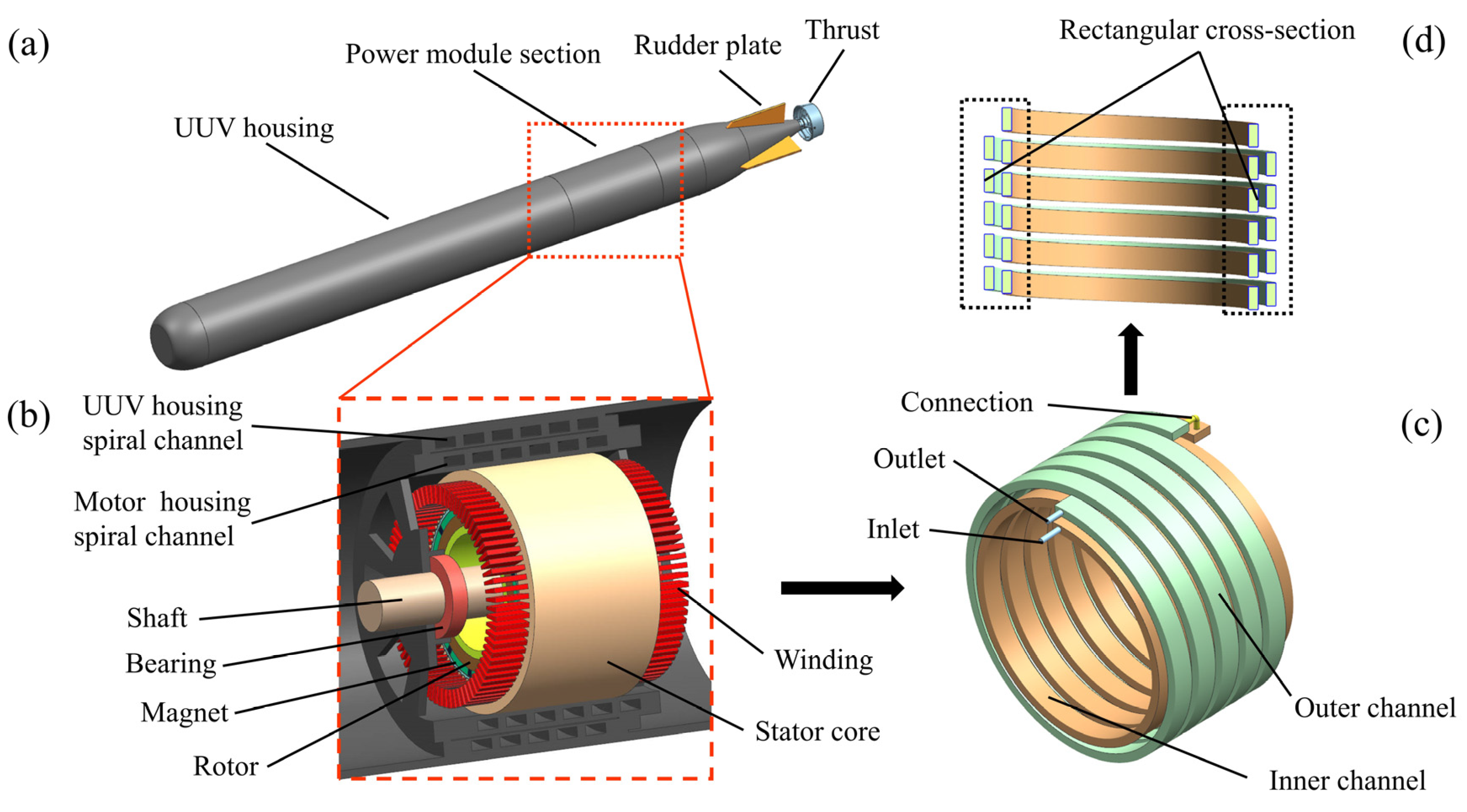
2.1. Motor Model and System Parameter

The UUV propulsion motor studied in this paper is a custom-designed permanent magnet synchronous motor (PMSM) with a rated power of 90 kW and a rated speed of 3000 rpm, and the specific structural parameters of the motor are presented in Table 1 [11,15]. The thermophysical parameters of the motor components are essential for motor analysis and cooling system design. Accurate knowledge of the physical parameters such as thermal conductivity and the specific heat of materials provides a data foundation for subsequent analytical strategies. The relevant parameters of the motor discussed in this paper are presented in Table 2 [11,15]. The losses of PMSM during normal operation, resulting from an inability to achieve 100% energy conversion between electrical and mechanical energy, primarily lead to a rise in motor temperature, affecting both efficiency and operational safety. By simulating the electromagnetic field of the motor under rated operating conditions [11], the loss values for each heating component under load conditions could be obtained, as shown in Table 3. Among these, winding losses represented the largest proportion, at 2.78 kW, followed by stator and rotor core losses of approximately 0.97 kW, while permanent magnet eddy current losses constituted the smallest share. Mechanical losses are typically challenging to obtain directly through electromagnetic field simulation or experimental measurements, and were estimated to be 2% of the total power. Using the loss values and the effective volume of the heat-generating components, the corresponding heat generation rate could be calculated, which provided data support for the simulation of the motor temperature field coupled with the flow field.
Considering the space limitation of the UUV energy compartment section and the drawbacks of conventional liquid-cooling structures, which are prone to leaks and unstable cooling performance, this study adopted a spiral water channel connected between the PMSM housing and the UUV housing as the cooling device. The inner and outer water channel were linked by pipelines, with the structural schematic diagram illustrated in Figure 2. To simplify the problem while maximizing the constraints of fluid–liquid heat transfer efficiency, the machining feasibility of the overall device, and the structural assembly rationality, the water channel was designed with a rectangular cross-section. Its overall cross-section is shown in Figure 3a. In this diagram, Wa and Wb represented the width and height of the outer channel inside the UUV housing, respectively. Na and Nb denote the width and height of the inner channel inside the motor housing, respectively, and d indicates the depth of the channel within the cooling structure inside the motor housing. One of the most frequently used parameters in the study of motor cooling systems is the maximum temperature of the motor. The maximum temperature is the maximum value measured in the temperature distribution of the internal components of the motor during operation, which is usually found in the parts of the motor where the internal heat load is most concentrated, especially in the winding region of the motor. The maximum temperature of a motor is a critical parameter in thermal management and performance evaluation, which directly affects the efficiency, long-term operational reliability, and service life of the motor. In the optimized design of the water-cooling system, it is essential to analyze not only the temperature field distribution and temperature rise data but also to comprehensively consider the fluid flow rate and flow losses, with the aim of reducing the cost of the research and component selection [44,45,46]. A flow rate that is too low will hinder effective heat transfer, leading to reduced cooling efficiency, while an excessively high flow rate may significantly increase flow losses. The key to integrating the flow losses of the water-cooling structure into the design evaluation is to monitor the pressure difference between the inlet and outlet of the cooling water within the system. This value quantifies the flow resistance and facilitates the assessment of the cooling efficiency relative to the overall performance of the system. Based on the above analysis, the design variables for the subsequent multi-objective optimization included Na, Nb, Wa, Wb, d, and the cooling water flow rate Qw. The response variables were the maximum temperature of the motor, Tmax, and the flow loss in the water-cooling structure, Pw. To ensure the structural strength and appropriate flow parameters of the motor, the initial design variables were set as Na = 24 mm, Nb = 10 mm, Wa = 24 mm, Wb = 10 mm, d = 5 mm, and Qw = 11 L/min. The range of values for each design variable is shown in Figure 3b, where the width of the inner and outer channel is 16~32 mm, the height is 8~12 mm, the depth of the inner channel groove is 4~6 mm, and the cooling water flow rate is 8~14 L/min.

2.2. Mathematical Model

2.2.1. Control Equations

The coolant in the cooling system should satisfy the three conservation laws regarding the conservation of mass, the conservation of momentum, and the conservation of energy [1,47]. In the steady-state process, these can be expressed mathematically as
( ρ u ) x + ( ρ v ) y + ( ρ w ) z = 0
ρ u u x + v u y + w u z = P x + μ α ( 2 u x 2 + 2 u y 2 + 2 u z 2 ) ρ u v x + v v y + w v z = P y + μ α ( 2 v x 2 + 2 v y 2 + 2 v z 2 ) ρ u w x + v w y + w w z = P z + μ α ( 2 w x 2 + 2 w y 2 + 2 w z 2 )
ρ c p u T x + v T y + w T z = K e ( 2 T x 2 + 2 T y 2 + 2 T z 2 )
where u, v, and w are the velocity of the fluid in the x, y, and z directions, respectively, and ρ is the density of the fluid. P is the pressure exerted on the fluid, μα is the effective viscosity of the fluid, cp denotes the constant pressure-specific heat capacity of the fluid, T is the temperature of the fluid, and Ke is the thermal conductivity of the fluid.
Since the coolant in the channel is usually in a turbulent state, the SST k-ω model can effectively capture the flow characteristics of the fluid in complex geometries and optimize the convective heat transfer efficiency [15]. At the same time, this model is able to balance the assessment of heat and pressure drop loss to ensure that the overall performance of the heat dissipation system is improved. The transport equation for the turbulent kinetic energy k of the fluid in this paper can be expressed as
ρ k t + ( ρ u k ) x = P k β ρ k ω + x [ ( μ + σ k μ t ) k x ]
where t is the flow time, Pk is the turbulence generation term, ω is the specific dissipation rate, and β is an empirical constant. μ is the molecular viscosity, μt is the turbulent viscosity, and σk is the Prandtl number of turbulent kinetic energy, which is usually taken as 1.
The transportation equation for the specific dissipation rate ω is
( ρ ω ) t + ρ u ω x = α ω k P k β 1 β ω 2 + x μ + σ ω μ t ω x + 2 ( 1 F 1 ) ρ σ ω ω k x ω x
where α and β1 are model constants and σω is the Prandtl number of the turbulence specific dissipation rate, which is usually taken to be 0.5. F1 is the mixing function that determines the weighting of the model in the near-wall region and in the free region.
The turbulent viscosity μt can be calculated using the following equation
μ t = ρ a 1 k m a x ( ω a 1 ,   S F 2 )
where a1 is the model constant, usually taken as 0.31. S is the strain rate and F2 is the mixing function used to determine how the model behaves in different regions.
The effect of radiant heat transfer on the motor temperature is slight compared to heat conduction and convection heat transfer [48]. Therefore, in this study, the heat transfer inside the motor is mainly through heat conduction, while convection and the effect of radiant heat transfer was neglected. The heat conduction is calculated as
Q = λ A T n
where Q is the thermal conductivity flow per unit time. A is the thermal conductivity area, λ is the thermal conductivity coefficient, and T n is the temperature gradient.
The heat transfer between the motor housing or UUV housing and the fluid in the cooling channel is controlled by convective heat transfer in accordance with Newton’s laws of cooling
Q q = h ( T α T w )
where Qq is the amount of heat transfer per unit area, and h is the convective heat transfer coefficient which determines the heat transfer capacity between the fluid and the wall. Tα is the temperature of the surface of the shell, and Tw indicates the temperature of the cooling water.
For the heat transfer model in the solid region of the motor system, the energy conservation equation can be expressed as follows
k s 2 T s x 2 + 2 T s y 2 + 2 T s z 2 + q = 0
where ks is the thermal conductivity of the solid material, Ts is the temperature of the solid region, and q is the calorific value per unit volume of the solid part.

2.2.2. Multi-Objective Optimization

Sensitivity analysis is used to investigate the degree of change and trend of the response variable by changing the values of the design variables within a certain range, in order to determine the degree of influence of each design variable on the response variable. After determining the range of values of the design variables, the sensitivity analysis of each variable is carried out based on the results of the CFD simulation
S A i = f m a x x i f m i n x i j n [ f m a x x j f m i n x j ]
where SAi denotes the sensitivity of a certain design variable to the response variable. fmax(xi) and fmin(xi) denote the maximum and minimum value of the response variable for all ranges of values, respectively, and n is the total number of samples.
A response surface model (RSM) is a regression model widely used for solving motor-related multi-objective optimization problems [35]. The specific mathematical description of the second-order polynomial response surface agent model is shown in Equation (11), which mainly obtains the approximate optimal solution of the optimization objective by determining the proportional relationship between multidimensional design variables and weight coefficients
y = β + i = 1 k β i x i + i = 1 k β i i x i 2 + < j β i j x i x j + ξ
where y is the response variable and xi is the design variable. β is the constant term of the model, which represents the response value when all independent variables are zero. βi is the linear coefficient, βii is the quadratic coefficient, and βij is the interaction term coefficient. ξ denotes the error term of the model. Based on the problem of the optimized motor cooling system in this paper, in order to better explore the effects caused by changes in the design variables on the response variables, a special form of RSM, namely, curve fitting, was used with the following expression
y = β 0 + β 1 x j + + β n x j n + ξ = i = 1 n β i x j i + ξ
The accuracy of the agent model can be verified by analyzing the fitting effect of the RSM. At present, the evaluation indexes commonly used for error analysis mainly include the coefficient of determination R2, the maximum absolute error MAE, and the root mean square error RMSE, which can be expressed in the form of Equations (13)–(15), respectively.
R 2 = i = 1 n t e s t ( y ^ i y ¯ i ) 2 i = 1 n t e s t ( y i y ¯ i ) 2 = 1 i = 1 n t e s t ( y i y ^ i ) 2 i = 1 n t e s t ( y i y ¯ i ) 2
M A E = M a x y i y ^ i
R M S E = 1 n i = 1 n t e s t ( y i y ^ i ) 2
where yi denotes the actual simulation value of the test sample point. y ^ i denotes the predicted value of the agent model and y ¯ i denotes the actual simulation mean value. ntest is the number of test samples.
Moreover, the multi-objective optimization problem can be described using exact mathematical expression [49]
m i n f x = [ f 1 x , f 2 x , , f m x ] T s . t . g i x 0   ( i = 1 , 2 , , p ) h j x = 0   ( j = 1 , 2 , , u ) x = ( x 1 , x 2 , , x n )
where f(x) is the set of objective functions to be solved. m is the number of objective functions. gi(x) and hj(x) denote the inequality constraint functions and the linear equality constraint functions, respectively. p and u indicate the number of two different types of constraint functions. x is the decision variable.

3. CFD Coupling Simulation

3.1. Numerical Conditions and Grid

In the water-cooling process of the motor, convective heat transfer is the primary mechanism for transferring heat from the motor to the cooling water, based on the principle outlined in Equation (8). The SST kω model effectively captures the details of the turbulent boundary layer near the wall, particularly in the cooling channel, and correctly simulates rapid changes in local flow characteristics to ensure calculation accuracy, thereby effectively assessing the heat transfer capacity of the cooling system. Water, as the cooling medium, was treated as an incompressible flow. In this paper, mass-flow-inlet was employed as the inlet boundary condition for the cooling water channel, with the flow rate set according to the cooling demands of the actual system and the characteristics of the fluid pump. To facilitate effective heat dissipation, real-time temperature transfer between the inlet and outlet wall surfaces of the water-cooling structure was achieved using the built-in user-defined function (UDF) in FLUENT software, enabling inlet and outlet temperature coupling through wall number identification. Both the cooling water channel and the solid inner wall were designated as no-slip walls, meaning the fluid velocity at the wall was zero, which was in line with the actual physical phenomenon. In this paper, FLUENT software 2022 R2 version was used for numerical simulation, and the solver employed a coupled algorithm for pressure–velocity coupling to ensure convergence and the stability of the calculations. A second-order upwind scheme was chosen for the discretization method to enhance computational accuracy, while the convergence criterion was set to residuals less than 10−6. Considering the complex geometry, the unstructured grid was utilized for meshing to ensure the accuracy of the flow field and heat transfer processes. To capture subtle flow characteristics near the wall, a boundary layer mesh was implemented at the water channel surface, maintaining y+ values between 1 and 5. Additionally, the smooth transition of the mesh was preserved throughout the meshing process to minimize numerical errors and enhance the stability of the calculations. Figure 4 illustrates the meshing of the cooling channel and the motor model presented in this paper [11].

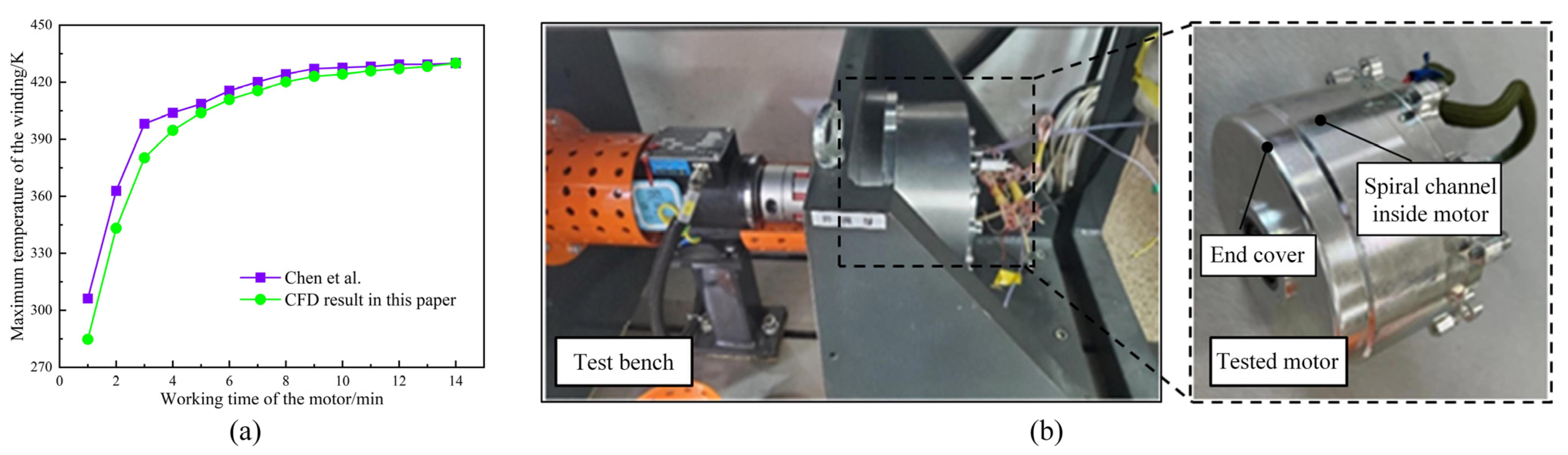
3.2. Numerical Validation

To ensure the accuracy of the simulation results, the grid independence validation of the cooling process in the dual cooling channel of the motor was conducted. Initially, a coarser mesh was used, and the density of the grid was gradually increased. Ultimately, six different grid quantities were selected for comparative analysis, with the results presented in Table 4 (the number in parentheses indicate the difference between the current results and those of the previous working condition). Tr, Tm, Ts, and Tw denote the maximum temperature of the motor rotor, magnet, stator, and winding, respectively. It can be observed that, as the number of grids increase, the results gradually stabilize. When the grid count reached 5.5 × 10⁶, the maximum temperature error of each heat-generating component of the motor was less than 0.2 K compared to the data obtained with 5 × 10⁶ grids, and the error in flow loss for the water-cooling structure was below 0.01 kPa. This indicates that further increases in grid density had a negligible effect on the numerical simulation results. To balance calculation accuracy and computational cost, 5.5 × 10⁶ grids were selected for subsequent calculations.
To verify the reliability of the numerical model used, the simulation of the motor cooling channel was compared with the data from Chen [11] et al. The results are presented in Figure 5a, where the variable of interest is the maximum temperature of the motor winding. Initially, a certain discrepancy was observed between the simulation results and the experimental data. However, as the cooling process stabilized, the results of both approaches converged, with the final error not exceeding 1%. Overall, the established numerical model demonstrates good accuracy and can be utilized in subsequent research and optimization efforts.

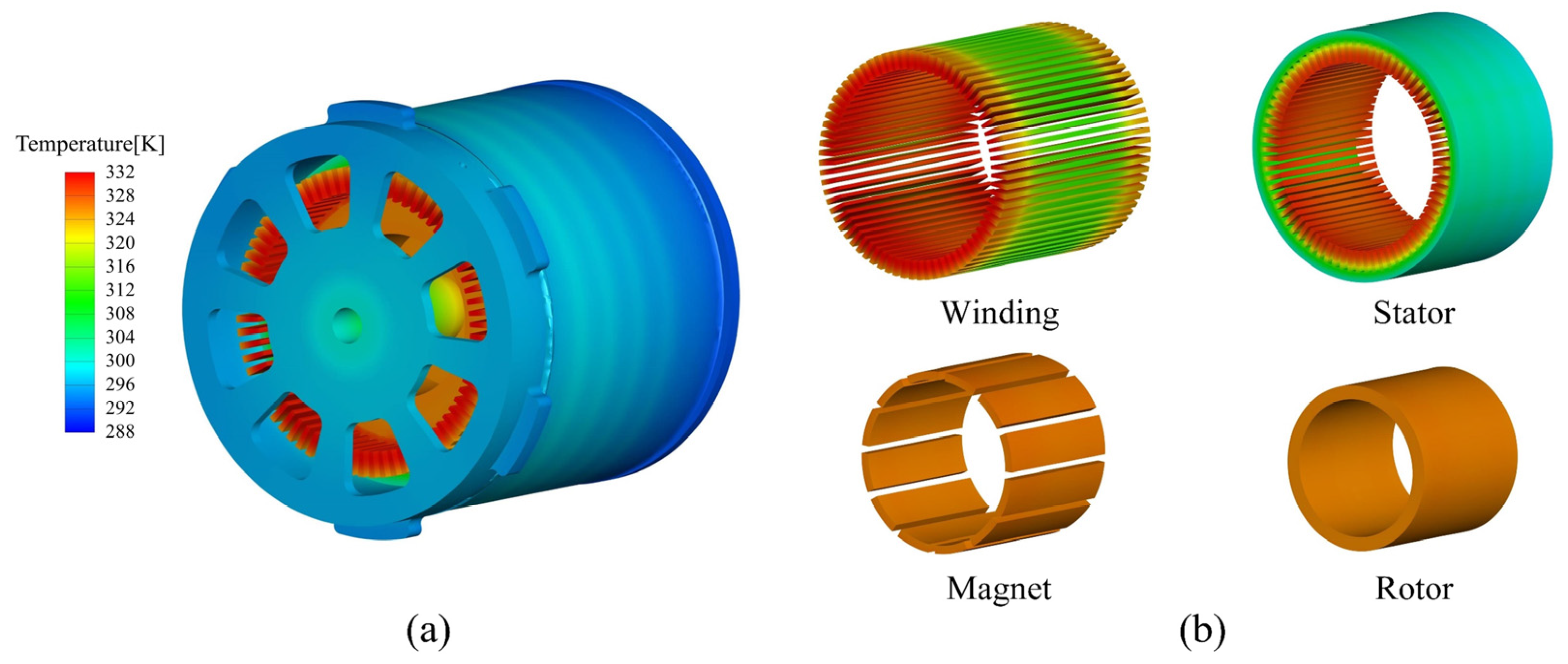
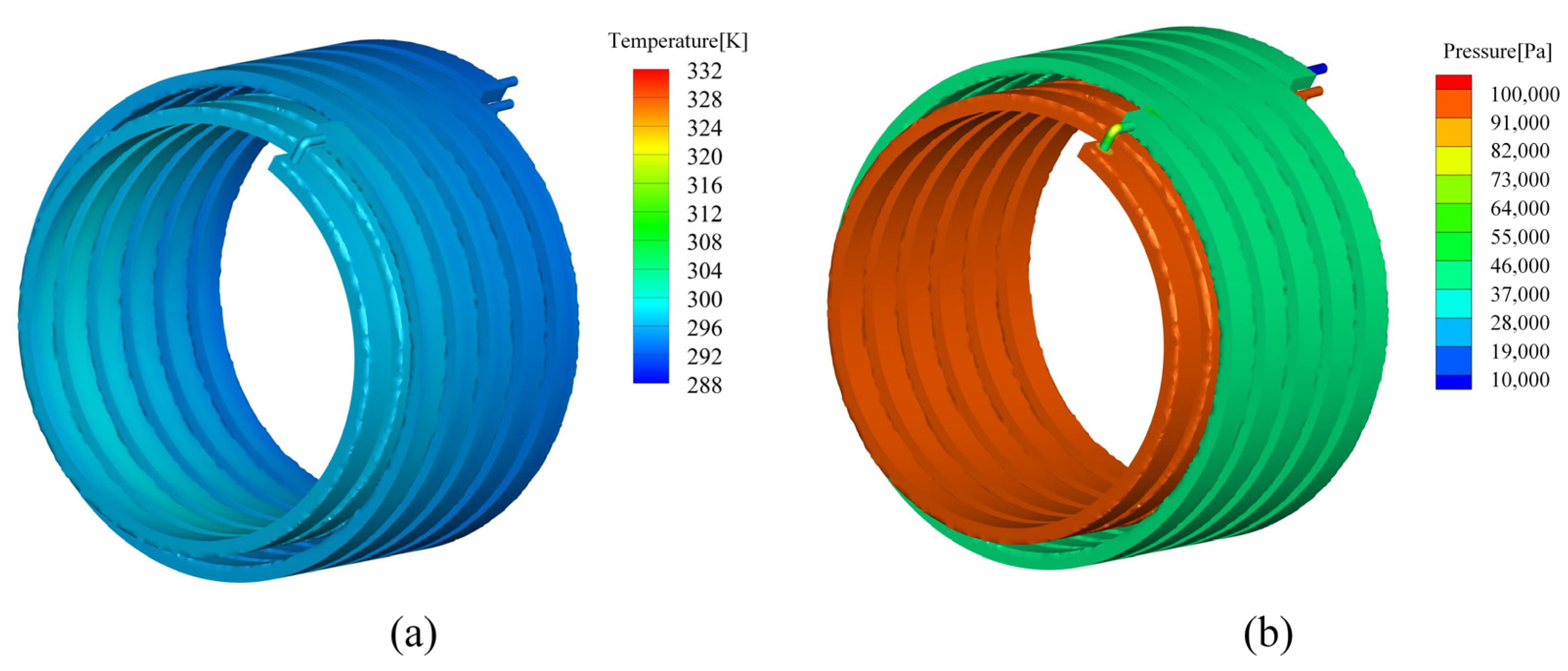
3.3. Numerical Results

The maximum temperature field distribution of the dual-channel motor system is presented in Figure 6, where the study variables are taken as Na = 24 mm, Nb = 10 mm, Wa = 24 mm, Wb = 10 mm, d = 5 mm, and Qw = 11 L/min. The maximum temperature in the motor occurred at the winding, reaching 322.86 K. It was attributed to significant resistance heat generation and heat accumulation during operation, making winding the primary area where heat was concentrated within the motor. Meanwhile, it was observed that the temperature at the ends of the winding was lower compared to that in the middle, and the temperature on the outer side of the winding ends was also lower than that on the inner side. This phenomenon occurred because the stator, as the external structure of the winding, effectively conducted heat and facilitated heat exchange with the cooling channel, enhancing the heat dissipation capability of the middle part of the winding. Furthermore, the inner water channel of the motor was spatially closer to the outer side of the winding, allowing for more efficient heat conduction to the outer side than to the inner side, resulting in a slightly lower temperature on the outer side compared to the inner side. Additionally, the high temperature of the stator core was primarily localized in the teeth that were in contact with the winding, where a more pronounced temperature buildup was observed. However, the overall temperature difference within the stator was clearly reduced. Figure 7 illustrates the temperature field and pressure distribution of the cooling water in the water channel. In Figure 7a, it can be observed that the maximum temperature of the cooling water remained below 300 K, with the temperature in the inner channel generally higher than that in the outer channel. The reason for this was that the cooling water first flowed through the inner channel of the motor, where it exchanged heat generated by convective heat transfer from the wall of the motor. The cooling water then entered the outer channel of the UUV housing through the connection, where the heat was transferred to seawater via the housing, facilitating the cooling process. Figure 7b displays the distribution of the total pressure of the cooling water. The pressure in the inner channel was primarily concentrated around 100 kPa, while the pressure in the outer channel was significantly lower than that in the inner channel. Except for the outlet, the pressure distribution in the remaining locations of the outer cooling water was relatively uniform, averaging around 60 kPa. Additionally, the calculated pressure difference between the inlet and outlet was 100.02 kPa.

4. Sensitivity Analysis

Before conducting multi-objective optimization, sensitivity analysis can elucidate the degree of correlation between each design variable and the response variable, as well as the change trends of these variables. This foundational understanding enables a more refined optimization process focused on the key variable. Five design variables were considered, the width of the inner cooling water channel Na, the height of the inner water channel Nb, the width of the outer water channel Wa, the height of the outer water channel Wb, the depth of the grooving in the inner water channel d, and the cooling water flow rate Qw. The data were calculated through coupled simulations of the temperature field and flow field. The influence of the dimensional parameters of the water-cooling structure and the cooling water flow rate on both the flow loss of the water-cooling structure and the maximum temperature of the motor was analyzed using Equation (10), with the results presented in Figure 8. This figure shows the magnitude of the effect of all design variables on the response variable, with values closer to 1 indicating a stronger influence. It suggests that a slight change in the design variable will lead to a more significant change in the response variable. Among them, Qw had the greatest influence on both the maximum temperature Tmax and the flow loss of the water-cooling structure Pw, exhibiting sensitivities of 77.79% and 99.84%, respectively. This indicated that Qw was the design parameter that should be prioritized and optimized in the motor cooling system design for this study. Meanwhile, Nb and d had the least influence on the sensitivity of Pw and Tmax, with values of 0.51% and 0.25%, respectively. Except for Qw, which significantly affected the flow loss of the water-cooling structure, all other design variables had a lesser impact. Specifically, Na, Wa, and Nb exhibited sensitivities of 10.60%, 9.05%, and 8.59%, respectively, for Pw. The depth of grooving d had an even smaller effect on Pw, with a sensitivity of only 1.01%, making it greater only than that of Nb. For the maximum temperature of the motor, in addition to d, which had the least effect on it, the other four geometry variables had different degrees of influence on Tmax. The sensitivity values for Wb and Nb were close, at 26.07% and 23.59%, respectively, indicating that their effects were weaker than those of both Qw and Na. Furthermore, Wa had the smallest sensitivity value, at 4.8%. Overall, except for the cooling water flow rate, the parameters of the inner channel generally exerted a greater influence on the response variables than those of the outer channel. This was primarily because the inner channel facilitated the transfer of heat generated by the motor to the outer channel, where it was then dissipated to seawater through convection. Consequently, the maximum temperature of the motor was more sensitive to the structural dimensions of the inner channel. Additionally, the cooling water flow rate in the inner channel was typically higher than in the outer channel, and minor changes in size can lead to larger hydraulic losses, resulting in increased or decreased flow loss in the water-cooling structure.
By analyzing the statistical relationship between the cooling water flow in the channel and the response variable, a corresponding fitting curve could be constructed, as illustrated in Figure 9. It is evident that Pw and Qw exhibit a high correlation, with the sample data points demonstrating a concentrated and more uniform distribution. In contrast, Tmax and Qw show a relatively lower correlation; however, the experimental sample points still display a consistent strip-like distribution, which could be attributed to the trade-offs and interactions between different objectives in the multi-objective optimization process, resulting in the dispersion of the temperature distribution. Therefore, future research could focus on optimizing these localized regions and exploring ways to enhance the uniformity and correlation of the temperature distribution through more refined design adjustments.

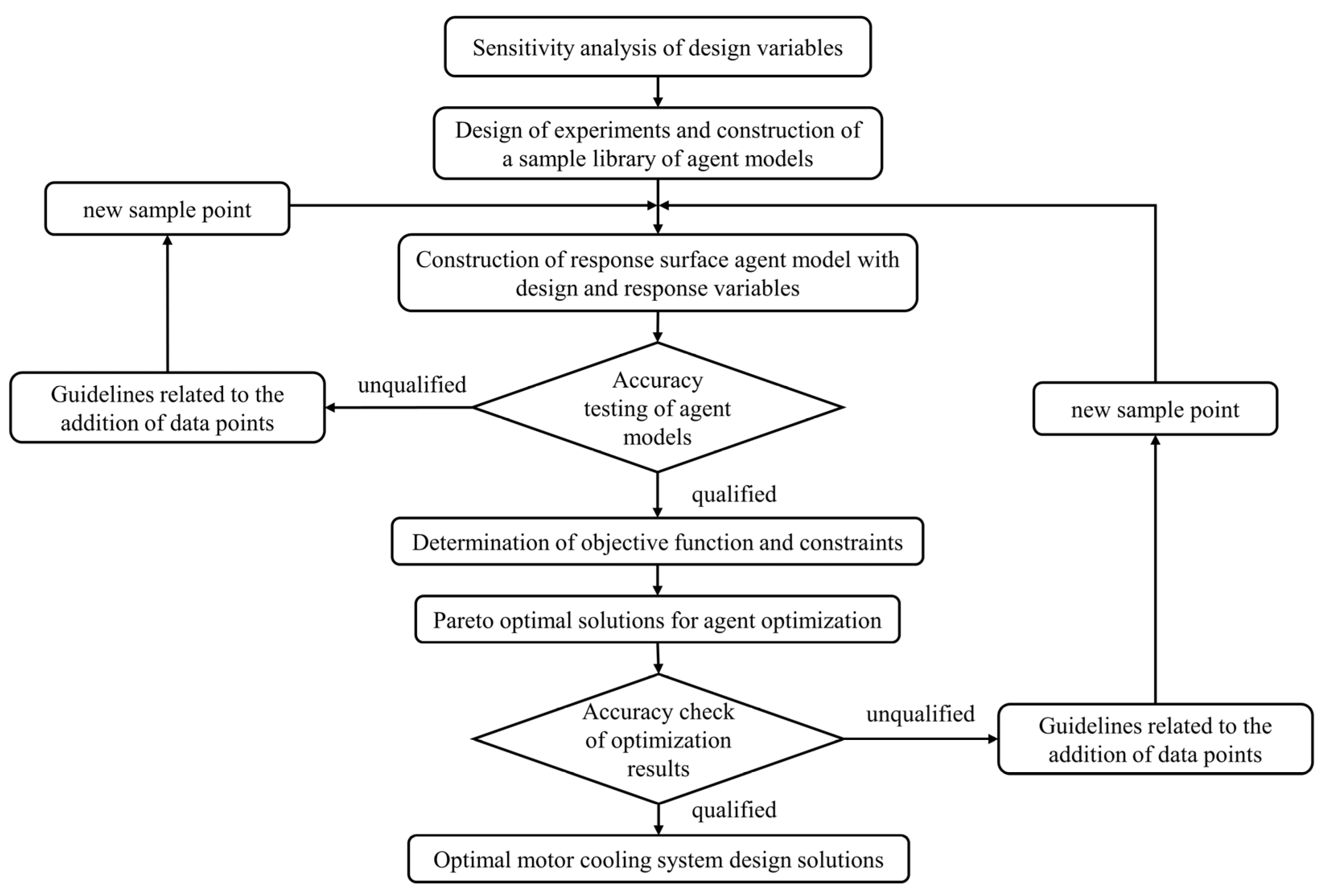
5. Construction and Validation of the Agent Model

5.1. Construction of RSM

There were six design variables to be optimized in this paper, the upper and lower value limits of which [Na, Nb, Wa, Wb, d, Qw] were [4,8,16] and [6,12,14,32], respectively. This ensured that each design variable could be sampled more evenly within its respective range of values to avoid the phenomenon of local aggregation of design variable values. On the other hand, this approach aimed to prevent dimensionality issues that could complicate the sample base construction for the agent model. Therefore, this study primarily employed the Latin hypercube sampling method [50,51]. Based on the number of design variables and the fundamental requirements for constructing the sample library of the agent model, the number of sample points should be at least ten times greater than the number of design variables. To ensure a sufficient number of sample points and maximize the predictive accuracy of the agent model, a total of 120 sample points were generated for CFD simulation coupling the temperature field and flow field in the design of the experiments. The distribution of the sample points for each design variable is shown in Figure 10. This paper focuses on the objective optimization of the motor cooling system. Due to the limited spatial dimensions and the few design variables involved, the response surface agent model was an ideal choice for achieving the optimization objectives, thanks to its high transparency and strong adaptability. Based on the type of optimization objective and the number of design variables, an appropriate type of response surface was selected, and the RSM was developed using the sample library obtained through the design of experiments.

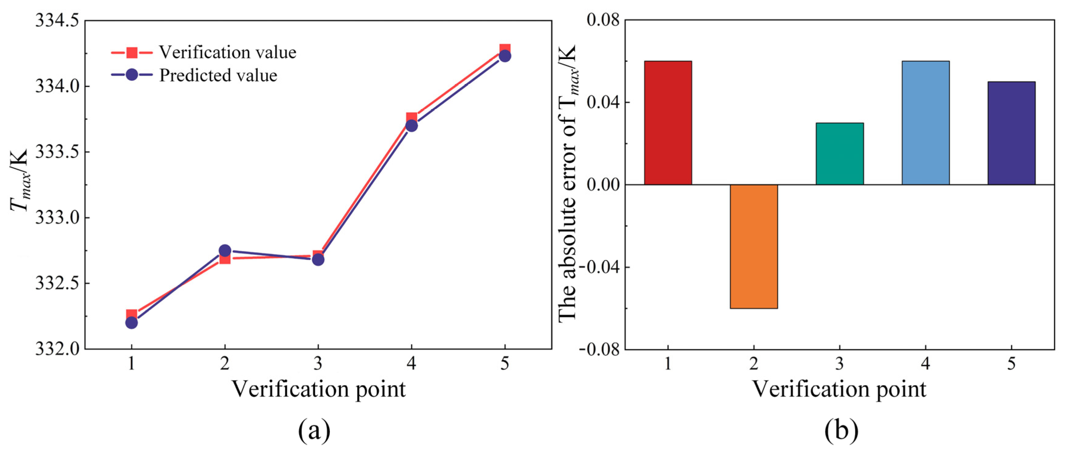
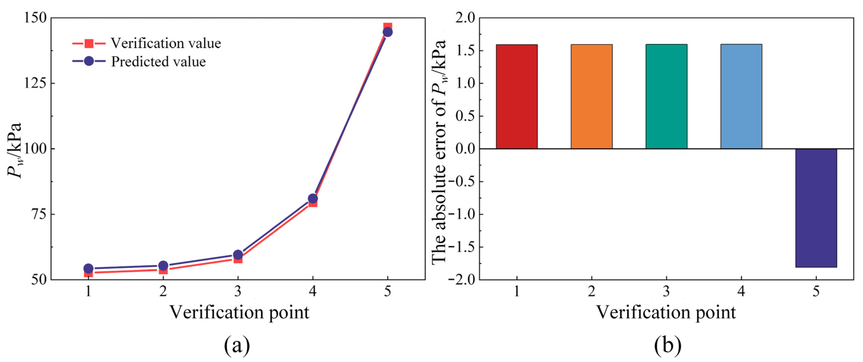
5.2. Validation of RSM

After creating the RSM based on the sample points from the agent model sample library, it was essential to evaluate the fitting accuracy of the model in relation to the sample data points. The fitting performance of the RSM was analyzed using Equations (13)–(15), and the error data are presented in Table 5. The coefficients of determination R2 for the RSM regarding Tmax and Pw are both above 0.99, nearly converging to 1. Additionally, the values of maximum absolute error MAE and root mean square error RMSE are all in the reasonable range. This indicates that the RSM created based on the agent model sample library exhibits an excellent fitting performance and high accuracy. Figure 11 illustrates the fitting effect of the RSM for the response variables Tmax and Pw, further demonstrating that the predicted values closely align with the sample library data points.
In addition to the aforementioned methods for evaluating the accuracy of the RSM, the prediction accuracy could be further assessed by generating validation points. The predictive capability of the agent model was verified by comparing the errors between the CFD simulation results of these validation points and the theoretical values provided by the agent model. A total of five sets of validation points were established to monitor the maximum temperature of the motor and the flow loss of the water-cooling structure in real time. Ultimately, the actual response values were compared with the predicted values to analyze and evaluate the magnitude of the errors. Figure 12 and Figure 13 present the results from the numerical simulations alongside the predicted values from the RSM for Tmax and Pw, respectively. The results indicate a close alignment between the two sets of values. The average absolute error of Tmax is only 0.052 K, while the average error of Pw is 1.636 kPa, both falling within approximately 1%. Consequently, the validation values from the simulations are consistent with the predicted values from the agent model. In summary, the fitting results of the RSM against the sample pool data and the comparison of the five validation points demonstrate that the model developed in this study exhibits high predictive accuracy and fitting quality. It could be used for subsequent analyses.

6. Optimization Results Analysis

Consistent with the creation of the RSM, the response variables in this section are the maximum temperature of motor Tmax and the flow loss of the water-cooling structure Pw. The design variables included Na, Wa, Nb, Wb, d, and Qw. The goal was to optimize the dimensional parameters of the dual-channel structure and the cooling water flow rate to minimize both the maximum temperature of the motor and the flow loss of the water-cooling structure. After establishing the optimization objectives and constraints, the mathematical model for the multi-objective optimization problem of the heat dissipation system can be formulated as follows:
m i n i m i z e { T m a x , P w } f i n d { N a , N b , W a , W b , d , Q w } s . t . 16   m m N a 32   m m 8   m m N b 12   m m 16   m m W a 32   m m 8   m m W b 12   m m 4   m m d 6   m m 8   L / m i n Q w 14   L / m i n
Based on the validation of the RSM completed in Section 5.2, a coupled multi-objective genetic algorithm was employed to minimize both the maximum temperature of the motor and the flow loss of the water-cooling structure. The optimal solution was selected according to actual requirements after obtaining the Pareto solution set, thereby completing the design of the motor heat dissipation system. According to the above objective function and constraints, the objective value of the optimization solution and the value range of each design variable were set in the program, and the initial parameters of the multi-objective genetic algorithm are shown in Table 6. Based on the agent model, Tmax and Pw were taken as the priority constraints, the objective function was defined to optimize the two objectives at the same time, and the optimal solution was finally determined by solving the Pareto solution set. In order to monitor in real time the trend of taking values in the optimization process of the maximum temperature of the motor and the flow loss of the water-cooling structure, five candidate points for the best selection were set, and the global optimization search process of the sample points is shown in Figure 14. Furthermore, as shown in Figure 15, the multi-objective genetic algorithm performed a global search within the respective value ranges of the design variables to complete the iterative calculation process of optimizing the target solution.
The distribution of available sample points and the Pareto solution set for Tmax and Pw, under the specified constraints, were calculated through iterative loops of the multi-objective genetic algorithm, as illustrated in Figure 16. The red section of the sample points, located beneath the area of available sample point distribution, constituted the Pareto solution set for the multi-objective optimization of Tmax and Pw. The sample points in region A focused on minimizing Tmax, while the available sample points in region D prioritized reducing Pw. Neither region accounted for the trade-off relationship with the other variable, making the sample points in A and D suboptimal for this multi-objective optimization. In contrast, the sample points between regions B and C effectively balanced the interaction between Tmax and Pw. Consequently, this study identified five optimal candidates for the maximum temperature of the motor and the flow loss of the water-cooling structure, primarily located in the BC region. These points considered multiple optimization objectives without exhibiting excessive bias towards any single objective. The distribution of the five candidate points and the corresponding optimization results for the response variables are presented in Table 7. Analysis of the data reveals that the optimal results for Tmax and Pw, achieved after numerous iterations, were 331.46 K and 59.58 kPa, respectively. This point represented the best available sample for optimization, as determined with the multi-objective genetic algorithm in accordance with the distribution of the Pareto solution set. Compared to the CFD calculation based on the initial parameters, Tmax decreased from 332.86 K to 331.46 K, resulting in an overall temperature reduction rate of 0.42%. Although the maximum temperature of the motor decreased, the improvement rate was relatively low. On the other hand, Pw decreased significantly from 100.02 kPa to 59.58 kPa, achieving a maximum improvement rate of 40.43%. In general, although the optimization result showed a limited reduction in Tmax, it effectively ensured motor temperature suppression while significantly lowering Pw. Unlike single-objective optimization, this approach balanced the trade-off between Tmax and Pw, allowing both to achieve lower values, thereby satisfying the fundamental requirements of the multi-objective optimization problem.
The design variable parameter settings for candidate point 1, which exhibited the best optimization effect, were selected to establish the corresponding three-dimensional motor temperature field model. The accurate numerical calculation of the coupled temperature and flow fields were performed, with the resulting temperature field of the motor and the pressure distribution of the water-cooling structure shown in Figure 17. From the contour, it was evident that the highest temperature of the motor occurred at the end of the stator winding, reaching a maximum value of 331.51 K. The maximum absolute error compared to the target optimized value of 331.36 K from candidate point 1 was 0.05 K. The pressure distribution of the water-cooling structure indicated a high pressure in the inner water channel and a lower pressure in the outer water channel. In this case, the CFD calculation of the flow loss of the water-cooling structure yielded a value of 59.16 kPa, resulting in a maximum absolute error of 0.42 kPa compared to the target optimized value of 59.58 kPa. Notably, the errors for both Tmax and Pw were below 1%. These results demonstrate the significant predictive accuracy and precision of the multi-objective optimization method employed in this study for optimizing the dual-channel cooling system for the motor. The final results obtained for the optimum motor cooling system design for the best performance of both Tmax and Pw for each of the design and response variables [Wa, Wb, Na, Nb, d, Qw, Tmax, and Pw] were [20.33 mm, 11.92 mm, 17.78 mm, 9.10 mm, 5.13 mm, 9.62 L/min, 331.46 K, and 59.58 kPa].

7. Conclusions

This study focuses on the dual-channel cooling system of a UUV propulsion motor, using the maximum temperature of the motor and the flow loss of the water-cooling structure as optimization objectives. A multi-objective optimization design was performed to match the dimensional parameters of the cooling structure and the cooling water flow rate, utilizing the multi-objective genetic algorithm. This paper developed an RSM based on sensitivity analysis and validated its effectiveness. By combining it with a multi-objective genetic algorithm, suitable optimization candidate points were identified, and the validity of the optimization results was confirmed through comparison with CFD results. The objective was to optimize the heat dissipation system, enhancing its operational efficiency and reliability. The methodologies employed and the results obtained in this study contribute to the advancement of related technologies and hold significant practical application value. The main conclusions are as follows:
(1)
The sensitivity analysis results indicate that the cooling water flow rate Qw has the most significant impact on both Tmax and Pw, with sensitivities of 77.79% and 99.84%, respectively. In contrast, the sensitivity of the cross-sectional dimensions of the inner and outer channel on Tmax was approximately 20%, while their effects on Pw were relatively minor, generally below 10%.
(2)
For the multi-objective optimization of the motor cooling system design, the response surface agent model was constructed using Latin hypercube sampling. The prediction accuracy was validated through test samples, revealing an average error of less than 1% between the predicted and verification values, which proved the validity and reliability of this agent model in the optimization of motor cooling systems.
(3)
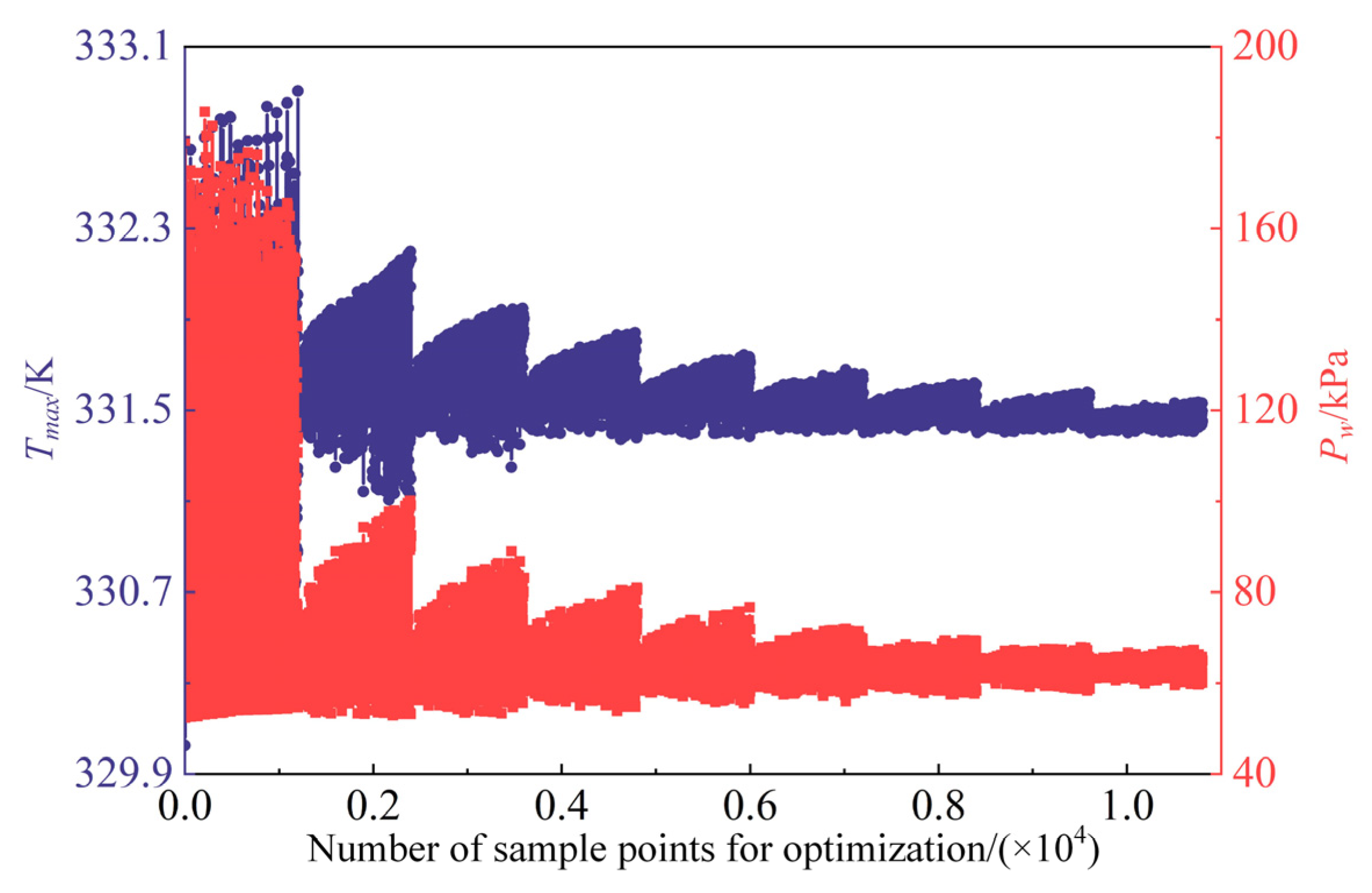
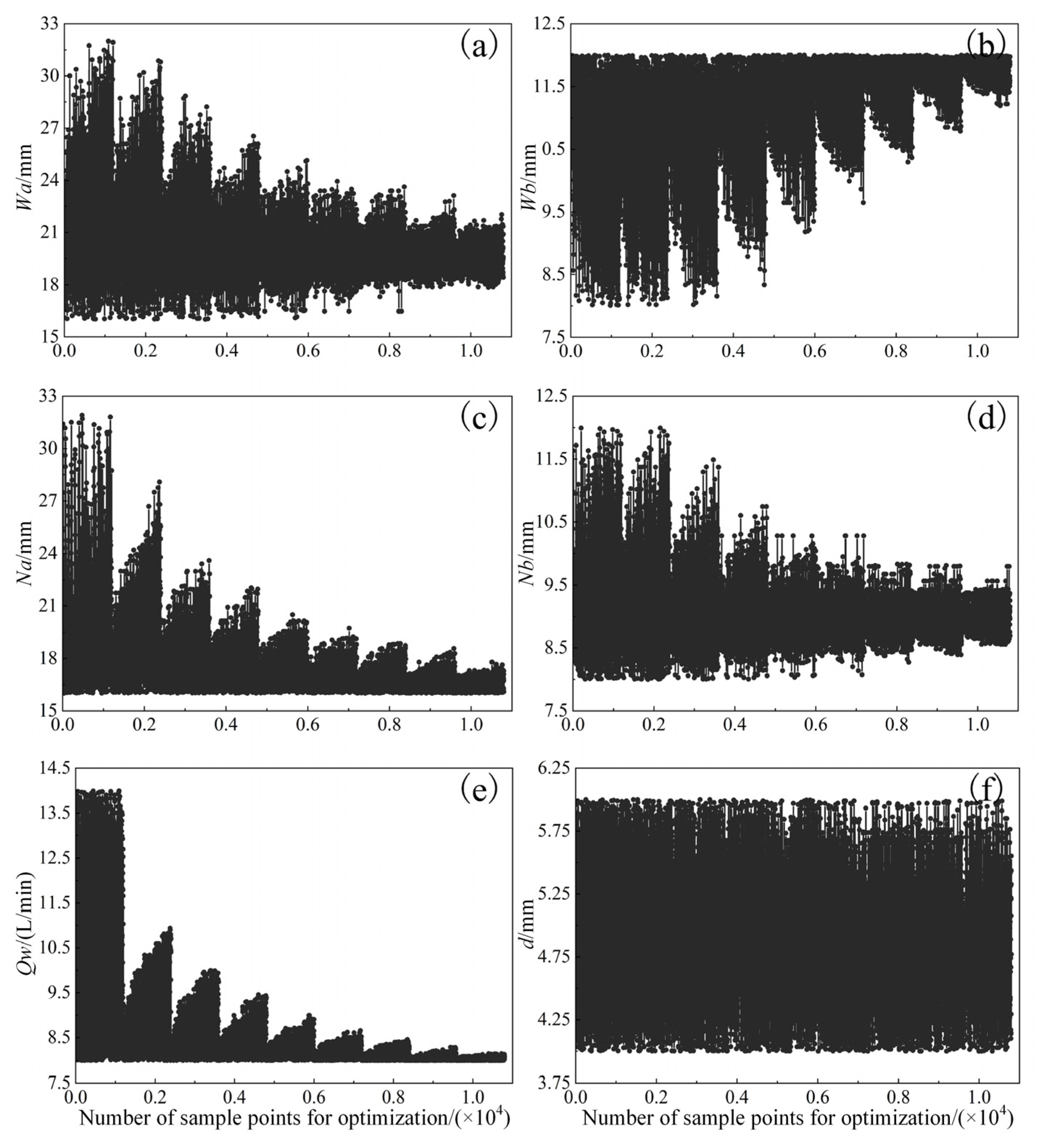
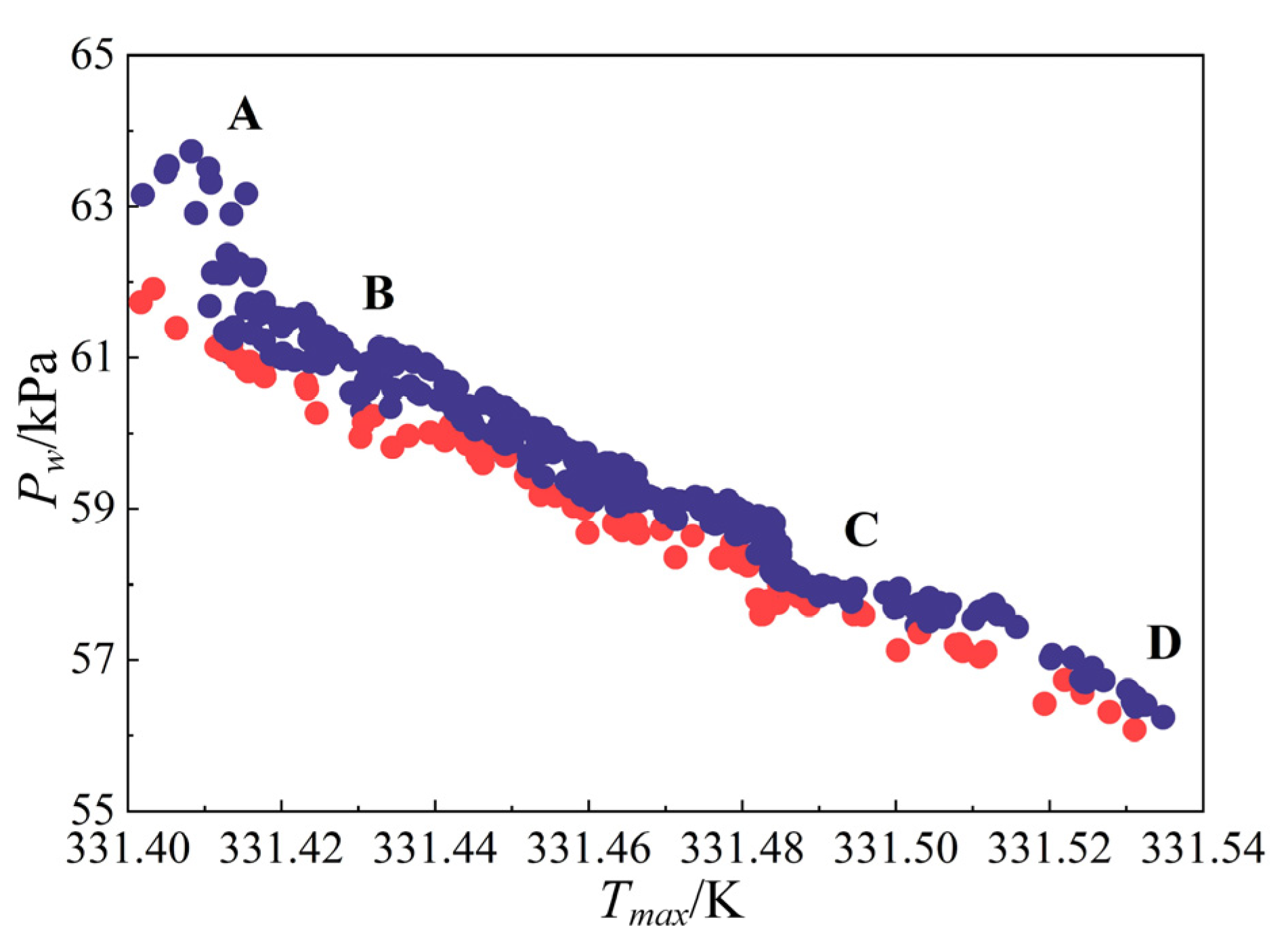
Sample points were selected from the Pareto solution set and their comparison with CFD simulations revealed that the maximum absolute errors of the response variables were all below 1%. The optimized design variables for the cooling structure were [Wa, Wb, Na, Nb, d, Qw] = [20.33 mm, 11.92 mm, 17.78 mm, 9.10 mm, 5.13 mm, 9.62 L/min]. Compared to the initial parameters, the maximum temperature of the motor decreased from 332.86 K to 331.46 K. The flow loss of the water-cooling structure decreased from 100.02 kPa to 59.58 kPa, achieving a maximum improvement rate of 40.43%, demonstrating a significant overall optimization effect.

Author Contributions

Conceptualization, all authors; methodology, W.T. and B.C.; software, W.T. and C.Z.; validation, B.C.; data analysis, C.Z.; manuscript writing, C.Z.; review and editing, Z.M., W.T. and B.C.; visualization, C.Z.; supervision, Z.M. All authors have read and agreed to the published version of the manuscript.

Funding

This work was supported by the Innovation Foundation for Doctor Dissertation of Northwestern Polytechnical University, the Fundamental Research Funds for the Central Universities, and the National Natural Science Foundation of China (No. 52471346).

Institutional Review Board Statement

Not applicable.

Informed Consent Statement

Not applicable.

Data Availability Statement

The data are available from the corresponding author on reasonable request.

Conflicts of Interest

The authors declare no conflict of interest.

Nomenclature

Wawidth of the water channel outside the UUV housing
Wbheight of the water channel outside the UUV housing
Nawidth of the water channel inside the motor housing
Nbheight of the water channel inside the motor housing
dgroove depth of the inner water channel in the motor housing
Qwvolume flow rate of cooling water
Tmaxmaximum temperature of the motor
Pwflow loss of water-cooled structure
xx-direction scale in 3D coordinate system
yy-direction scale in 3D coordinate system
zz-direction scale in 3D coordinate system
ttime scale
uvelocity of the fluid in the x-direction
vvelocity of the fluid in the y-direction
wvelocity of the fluid in the z-direction
ρdensity of the fluid
Ppressure on the fluid
μαeffective viscosity of the fluid
c p constant pressure specific heat capacity of the fluid
Ttemperature of the fluid
K e thermal conductivity of the fluid
kturbulent kinetic energy
ωspecific dissipation rate
P k turbulence generation term
βempirical constant of the turbulent kinetic energy transport equation
μ molecular viscosity
μ t turbulent viscosity
σ k Prandtl number of turbulent kinetic energy
α , β 1 , a 1 model constant
σ ω Prandtl number of turbulent specific dissipation rate
F 1 , F 2 blending function
Sstrain rate
Qthermal conductivity flow per unit time
Athermal conductivity area
λ thermal conductivity
T / N temperature gradient
Q q heat transfer per unit area
hconvective heat transfer coefficient
T α temperature of the shell surface
Twtemperature of the cooling water
ksthermal conductivity of the solid material
Tstemperature of the solid region
qcalorific value per unit volume of the solid
SAisensitivity of a design variable to a response variable
fmax(xi)maximum value of the response variable within the range of value
fmin(xi)minimum value of the response variable within the range of value
ntotal number of samples
y response variable
xidesign variable
β constant term for response surface model
β i linear coefficient for response surface model
β i i quadratic coefficient for response surface model
β i j interaction term coefficient for response surface model
ξerror term in response surface model
R2coefficient of determination
MAEmaximum absolute error
RMSEroot mean square error
yiactual simulation value for test sample point
y ^ i predicted value of the agent model
y ¯ i average of actual simulation
ntestnumber of test sample
f(x)the set of objective function to be solved
mnumber of objective function
gi(x)inequality bound function
hj(x)linear equation constraint function
pthe number of inequality constraint function
uthe number of linear equation constraint function
x decision variable
Trmaximum temperature of the motor rotor
Tmmaximum temperature of the motor magnet
Tsmaximum temperature of the motor stator
Twmaximum temperature of the motor winding

References

  1. Cheng, B.; Qin, D.; Hu, Z. Research on the propulsion motor cooling by the coupled flow field of unmanned underwater vehicles. Appl. Therm. Eng. 2024, 237, 121797. [Google Scholar] [CrossRef]
  2. Zhang, B.; Ji, D.; Liu, S.; Zhu, X.; Xu, W. Autonomous Underwater Vehicle navigation: A review. Ocean Eng. 2023, 273, 113861. [Google Scholar] [CrossRef]
  3. Mondal, K. Autonomous Underwater Vehicles: Recent Developments and Future Prospects. Int. J. Res. Appl. Sci. Eng. Technol. 2019, 7, 215–222. [Google Scholar] [CrossRef]
  4. Li, W.; Cao, Z.; Zhang, X. Thermal Analysis of the Solid Rotor Permanent Magnet Synchronous Motors With Air-Cooled Hybrid Ventilation Systems. IEEE Trans. Ind. Electron. 2022, 69, 1146–1156. [Google Scholar] [CrossRef]
  5. Repecho, V.; Bin Waqar, J.; Biel, D.; Dòria-Cerezo, A. Zero Speed Sensorless Scheme for Permanent Magnet Synchronous Machine Under Decoupled Sliding-Mode Control. IEEE Trans. Ind. Electron. 2022, 69, 1288–1297. [Google Scholar] [CrossRef]
  6. Kim, K.; Lee, M.; Lee, S.; Jang, G. Optimal design and experimental verification of fluid dynamic bearings with high load capacity applied to an integrated motor propulsor in unmanned underwater vehicles. Tribol. Int. 2017, 114, 221–233. [Google Scholar] [CrossRef]
  7. Lei, S.; Xin, S.; Liu, S. Separate and integrated thermal management solutions for electric vehicles: A review. J. Power Sources 2022, 550, 232133. [Google Scholar] [CrossRef]
  8. Wang, Q.; Wu, Y.; Niu, S.; Zhao, X. Advances in Thermal Management Technologies of Electrical Machines. Energies 2022, 15, 3249. [Google Scholar] [CrossRef]
  9. Wu, P.-S.; Hsieh, M.-F.; Cai, W.L.; Liu, J.-H.; Huang, Y.-T.; Caceres, J.F.; Chang, S.W. Heat transfer and thermal management of interior permanent magnet synchronous electric motor. Inventions 2019, 4, 69. [Google Scholar] [CrossRef]
  10. Yu, W.; Hua, W.; Zhang, Z. Cooling Analysis of High-Speed Stator-Permanent Magnet Flux-Switching Machines for Fuel-Cell Electric Vehicle Compressor. IEEE Trans. Veh. Technol. 2022, 71, 210–219. [Google Scholar] [CrossRef]
  11. Chen, W.; Mao, Z.; Tian, W. Water cooling structure design and temperature field analysis of permanent magnet synchronous motor for underwater unmanned vehicle. Appl. Therm. Eng. 2024, 240, 122243. [Google Scholar] [CrossRef]
  12. Park, J.; An, J.; Han, K.; Choi, H.-S.; Seouk Park, I. Enhancement of cooling performance in traction motor of electric vehicle using direct slot cooling method. Appl. Therm. Eng. 2022, 217, 119082. [Google Scholar] [CrossRef]
  13. Wan, Z.; Sun, Y.; Hu, L.; Yu, H. Dynamic softening behavior and microstructural characterization of TiAl-based alloy during hot deformation. Mater. Charact. 2017, 130, 25–32. [Google Scholar] [CrossRef]
  14. Zhang, Z.; Song, Q.; Wang, X.; Zhao, S.; Shah, S.W.A. Reynolds number based optimization on liquid cooling system for permanent magnet synchronous motor of electric vehicle. Case Stud. Therm. Eng. 2024, 60, 104720. [Google Scholar] [CrossRef]
  15. Ou, H.; Hu, Y.; Tian, W.; Mao, Z.; Cheng, B.; Li, B. Investigation of self-adjusting cooling system for the autonomous underwater vehicle propulsion motor. Appl. Therm. Eng. 2024, 238, 121972. [Google Scholar] [CrossRef]
  16. Chen, W.; Luo, Q.; Cai, Z.; Wang, C. Temperature field analysis and cooling structure optimization of permanent magnet linear synchronous motor. Therm. Sci. Eng. Prog. 2024, 50, 102532. [Google Scholar] [CrossRef]
  17. Lee, Y.; Choi, H.; Park, P.; Lee, H. Multi-objective optimization of a U-shaped water jacket with a guide vane for improving the thermal performance of 20kW in-wheel motor. Case Stud. Therm. Eng. 2024, 53, 103927. [Google Scholar] [CrossRef]
  18. Li, C.; Guan, Z.; Li, J.; Zhao, B.; Ding, X. Optimal design of cooling system for water cooling motor used for mini electric vehicle. In Proceedings of the 2017 20th International Conference on Electrical Machines and Systems (ICEMS), Sydney, NSW, Australia, 11–14 August 2017; pp. 1–4. [Google Scholar]
  19. Baojun, G.; Jiong, Z.; Tao, D. Temperature prediction and cooling structure optimization of explosion-proof high pressure water-cooled double speed motor. Energy Rep. 2022, 8, 3891–3901. [Google Scholar] [CrossRef]
  20. Jha, P.; Hussain, M.; Khan, M.K. Numerical evaluation of nanofluid-based indirect liquid cooling of a Li-ion battery pack using equivalent circuit model under static and dynamic loading conditions. Int. Commun. Heat Mass Transf. 2024, 159, 108079. [Google Scholar] [CrossRef]
  21. Kumar Srinivasan, N.; Ponnusamy, C. Stability, thermal and solidification behaviour of oxygen functionalized GNPs–CuO/water-based hybrid nanofluid phase change materials for cool thermal energy storage system. J. Energy Storage 2024, 98, 113107. [Google Scholar] [CrossRef]
  22. Kim, S.; Lee, S.; Kang, D.G.; Kim, M.S. Motor cooling method using flow boiling of two-phase refrigerant and its analysis with lumped parameter thermal model. Int. J. Therm. Sci. 2023, 192, 108458. [Google Scholar] [CrossRef]
  23. Li, M.; Ma, C.; Liu, J. Topology optimization design of cooling water jacket structure for highspeed spindle-bearing system. J. Manuf. Process. 2023, 102, 1–22. [Google Scholar] [CrossRef]
  24. Zaniewski, D.; Klimaszewski, P.; Klonowicz, P.; Witanowski, Ł.; Lampart, P.; Jędrzejewski, Ł.; Suchocki, T. Organic Rankine cycle turbogenerator cooling–Optimization of the generator water jacket heat exchange surface. Appl. Therm. Eng. 2023, 223, 120041. [Google Scholar] [CrossRef]
  25. Zhu, G.; Li, L.; Mei, Y.; Liu, T.; Xue, M. Design and Analysis of a Self-Circulated Oil Cooling System Enclosed in Hollow Shafts for Axial-Flux PMSMs. IEEE Trans. Veh. Technol. 2022, 71, 4879–4888. [Google Scholar] [CrossRef]
  26. Wang, H.; Qiu, B.; Zhao, F.; Yan, T.; Li, C. Research on enhancing power plant net power by integrating modeling heat transfer and operation optimization of once-through cooling water system. Case Stud. Therm. Eng. 2024, 61, 104966. [Google Scholar] [CrossRef]
  27. Ye, W.; Liu, Y.; Wu, G.; Wu, Q.; Chen, Z.; Chen, Z.; Li, Z.; Cao, Z. Design optimization and manufacture of permanent magnet synchronous motor for new energy vehicle. Energy Rep. 2022, 8, 631–641. [Google Scholar] [CrossRef]
  28. Xia, T.; Zhang, C.; Li, H. Optimizing coolant loop design across the stator core: A research study. Heliyon 2024, 10, e36865. [Google Scholar] [CrossRef]
  29. Liu, H.; Xie, J.; Ma, X. Multi-objective optimization analysis of air-cooled heat dissipation coupled with thermoelectric cooling of battery pack based on orthogonal design. Appl. Therm. Eng. 2024, 249, 123402. [Google Scholar] [CrossRef]
  30. Ahmed, S.; Grabher, C.; Kim, H.-J.; Koseki, T. Multifidelity Surrogate Assisted Rapid Design of Transverse-Flux Permanent Magnet Linear Synchronous Motor. IEEE Trans. Ind. Electron. 2020, 67, 7280–7289. [Google Scholar] [CrossRef]
  31. Rafiee, V.; Faiz, J. Robust Design of an Outer Rotor Permanent Magnet Motor Through Six-Sigma Methodology Using Response Surface Surrogate Model. IEEE Trans. Magn. 2019, 55, 1–10. [Google Scholar] [CrossRef]
  32. Xu, L.; Xu, Y.; Gong, J. Analysis and Optimization of Cogging Torque in Yokeless and Segmented Armature Axial-Flux Permanent-Magnet Machine with Soft Magnetic Composite Core. IEEE Trans. Magn. 2018, 54, 1–5. [Google Scholar] [CrossRef]
  33. Bittner, F.; Hahn, I. Kriging-Assisted Multi-Objective Particle Swarm Optimization of permanent magnet synchronous machine for hybrid and electric cars. In Proceedings of the 2013 International Electric Machines & Drives Conference, Chicago, IL, USA, 12–15 May 2013; pp. 15–22. [Google Scholar]
  34. Chen, S.; Arabkoohsar, A.; Yang, Y.; Zhu, T.; Nielsen, M.P. Multi-objective optimization of a combined cooling, heating, and power system with subcooled compressed air energy storage considering off-design characteristics. Appl. Therm. Eng. 2021, 187, 116562. [Google Scholar] [CrossRef]
  35. Mi, S.; Liu, J.; Cai, L.; Xu, C. Multi-objective optimization of two-phase ice slurry flow and heat transfer characteristics in helically coiled tubes with RSM and NSGA-II. Int. J. Therm. Sci. 2024, 199, 108942. [Google Scholar] [CrossRef]
  36. Zhang, Z.; He, H.; Quan, S.; Chen, J.; Han, R. Multi-parameter and multi-objective optimization of dual-fuel cell system heavy-duty vehicles: Sizing for serial development. Energy 2024, 308, 132857. [Google Scholar] [CrossRef]
  37. Pandya, S.B.; Jangir, P.; Mahdal, M.; Kalita, K.; Chohan, J.S.; Abualigah, L. Optimizing brushless direct current motor design: An application of the multi-objective generalized normal distribution optimization. Heliyon 2024, 10, e26369. [Google Scholar] [CrossRef]
  38. Li, Y.; Li, C.; Garg, A.; Gao, L.; Li, W. Heat dissipation analysis and multi-objective optimization of a permanent magnet synchronous motor using surrogate assisted method. Case Stud. Therm. Eng. 2021, 27, 101203. [Google Scholar] [CrossRef]
  39. Hendre, O.; Kale, P.; Gore, R.; Pardeshi, N. Numerical study of water cooling jacket of a diesel engine using coupled field analysis. Mater. Today Proc. 2023, 77, 739–747. [Google Scholar] [CrossRef]
  40. Song, X.G.; Kang, S.H.; Park, Y.C. Thermal Performance Prediction and Optimization of Heat Sink with Jet Impingement Based on Adaptive Surrogate Model. In AIP Conference Proceedings-American Institute of Physics; AIP: Las Vegas, NV, USA, 2012; pp. 420–427. [Google Scholar]
  41. Saleem, A.; Hyeon Park, M.; Ambreen, T.; Chul Kim, S. Optimization of oil flow distribution inside the in-wheel motor assembly of electric vehicles for improved thermal performance. Appl. Therm. Eng. 2022, 201, 117753. [Google Scholar] [CrossRef]
  42. Yu, Y.; Liang, C.; Zeng, D.; Hu, Y.; Yang, J. Multi-objective optimization of IPMSM for electric vehicles based on the combinatorial surrogate model and the hierarchical design method. Int. J. Electr. Power Energy Syst. 2024, 162, 110245. [Google Scholar] [CrossRef]
  43. Keshavarzzadeh, A.H.; Maleki Zanjani, A.; Gharali, K.; Dusseault, M.B. Multi-objective evolutionary-based optimization of a ground source heat exchanger geometry using various optimization techniques. Geothermics 2020, 86, 101861. [Google Scholar] [CrossRef]
  44. Sun, Y.; Zhang, S.; Chen, G.; Tang, Y.; Liang, F. Experimental and numerical investigation on a novel heat pipe based cooling strategy for permanent magnet synchronous motors. Appl. Therm. Eng. 2020, 170, 114970. [Google Scholar] [CrossRef]
  45. Zhang, D.; Li, H.; Tian, Y.; You, R.; Zhang, X.; Wu, A. Effects of a high Reynolds number and rotation on the leading-edge heat transfer of a ribbed cooling channel with a cross-section consisting of a semicircle and a rectangle. Int. J. Heat Mass Transf. 2022, 188, 122646. [Google Scholar] [CrossRef]
  46. Chang, B.; Yuan, T.; Wang, Y.; Guo, H.; Li, Z.; Zhao, L.; Zhang, C.; Peng, S.; Deng, J. Cooling performance enhancement of electric vehicle film capacitor for ultra-high temperatures using micro-channel cold plates thermal management system. Int. J. Heat Mass Transf. 2024, 233, 126037. [Google Scholar] [CrossRef]
  47. Wang, Z.; Guan, Q.; Zhang, H.; Wu, X.; Yu, D. Optimized design of liquid-cooled plate structure for flying car power battery system. J. Energy Storage 2024, 97, 112720. [Google Scholar] [CrossRef]
  48. Chang, M.; Lai, B.; Wang, H.; Bai, J.; Mao, Z. Comprehensive efficiency analysis of air-cooled vs water-cooled electric motor for unmanned aerial vehicle. Appl. Therm. Eng. 2023, 225, 120226. [Google Scholar] [CrossRef]
  49. Lin, X.; Lin, Z.; Wei, S. Multi-objective optimized driving strategy of dual-motor EVs using NSGA-II as a case study and comparison of various intelligent algorithms. Appl. Soft Comput. 2021, 111, 107684. [Google Scholar] [CrossRef]
  50. Lu, L.; Li, G.; Xing, P.; Gao, H.; Song, Y.; Zhang, H. Numerical calculation and experimental investigation of the dynamic alignment of ship propulsion shafting based on Latin hypercube stochastic finite element. Ocean Eng. 2024, 296, 116935. [Google Scholar] [CrossRef]
  51. Liu, H.; Niu, W.; Guo, Y. Direct torque control for PMSM based on the RBFNN surrogate model of electromagnetic torque and stator flux linkage. Control Eng. Pract. 2024, 148, 105943. [Google Scholar] [CrossRef]
Figure 1. Flow chart of multi-objective genetic algorithm optimization of the cooling system.
Jmse 12 02133 g001
Figure 2. Schematic diagram of the cooling structure of the UUV propulsion motor: (a) overall structure of the UUV; (b) the structure of the dual-water-channel system; (c) the structure of the inner and outer water channel; (d) rectangular cross-section of the dual water channel.
Jmse 12 02133 g002
Figure 3. Parameters involved in the water-cooling system: (a) cross-sectional and dimensional parameters of the dual-channel water-cooling structure; (b) range of values of the design variables for multi-objective optimization.
Jmse 12 02133 g003
Figure 4. Mesh division: (a) mesh of the internal cooling structure of the motor; (b) mesh of the entire motor.
Jmse 12 02133 g004
Figure 5. Validation of the numerical model: (a) validation result graph; (b) photograph of the tested motor.
Jmse 12 02133 g005
Figure 6. Temperature field distribution of the water-cooling motor system: (a) the contour of the motor system’s temperature field; (b) the contour of the temperature field for the heated parts of the motor system.
Jmse 12 02133 g006
Figure 7. Results of the cooling water in the dual channel: (a) the contour of the temperature field for the cooling water; (b) the contour of the cooling water pressure.
Jmse 12 02133 g007
Figure 8. Sensitivity analysis of design variables to response variables.
Jmse 12 02133 g008
Figure 9. Correlation fitting results of cooling water flow rate with response variables: (a) the water-cooling structure flow loss Pw; (b) the maximum temperature of motor Tmax.
Jmse 12 02133 g009
Figure 10. Sample point distribution of design variables.
Jmse 12 02133 g010
Figure 11. The fitting results of response variables in the RSM: (a) comparison of fits for Tmax; (b) comparison of fits for Pw.
Jmse 12 02133 g011
Figure 12. The case of Tmax at the validation point: (a) the simulation results versus the predicted results of the RSM; (b) the absolute error of the simulated value versus the predicted results of the RSM.
Jmse 12 02133 g012
Figure 13. The case of Pw at the validation point: (a) The simulation results versus the predicted results of the RSM; (b) the absolute error of the simulated value versus the predicted results of the RSM.
Jmse 12 02133 g013
Figure 14. Minimization optimization of Tmax and Pw.
Jmse 12 02133 g014
Figure 15. Minimized design variable optimization for Tmax and Pw: (a) Wa sample point iterative process; (b) Wb sample point iterative process (c) Na sample point iterative process; (d) Nb sample point iterative process; (e) Qw sample point iterative process; (f) d sample point iterative process.
Jmse 12 02133 g015
Figure 16. Pareto solution set for Tmax and Pw.
Jmse 12 02133 g016
Figure 17. CFD simulation results of the optimized scheme: (a) the contour of the temperature field for motor system; (b) the contour of the cooling water pressure.
Jmse 12 02133 g017
Table 1. Structural parameters of the UUV motor.
ParameterValuesParameterValues
Rated power (kW)90Rated speed (rpm)3000
Stator inner diameter (mm)177Rotor inner diameter (mm)129
Stator outer diameter (mm)237Rotor outer diameter (mm)156
Stator length (mm)150Air gap length (mm)2.5
Slots72Winding pitch5
Magnet thickness (mm)8Parallel branches2
Magnet width (mm)37.5Pole pairs6
Pole-arc coefficient0.83Turns2
Table 2. Thermophysical parameters of the motor components.
Motor ComponentsMaterialSpecific Heat
(J/kg⋅K)
Density
(kg/m3)
Thermal Conductivity
(W/m⋅K)
WindingCopper3908978Axial: 233
Radial: 2.82
Tangential:2.82
Stator50WW3504607800Axial: 1.97
Radial: 25
Tangential:25
RotorStainless steel502803016.27
MagnetNd2Fe14B46075007.60
Potting insulationEpoxy resin150012000.22
Air gapAir10001.290.15
Motor housingAluminum9242790193
Table 3. Heat data of the motor components at rated operating conditions.
Motor ComponentLoss
(W)
Effective Volume
(m3)
Heat Generation Rate
(kW/ m3)
Stator967.700.00206469.89
Rotor0.170.000870.19
Winding2781.270.001292156.27
Magnet2.300.000514.49
Table 4. Grid independence validation results.
Number of Grids (×106)Tr (K)Tm (K)Ts (K)Tw (K)Pw (kPa)
2317.112318.771328.381328.72712.053
3317.838 (0.73)319.550 (0.78)329.854 (1.47)329.593 (0.87)12.449 (0.396)
4318.501 (0.66)320.669 (1.12)330.645 (0.79)331.280 (1.69)13.155 (0.706)
4.5319.636 (1.14)321.195 (0.53)331.801 (1.16)333.762 (2.48)13.978 (0.823)
5319.851 (0.22)321.628 (0.43)331.931 (0.13)334.009 (0.25)14.283 (0.305)
5.5319.896 (0.05)321.714 (0.09)332.110 (0.18)334.082 (0.07)14.292 (0.009)
Table 5. The response surface agent model error analysis results.
Evaluation IndicatorR2MAERMSE
Tmax0.99520.05860.0552
Pw0.99844.5847370.6325
Table 6. Initial parameter settings of the multi-objective genetic algorithm.
ParameterValue
Initial sample size6000
Number of samples per cycle1200
Maximum allowable Pareto percentage30
Maximum number of cycles20
Maximum number of candidate points5
Cross-probability0.9
Mutation probability0.1
Table 7. Optimization scheme for minimization of Tmax and Pw with target response.
Optimization VariableInitial Design ValueCandidate Point 1Candidate Point 2Candidate Point 3Candidate Point 4Candidate Point 5Maximum Improvement Rate
Wa (mm)2420.3318.8618.0419.3218.89−15.29%
Wb (mm)1011.9211.8911.9911.9211.78+19.20%
Na (mm)2417.7817.0817.0017.2217.39−25.92%
Nb (mm)109.109.259.059.439.08−9.00%
D (mm)55.135.705.424.775.66+2.62%
Qw (L/min)119.629.639.669.679.69−12.55%
Tmax (K)332.86331.46331.48331.49331.48331.49−0.42%
Pw (kPa)100.0259.5859.9259.8159.7359.74−40.43%
Disclaimer/Publisher’s Note: The statements, opinions and data contained in all publications are solely those of the individual author(s) and contributor(s) and not of MDPI and/or the editor(s). MDPI and/or the editor(s) disclaim responsibility for any injury to people or property resulting from any ideas, methods, instructions or products referred to in the content.

