Article

Design Methodology of Wind Turbine Rotor Models Based on Aerodynamic Thrust and Torque Equivalence

1
School of Civil Engineering and Transportation, South China University of Technology, Guangzhou 510641, China
2
Department of Mechanical and Structural Engineering and Materials Science, University of Stavanger, 4036 Stavanger, Norway
3
College of Marine Science and Technology, China University of Geosciences, Wuhan 430074, China
*
Author to whom correspondence should be addressed.
J. Mar. Sci. Eng. 2024, 12(1), 1; https://doi.org/10.3390/jmse12010001
Submission received: 5 November 2023 / Revised: 3 December 2023 / Accepted: 11 December 2023 / Published: 19 December 2023
(This article belongs to the Special Issue Innovative Development of Offshore Wind Technology)

Abstract

:
Limited by scaling effects, the physical model tests of FOWTs (floating offshore wind turbines) cannot simulate the aerodynamic loads on rotors correctly. To solve this problem, the real-time hybrid model tests in wind tunnels were developed and provided a feasible solution for the aerodynamic simulation. To perform the wind tunnel tests, the design of aerodynamic equivalent rotor models is most critical. In this study, an innovative methodology of aerodynamic equivalent design for the wind turbine rotors is developed based on GA (genetic algorithm). The NREL (National Renewable Energy Laboratory) 5 MW and DTU (Technical University of Denmark) 10 MW rotors are employed for the case studies to validate the proposed methodology. According to the results, the model-scale aerodynamic thrust performance can be accurately matched with the prototype in the entire region between cut-in and cut-out wind speeds, which allows the rotor model to provide correct thrust at different wind speeds. The variance of the aerodynamic torque with the wind speeds for the developed model is also in good agreement with the prototype, which could be beneficial for the design of the model-scale active pitch control strategy. Moreover, the applicability of the fitness functions of GA is discussed.

1. Introduction

The employment of floating offshore wind turbines has become an inevitable trend for the development of wind power in deep water areas [1]. Due to the existence of rotors, FOWTs (Floating Offshore Wind Turbines) are affected by hydrodynamic and aerodynamic loads simultaneously, which have significant coupling effects leading to complex global dynamic behaviors [2,3,4]. Numerical tools have been developed for the analysis and prediction of the coupled dynamic responses [5,6], while their accuracy and reliability are still faced with challenges under complex environmental conditions [7,8]. Therefore, the model tests are required for validation and modification.
Since the aerodynamic and hydrodynamic loads are dominated by viscous and inertial forces, the simulation of these two loads should satisfy the Reynolds and Froude similarity criteria, respectively. However, these two criteria cannot be satisfied simultaneously, and the Reynolds similarity criterion is extremely difficult to satisfy under model-scale conditions, with the most common way at present being the wave basin tests under the Froude similarity criterion. In the wave basin tests, the hydrodynamic loads are simulated accurately, but the aerodynamic loads cannot be generated correctly via geometry-matched rotors [9,10,11]. The simulation of aerodynamics is usually achieved via the thrust-matched rotors which are redesigned using the low-Reynolds airfoils [12,13]. However, due to the significant decrease in the Reynolds number under the Froude similarity criterion, the thrust produced by the redesigned rotor can only obtain the target values under several specific wind speeds instead of the entire region between cut-in and cut-out wind speeds. Moreover, the variance of the model-scale aerodynamic torque with the wind speeds cannot be matched with the prototype [14,15]. Therefore, the effects of unsteady aerodynamics and active blade pitch control strategies are difficult to be considered in the wave basin tests. Additionally, the quality and controllability of wind fields in wave basins are usually not sufficient to obtain accurate aerodynamic loads.
Based on these problems of wave basin tests, it is obvious that the principal obstacle is to generate accurate aerodynamic loads. The wind tunnels can provide a high-quality wind field, compared to the wave basins. In order to obtain accurate aerodynamic loads, the real-time hybrid model tests in wind tunnels were developed [16]. Different from the physical models, the hybrid models consist of physical and numerical sub-models. In wind tunnel tests, the aerodynamic loads are generated physically by the rotor models, while the dynamic responses of floating platforms and mooring systems are calculated numerically and applied to the physical sub-models with 6-DOF Stewart platforms. The coupled dynamic responses of FOWTs can be obtained via the real-time calculation, actuation, measurement, and feedback between two sub-models [17]. Moreover, the independent scaling of the length and velocity are adopted instead of Reynolds or Froude similarity criterions in wind tunnel tests. It brings benefits to the redesign of rotor models due to the increase in the Reynolds number, compared to the Froude similarity criterion [18]. The development of real-time hybrid model tests in wind tunnels made it possible to consider the effects of unsteady aerodynamics and active blade pitch control.
According to the discussions above, the most critical issue is the aerodynamic equivalent design of rotor models. To simulate the aerodynamic thrust accurately, the rotor models should have a matched thrust performance with the prototypes in the entire region between the cut-in and cut-out wind speeds. To take active blade pitch control strategies into account, the variance of aerodynamic torque with wind speeds between models and prototypes should have good agreements.
At present, in order to achieve the aerodynamic equivalent design, the most common methodology was to calculate the correspondence between prototype-scale and model-scale radial distributions of twist angles and chords, based on the correspondence between airfoil lift coefficients of prototypes and models. However, this methodology only considers the AOAs (angles of attack) in the approximately linear region of lift coefficients. According to the research from Politecnico di Milano [18,19], in the region between cut-in and rated wind speeds, the model-scale thrust and torque were both matched with target values. However, in the region between the rated and cut-out wind speeds, there were significant errors.
In order to achieve the aerodynamic equivalence in the entire region between the cut-in and cut-out wind speeds, an innovative aerodynamic equivalent design methodology is proposed in this study, based on the genetic algorithm (GA). Based on previous investigations, the GA was extensively adopted for the performance optimization of wind turbines under the prototype scale to improve the power efficiency or reduce the structural mass and loads, which was validated to be effective [20,21,22]. In this paper, the scaling laws of wind tunnel real-time hybrid model tests and the aerodynamic equivalent design methodology are first introduced in Section 2 and Section 3. In Section 4, the NREL (National Renewable Energy Laboratory) 5 MW and DTU (Technical University of Denmark) 10 MW rotors are used for the case studies to validate the proposed design methodology, and the applicability of fitness functions is also discussed.

2. Scaling Methodology

In order to achieve similarity between the prototype and the model, the characteristics of fluid dynamics under two scale conditions should be the equivalent, which are controlled by the Navier–Stokes (N-S) equations.
ρ D V D t = ρ f p + μ 2 V
Transform the N-S equation to component form, as follows:
u t + u u x + v u y + w u z = f x 1 ρ p x + μ ρ ( 2 u x 2 + 2 u y 2 + 2 u z 2 )
v t + u v x + v v y + w v z = f y 1 ρ p y + v ρ ( 2 v x 2 + 2 v y 2 + 2 v z 2 )
w t + u w x + v w y + w w z = f z 1 ρ p z + w ρ ( 2 w x 2 + 2 w y 2 + 2 w z 2 )
Among the N-S equation, ρ is the density of the fluid, V = ( u , v , w ) is the velocity vector of the fluid, f = ( f x , f y , f z ) is the inertial acceleration, p is the pressure of the fluid, and μ is the dynamic viscosity of the fluid.
The scale factors of each value can be expressed as:
λ l ,       λ V ,       λ t ,       λ a ,       λ ρ ,       λ p ,       λ μ = [ l m l p ,       V m V p ,       t m t p ,       a m a p ,       ρ m ρ p ,       p m p p ,       μ m μ p ]
The scaled values of model can be expressed as:
[ l m ,       V m ,       t m ,       a m ,       ρ m ,       p m ,       μ m ] = [ l p λ l ,       V p λ V ,       t p λ t ,       a p λ a ,       ρ p λ ρ ,       p p λ p ,       μ p λ μ ]
Among the equations above, l , V , t , a , ρ , p and μ are respectively the length, velocity, time, acceleration, density, pressure, and dynamic viscosity. The subscripts p and m respectively indicate the prototype and the model.
Plugging the model-scale values into the N-S equations, there is:
λ V λ t u p t p + λ V 2 λ l ( u p u p x + v p u p y + w p u p z ) = λ a f x λ p λ ρ λ l 1 ρ p p p x + λ μ λ V λ ρ λ l 2 μ p ρ p ( 2 u p x 2 + 2 u p y 2 + 2 u p z 2 )
λ V λ t v p t p + λ V 2 λ l ( u p v p x + v p v p y + w p v p z ) = λ a f y λ p λ ρ λ l 1 ρ p p p y + λ μ λ V λ ρ λ l 2 μ p ρ p ( 2 v p x 2 + 2 v p y 2 + 2 v p z 2 )
λ V λ t w p t p λ V 2 λ l + ( u p w p x + v p w p y + w p w p z ) = λ a f z λ p λ ρ λ l 1 ρ p p p z + λ μ λ V λ ρ λ l 2 μ p ρ p ( 2 w p x 2 + 2 w p y 2 + 2 w p z 2 )
The N-S equations should be satisfied under both model- and prototype-scale conditions. Therefore, an equation can be obtained as follow:
λ V λ t = λ V 2 λ l = λ a = λ p λ ρ λ l = λ μ λ V λ ρ λ l 2
As long as the scale factors satisfy Equation (10), it indicates that an aerodynamic similarity between the model and the prototype is achieved.
It is well known that the Reynolds number for model-scale rotors is significantly decreased under the Froude similarity criterion, compared to the prototype, which brings challenges to the aerodynamic equivalent design for the rotor models. Since the hydrodynamic loads in the wind tunnel tests are calculated numerically instead of physical tests, to benefit the design of rotor models, the length and velocity values are scaled independently instead of satisfying the Froude similarity criterion. In this way, the model-scale Reynolds number could be significantly increased, compared to that under the Froude similarity criterion. This scaling methodology was also adopted in previous research, which has been proven to be effective [19].
The NREL 5 MW and DTU 10 MW rotors are adopted for case studies [23,24]. The expressions and values of scale factors are given in Table 1. The relevant parameters of prototype and model-scale rotors are given in Table 2.

3. Design Methodology

The proposed design methodology is established based on the genetic algorithm and the fitness function is constructed using weighted errors of aerodynamic performances calculated via the BEM (blade element momentum) theory. Moreover, the aerodynamic takes into account the variation in the lift and drag coefficients under different Reynolds number conditions.

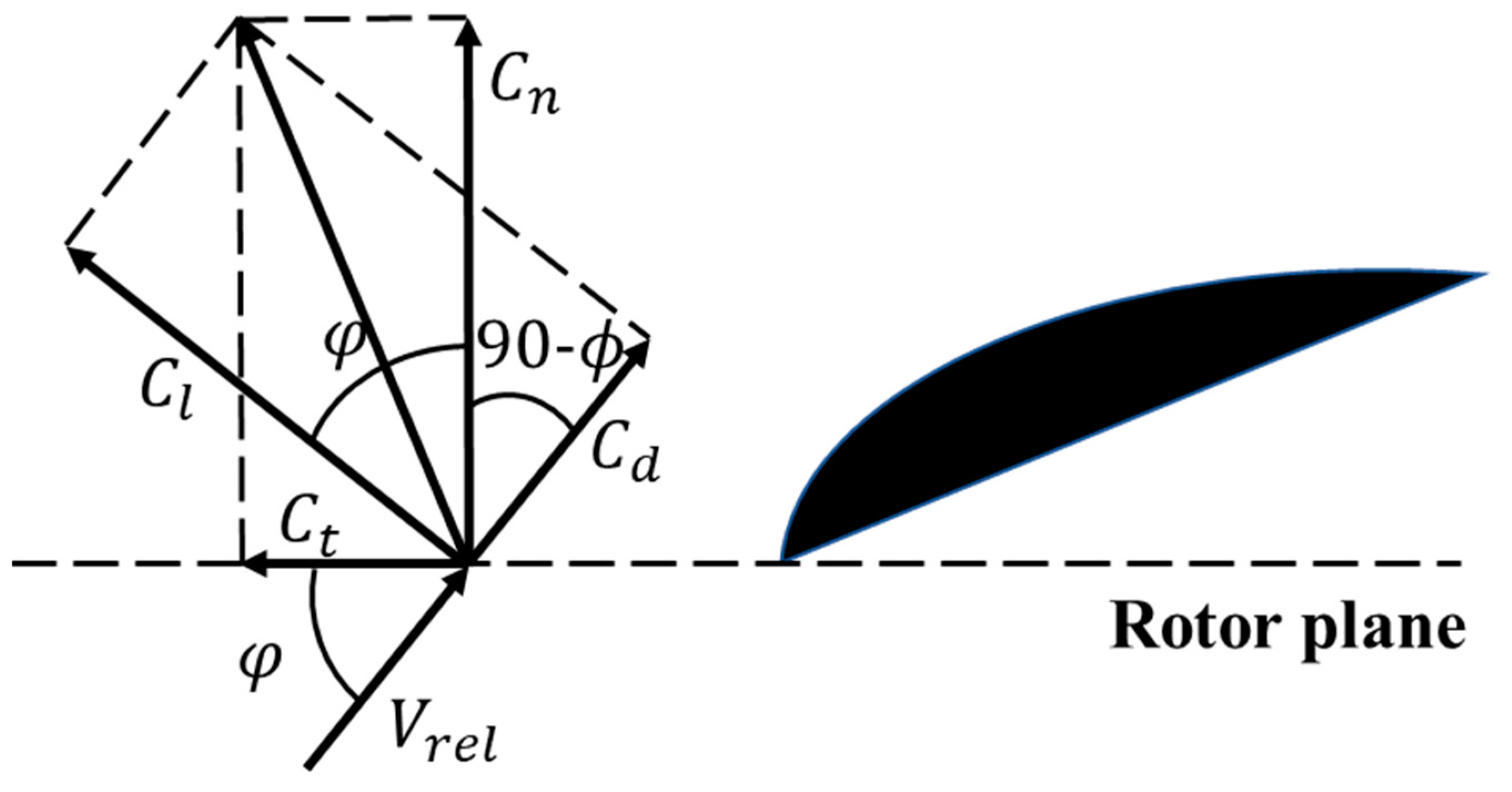
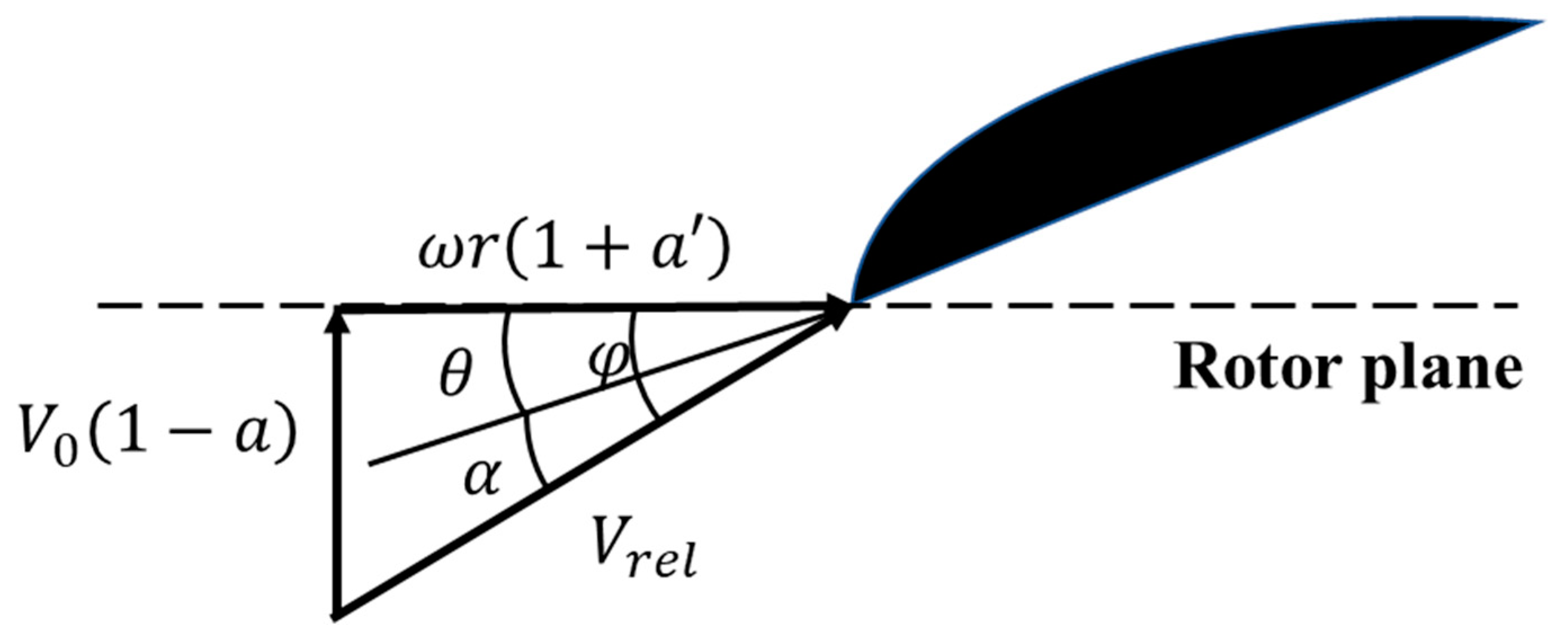
3.1. Aerodynamic Calculation

The BEM theory is used to perform the aerodynamic calculation. The blade is discretized into several elements. The velocity and aerodynamics on the blade element are shown in Figure 1 and Figure 2. The aerodynamics on each element can be obtained via the theorem of momentum. The aerodynamic thrust and torque on the whole rotor can be calculated via radial integration.
The iterative steps of the methodology can be expressed as follow [25]:
A. Initialization of normal, tangential induction factors:
a = a = 0
B. Solve the angle of wind velocity:
ϕ = tan 1 ( 1 a ) V 0 ( 1 + a ) ω r
C. Solve the AOA:
α = ϕ θ = ϕ ( θ p + β )
D. Calculate the corresponding lift, drag coefficients C l ( α ) , C d ( α ) of the airfoil. Since the aerodynamic coefficients vary with the Reynolds number, it is needed in order to update C l ( α ) , C d ( α ) at each iterative step based on the rotational speeds, wind velocities, and radius of the blade element.
E. Solve the normal and tangential force coefficients:
Normal :   C n = C l c o s ϕ + C d s i n ϕ
Tangential :   C t = C l s i n ϕ C d c o s ϕ
F. Update the normal and tangential induction factors:
  Normal :   a = 1 4 s i n 2 ϕ σ C n + 1
Tangential :   a = 1 4 s i n ϕ c o s ϕ σ C t 1
G. Repeat the steps B–F until convergence ( a and a are not changing) and calculate a , a , ϕ , C n and C t ;
H. Solve the relative wind speed:
V r e l = V 0 ( 1 a ) sin ϕ
I. Solve the aerodynamic loads on the blade elements:
Thrust :   d T = 1 2 ρ a V r e l 2 c C n d r
Torque :   d Q = 1 2 ρ a V r e l 2 c C t r d r
J. The aerodynamic loads on the rotor can be calculated via the radial integration:
Thrust :   T = n R 1 R 2 d T
Torque :   Q = n R 1 R 2 d Q
Among Equations (11)–(22), ω is the rotational speed, V 0 is the inflow wind velocity, θ p is the pitch angle, β is the twist angle, θ is the local pitch angle, n is the number of blades, r is the radius of the blade element, σ = n c / 2 π r is the solidity, c is the chord, ρ a is the air density, R 1 is the radius of the hub, and R 2 is the radius of the rotor. Moreover, the tip/hub loss is included during the calculation, to consider their influences on aerodynamics. Additionally, Glauert’s correction is also employed under the conditions of high normal induction factors [26].

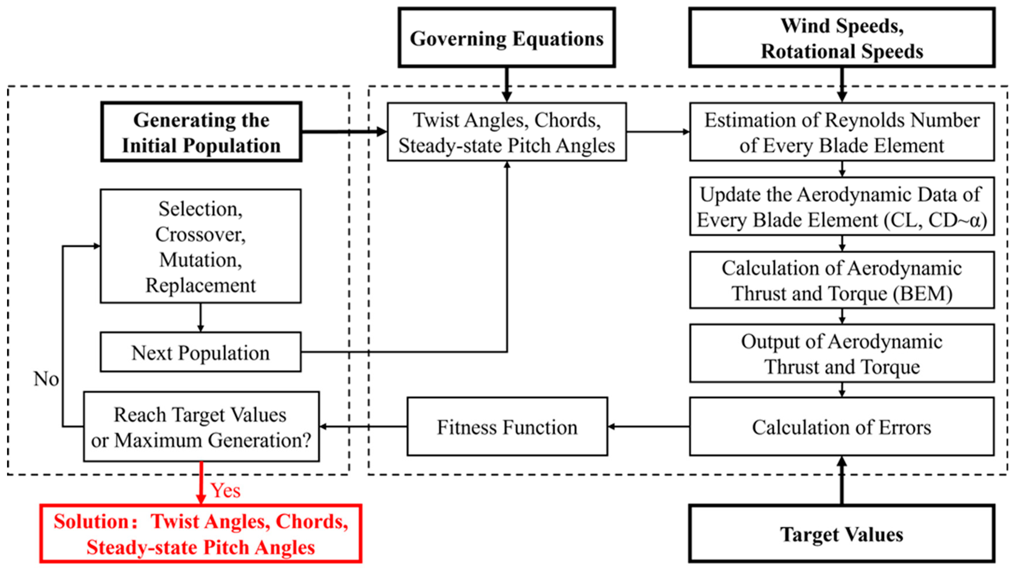
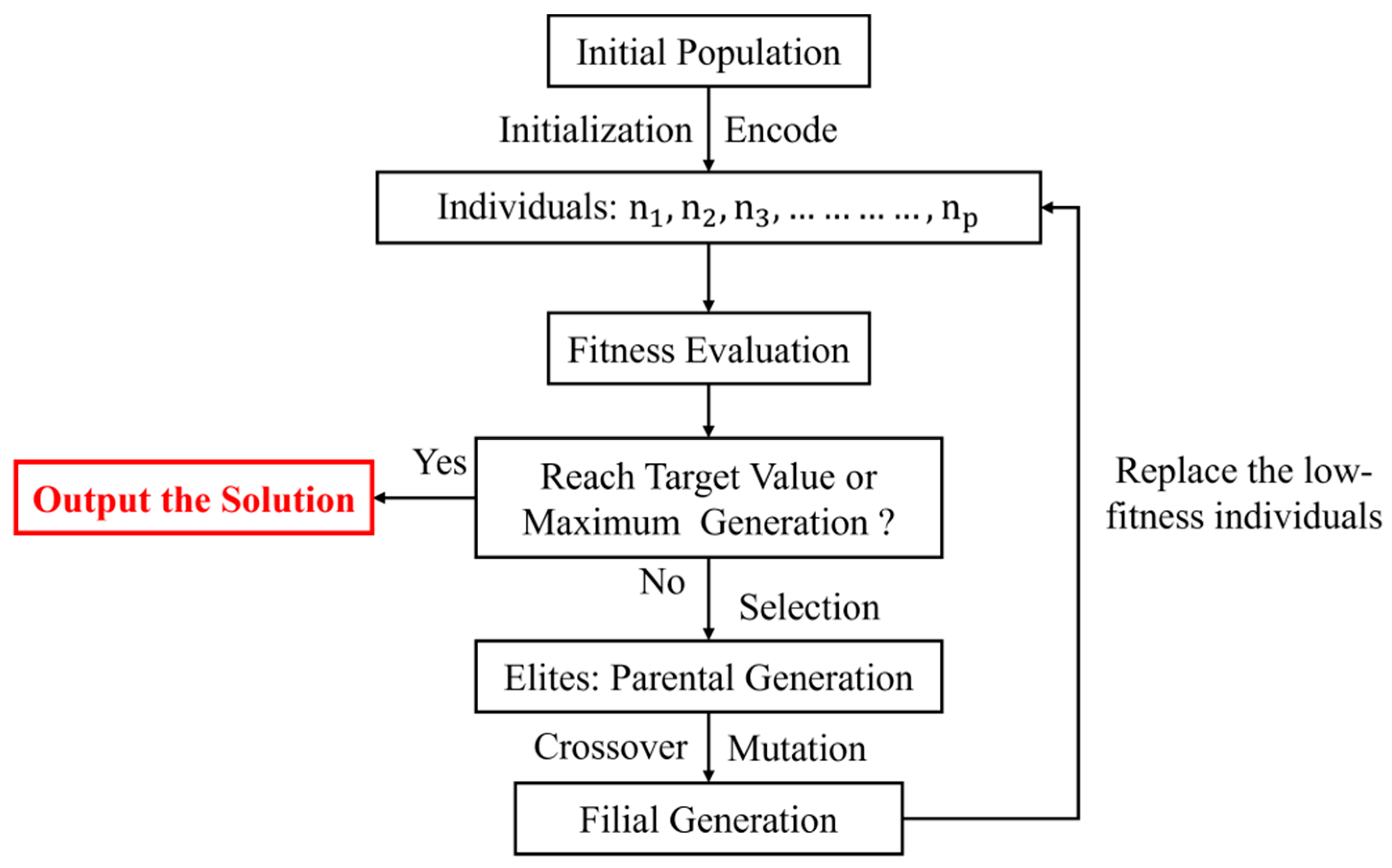
3.2. Genetic Algorithm

The genetic algorithm originated from the computer simulation of biological systems. It is a random global search optimization methodology which simulates the phenomena of crossover and mutation occurring in natural evolution. Starting from an initial population, the genetic algorithm generates a group of individuals more suitable for the constraints via random selection, crossover, and mutation operation, to mimic the evolution of the population. Therefore, the population continues to reproduce, evolve, and finally converge to a global optimal solution of the problem [27,28]. The schematic of GA is shown in Figure 3.

3.3. Design Variables and Fitness Functions

In this study, the BEM theory and GA are employed to achieve the aerodynamic equivalent design of rotor models. The schematic of the design process is shown in Figure 4. Under the model-scale conditions, the aerodynamic coefficients of airfoils are unstable and varies with the Reynolds number. Consequently, the lift and drag coefficients of the airfoil are updated at each iterative step to consider the variation in rotational speeds, wind speeds, and the radius of blade elements.
The twist angles, chords, and steady-state pitch angles are used as design variables. Moreover, the blade is discretized into elements and the governing equations of the radial distributions are employed to avoid break points. Similarly, the variation in the steady-state pitch angles with the wind speeds is also governed by the equation. The interpolation polynomials are adopted as governing equations mentioned above. In this way, the number of design variables could be significantly decreased, which is beneficial for the simplification of the design. The governing equations of the twist angles, chords, and pitch angles could be expressed as follow:
β ( r ) = i = 0 k ( j = 0 j i k r r j r i r j ) · β i
c ( r ) = i = 0 k ( j = 0 j i k r r j r i r j ) · c i
θ p ( V 0 ) = i = n m ( j = n j i m V 0 V 0 j V 0 i V 0 j ) · θ p i
Among the equations above, k is the radius of the blade elements, m is the number of wind speeds used for the design, and n is the serial number of rated wind speeds. In this study, the interpolation polynomials adopted are respectively cubic, quartic, and quintic. The results are compared for the analysis of accuracy and convergency.
Two fitness functions are used for the design, respectively, and are expressed as follows:
Fitness function f A
f A = w T · e T + w Q · e Q e T = m a x T m i T p i / T p i i = 1 ~ m e Q = m a x Q m i Q p n / Q p n i = n ~ m
Fitness function f B
f B = w T · e T + w Q · e Q e T = m a x T m i T p i / T p i i = 1 ~ m e Q = m a x Q m i Q p i / Q p i i = 1 ~ m
Among the equations above, w T and w Q are the weighting functions of thrust and torque errors, e T and e Q are the errors of the thrust and torque, T m and T P are the thrust of the rotor model and the prototype, Q m and Q p are the torque of the rotor model and the prototype, m is the number of the wind speeds used for the design, and n is the serial number of the rated wind speed.
Both fitness functions A and B require the thrust to be matched with the target values in the entire region between cut-in and cut-out wind speeds, so as to simulate the aerodynamic thrust accurately. As for the torque performance, function A only requires the variance of the model-scale torque with the wind speeds to be matched with that of the prototype, while function B requires the torque values of the model and the prototype to be accurately matched. The primary difference between these two fitness functions is the requirements of the torque performance. Fitness function A allows the model-scale active pitch control system to use the same strategy with the prototype. However, once fitness function B was satisfied, the parameters of the model control system could be directly scaled down from the prototype, which brings significant benefit to the design. In this study, the effects of these two fitness functions are both analyzed and compared.

4. Validation of the Aerodynamic Design

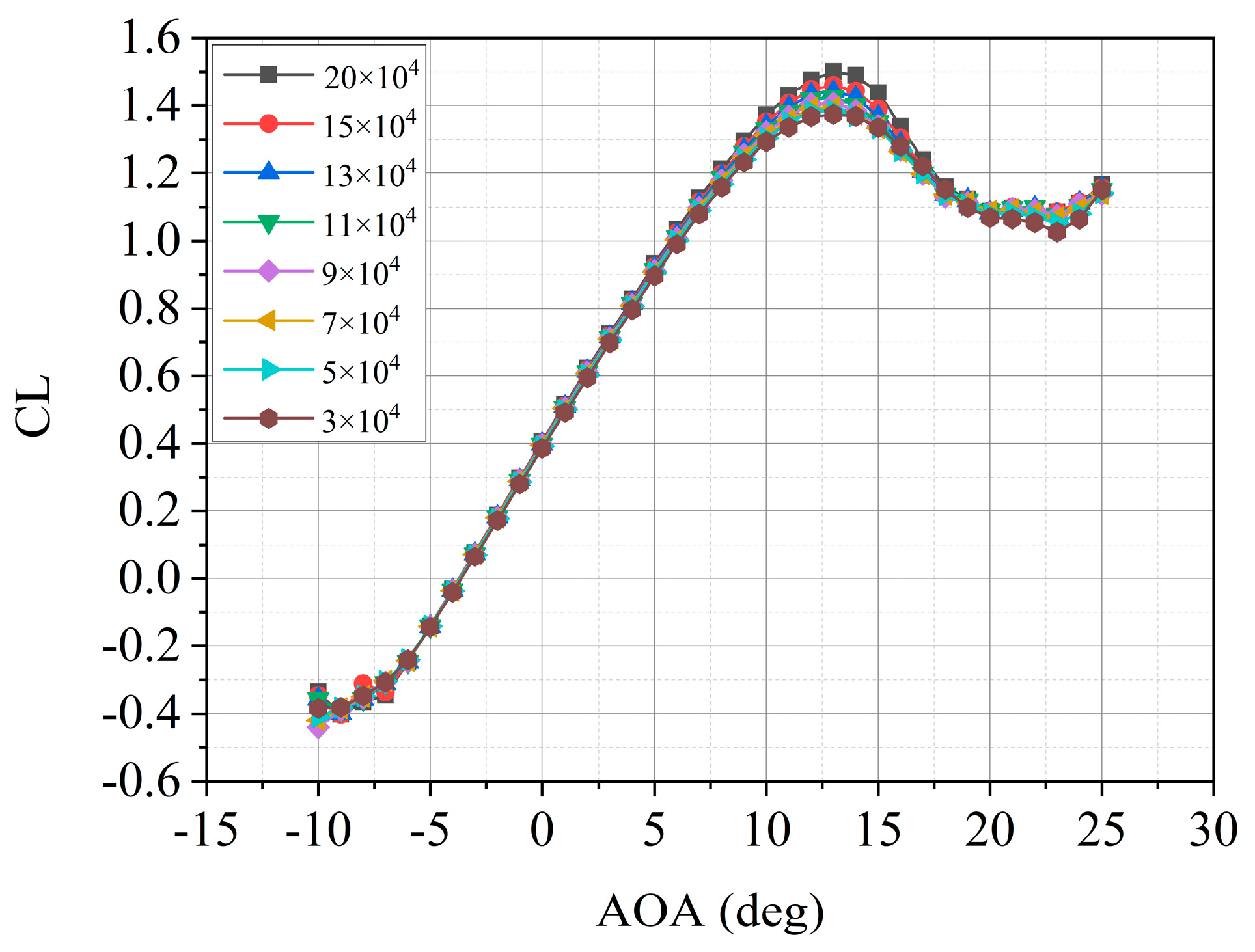
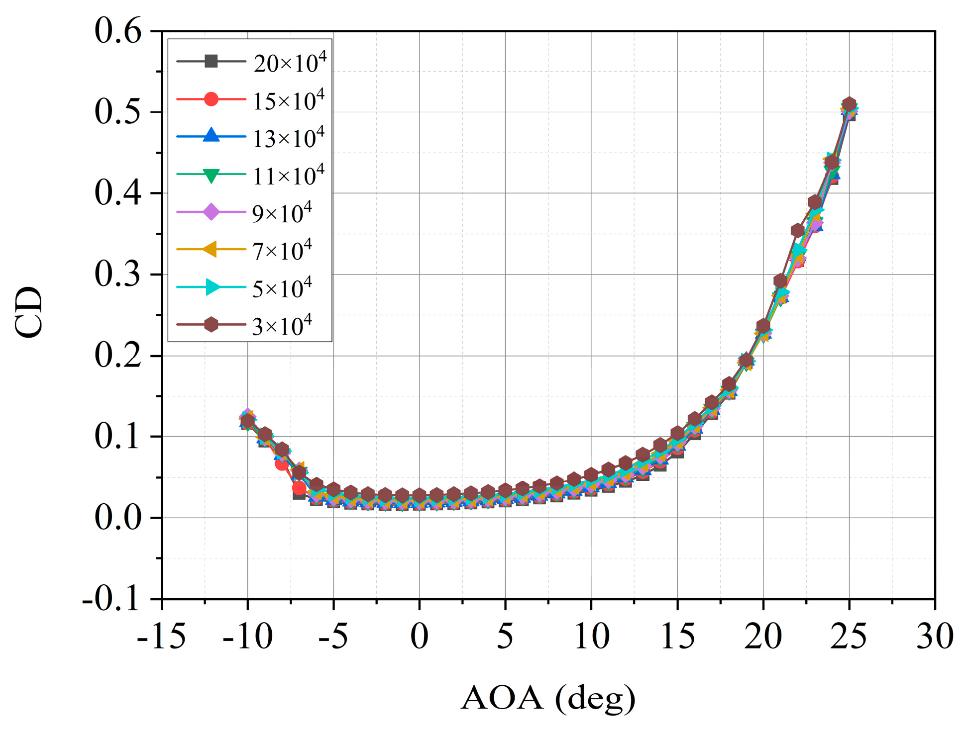
4.1. Selection of Airfoil

Under the model-scale conditions, the prototype airfoils cannot be used for the design of the rotor models. The low-Reynolds airfoil is adopted to redesign the rotor models, which can provide a good aerodynamic performance under model-scale conditions. According to previous investigations, the airfoil SD7032 is used for the design and the aerodynamic coefficients under different Reynolds number conditions, as shown in Figure 5 and Figure 6 [29]. As shown in the figures, there are significant differences in the lift and drag coefficients between different Reynolds numbers in the transition region between linear and stall AOAs, which proves that it is necessary to update the aerodynamic coefficients at each iterative step in the proposed design methodology.

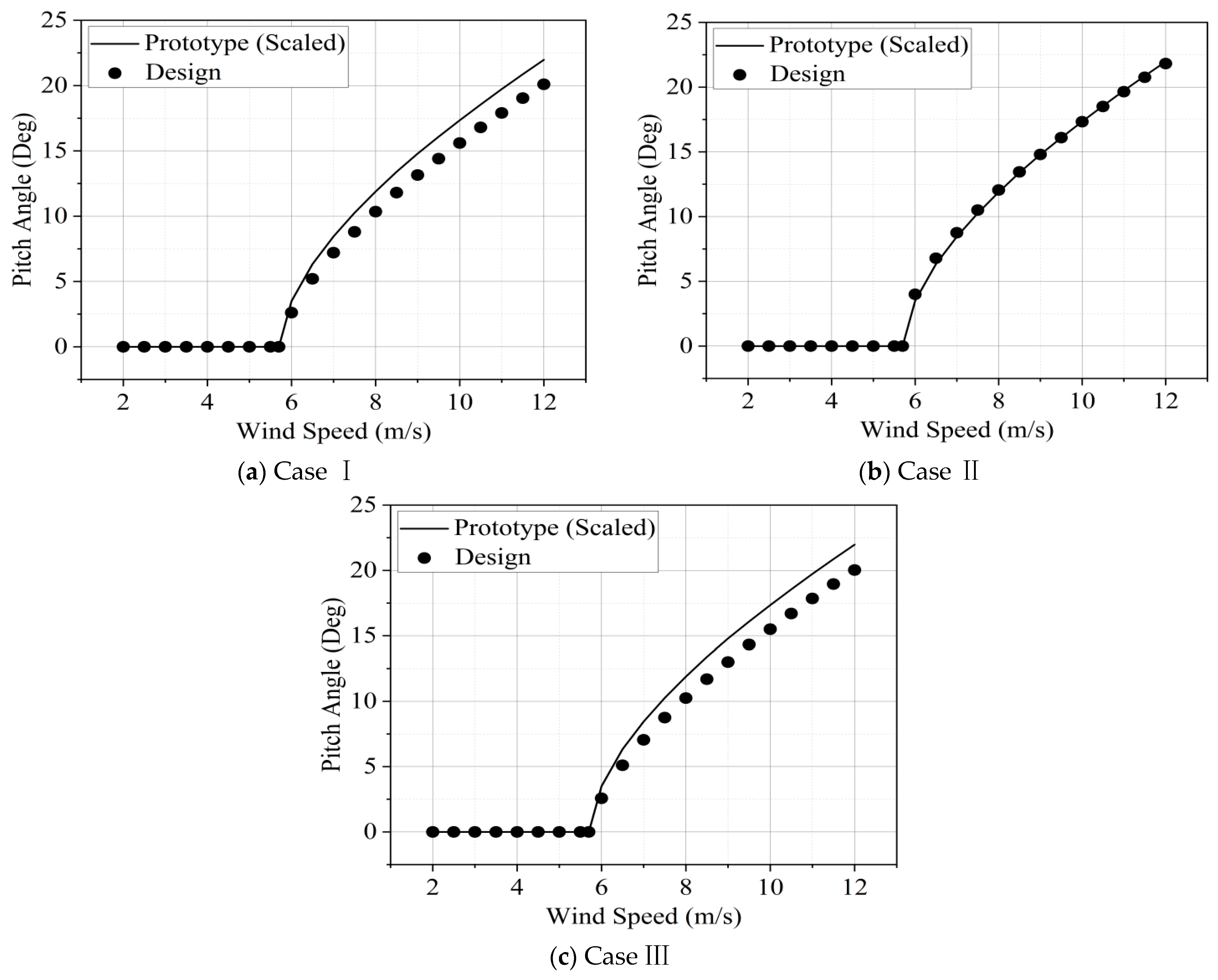
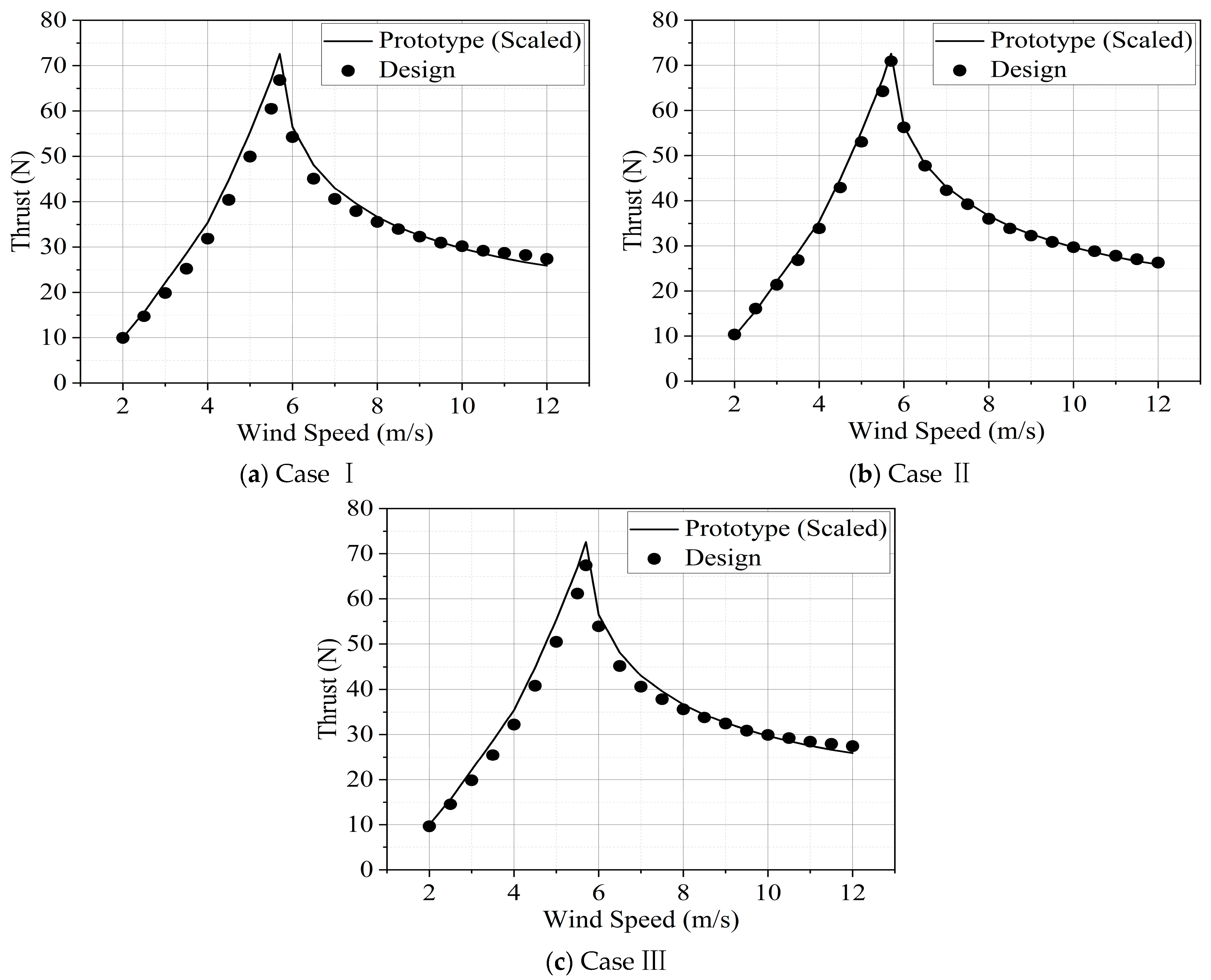
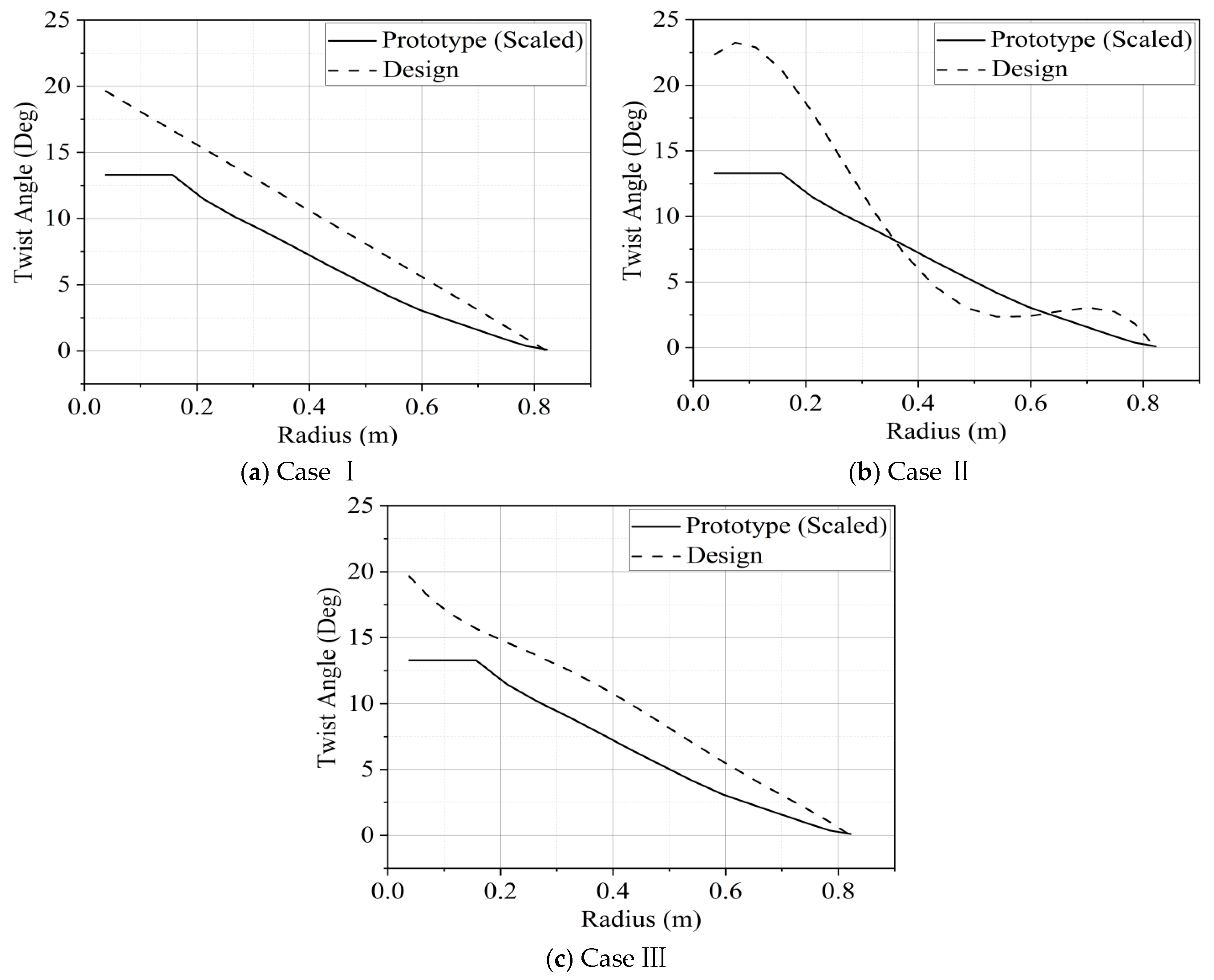
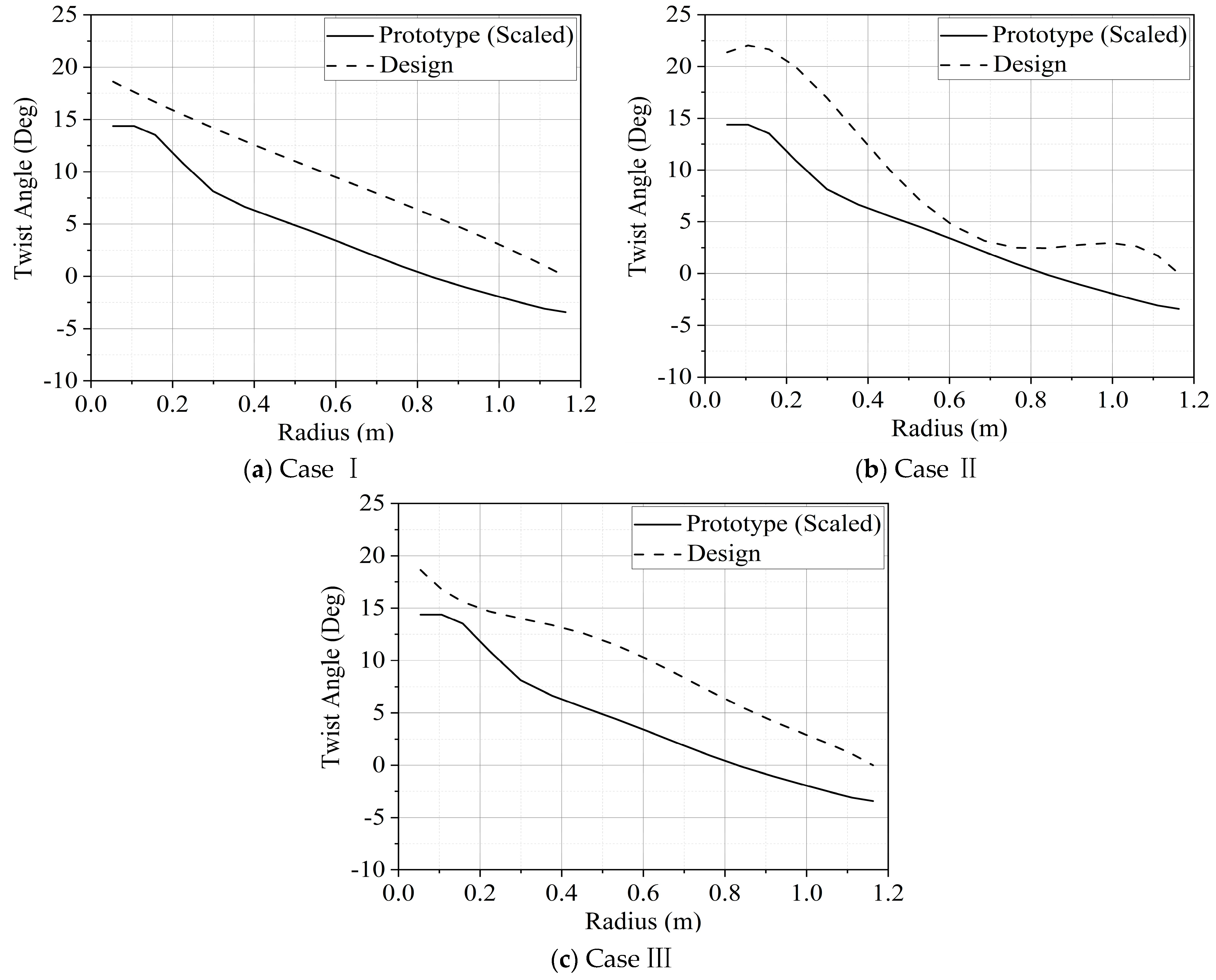
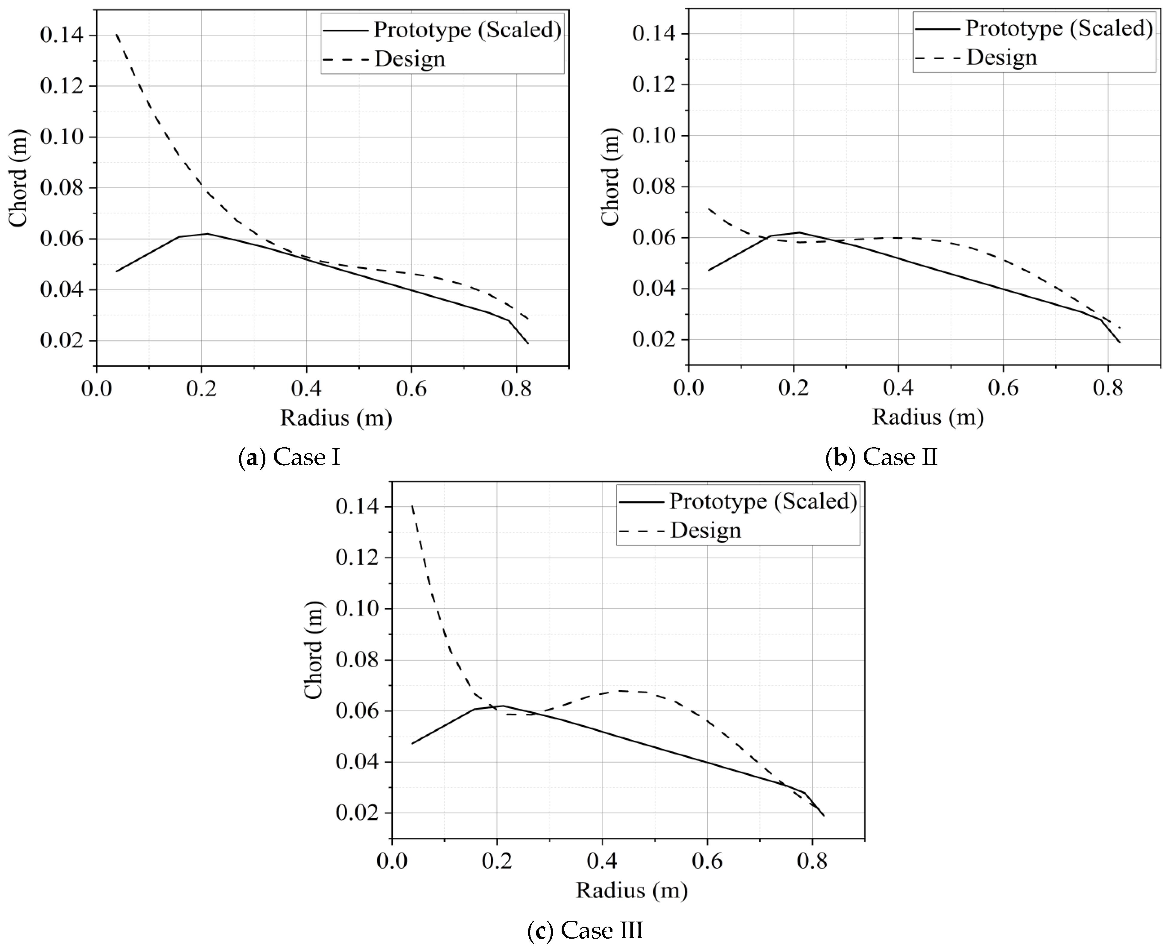
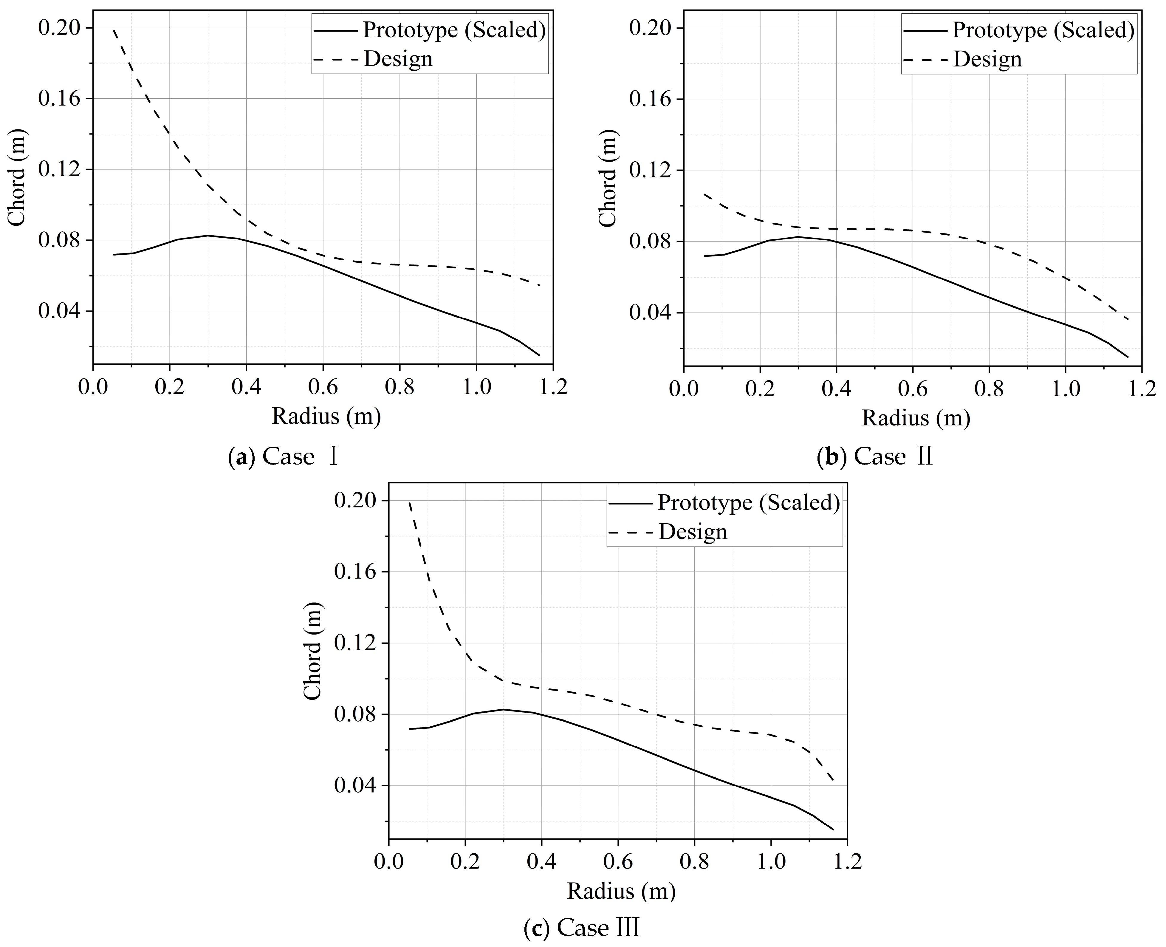
4.2. Output of Aerodynamic Design

Since the fitness function A is easier to be satisfied, it is used for validation in the design cases of Section 4.2 and Section 4.3. The twist angles, chords, and steady-state pitch angles are adopted as design variables. As mentioned before, the variations in the design variables with the radius or wind speeds are governed by the interpolation polynomials. The degrees of equations are respectively cubic, quartic, and quintic. The interpolating points consist of the tip, root, and equipartition points. The initial population is generated randomly and the number of individuals is set to 100. Furthermore, to exclude the influence of accidental factors, each case is run 10 times every time and the maximum iterative generation is set to 100. The best-fitting individuals are selected for validation. For clarity, the fitness function and degrees of interpolation polynomials used in each case of Section 4.2 and Section 4.3 are given in Table 3.
The radial distributions of the twist angles and chords are generated after the design iterations, as shown in Figure 7, Figure 8, Figure 9 and Figure 10. The scaled values of the prototype are also presented for comparison. It can be clearly seen that the radial distributions of the discretized elements are quite smooth and governed by the interpolation polynomials, which brings benefits to the aerodynamic calculation accuracy. It also shows that the overall distributions of the chords and twist angles in Case I and III are similar, while Case II is significantly different from other cases. It can be inferred that the above phenomenon might be caused by the local optimal solutions and it would be further analyzed in the following discussion.
Since the model-scale active pitch control strategies need to be redesigned for a similar dynamic performance, the steady-state pitch angles are not necessary to be the same with the prototype. Therefore, they could be used as design variables, so as to loosen the constraints. The variation in the steady-state pitch angles with the wind speeds is obtained, as shown in Figure 11 and Figure 12. The model-scale pitch angles of the three cases are all close to the target values, especially for Case II. Moreover, similar to the results of the twist angles and chords, the variation trends of the pitch angles in Cases I and III are almost the same. As mentioned above, it might be caused by the local optimal solutions.

4.3. Comparison of Aerodynamic Performance

To validate the aerodynamic performance, the model-scale thrust and torque of three cases are calculated by using Aerodyn of FAST (aerodynamic calculation module), as shown in Figure 13, Figure 14, Figure 15 and Figure 16, compared with the target values. Furthermore, for clear comparison, the statistics of thrust errors are also given in Table 4.
According to the comparison in Figure 13 and Figure 14, the model-scale thrust performance of each case is in satisfactory agreement with the prototype. Among them, the agreement between the model and the prototype of Case II is better than Cases I and III, especially in the region around the rated wind speed, which is also proved via the statistics in Table 4. The maximum and average errors of thrust in Case II are both below 5%, which is significantly lower than the other two cases. Combined with the previous analysis in Section 4.2, it is obvious that Cases I and III are stuck on the local optimal solutions. The primary difference between the three cases is the number of the interpolating points. If the interpolating points are too few, it is difficult to find the best-fitting individual. If the interpolating points are too many, the convergence of the design iteration is reduced. The influences of interpolation points are mainly caused by the limitations of GA, which would find the local optimal solution instead of the global optimal solution. Therefore, it can be inferred that the quartic interpolation polynomials in Case II provide the most suitable governing equation of the design variables for the rotor models, from the perspectives of both the accuracy and convergence.
Governed by fitness function A, the variance of the model-scale torque with the wind speeds reaches good agreement with the prototype. Although the aerodynamic torque has slight effects on the global coupled dynamic responses, it is the primary basis for the design of the active pitch control strategy. Similar variance of the torque with the wind speeds allows the model-scale active pitch control system to use the same logic with the prototype. In this way, it is not necessary for the model-scale torque values to be exactly equal to the target values, which will significantly reduce the design restrictions.
Based on the analysis above, it is approved that the aerodynamic design of the rotor model achieves satisfying results, combined with the quartic interpolation polynomials and fitness function A.

4.4. Comparison of Fitness Functions

As mentioned before, two fitness functions are introduced and the primary difference between them is the requirements of the torque performance. Function A only requires the variance of the model-scale torque with the wind speeds to be matched with the prototype, while Function B requires the torque values of the model and the prototype to be matched accurately. Function A is significantly easier to be satisfied and it has been proved to be effective. However, if satisfied, Function B can bring more convenience to the redesign of the active pitch control strategy. Therefore, Function B is also employed for the design and compared with Function A. Based on the discussion in Section 4.2 and Section 4.3, the NREL 5 MW rotor and the quartic interpolation polynomials are selected for case studies.
The aerodynamic thrust and torque are shown in Figure 17 and the statistics of the thrust errors are given in Table 5. Both these two fitness functions can generally lead to matched thrust performances with the prototype. However, Function A achieves lower errors of thrust in the region near the rated wind speed than Function B. It can be inferred that the evolution of the thrust performance during iterations is affected by the stricter constraints of the torque performance. As for the torque performance, it shows significant differences between the two fitness functions. As mentioned before, Function A achieves a similar variance of the model-scale torque with the prototype, which allows the redesigned active pitch control strategy to use the same logic with the prototype. Nevertheless, under the effects of Function B, not only do the torque values fail to match with the prototype, but also the variance of the torque is significantly different from the prototype, which cannot hold constant between the rated and cut-out wind speeds. It is indicated that the control logic of the prototype could not be used directly under model-scale conditions.
To sum up, based on the analysis above, Function A achieves better results than Function B and is more suitable for the aerodynamic design of the rotor model.

5. Conclusions

An innovative methodology of the aerodynamic equivalent design is proposed for the wind turbine rotor models in wind tunnel real-time hybrid model tests, based on the BEM theory and GA. The effectiveness of the design methodology is validated and the applicability of fitness functions is discussed. Several conclusions can be outlined as follows:
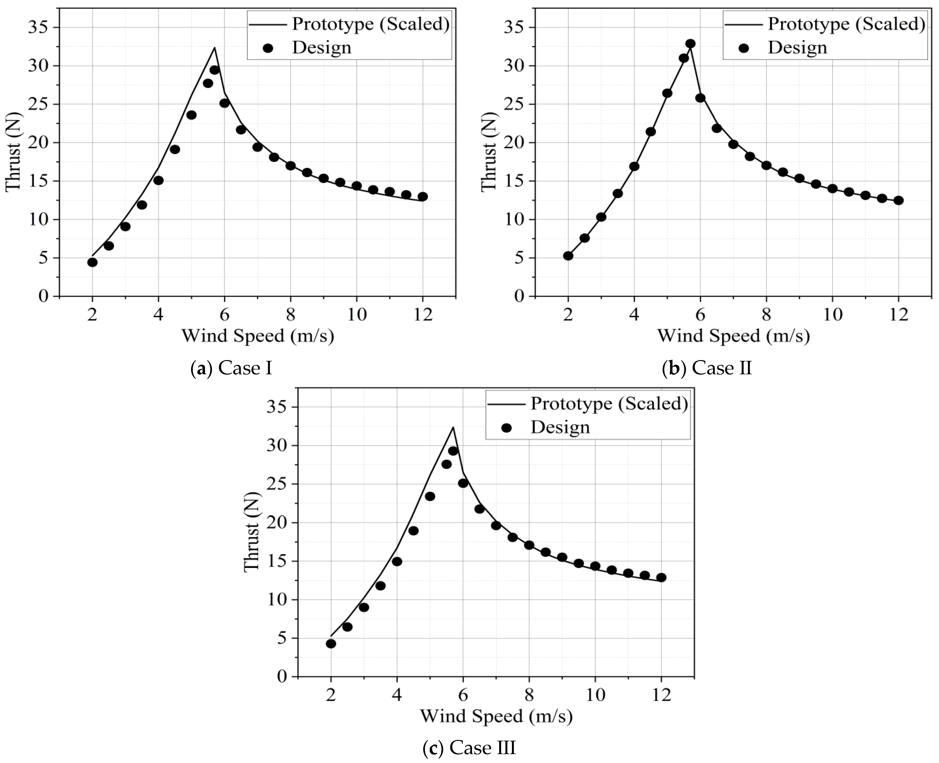
  • Based on the case studies of NREL 5 MW and DTU 10 MW, the model-scale aerodynamic thrust performance matches with the prototype accurately in the entire region between the cut-in and cut-out wind speeds, which allows the rotor model to provide a correct thrust at variant wind speeds. The maximum errors of the thrust between the model and the prototype are below 5%.
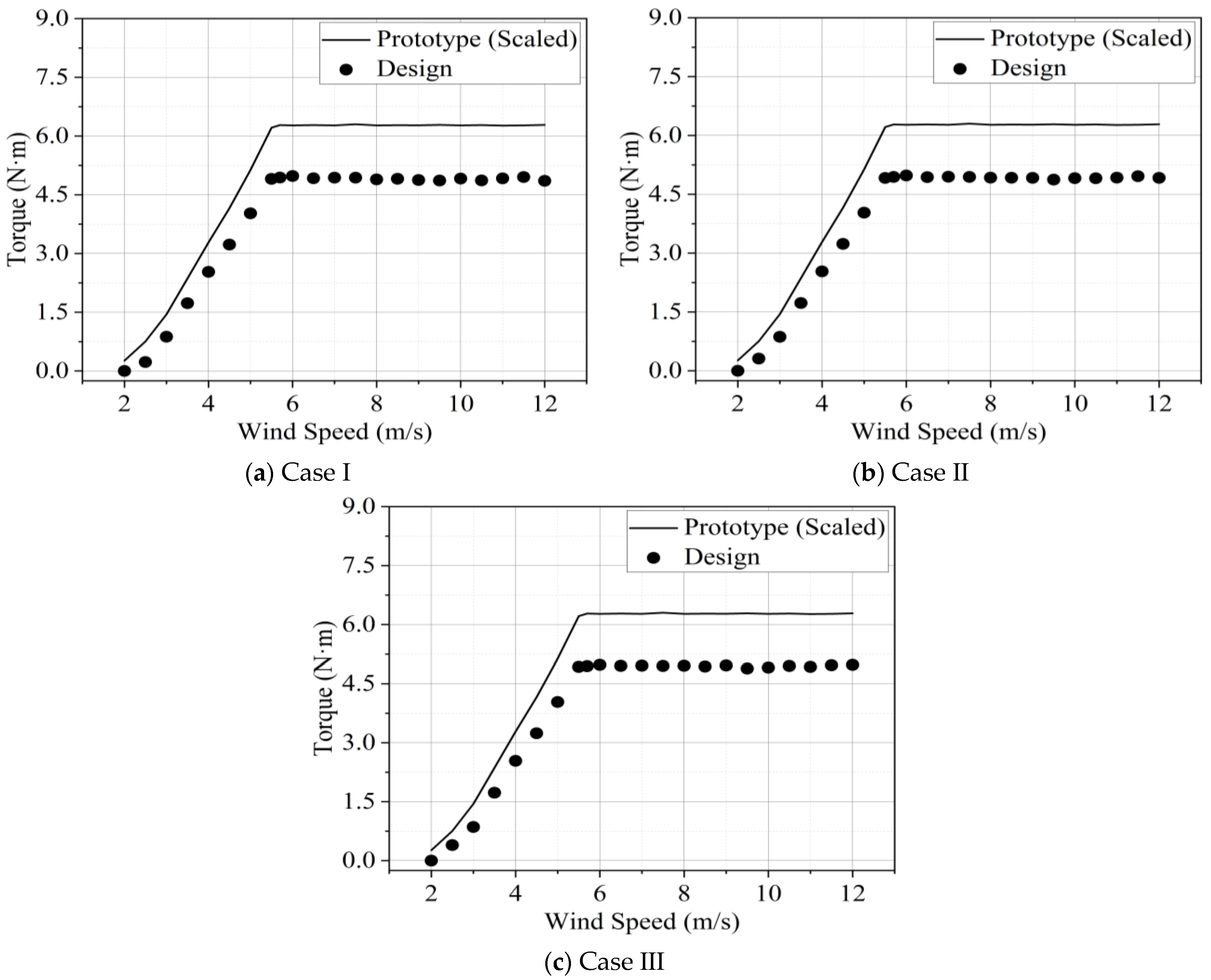
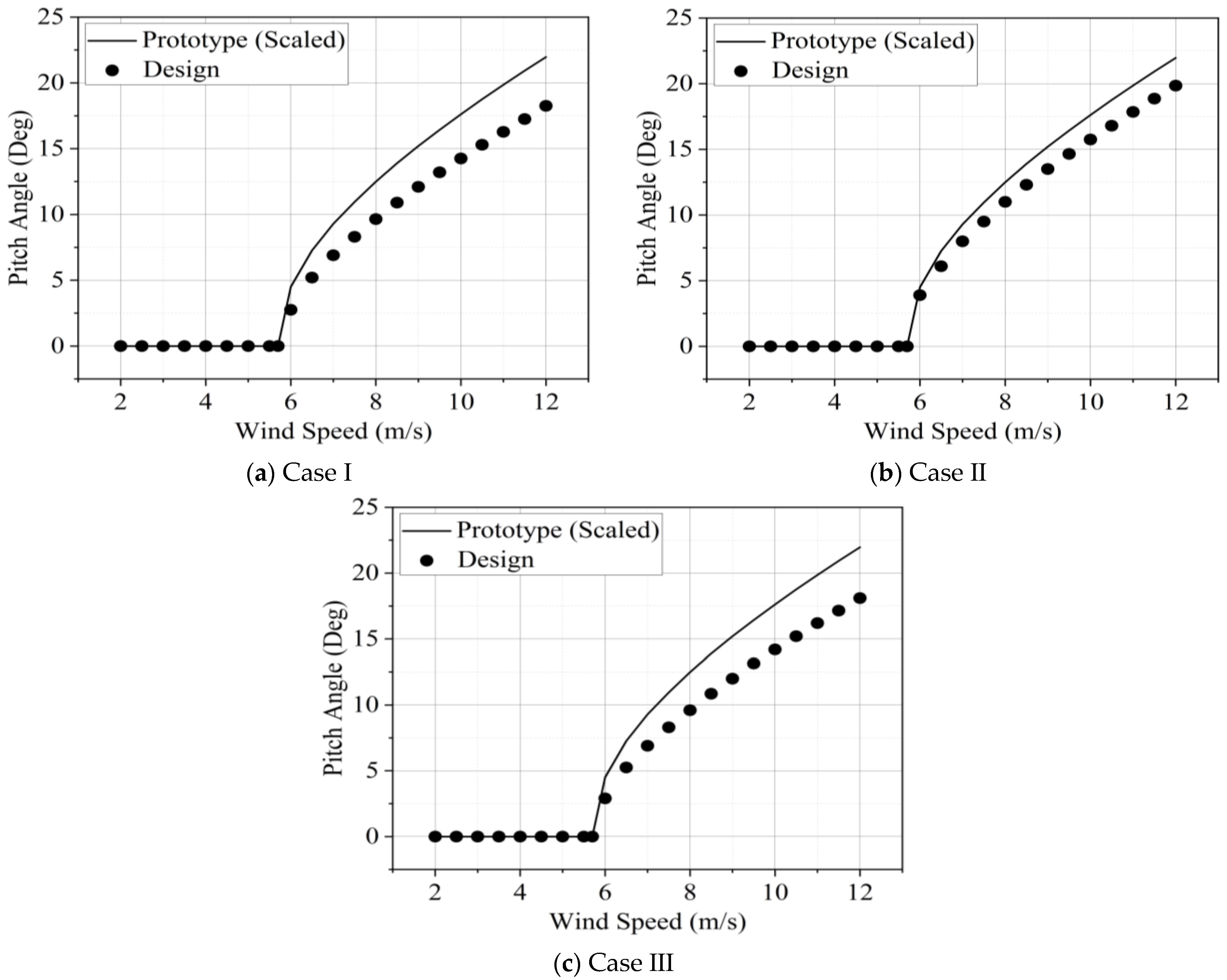
  • Based on the case studies of NREL 5 MW and DTU 10 MW, the variance of the aerodynamic torque with the wind speeds reaches good agreement between the model and the prototype, which allows the redesigned active pitch control strategy to use the same logic as the prototype.
  • Based on the case studies of NREL 5 MW and DTU 10 MW, the degree of interpolation polynomials used for the governing equations of the design variable has significant influences on the accuracy and convergence of the design iteration. The quartic interpolation polynomials could achieve satisfying results for the design, compared to the cubic and quintic cases.
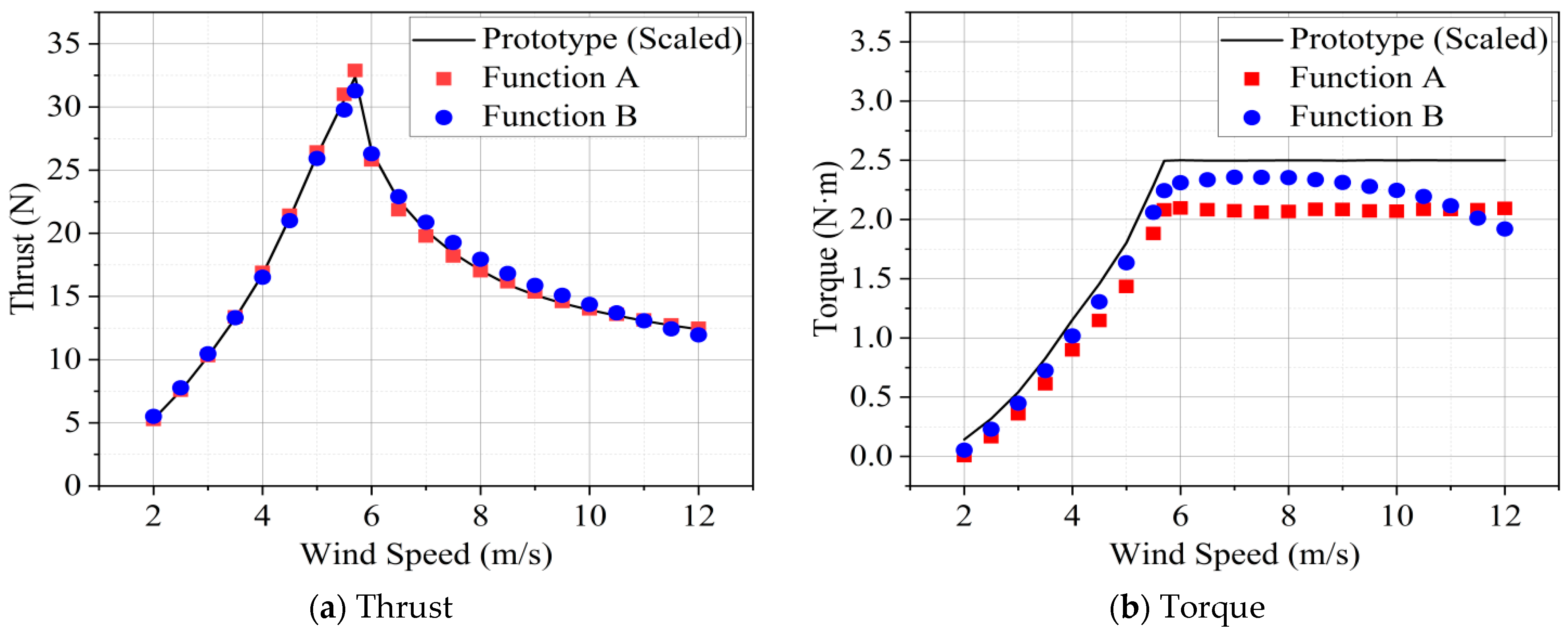
  • Based on the case studies of NREL 5 MW with quartic interpolation polynomials, the fitness Function A achieves better results than Function B and the maximum errors of thrust are respectively 3.28% and 5.56%, which indicates that function A is more suitable for the aerodynamic design of the rotor model. The requirement of the matched torque values is too strict to be reached and the accuracy of the thrust performance will be reduced.
According to the results, compared with the previous design methodology of the aerodynamic equivalent rotor model, the proposed methodology in this paper can achieve thrust and torque equivalence simultaneously within the whole wind speed region, rather than thrust equivalence under certain wind speed conditions. In summary, it can be proved that the proposed methodology is effective and will provide an essential support for the real-time hybrid model tests of FOWTs in wind tunnels. For future research, the structural equivalence of the blade should also be taken into account, to obtain more accurate structural responses.

Author Contributions

Conceptualization, Y.M., C.C., G.Y., M.C.O., H.L., T.F.; methodology, Y.M., C.C., G.Y., M.C.O., H.L., T.F.; software, Y.M.; validation, Y.M.; formal analysis, Y.M.; investigation, Y.M., Chen, C., G.Y., M.C.O., H.L., T.F.; writing—original draft preparation, Y.M.; writing—review and editing, Y.M., C.C., G.Y., M.C.O., H.L., T.F.; visualization, Y.M.; supervision, T.F.; project administration, T.F.; funding acquisition, T.F.. All authors have read and agreed to the published version of the manuscript.

Funding

This study was financially supported by National Natural Science Foundation of China (Grant No. 52071145, 52001126); Natural Science Foundation of Guangdong Province, China (Grant No. 2022B1515020071); the Guangdong province science and technology project (Grant No. 2021A0505030006); Key-Area Research and Development Program of Guangdong Province (Grant No. 2020B1111010001); and the Fundamental Research Funds for the Central Universities (Grant No. 2023ZYGXZR029).

Data Availability Statement

Data are available upon request.

Conflicts of Interest

The authors declare no conflict of interest.

References

  1. Musial, W.; Spitsen, P.; Beiter, P.; Duffy, P.; Marquis, M.; Cooperman, A.; Hammond, R.; Shields, M. Offshore Wind Market Report: 2022 Edition; National Renewable Energy Lab. (NREL): Golden, CO, USA, 2022.
  2. Ma, Y.; Chen, C.; Fan, T.; Yan, X.; Lu, H. Research on motion inhibition method using an innovative type of mooring system for spar floating offshore wind turbine. Ocean Eng. 2021, 223, 108644. [Google Scholar] [CrossRef]
  3. Ma, Y.; Chen, C.; Fan, T.; Lu, H. Research on the dynamic behaviors of a spar floating offshore wind turbine with an innovative type of mooring system. Front. Energy Res. 2022, 10, 853448. [Google Scholar] [CrossRef]
  4. Ma, Y.; Chen, C.; Yan, X.; Shen, Y.; Fan, T. Analysis on Hydrodynamic Responses of a Spar Offshore Wind Turbine with an Innovative Type of Mooring System. In Proceedings of the ASME 2019 38th International Conference on Ocean, Offshore and Arctic Engineering, Glasgow, UK, 9–14 June 2019. [Google Scholar]
  5. Jonkman, J.M. Dynamics Modeling and Loads Analysis of an Offshore Floating Wind Turbine. Ph.D. Thesis, University of Colorado at Boulder, Boulder, CO, USA, 2007. [Google Scholar]
  6. Jonkman, B.; Jonkman, J. FAST v8. 16.00; National Renewable Energy Laboratory: Golden, CO, USA, 2016; Volume 1355.
  7. Shen, Y.; Zhao, X.; Li, X. State of the art in dynamic modeling and load analysis of offshore floating wind turbines. J. Hunan Univ. Sci. Technol. (Nat. Sci. Ed.) 2017, 32, 23–31. [Google Scholar]
  8. Hansen, M.O.L.; Sørensen, J.N.; Voutsinas, S.; Sørensen, N.; Madsen, H.A. State of the art in wind turbine aerodynamics and aeroelasticity. Prog. Aerosp. Sci. 2006, 42, 285–330. [Google Scholar] [CrossRef]
  9. Browning, J.R.; Jonkman, J.; Robertson, A.; Goupee, A.J. Calibration and validation of a spar-type floating offshore wind turbine model using the FAST dynamic simulation tool. J. Phys. Conf. Ser. 2014, 555, 012015. [Google Scholar] [CrossRef]
  10. Coulling, A.J.; Goupee, A.J.; Robertson, A.N.; Jonkman, J.M.; Dagher, H.J. Validation of a FAST semi-submersible floating wind turbine numerical model with DeepCwind test data. J. Renew. Sustain. Energy 2013, 5, 023116. [Google Scholar] [CrossRef]
  11. Koo, B.; Goupee, A.J.; Lambrakos, K.; Lim, H.J. Model test correlation study for a floating wind turbine on a tension leg platform. In Proceedings of the ASME 2013 32nd International Conference on Ocean, Offshore and Arctic Engineering, Nantes, France, 9–14 June 2013. [Google Scholar]
  12. Martin, H.R.; Kimball, R.W.; Viselli, A.M.; Goupee, A.J. Methodology for wind/wave basin testing of floating offshore wind turbines. J. Offshore Mech. Arct. Eng. 2014, 136, 020905. [Google Scholar] [CrossRef]
  13. Adam, F.; Myland, T.; Dahlhaus, F.; Großmann, J. Scale tests of the GICON®-TLP for wind turbines. In Proceedings of the ASME 2014 33rd International Conference on Ocean, Offshore and Arctic Engineering, San Francisco, CA, USA, 8–13 June 2014. [Google Scholar]
  14. Chen, J.; Hu, Z.; Wan, D.; Xiao, Q. Comparisons of the dynamical characteristics of a semi-submersible floating offshore wind turbine based on two different blade concepts. Ocean Eng. 2018, 153, 305–318. [Google Scholar] [CrossRef]
  15. Duan, F.; Hu, Z.; Liu, G.; Wang, J. Experimental comparisons of dynamic properties of floating wind turbine systems based on two different rotor concepts. Appl. Ocean Res. 2016, 58, 266–280. [Google Scholar] [CrossRef]
  16. Belloli, M.; Bayati, I.; Facchinetti, A.; Fontanella, A.; Giberti, H.; La Mura, F.; Taruffi, F.; Zasso, A. A hybrid methodology for wind tunnel testing of floating offshore wind turbines. Ocean Eng. 2020, 210, 107592. [Google Scholar] [CrossRef]
  17. Fontanella, A.; Bayati, I.; Taruffi, F.; Mura, F.; Facchinetti, A.; Belloli, M. A 6-DOFs hardware-in-the-loop system for wind tunnel tests of floating offshore wind turbines. In Proceedings of the International Conference on Offshore Mechanics and Arctic Engineering, Glasgow, UK, 9–14 June 2019. [Google Scholar]
  18. Bayati, I.; Belloli, M.; Bernini, L.; Zasso, A. Aerodynamic design methodology for wind tunnel tests of wind turbine rotors. J. Wind Eng. Ind. Aerodyn. 2017, 167, 217–227. [Google Scholar] [CrossRef]
  19. Bayati, I.; Belloli, M.; Bernini, L. Qualification of Innovative Floating Substructures for 10 MW Wind Turbines and Water Depths Greater than 50m: LIFES50+ D3. 1 AeroDyn Validated Model; Technical Report; Politecnico di Milano: Milan, Italy, 2016. [Google Scholar]
  20. Méndez, J.; Greiner, D. Wind blade chord and twist angle optimization using genetic algorithms. In Proceedings of the 5th International Conference on Engineering Computational Technology, Las Palmas de Gran Canaria, Spain, 12–15 September 2006; pp. 12–15. [Google Scholar]
  21. Eke, G.B.; Onyewudiala, J.I. Optimization of wind turbine blades using genetic algorithm. Glob. J. Res. Eng. 2010, 10, 22–26. [Google Scholar]
  22. Yang, Y.; Li, C.; Zhang, W.; Yang, J.; Ye, Z.; Miao, W.; Ye, K. A multi-objective optimization for HAWT blades design by considering structural strength. J. Mech. Sci. Technol. 2016, 30, 3693–3703. [Google Scholar] [CrossRef]
  23. Jonkman, J.; Butterfield, S.; Musial, W.; Scott, G. Definition of a 5-MW Reference Wind Turbine for Offshore System Development; National Renewable Energy Lab. (NREL): Golden, CO, USA, 2009.
  24. Bak, C.; Zahle, F.; Bitsche, R.; Kim, T.; Yde, A.; Henriksen, L.C.; Hansen, M.H.; Blasques, J.P.A.A.; Gaunaa, M.; Natarajan, A.; et al. The DTU 10-MW reference wind turbine. In Proceedings of the Danish Wind Power Research 2013, Fredericia, Denmark, 27–28 May 2013. [Google Scholar]
  25. Moriarty, P.J.; Hansen, A.C. AeroDyn Theory Manual; National Renewable Energy Lab.: Golden, CO, USA, 2005.
  26. Hansen, M. Aerodynamics of Wind Turbines; Routledge: London, UK, 2015. [Google Scholar]
  27. Holland, J.H. Genetic algorithms. Sci. Am. 1992, 267, 66–73. [Google Scholar] [CrossRef]
  28. Sivanandam, S.N.; Deepa, S.N. Genetic algorithms. In Introduction to Genetic Algorithms; Springer: Berlin/Heidelberg, Germany, 2008; pp. 15–37. [Google Scholar]
  29. Selig, M.S. Summary of Low-Speed Airfoil Data; SOARTECH Publications: Virginia Beach, VA, USA, 1995. [Google Scholar]
Figure 1. Velocity on blade element.
Jmse 12 00001 g001
Figure 2. Aerodynamic on blade element.
Jmse 12 00001 g002
Figure 3. Schematic of GA.
Jmse 12 00001 g003
Figure 4. Schematic of design process.
Jmse 12 00001 g004
Figure 5. Lift coefficients [29].
Jmse 12 00001 g005
Figure 6. Drag coefficients [29].
Jmse 12 00001 g006
Figure 7. Radial distributions of twist angles (NREL 5 MW).
Jmse 12 00001 g007
Figure 8. Radial distributions of twist angles (DTU 10 MW).
Jmse 12 00001 g008
Figure 9. Radial distributions of chords (NREL 5 MW).
Jmse 12 00001 g009
Figure 10. Radial distributions of chords (DTU 10 MW).
Jmse 12 00001 g010
Figure 11. Steady-state pitch angles (NREL 5 MW).
Jmse 12 00001 g011
Figure 12. Steady-state pitch angles (DTU 10 MW).
Jmse 12 00001 g012
Figure 13. Aerodynamic thrust (NREL 5 MW).
Jmse 12 00001 g013
Figure 14. Aerodynamic thrust (DTU 10 MW).
Jmse 12 00001 g014
Figure 15. Aerodynamic torque (NREL 5 MW).
Jmse 12 00001 g015
Figure 16. Aerodynamic torque (DTU 10 MW).
Jmse 12 00001 g016
Figure 17. Aerodynamic performance (governed by fitness functions A and B).
Jmse 12 00001 g017
Table 1. Scale factors ( λ ρ = 1 ).
FactorExpressionValues
Length λ l 1/75
Velocity λ V 1/2
Mass λ ρ λ l 3 1/421,875
Time λ l / λ V 1/37.5
Frequency λ V / λ l 37.5
Acceleration λ V 2 / λ l 18.75
Force λ ρ λ V 2 λ l 2 1/22,500
Moment λ ρ λ V 2 λ l 3 1/1,687,500
Table 2. Specifications of rotors.
ParametersValues
NREL 5 MWDTU 10 MW
PrototypeModelPrototypeModel
Cut-in wind speed3 m/s1.5 m/s4 m/s2 m/s
Rated wind speed11.4 m/s5.7 m/s11.4 m/s5.7 m/s
Cut-out wind speed25 m/s12.5 m/s25 m/s12.5 m/s
Hub diameters3 m0.04 m5.6 m0.075 m
Rotor diameters126 m1.68 m178.3 m2.38 m
Cut-in rotational speed6.9 rpm258.75 rpm6 rpm225 rpm
Cut-out rotational speed12.1 rpm453.75 rpm9.6 rpm360 rpm
Table 3. Design cases.
CaseFitness FunctionDegree of Interpolation Polynomial
IACubic
IIQuartic
IIIQuintic
Table 4. Statistics of thrust errors (Case I, II, and III).
CaseNREL 5 MWDTU 10 MW
MaximumAverageMaximumAverage
I16.57%6.32%11.72%5.51%
II3.28%1.09%4.11%2.21%
III19.18%6.55%11.01%5.38%
Table 5. Statistics of the thrust errors (Fitness function A, B).
Fitness FunctionMaximumAverage
A3.28%1.09%
B5.56%2.70%
Disclaimer/Publisher’s Note: The statements, opinions and data contained in all publications are solely those of the individual author(s) and contributor(s) and not of MDPI and/or the editor(s). MDPI and/or the editor(s) disclaim responsibility for any injury to people or property resulting from any ideas, methods, instructions or products referred to in the content.

