Article

Coupled Dynamic Characteristics of a Spar-Type Offshore Floating Two-Bladed Wind Turbine with a Flexible Hub Connection

1
School of Ocean Engineering and Technology, Sun Yat-Sen University & Southern Marine Science and Engineering Guangdong Laboratory (Zhuhai), Zhuhai 519082, China
2
Key Laboratory of Comprehensive Observation of Polar Environment (Sun Yat-Sen University), Ministry of Education, Zhuhai 519082, China
3
China Energy Engineering Group Guangdong Electric Power Design Institute Co., Ltd., Guangzhou 510799, China
*
Author to whom correspondence should be addressed.
J. Mar. Sci. Eng. 2024, 12(4), 547; https://doi.org/10.3390/jmse12040547
Submission received: 21 February 2024 / Revised: 13 March 2024 / Accepted: 19 March 2024 / Published: 25 March 2024
(This article belongs to the Special Issue Innovative Development of Offshore Wind Technology)

Abstract

:
To reduce manufacturing, transportation, lifting and maintenance costs of increasingly larger and larger floating wind turbines, a Spar-type floating two-bladed wind turbine based on the 5 MW OC3-Hywind floating wind turbine model from the National Renewable Energy Laboratory (NREL) is studied in this paper. The two-bladed wind turbine can cause serious problems with large dynamic loads, so a flexible hub connection was introduced between the hub mount and nacelle carrier to alleviate the dynamic effect. The paper focuses on studying the dynamic responses of the proposed Spar-type floating two-bladed wind turbine with a flexible hub connection at rated and extreme environmental conditions. Fully coupled time-domain simulations are carried out by integrating aerodynamic loads on blades, hydrodynamic loads on the spar, structural dynamics of the tower, blades and mooring lines, control system and flexible hub connection. The analysis results show that the application of a flexible hub connection between the hub mount and nacelle carrier can make a contribution to enable the Spar-type floating two-bladed wind turbine to effectively dampen the motion of the floating platform, while significantly reducing the tower load and blade deflection.

1. Introduction

With the growing severity of environmental and energy issues, humans have become increasingly aware of the crucial significance of developing clean energy [1,2,3,4]. Drawing upon the statistical information provided by the International Energy Agency (IEA), it is evident that the renewable energy market share is experiencing a consistent rise, with wind power contributing significantly, accounting for 36% of the overall increase [5,6,7,8,9,10,11]. In order to capture offshore wind energy, many countries and institutions are focusing on floating offshore wind turbines. However, the cost issue of offshore wind power is one that cannot be ignored [12,13,14,15].
The three-blade turbine is currently the most prevalent type of wind turbine. Nevertheless, as the capacity of single turbines surpasses 10 MW, the challenges associated with the high manufacturing, transportation, and installation costs of three-blade turbines have become increasingly prominent [16,17,18,19,20,21]. Therefore, the two-blade wind turbine came to people’s vision [22]. A two-bladed wind turbine has one less blade than a three-bladed wind turbine. Lowering the number of blades by one would significantly cut down on manufacturing costs [18,23]. Simultaneously, the two-bladed design facilitates transportation and may eliminate the need for on-site assembly, thereby further reducing transportation, lifting, and maintenance costs [24,25,26]. In order to reduce the cost, studying two-blade floating offshore wind turbines holds remarkable economic significance.
The main factors restricting the development of two-blade wind turbines were mainly related to higher rotation speed and dynamic loads. At the same speed, the output power of a two-blade wind turbine will be lower than that of a three-blade wind turbine. Therefore, higher wind speed is needed to ensure that the output of two-blade wind turbines meets the requirements, and the blade tip speed is much higher. When the blade tip speed increases, the noise generated by blade operation will increase rapidly [27,28,29,30]. This has hindered the development and application of onshore two-blade wind turbines. For offshore wind power, however, loud noise seems less unacceptable. The lower manufacturing costs, transport costs and installation costs of two-blade wind turbines make them attractive in the offshore wind industry. Under the influence of extreme wind conditions (such as typhoons), the load of the two-blade wind turbine is smaller than that of the three-blade wind turbine, and its survival ability is also better than that of the three-blade wind turbine.
One key disadvantage of two-bladed wind turbines operating at the same power level is that the bending moments on the blade hub and tower base are greater for each individual rotor blade, potentially leading to fatigue loads on the turbines. Consequently, in comparison to the three-bladed design, two-bladed rotors necessitate a teetering hub to mitigate excessive shocks on the turbine during strong winds [31,32,33]. Load reduction in two-blade turbine structures is a critical issue that deserves significant attention. Ugurcan Eroglu et al. proposed a method to study the problem of a large deflection straight beam with small amplitude vibration. Considering the effects of axial tension, shear deformation and moment of inertia, the small amplitude free vibration differential equations of deflection configuration are established [34]. Mertol Tüfekci et al. studied the complexity of the mechanical properties of aircraft engine fan blades made of foam of Ti-6Al-4V by means of numerical simulation [35]. Mohammadi et al. developed a two-blade wind turbine model with rigid rotors and teetered rotors in FAST and discussed and compared their power quality and structural load [36]. Klein et al. used CFD and MBS-BEM to study the new passive load reduction concept of the 3.4 MW two-blade wind turbine, and the results show that the load on the wind turbine support structure is significantly reduced [37]. Taking Skywind 3.4 MW two-blade wind turbine as a reference, Luhmann et al. proposed a concept to reduce the load by installing elastic coupling components in the hub (Figure 1) and carried out a numerical simulation. The multi-body simulation solver Simpack was used to conduct parametric research on the stiffness and damping of the flexible hub [23].
In this paper, a Spar-type floating two-bladed wind turbine was designed, drawing inspiration from the 5 MW OC3-Hywind floating wind turbine model developed by the National Renewable Energy Laboratory (NREL). To solve the problem of the large dynamic load of the two-bladed wind turbine, we refer to Luhmann’s article on the concept of flexible hub connection, as shown in Figure 1. The flexible hub connection system is composed of several flexible couplings located between hub supports. These flexible couplings are more price-friendly and do not add additional costs to the wind turbine. At the same time, wind turbines can be independently assembled using a winch system without the need for external cranes [23]. A comparison is made between the time-domain dynamic responses of rigid and flexible connections, as well as a comparison of dynamic responses of the floating body in the time domain.

2. Theoretical Model

2.1. Dynamic Equation

The motion of an Offshore Floating Wind Turbine is subject to the coupling action of wave force, mooring system force and aerodynamic loads and the equations of motion of floating structures can be expressed as follows:
M + A x ¨ t + - k t   -   τ x ˙ t d τ + K m x , t + K h × t = F ext ( x , x ˙ , t )
where x t ,   x ˙ t ,   x ¨ ( t ) represent the displacement, velocity and acceleration of the floating structure, respectively; M denotes the mass matrix of the system, while A represents the added mass at infinite frequency. The retardation function k t   -   τ is derived from the frequency-dependent conversion of added mass and damping, thus encapsulating the fluid memory effect. Additionally, K m represents the nonlinear recovery matrix of the mooring system, and K h stands for the hydrostatic recovery matrix of the floating structure. In essence, the left-hand side of the equation captures the dynamic motion of the floating body, while the right-hand side accounts for the exciting force acting on the system.
F ext x , x ˙ , t = F Aero x , x ˙ , t + F FK t + F D t + F Drag ( x ˙ , t )
Exciting force mainly includes the following aspects: F A e r o is the aerodynamic force; F FK and F D are the F−K force and the diffraction force, respectively; F Drag is the viscous force. The Morrison equation is used to estimate the viscous resistance on floating structures [38].

2.2. Equation of the Teeter Movement

After adding the flexible hub connection, an equation of teetering motion is derived:
I ζ ¨ + ( B aer + B hub ) ζ ˙ + K cf + K pt + K hub ζ = M ( t )
where ζ is the teetering angle, I is the moment of inertia of the rotor about its center, M ( t ) is the teeter moment. The resisting and restoring moments of the teeter movement are caused by the spring constants K cf , K pt , and K hub . The resisting moments are caused by B aer and B hub [39].

2.3. Morison Equation

The viscous flow phenomenon should be taken into account in tackling the problem of wave loads received by spar platforms [40,41]. According to the Morison equation, the horizontal force dF on a strip of length dz of a vertical rigid circular cylinder can be written as:
dF = ρ π D 2 4 dz C M a 1 + ρ 2 C D Ddz | u | u
where ρ is the mass density of the water, D is the cylinder diameter, u and a 1 are the horizontal undisturbed fluid velocity and acceleration at the midpoint of the strip. The mass and drag coefficients, C M and C D , respectively, require empirical determination. The positive force direction is the same as the direction of wave propagation.
Then, the horizontal wave force on a cylinder can be obtained by integrating the horizontal force dF from z 1 to z 2 :
F = z 1 z 2 dF = z 1 z 2 ρ π D 2 4 C M a 1 dz + z 1 z 2 ρ 2 C D D | u | udz

2.4. Potential Theory

Assuming that the fluid is incompressible, irrotational, and inviscid. A velocity potential Φ can be employed to characterize the fluid velocity vector V ( x , y , z , t )   = ( u , v , w ) at a given point x   = ( x , y , z ) and time t in a stationary Cartesian coordinate system. The relationship between the velocity potential and the fluid velocity flow field is as follows:
V = Φ = Φ x i + Φ y j + Φ z k
where i , j and k are unit vectors along the x-, y- and z-axes, respectively.
Since water is incompressible, · V = 0 , the velocity potential can be represented as the Laplace equation as below:
2 Φ x 2 + 2 Φ y 2 + 2 Φ z 2 = 0
It is assumed that the only external force field is gravity, and the fluid is incompressible, irrotational, and inviscid. According to Bernoulli’s equation:
P + ρ gz + ρ Φ t + ρ 2 V · V = C
the pressure exerted by the potential flow can be determined accordingly. In the aforementioned equation, C represents an arbitrary function of time. We will incorporate the time dependency of C into the velocity potential while maintaining C as a constant. The corresponding linear force is computed by integrating the Bernoulli pressure over the object’s surface, retaining only the first-order terms in terms of the wave slope as follows:
F = - S B P n dS = - S B 0 Φ 1 t + 1 2 Φ 0 · Φ 1 ndS - S B P 0 ( α ( 1 ) × n ) dS
where α ( 1 ) is the rotation vector of the object of order 1. In the problem of wave radiation-diffraction with forward speed, the unsteady term oscillates at the encounter frequency ω e , which is defined as follows:
ω e = ω 0 + KU cos β c ω
where U is the uniform-flow speed, and β c ω is the angle between the uniform flow U and wave heading β . In the case of wave diffraction-radiation problems caused by gravity waves, the sole source of unsteady potential terms arises from gravity waves and their interaction with the floating body Φ ω ( x , t ) . The total wave potential can be further decomposed as follows:
Φ ω ( x , t ) = Φ l ( x ) e i ω e t + Φ s ( x ) e i ω e t + Φ R ( x ) e i ω e t
Φ R ( x , t ) = η · Φ r = i ω i = 1 6 η i Φ ( x ) ri e i ω e t
η k = ξ x + ξ y + ξ z + α x + α y + α z = ( ξ , α )
where Φ l is the wave potential, Φ s is the scattered wave potential, Φ R is the radiated wave potential, ξ is the translation vector of the body, and α is the rotation vector of the body.
Φ st ( x ) = Φ sB ( x ) + Φ U ( x ) = Φ sB ( x ) - Ux
where Φ st is the zeroth-order steady velocity potential, it can incorporate the effects of uniform flow. Φ U represents the uniform flow potential, and Φ sB denotes the perturbed steady flow potential arising from the interaction between the uniform flow and the body [42].

3. Numerical Methodology

3.1. Multi-Body Simulation

In this paper, SESAM [43] is used to analyze the floating offshore wind turbine. SESAM is a software package for ocean engineering analysis based on potential flow theory, which consists of three application packages: GeniE, HydroD and SIMA/DeepC. The structural components of the wind turbine can be represented either as rigid bodies through their mass and inertia properties or as flexible bodies with modal reduction based on a finite element approach. SESAM performs coupling analysis by assigning distinct characteristics to each component.
In this paper, the model of the platform was first established in Rhino, and the model was imported into GeniE to create a mesh, and then the model was imported into HydroD to analyze the hydrodynamic characteristics, and finally into SIMA.
In SIMA, the platform is viewed as a rigid body. The superstructures such as blades, towers and nacelle are regarded as beam units. Users can set a variety of environmental loads, including wind, wave, and current. Under these loads, the software will provide results for specific research based on the user’s input parameters. Global spring functionality is provided in SIMA, which enables the establishment of flexible hub connections.
The multi-body simulation framework is shown in Figure 2. Aerodynamic loads, hydrodynamic loads, blade pitch and other loads will be transferred to the floating platform. The platform motion response is calculated according to the equation described in Section 2.1 [38].

3.2. Wind Turbine Model

The turbine under investigation is the NREL 5 MW prototype, featuring various numbers of blades [44]. In this paper, a blade is removed on the basis of the prototype, which reduces the weight of the whole floating wind turbine system. In order to maintain the original draft, the center of gravity position of the spar platform is re-confirmed by OrcaFlex [41] software calculation. This paper only cares about the response and does not consider the electrical generator output. The RIFLEX module of SEASAM provides construction and analysis of flexible components such as the blades and the tower that are endowed with beam unit characteristics. The main parameters of the turbine model are given in Table 1.

3.3. Floating Spar-Buoy Platform Model

The platform model in this paper refers to the OC3-Hywind Floating Spar-Buoy platform model [45]. Based on the original model, the position of the center of gravity is adjusted to maintain the original draft. The Floating Spar-Buoy platform has many advantages, such as a simple structure, large draft depth and small water plane area, and satisfactory stability. The main parameters of the platform model are given in Table 2.

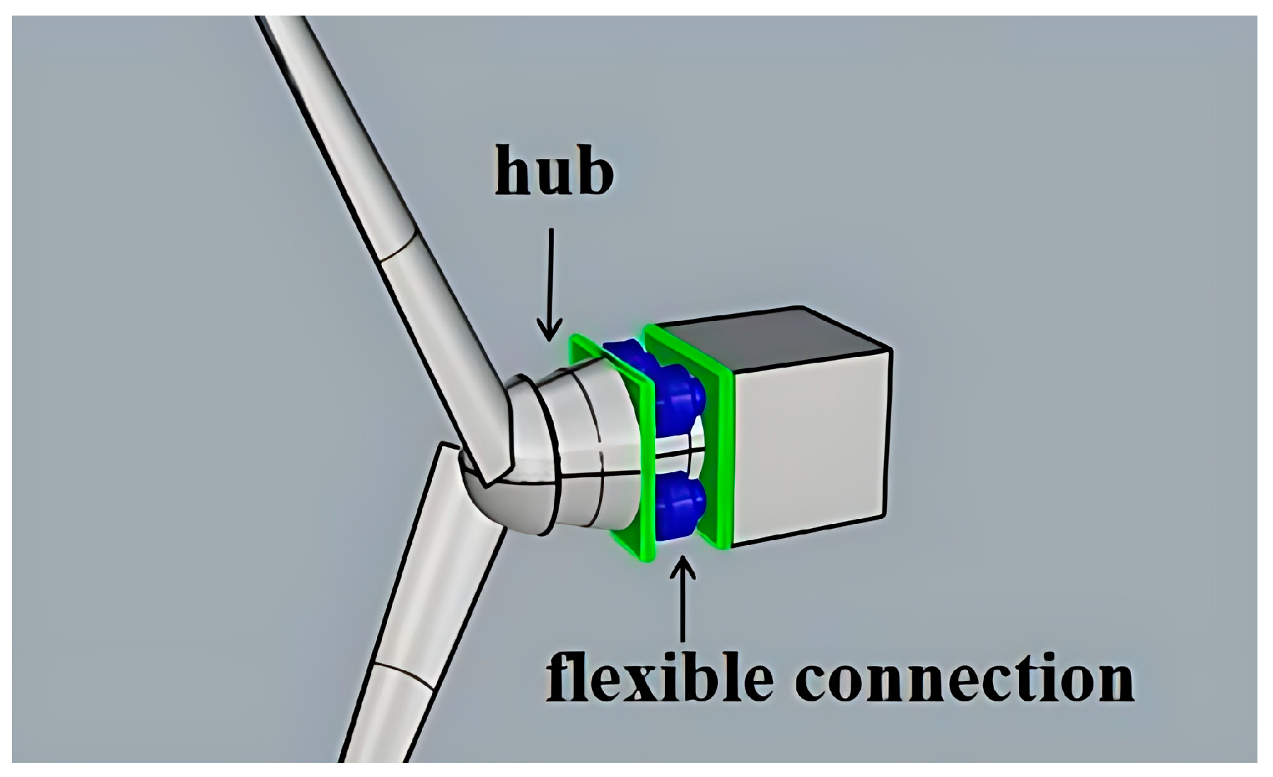
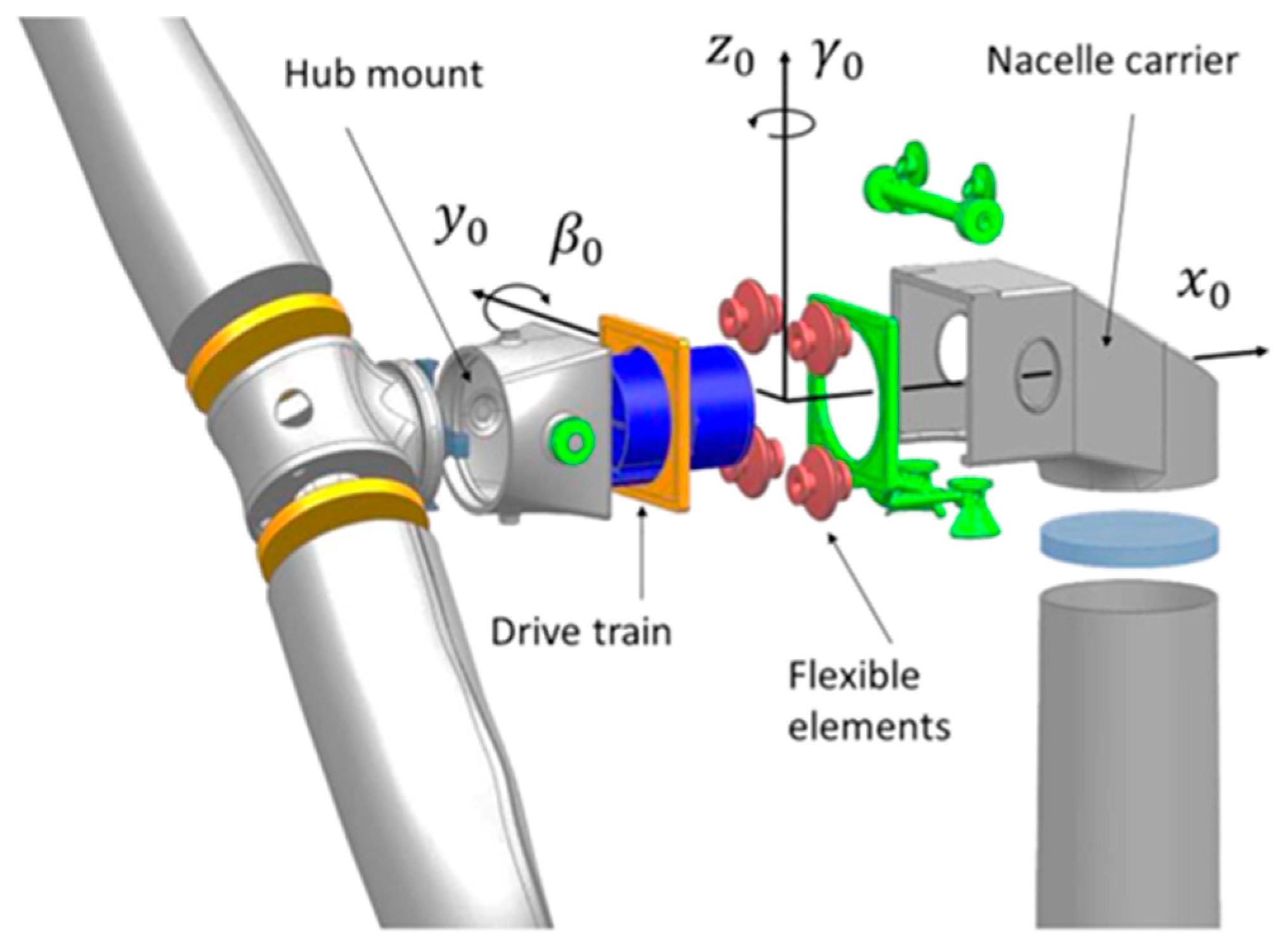
3.4. Flexible Hub Connection

In this paper, the flexible hub connection is introduced into a floating wind turbine by spring units that connect the hub with the nacelle (Figure 3). In SIMA, users can add spring elements and set the parameters of the response. It can simulate the small amplitude rotation motion of the rotor so there is extra multidirectional elasticity between the hub support and the engine room. The spring parameters of the turbine model are given in Table 3.

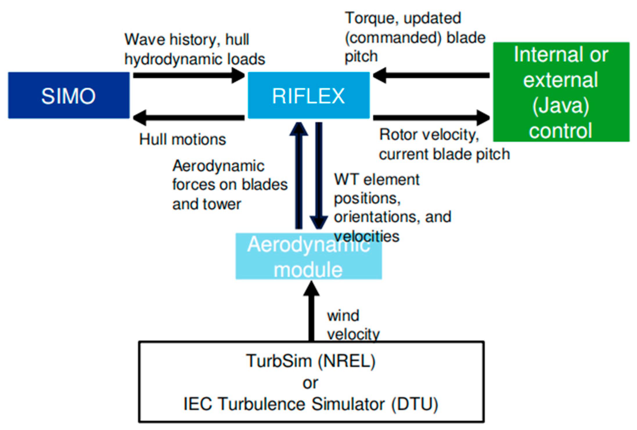
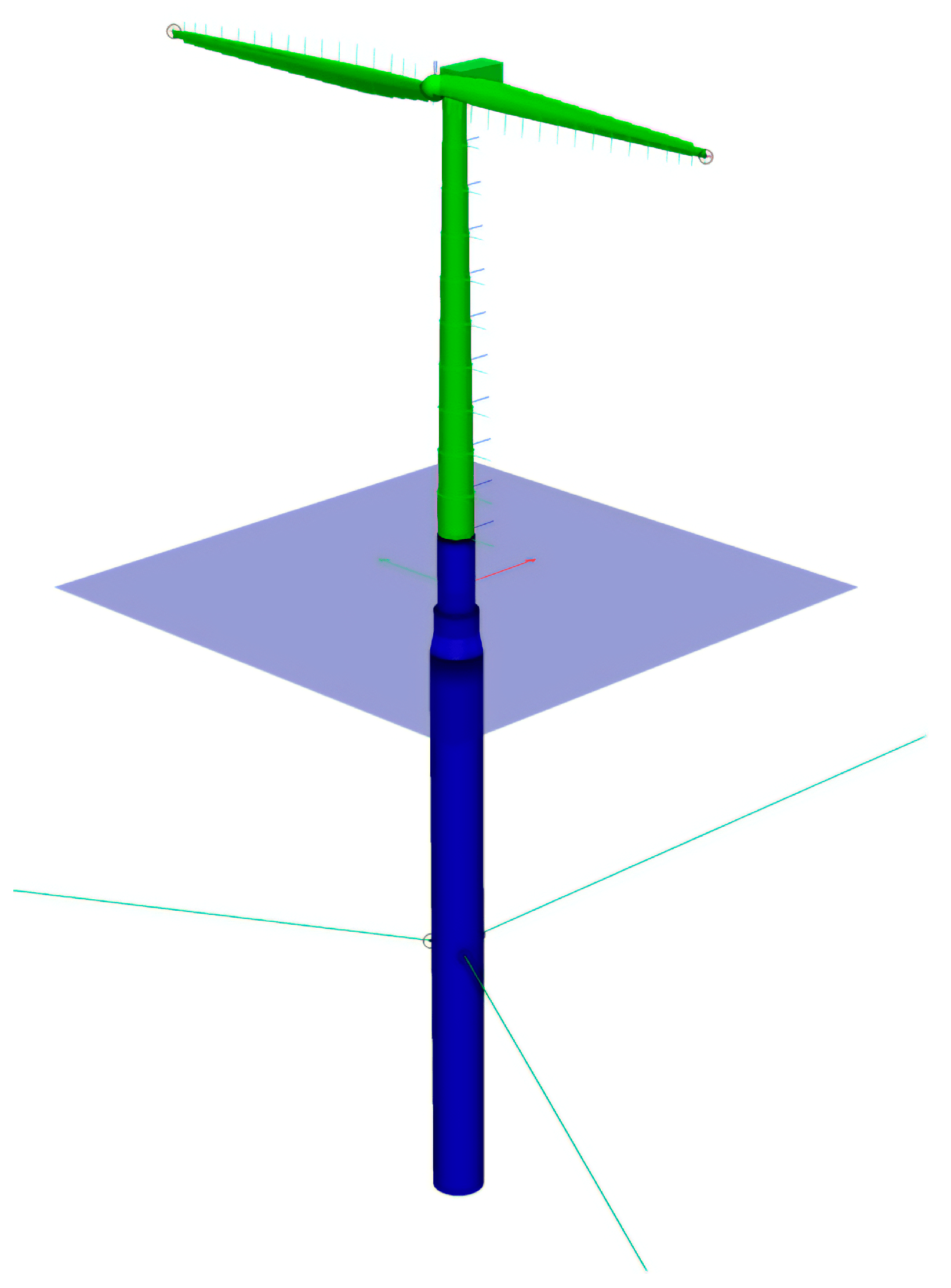
3.5. Fully Coupled Model

The 3D model of the platform was constructed in Rhino and its sat file form was exported to a panel model. HydroD (version 4.10) read the panel model and completed the hydrodynamic analysis. Then, the hydrodynamic calculation result file G1.SIF in the frequency domain is imported into SIMA (version 4.2) software of SESAM, and the coupled numerical model of the Spar-type floating two-blade flexible hub turbine is established. The coupling model of the Spar-type floating two-blade flexible hub turbine is shown in Figure 4; the blue part is the floating platform, and the green part above the floating platform represents the wind turbine.

3.6. Environment Load Cases

Eighteen load cases were applied for analysis. For each load case, irregular wave and stationary uniform wind were used. The JONSWAP spectrum is adopted for simulating the stochastic sea state, where Hs is significant wave height, Tp is the spectral peak period, and U is the mean wind speed. In this paper, it is assumed that the wind and waves are codirectional for all sea states to avoid a five-dimensional scatter diagram [47] choosing the direction of the x-axis as the excitation direction.
The time-step for the numerical integration was 0.005 s, and the calculation time lengths were 10,800 s for all cases. Details of the load cases are shown in Table 4.

4. Results and Discussion

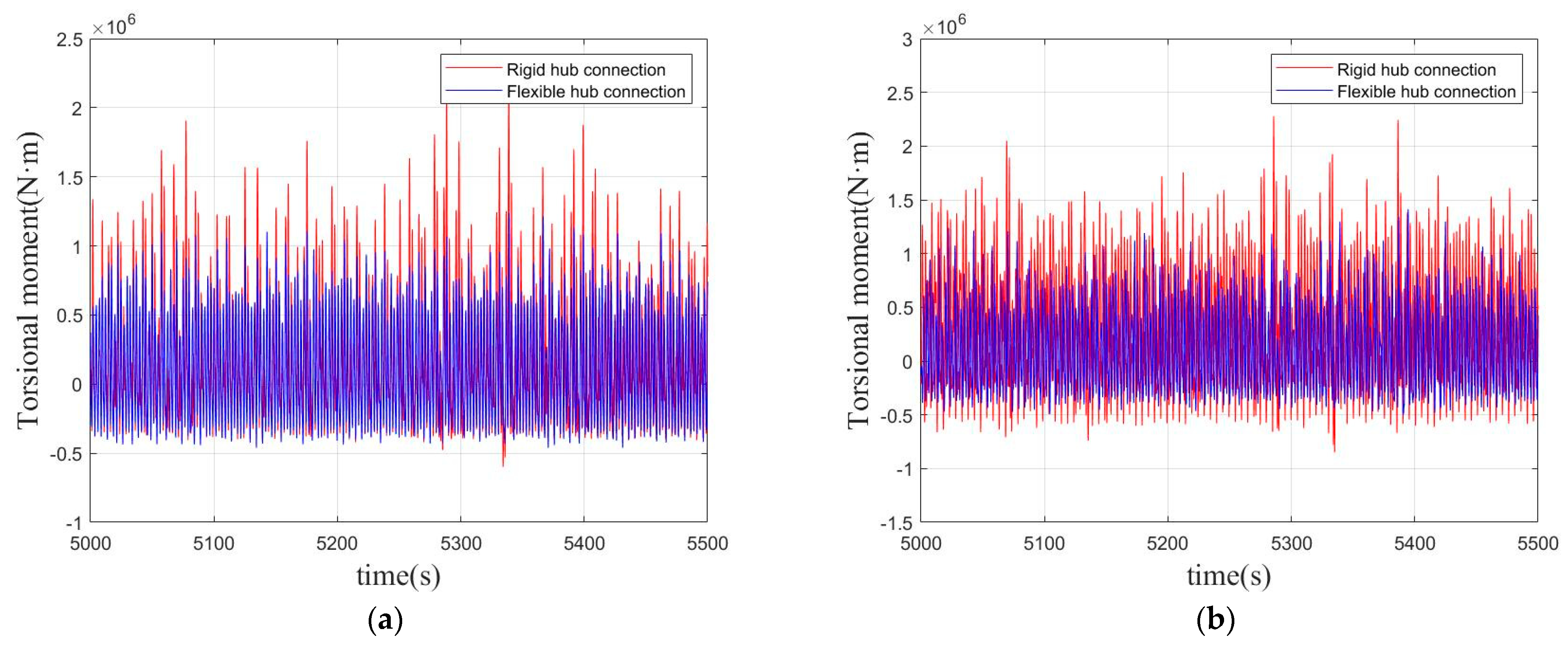
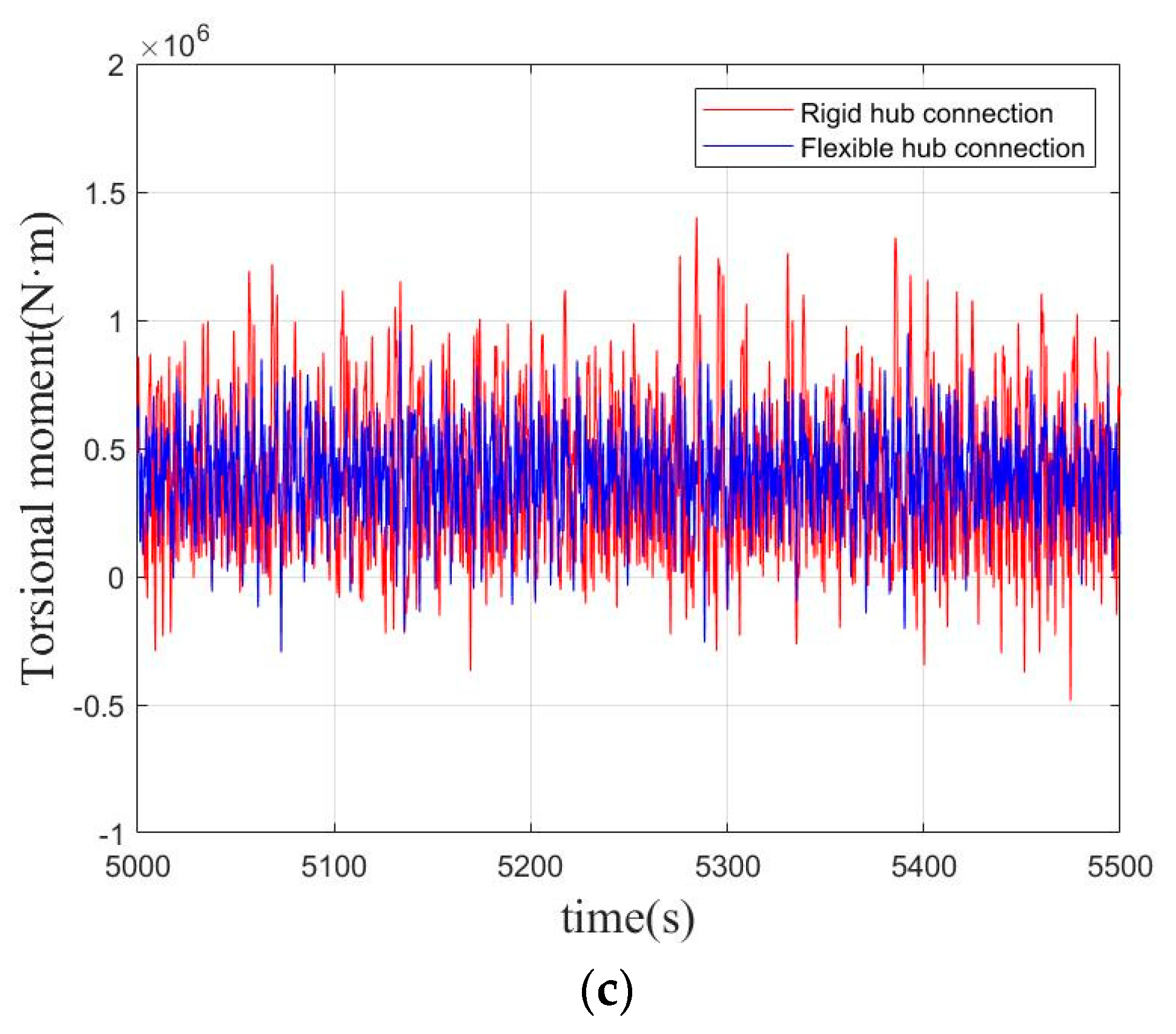
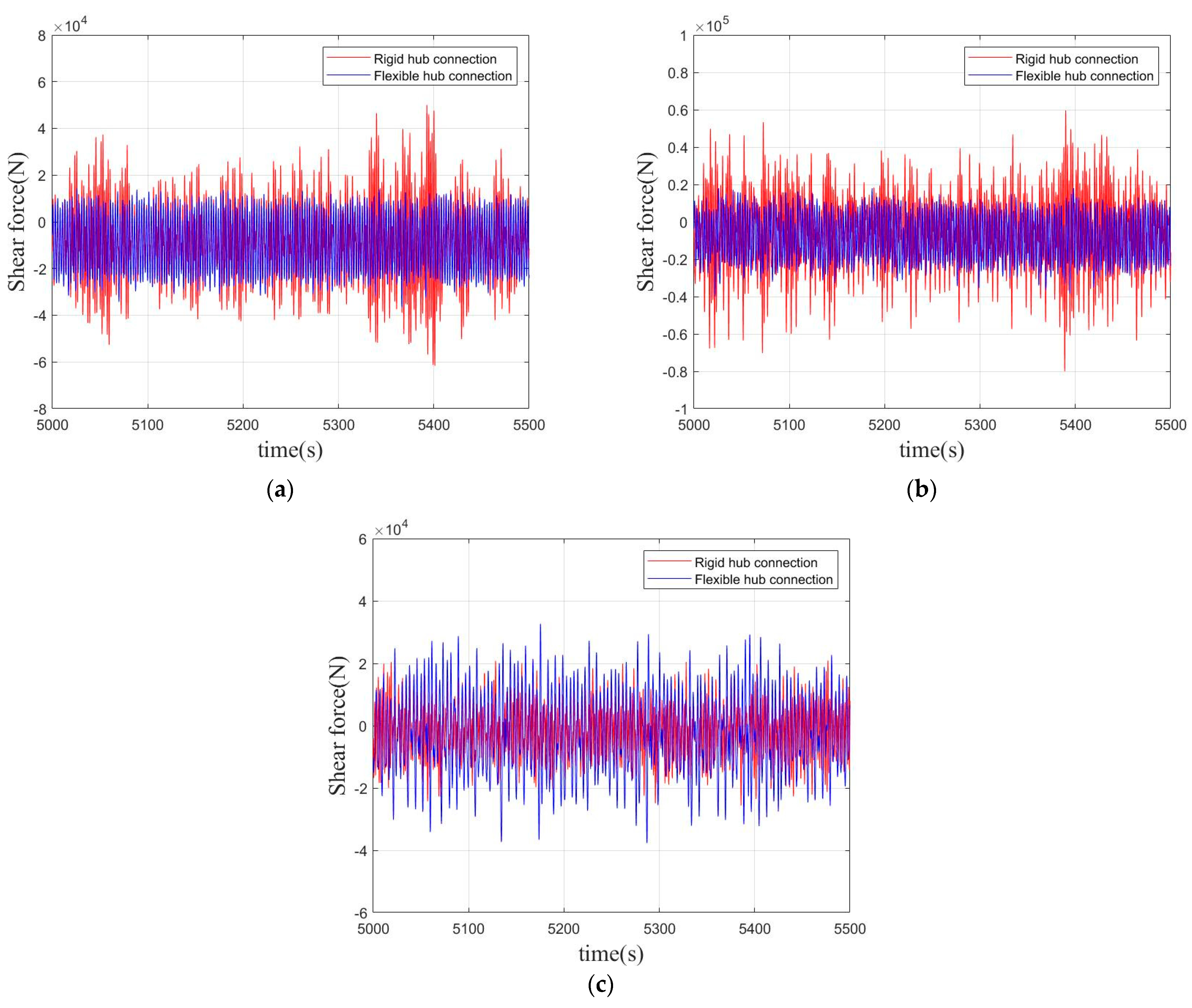
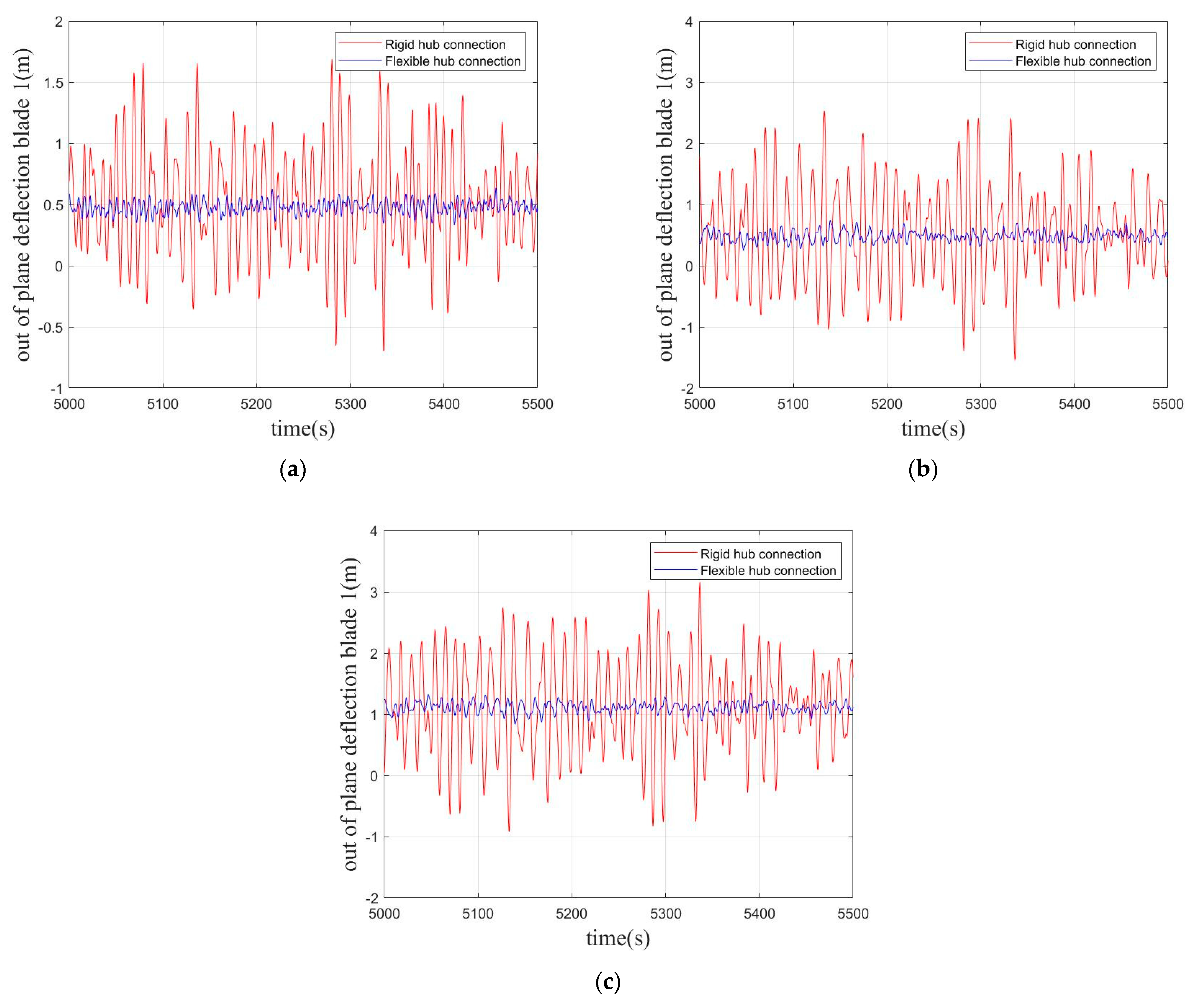
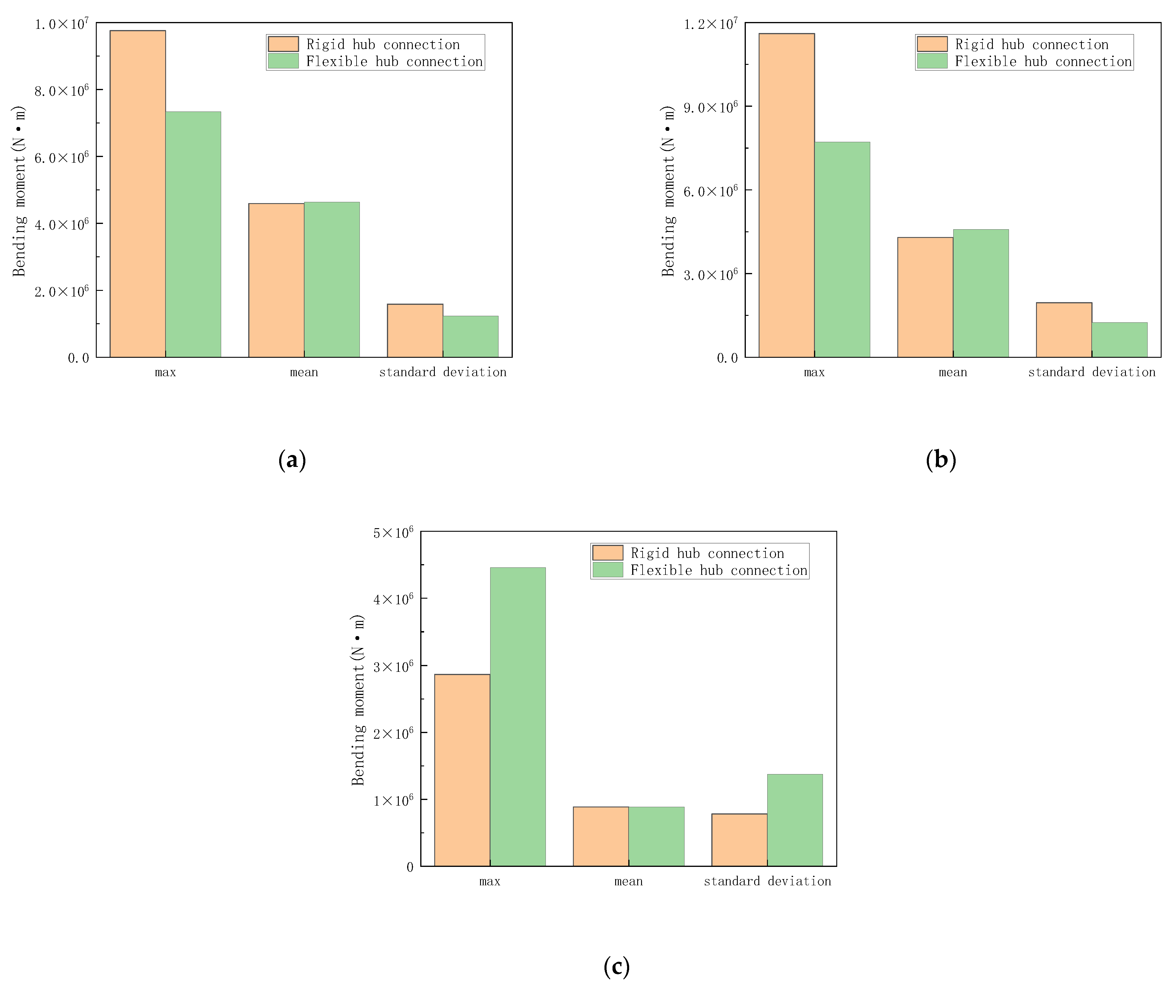
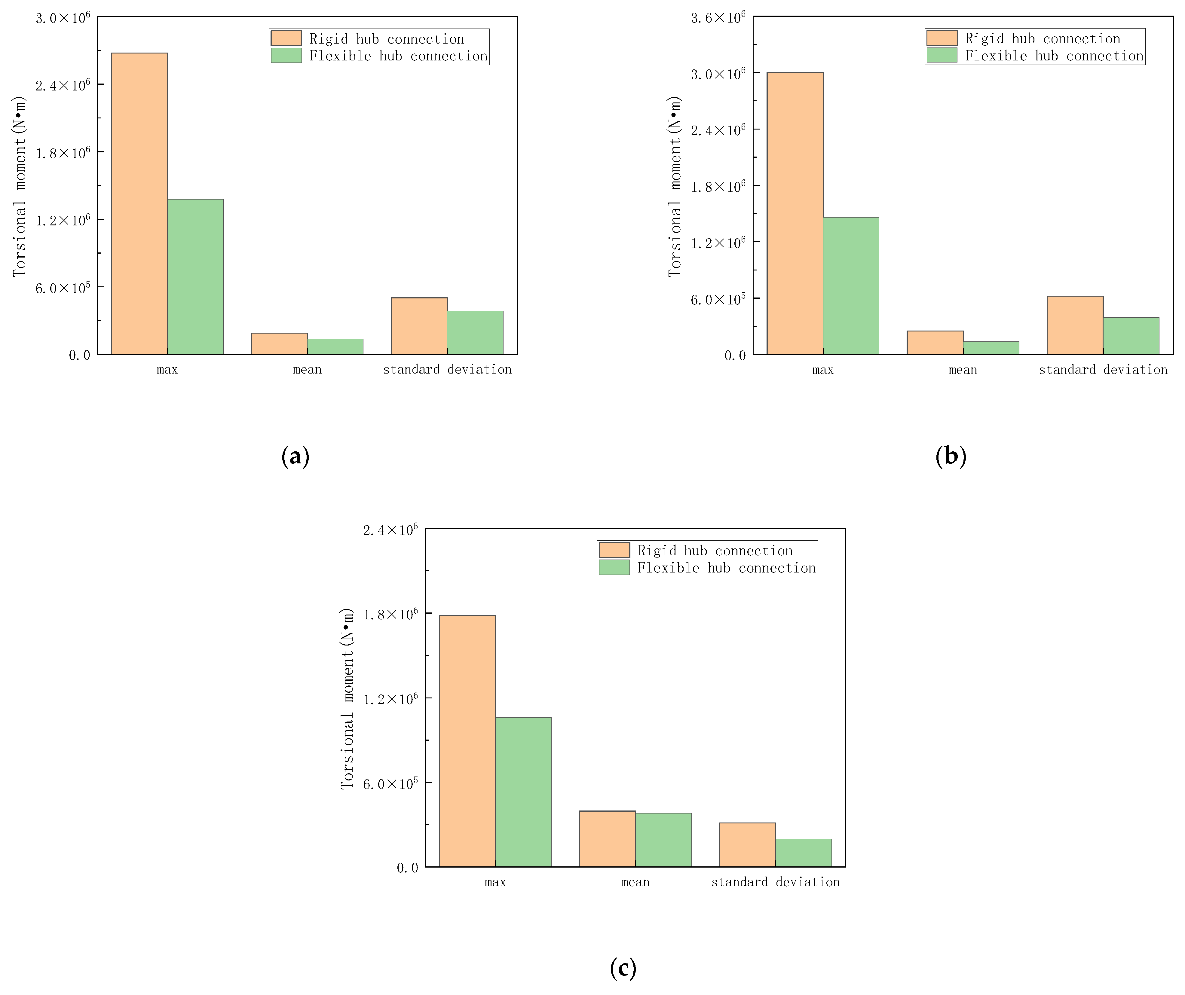
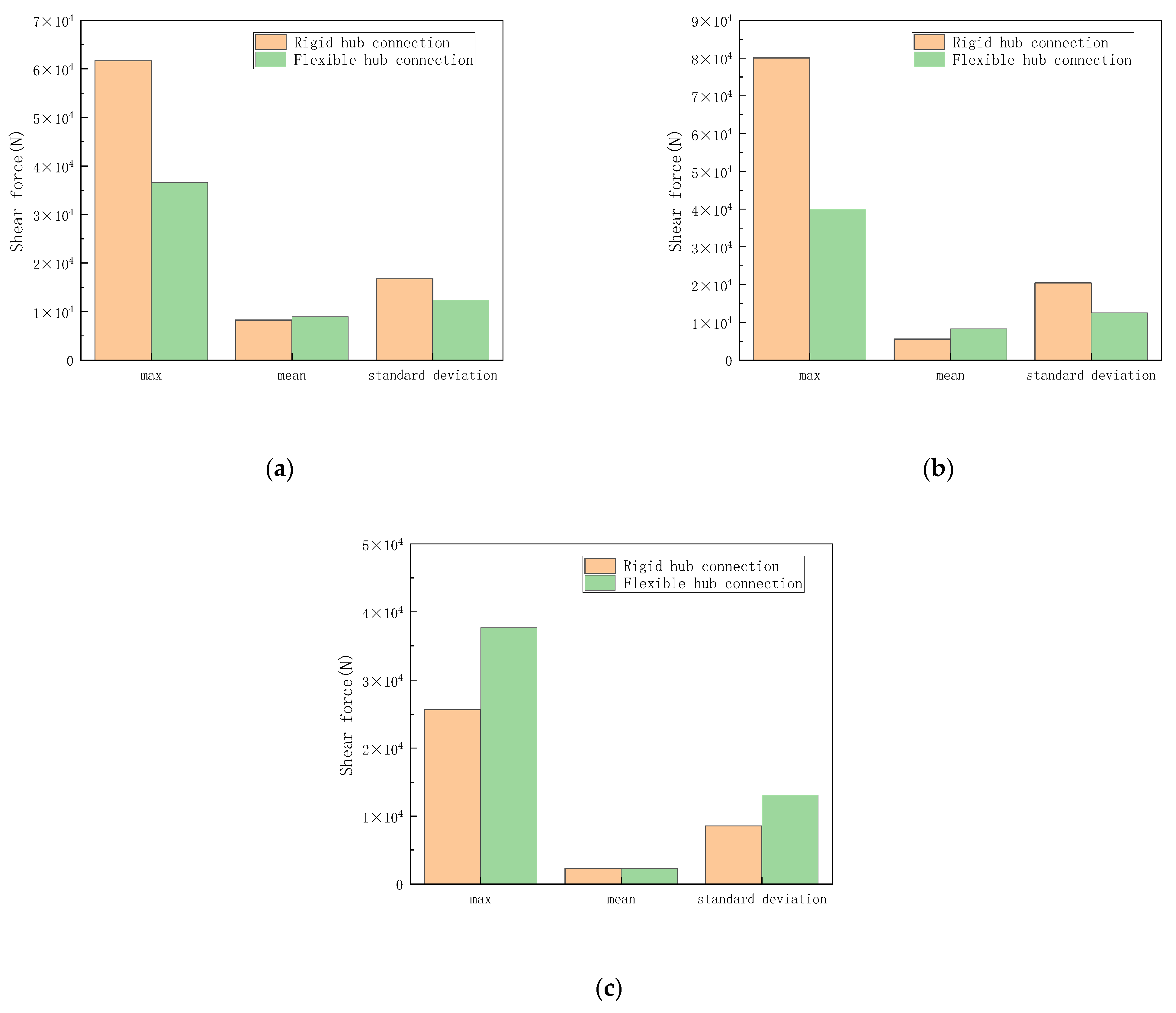
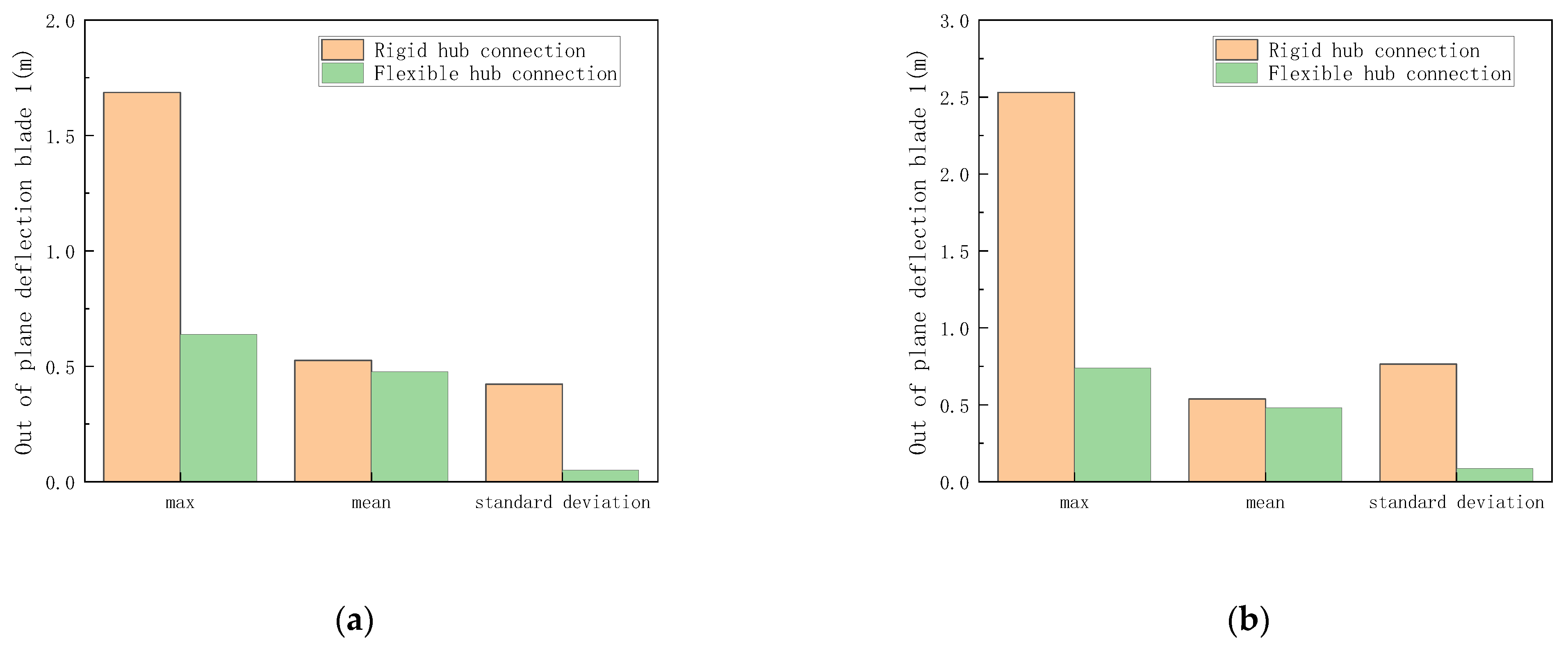
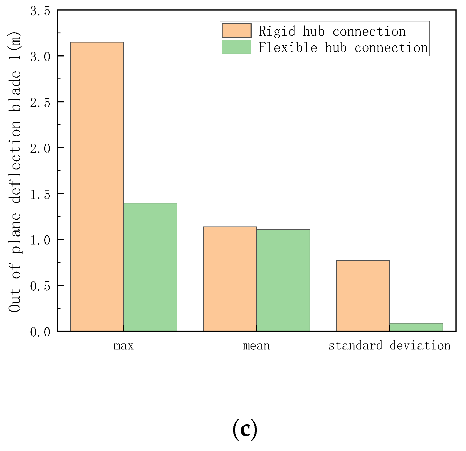
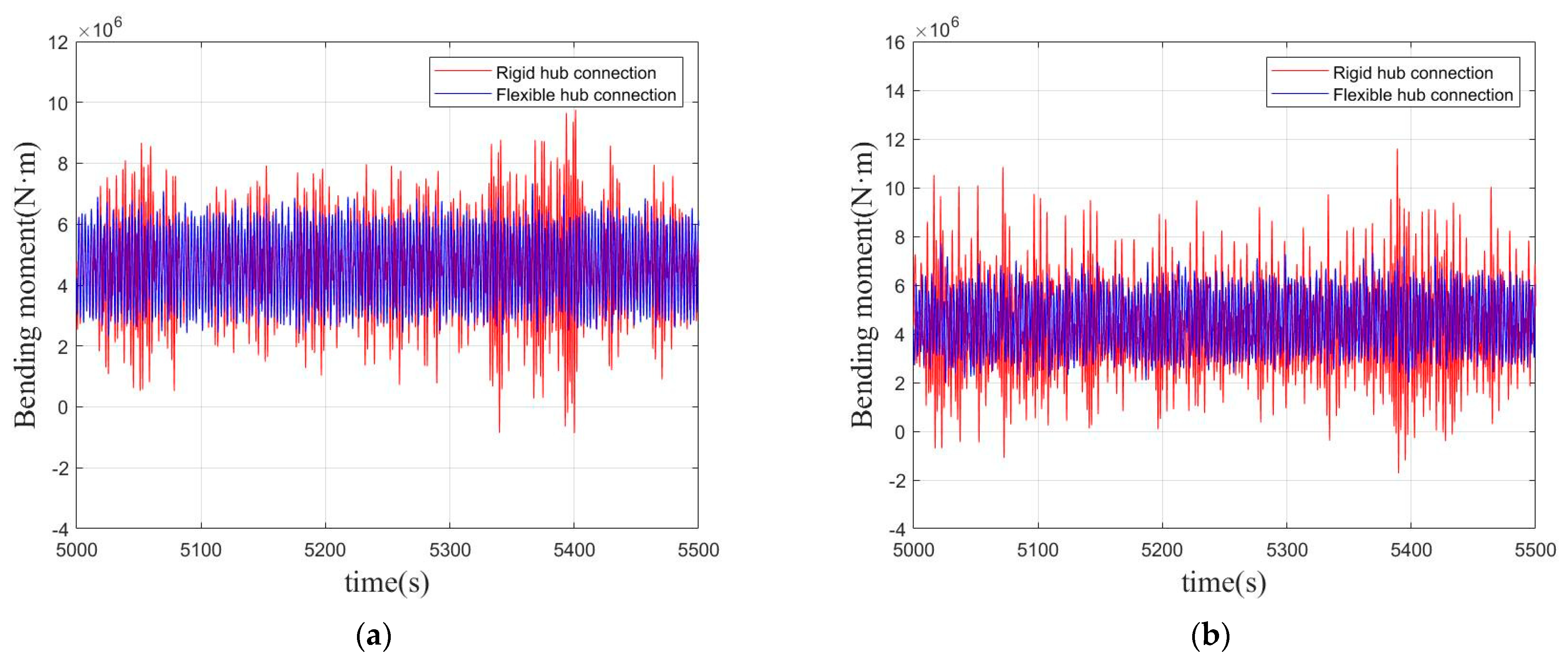
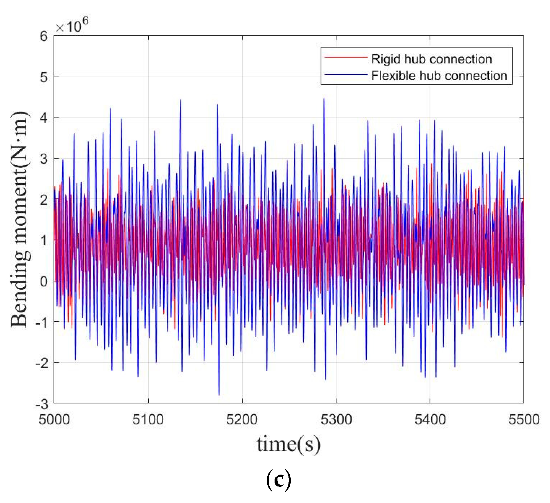
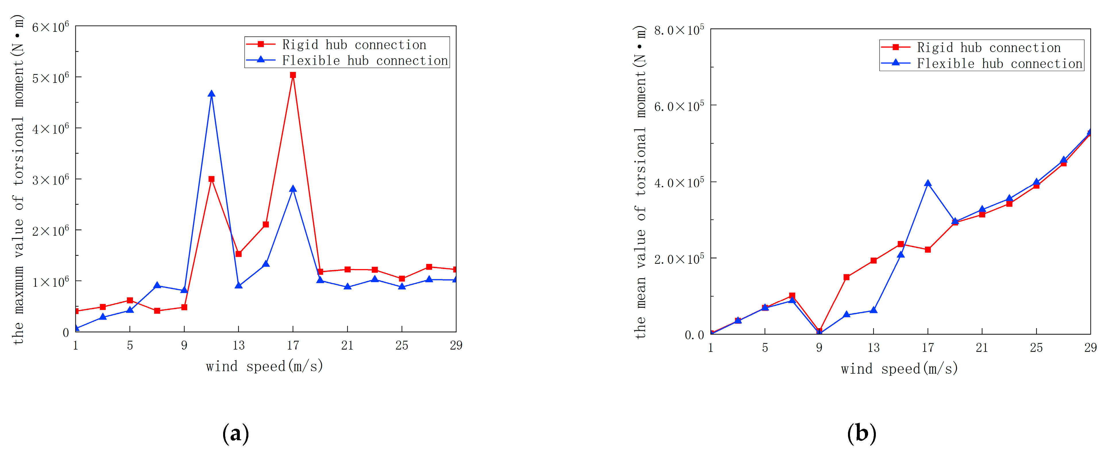
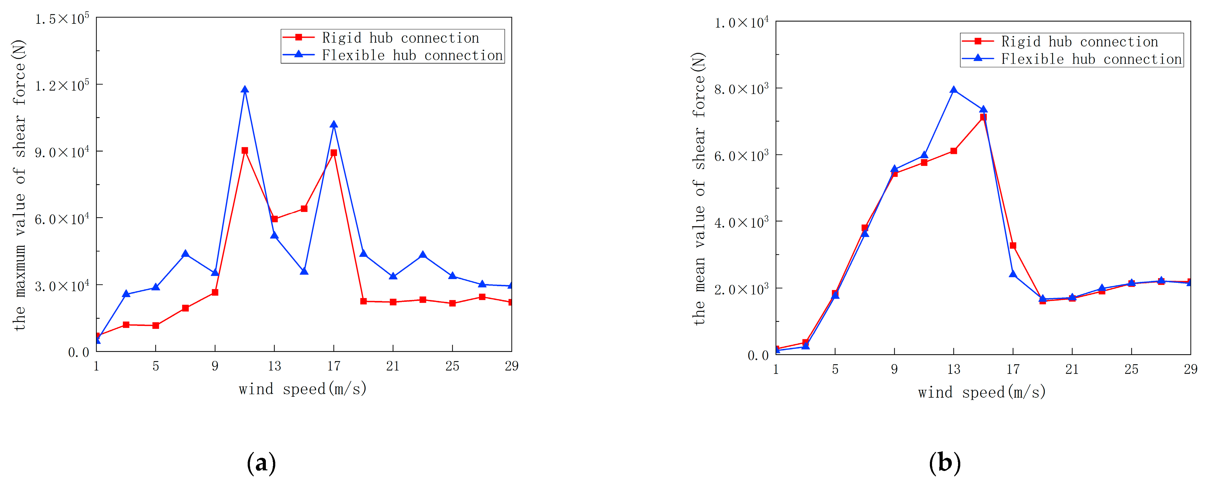
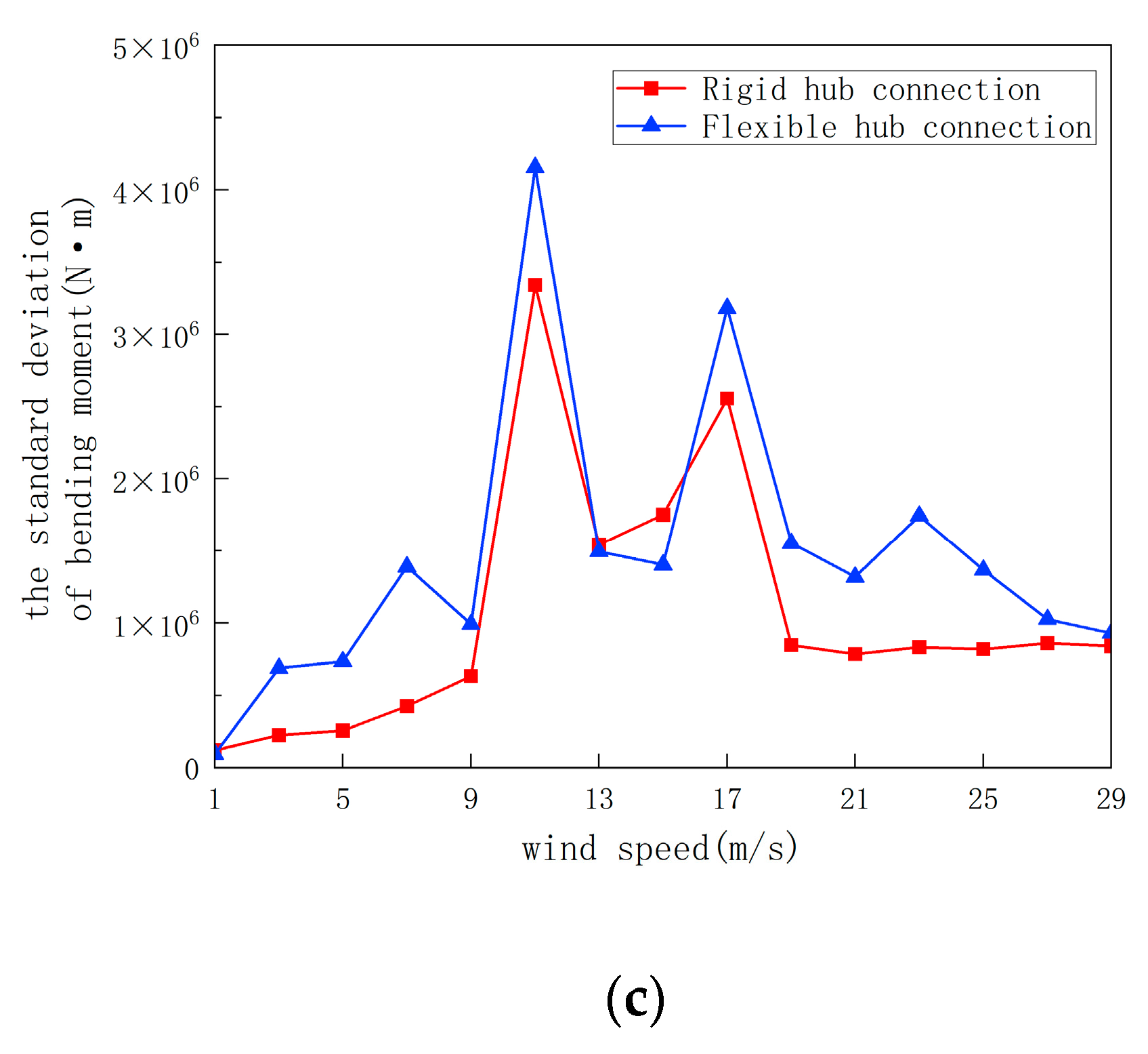
4.1. Analysis of Dynamic Structural Response

The time-series curves of the torsional moment of the tower and the shear force of the y-axis at the bottom of the tower are shown in Figure 5 and Figure 6. The load response statistics of the two types of wind turbines are compared in Figure 7 and Figure 8, respectively. The calculation time lengths are 10,800 s for the convenience of analysis, only the results of the 5000 s to 5500 s are selected for research.
As can be seen from Figure 5, compared with the Spar-type Offshore Floating Two-bladed Wind Turbine with the Rigid Hub Connection (OWTR), the Torsional moment of the tower of the Spar-type Offshore Floating Two-bladed Wind Turbine with Flexible Hub Connection (OWTF) is smaller and the time series curves are more concentrated. The specific statistical data are shown in Figure 6. It should be noted that the statistical data shown in Figure 6 are those after the wind turbines reached a steady state. It can be seen from Figure 6 that the maximum value, mean value and standard deviation of the tower of the OWTF are smaller than those of the OWTR. In LC1, the torsional load amplitude of OWTR is 2.68 × 10 6 N·m and the torsional load amplitude of OWTF is 1.38 × 10 6 N·m. In LC2 and LC3, the torsional load amplitudes of OWTR are 3.00 × 10 6 N·m and 1.78 × 10 6 N·m; the torsional load amplitudes of OWTR are 1.46 × 10 6 N·m and 1.06 × 10 6 N·m. The torsional load amplitudes are reduced by 48.6%, 51.4% and 40.5%, respectively, under three cases. This shows that by introducing the concept of flexible hub connection, the torsional load amplitudes of the two-blade wind turbine tower as well as the fatigue damage of the structure can be reduced.
Figure 7 shows the time series of shear forces in the y-axis direction at the bottom of the tower. Meanwhile, the statistical data of shear force are visually compared in Figure 8. It should be noted that the statistical data shown in Figure 8 are those after the wind turbines reached a steady state. In the process of wind turbine operation, the shear force of the OWTF is more concentrated than that of the OWTR, the amplitude, and the standard deviation are smaller, and the mean value is a little different. In case 1 and case 2, the shear force amplitudes of OWTR are 6.16 × 10 4 N and 8.00 × 10 4 N; the shear force amplitudes of OWTF are 3.66 × 10 4 N and 4.00 × 10 4 N which are reduced by 40.7% and 50.0%, respectively. This can reduce the structural damage during the operation of the two-blade turbines. Combining the equation of Section 2.2, after the flexible hub connection concept is introduced, the value of the restoring and resisting moments is increased. This results in a decrease in the amplitudes of the load transmitted to the tower. As described in Section 3.4, we introduce flexible hub connections in both y 0 and z 0 directions. That explains why the shear force of the y-axis at the bottom of the tower is reduced. It should be pointed out that y and y 0 are parallel. But in case 3, the introduction of a flexible hub connection increases the amplitude of shear force, and the shear force of OWTR is 32% lower than that of OWTF, the average shear force of OWTR and OWTF is 2.56 × 10 4 N and 3.77 × 10 4 N. The effects of shear forces at different wind speeds will be shown in Section 4.2.
The structural loads on blade 1 are characterized by the out-of-plane blade deflection in Figure 9. When the two-blade turbines are working, the out-of-plane blade deviation will be generated, which may cause damage to the blade. This situation can be effectively improved by introducing the concept of flexible hub connection. It can be seen from Figure 9 that OWTF’s out-of-plane blade deflection time series is more concentrated than OWTR’s, with a smaller amplitude and slightly smaller average value, which is also confirmed in the statistical data comparison chart in Figure 10. In three cases, the out-of-plane blade deflection amplitude of OWTR is 1.70 m, 2.51 m and 3.17 m, respectively, and the out-of-plane blade deflection amplitude of OWTF is 0.64 m, 0.73 m, and 1.40 m, respectively. The out-of-plane blade deflection amplitudes are reduced by 62.2%, 70.8% and 55.7%, respectively, under three cases. This shows that the introduction of the concept of flexible hub connection can reduce the load response of wind turbine blades, and the damage of wind turbine blades, and play a protective role.
The time series of the bending moment at the bottom of the tower in the z-axis direction is shown in Figure 11, and the maximum value, mean value and standard deviation are shown in Figure 12. In the pictures, simulation data ranging from 5000 s to 5500 s are selected for display. It can be seen that the amplitude of the bending moment at the bottom of the OWTR tower is larger than that of the OWTF under rated wind speed, which is beneficial for extending the service life of the wind turbine. In case 1 and case 2, the mean value of the bending moment of OWTR and OWTF is almost the same, but the maximum value of the bending moment of OWTF is 24.8% and 33.5% lower than that of OWTR, respectively. In case 1 and case 2, the maximum value of the bending moment of OWTR is 9.76 × 10 6 N·m and 1.16 × 10 7 N·m, respectively; the maximum value of the bending moment of OWTF is 7.34 × 10 6 N·m and 7.71 × 10 6 N·m, respectively. The introduction of flexible hub connections helps to protect the tower of the wind turbine. Under extreme wind load conditions, the average bending moment exhibited by the two connection types demonstrates subtle disparity; the maximum bending moment of OWTF is larger than that of OWTR, which puts forward a test for the design of the section of the tower and the material stiffness of the tower. In case 3, the maximum bending moment of OWTR and OWTF is 2.87 × 10 6 N·m and 4.46 × 10 6 N·m, respectively; the maximum bending moment of OWTR is 35.7% higher than that of OWTF, and the introduction of the flexible hub connection increases the bending moment of the tower. The effects of bending moments at different wind speeds will be shown in Section 4.2.

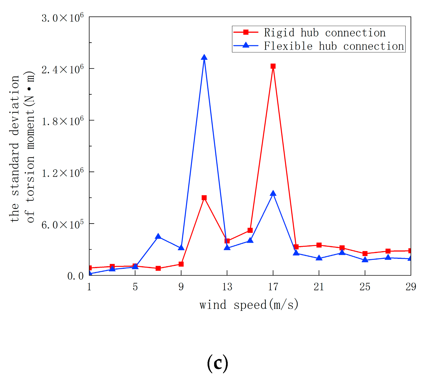
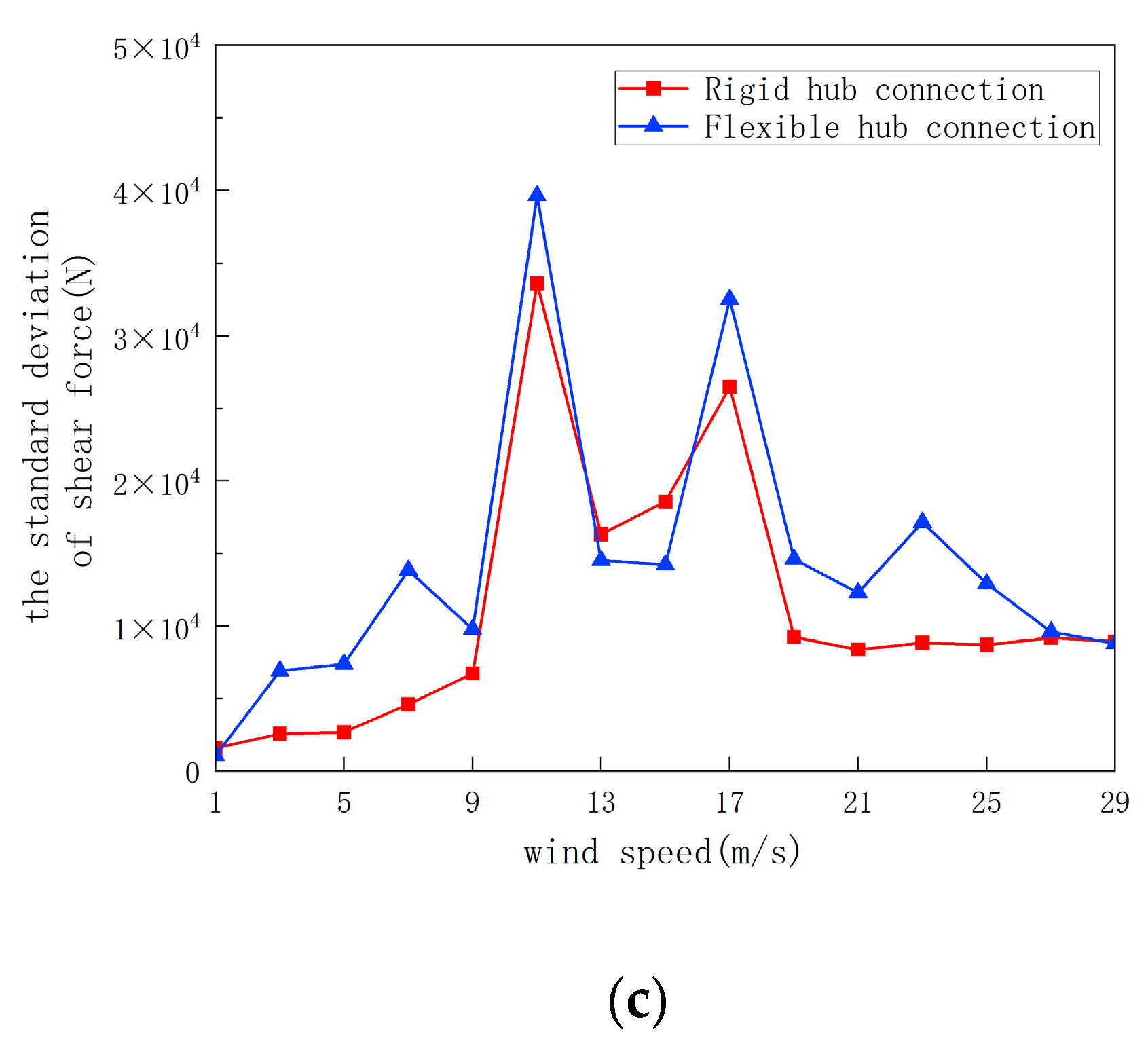
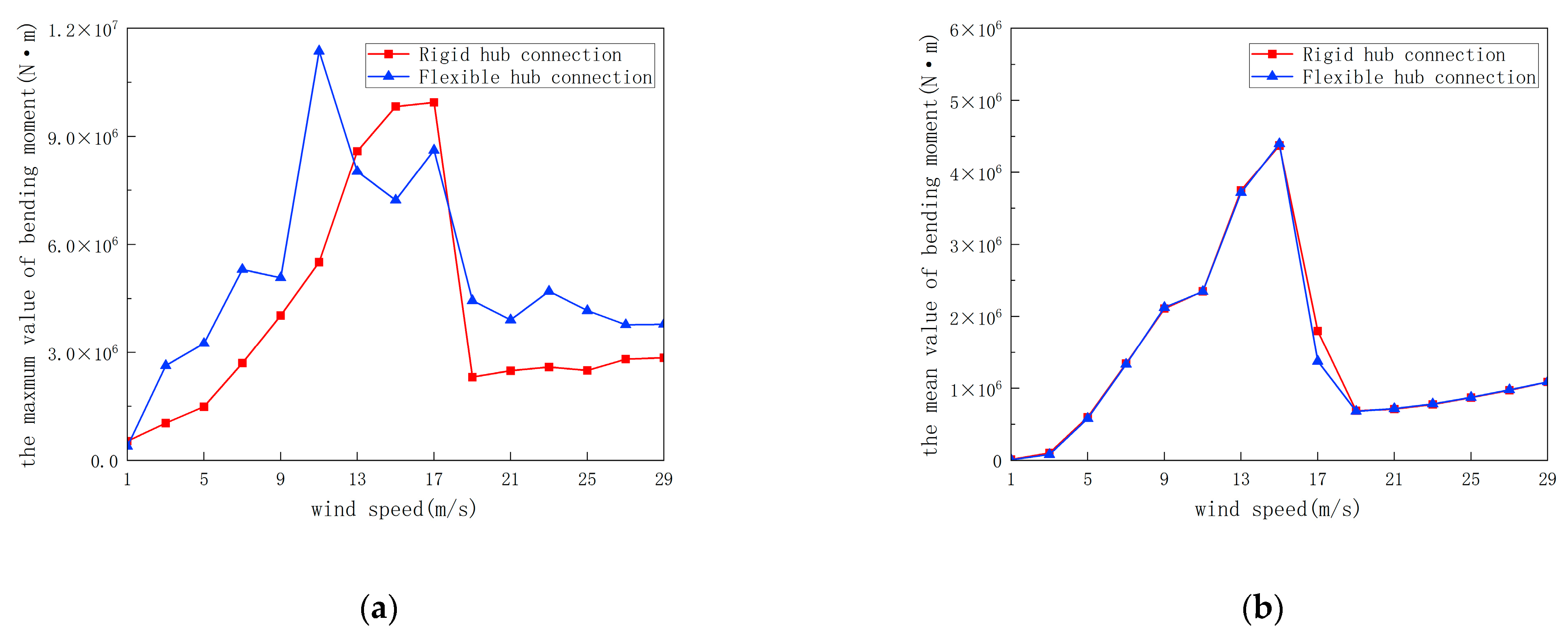
4.2. Sensitivity Analysis of Wind Speed on Tower Responses

In Section 4.1 we show the load response at wind speeds of 15.7 m/s and 25 m/s. In order to further explore the load response of the two-blade wind turbine to the introduction of the concept of flexible hub connection, the OWTR and OWTF models were, respectively, established to operate under wind speed conditions ranging from 1 m/s to 29 m/s, one working condition was taken every 2 m/s interval; the significant wave height was 3.66 m, and the spectral peak period was 9.7 s. The time series of the load response curves of some working conditions are shown in Section 4.1. All the statistical data were collected after the wind turbine operation reached a steady state.
Figure 13 shows the statistical data of the torsional moment of the tower. Figure 13b shows the mean value of the torsional moment. It is found that under a wind speed of 9 m/s–17m/s, the torsional moment of OWTR and OWTF is somewhat deviated. Figure 13a is the maximum value of torsional moment and Figure 13c is the standard deviation of torsional moment. It can be seen that after reaching the steady state, the two curves show a similar trend. Under the conditions of 11 m/s and 17 m/s wind speed, the maximum value and standard deviation of the two models have a sudden increase. This may be related to the natural frequency of the hub connection model. It can be concluded from Figure 13 that under the working condition of 7 m/s–17 m/s, the introduction of a flexible hub connection will increase the torsional moment of the tower of the two-blade wind turbine. In the rest of the working conditions, the introduction of a flexible hub connection will reduce the impact of the torsional moment of the tower, and play a protective role.
Figure 14 shows the statistical data of shear force in the y-axis of the tower under different wind speeds. Figure 14b shows the mean value of shear force. The curve tends to increase first and then decrease, reaching the maximum at about 13 m/s wind speed. After the introduction of the flexible hub connection, the mean value is in good agreement except for a certain deviation under the working condition of 12 m/s–16 m/s. It can be seen from Figure 14a and Figure 13c that under the working condition of 12 m/s–16 m/s, the maximum value and standard deviation of the shear force of OWTF are smaller than that of OWTR. This is beneficial for protecting the wind turbine. However, the maximum value and standard deviation of the shear force of OWTF are larger than that of OWTR under other wind speed conditions. The maximum deviation of the maximum value can reach 55.3%, and the maximum deviation of the standard deviation can reach 66.8%.
Figure 15 shows the statistical data of the tower on the z-axis. Figure 15b is the statistical data of the mean value, and it can be seen that the two curves match very well. The curve tends to increase first and then decrease, reaching the maximum at about 14 m/s wind speed. Figure 15a is the statistical data of the maximum value. It can be seen that under the working condition of 12 m/s–18 m/s wind speed, the maximum value of OWTF is smaller than that of OWTR, and the standard deviation of OWTF is smaller than that of OWTR under the working condition of 12 m/s–16 m/s wind speed, which indicates that the introduction of the concept of flexible hub connection reduces the influence of the bending moment. However, in the remaining working conditions, the introduction of the concept of flexible hub connection will aggravate the impact of bending moments. The maximum deviation of the maximum value reached 52.6%, and the maximum deviation of the standard deviation reached 20.0%.

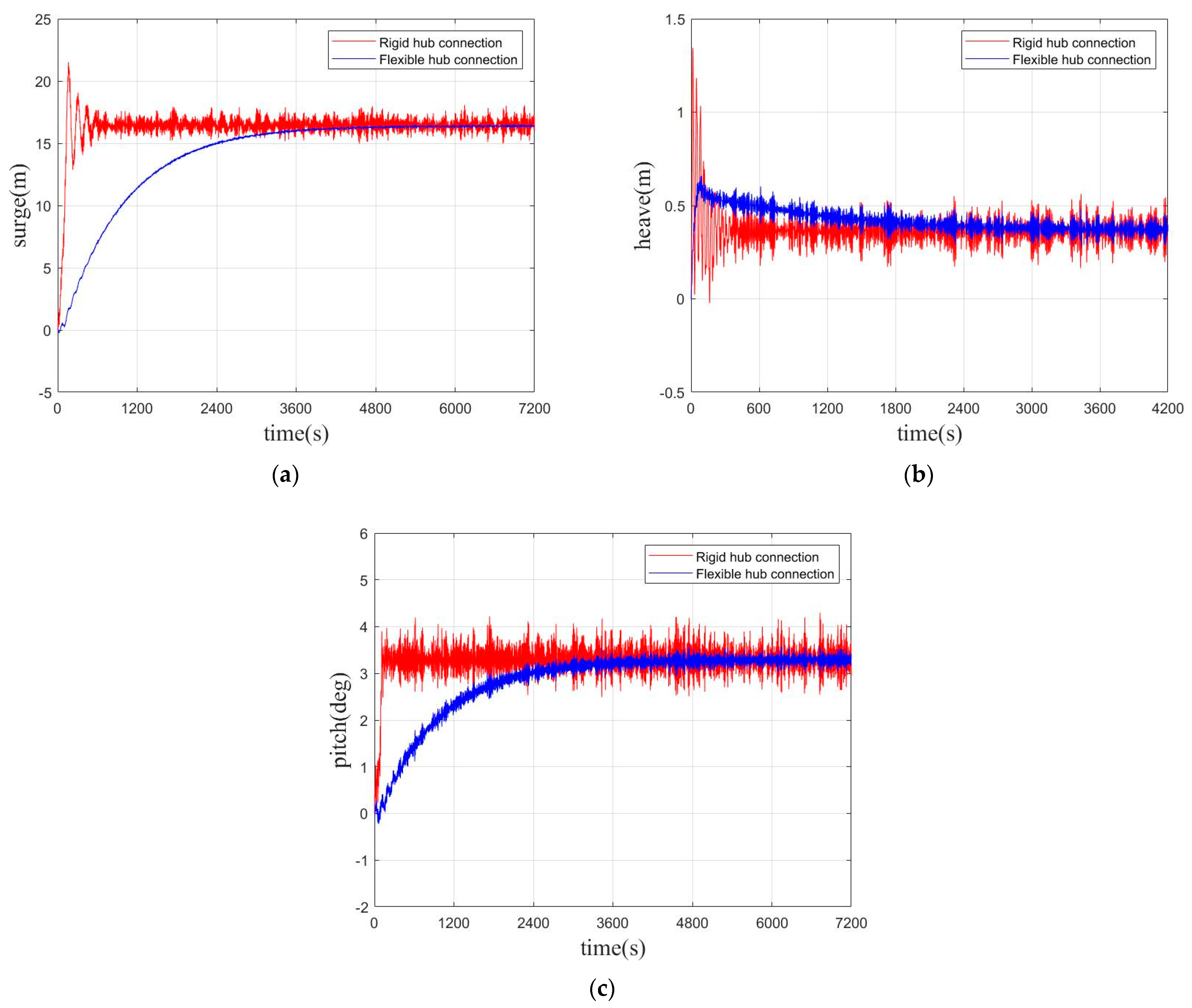
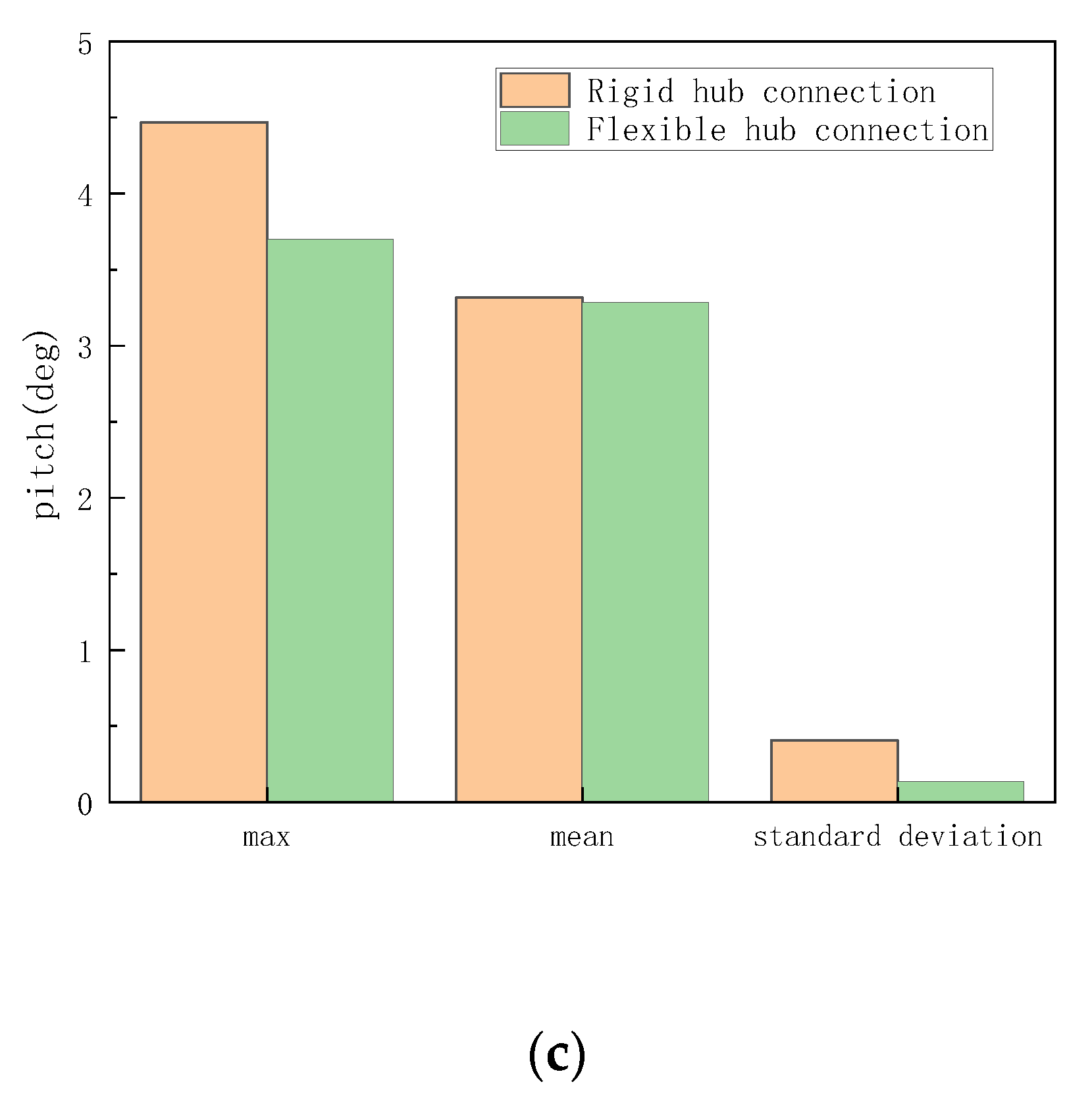
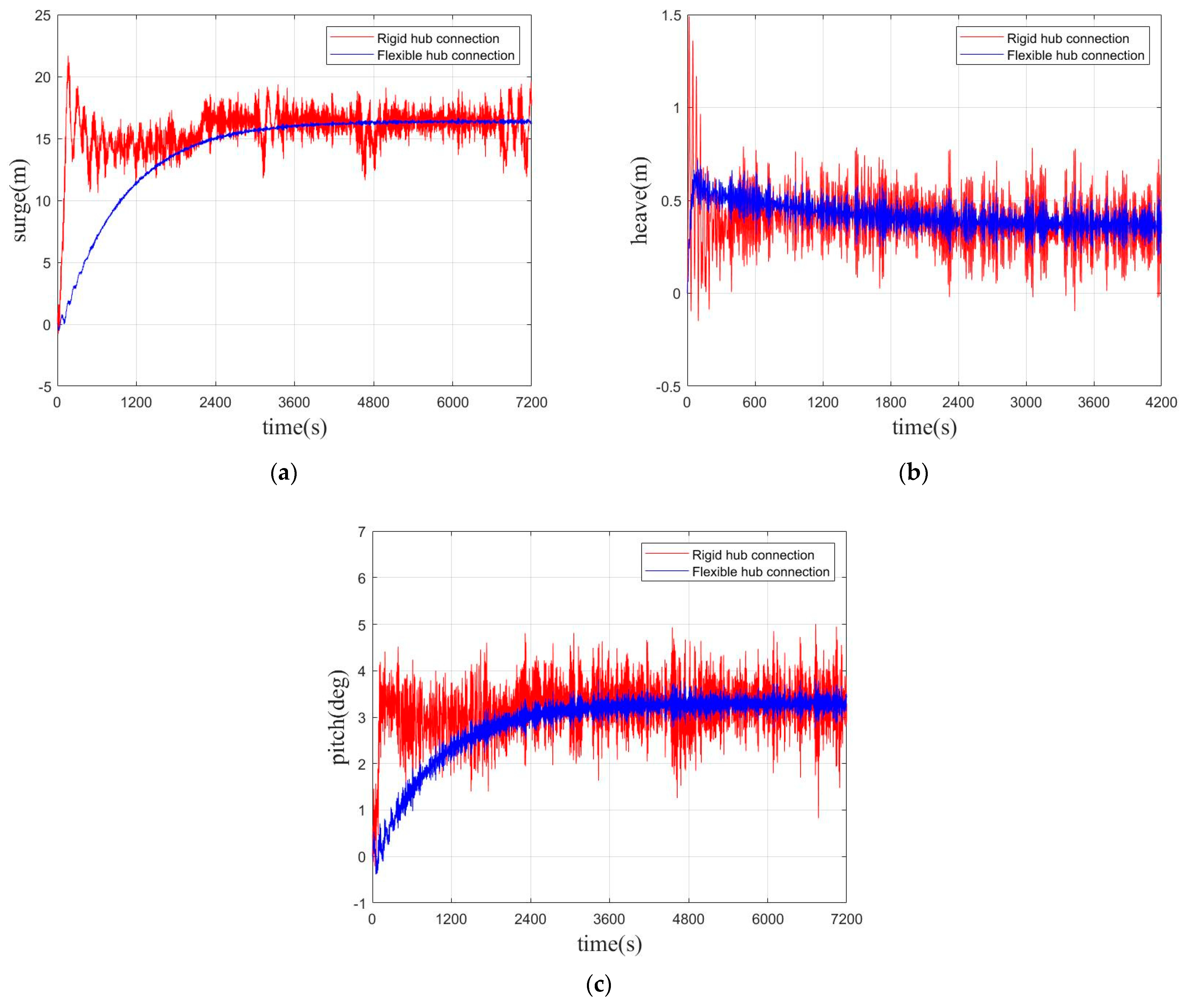
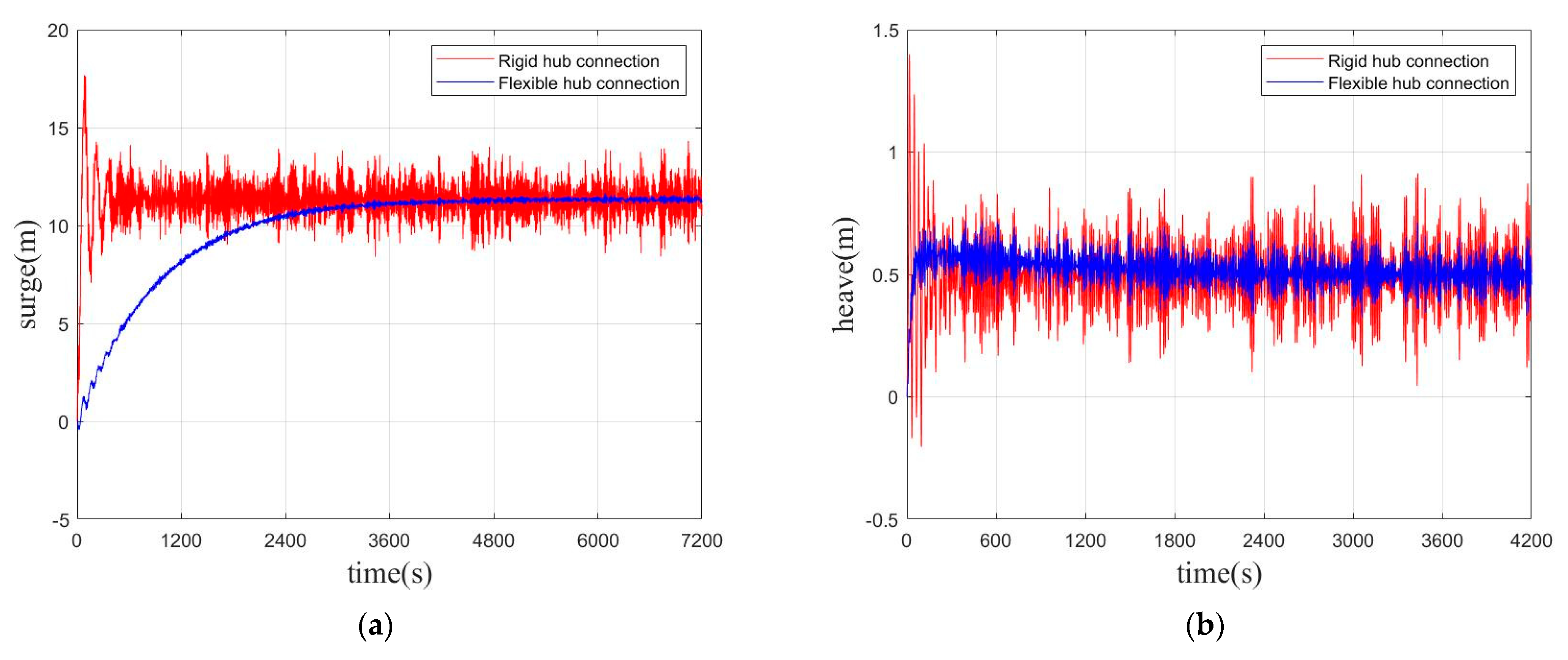
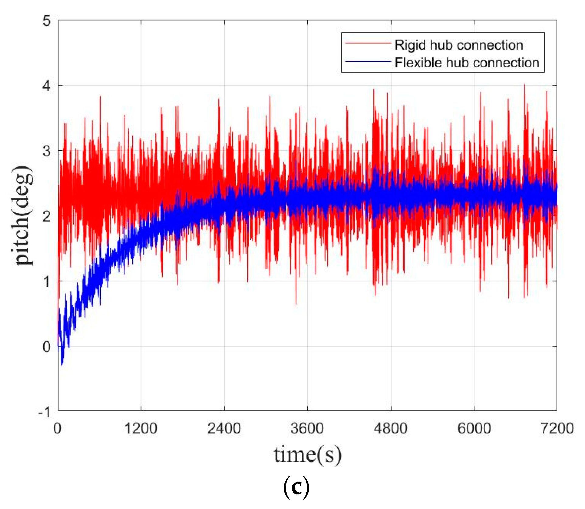
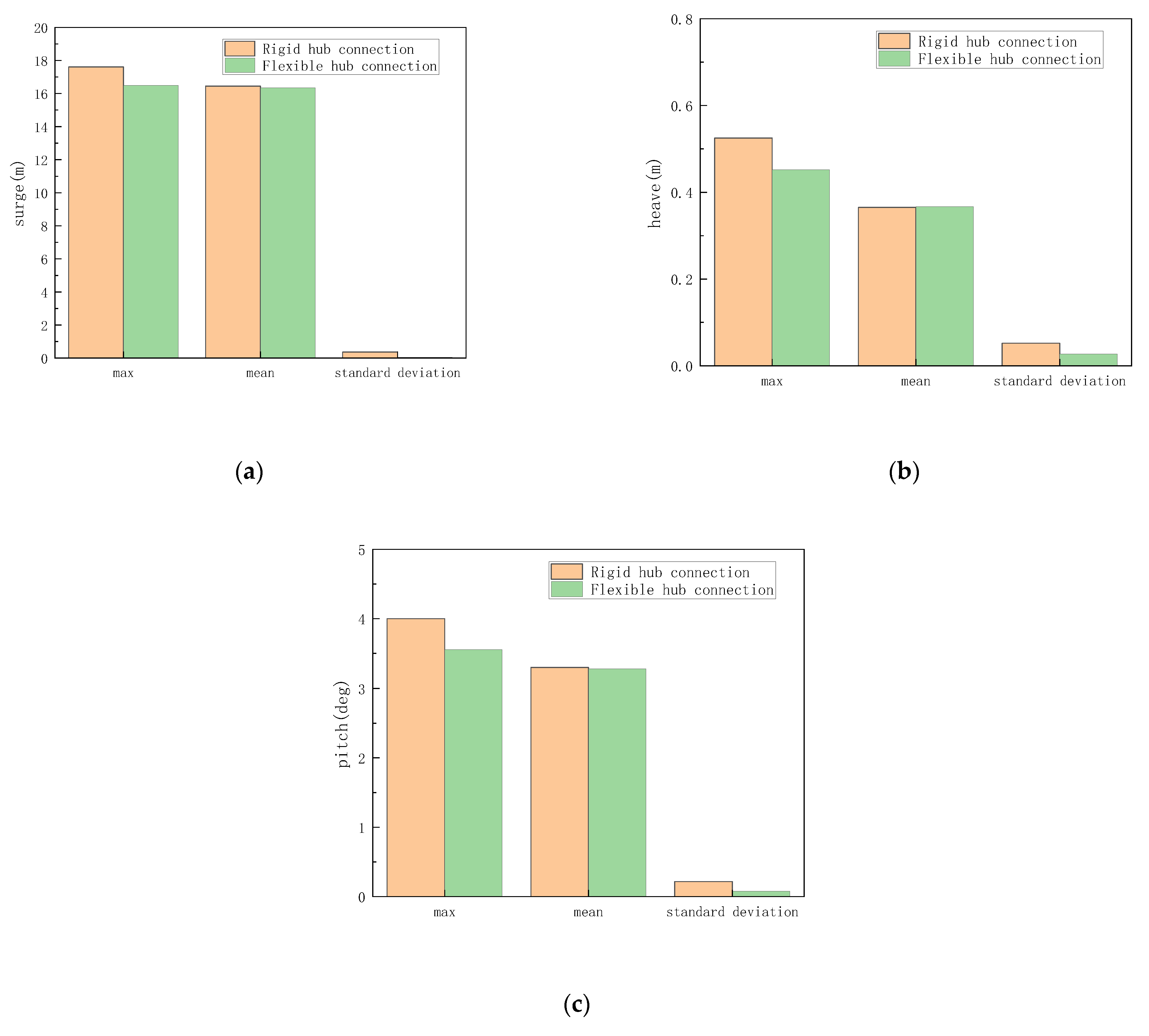
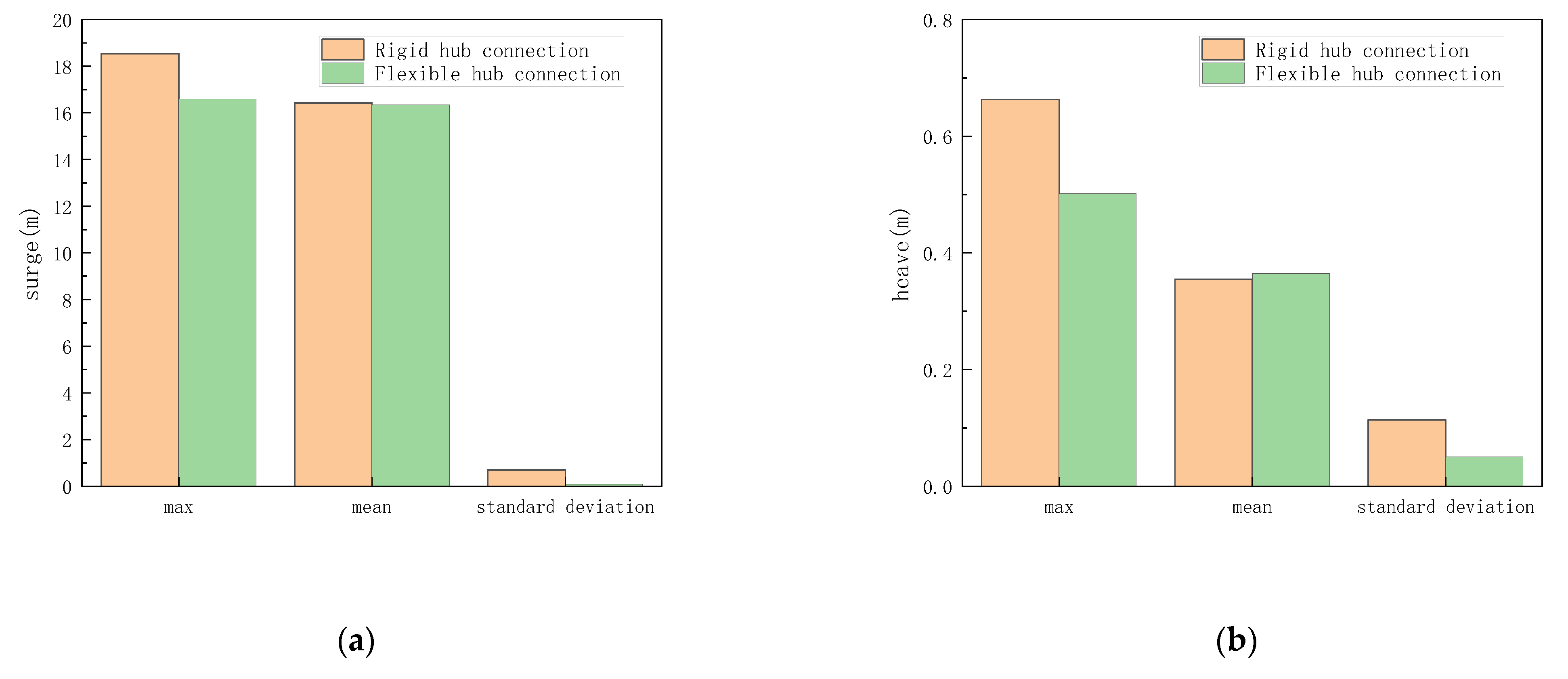
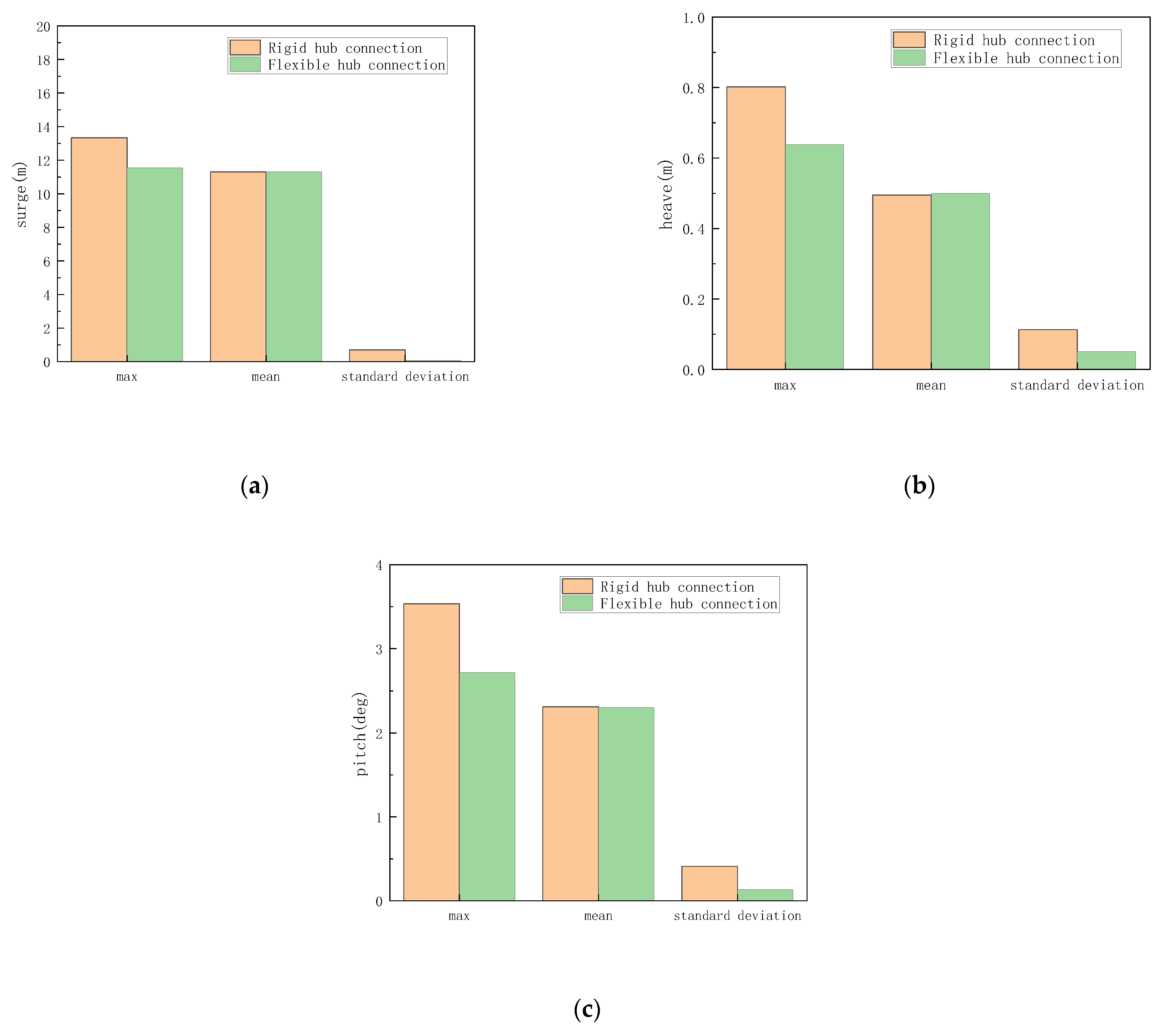
4.3. Dynamic Response Analysis of the Floater Motion

The time-domain motion responses of the Spar-type floating two-blade flexible hub turbine in surge, heave, and pitch degrees of freedom were calculated by applying irregular waves and stationary uniform wind to the system. These responses were then compared with the responses of the Spar-type floating two-blade turbine.
To facilitate a better comparison, rated wind speed and extreme wind speed were considered separately. The calculation was performed over a time span of 10,800 s. For the sake of analysis, only the results from 0 s to 7200 s in the surge and pitch directions as well as the results from 0 s to 4200 s in the heave direction are presented. Results are shown in Figure 16, Figure 17 and Figure 18.
The time-domain motion responses of the floater in the rated wind speed are shown in Figure 16 and Figure 17. The wind speed in the two cases was the rated wind speed of the wind turbine at 15.6 m/s. In these two cases, different significant wave heights and spectral peak periods were set, and it can be seen that the time-domain motion of the spar platform presents the same trend. The surge of the OWTR will stabilize in about 1000 s, while that of the OWTF will stabilize in about 4800 s. Before stabilizing, the surge value of the OWTF shows a parabolic upward trend and eventually reaches the same average surge value as that of the OWTR. In the whole process, the amplitude of surge oscillation of the OWTF is much smaller than that of the OWTR. The heave of the spar-type floating two-blade turbine will stabilize in about 300 s, while that of the OWTF will stabilize in about 3000 s. Before the stability, OWTR will have a larger heave value due to the instantaneous effect, and then quickly stabilize. However, the mean value of the OWTF will not suddenly increase sharply before stabilizing and will show a parabolic downward trend. Before stabilizing, the heave value of the OWTF will be higher than the OWTR. After 3000 s, the average heave of the two turbines will be the same. Similarly, in the whole process, the amplitude of heave oscillation of the OWTF is much smaller than that of the OWTR. The pitch of the OWTR will stabilize in about 300 s, while that of the OWTF will stabilize in about 4800 s. After the two types of wind turbines have reached a steady state, their pitch averages are the same. Before stabilizing, the pitch value of the OWTF shows a parabolic upward trend, and during the whole process, the amplitude of pitch oscillation of the OWTF is much smaller than that of the OWTR. By comparing the time-domain motion response results of the OWTF and the OWTR, it can be found that the mean response of the OWTF is almost constant in the three degrees of freedom, but the oscillation amplitude is greatly reduced.
In order to carry out a further study, extreme wind speed was set in LC3, and the significant wave height and spectral peak period of working LC3 and LC2 were consistent. The time series of the motions of the floating platform is shown in Figure 18. By comparison, it can be found that the motion response trends of the floating wind turbine platform in the three directions of surge, heave and pitch are consistent with those described above.
Moreover, Figure 19, Figure 20 and Figure 21 show the comparison results of statistical data of the motions of platform response of two types of wind turbines. By comparison, we find that the response amplitude of the OWTF is smaller than that of the OWTR in the three degrees of freedom of surge, heave and pitch, and the standard deviation is the same, while the mean value is almost unchanged. In the three conditions, the surge amplitude of OWTR is 17.61 m, 18.54 m and 13.33 m, respectively; the surge amplitude of OWTF is 16.49 m, 16.58 m, and 11.55 m, respectively. The amplitude of the surge decreases by 6.3%, 10.6% and 13.3%, respectively. The heave amplitude of OWTR is 0.52 m, 0.66 m and 0.80 m, respectively; the heave amplitude of OWTF is 0.45 m, 0.50 m, and 0.64 m, respectively; the amplitude of heave decreases by 14.0%, 24.2% and 20.4%, respectively. The pitch amplitude of OWTR is 4.00 deg, 4.47 deg and 3.53 deg, respectively; the pitch amplitude of OWTF is 3.56 deg, 3.70 deg, and 2.72 deg, respectively; the amplitude of pitch decreases by 11.0%, 17.2% and 23.1%, respectively. These indicate that the OWTF will move in a small range although the mean response difference between the OWTF and the OWTR is very small after the stable state is reached.
In SIMA, the floating platform is regarded as a rigid body, so the mean motion response of the platform cannot be greatly changed just by introducing the flexible hub connection. However, by introducing flexible hub connections, the fluctuation of the load response of the wind turbine can be reduced, and the motion amplitude of the entire structure can be reduced, which makes the structure more reliable.

5. Conclusions

In this paper, a Spar-type offshore floating two-blade turbine with a flexible hub connection was presented and studied for the feasibility of alleviating large dynamic loads and responses of two-blade turbines. Based on the coupled algorithm of aero-hydro-control-structure dynamics of floating wind turbine with a flexible element of hub connections, the time-domain dynamic response of the OWTF was calculated and analyzed under combined wind and wave conditions, and then the results were compared with those of the OWTR.
At a certain range of wind speeds, the flexible hub connection brings additional freedom to the structure. When the wind load is applied to the structure, the elastic hub connection produces a recovery moment which can greatly optimize the deformation of the blades, while reducing the load transferred to the tower. These show that the introduction of the concept of flexible hub connection can reduce the load response of wind turbine structures and the damage to the wind turbine structure, and play a protective role. The torsional moment, the shear force and the bending moment of the tower are analyzed. It is observed that, under a specified wind speed, introducing a flexible hub connection can mitigate the impact of loads on the tower of a two-blade wind turbine. The relationship between the stiffness of the flexible connection and the effective load-shedding wind speed range will be the next work content.
The flexible hub connection can slow down the movement of the Spar-type Offshore Floating Two-bladed Wind Turbine. Compared with the OWTR, the motion amplitude, mean value and standard deviation of the OWTF in the three degrees of freedom of surge, heave and pitch are reduced. Through the study of the out-of-plane blade deflection, it is found that the introduction of a flexible hub connection can play a certain role in protecting the blade.
The above results show that it is feasible to introduce a flexible hub connection to reduce the load response of a two-blade wind turbine. It has to be noted that the focus of this paper is whether the flexible hub connection has a protective effect. The electrical generator output and the useful life of the flexible hub connection will be studied in the future.

Author Contributions

Conceptualization, Z.W. and K.W.; methodology, Z.W., K.W., T.J. and X.W.; software, Z.W. and T.J.; validation, Z.W., K.W., T.J. and X.W.; formal analysis, Z.W., K.W., T.J. and X.W.; investigation, Z.W. and K.W.; resources, K.W.; data curation, Z.W. and T.J.; writing—original draft preparation, Z.W., K.W. and T.J.; writing—review and editing, Z.W., K.W., T.J. and X.W.; visualization, Z.W.; supervision, K.W. and X.W.; project administration, K.W.; funding acquisition, K.W. All authors have read and agreed to the published version of the manuscript.

Funding

This work was supported by the National Key Research and Development Program of China (No. 2022YFC2806300), the Guangdong Basic and Applied Basic Research Foundation, China (2021A1515011771, 2022B1515250005), the National Natural Science Foundation (NSFC) of China (52171289), and Innovation Group Project of Southern Marine Science and Engineering Guangdong Laboratory (Zhuhai) (No. 311023014).

Institutional Review Board Statement

Not applicable.

Informed Consent Statement

Not applicable.

Data Availability Statement

The raw data supporting the conclusions of this article will be made available by the authors upon request.

Conflicts of Interest

Author Tianyu Jie was employed by the company China Energy Engineering Group Guangdong Electric Power Design Institute Co., Ltd. The remaining authors declare that the research was conducted in the absence of any commercial or financial relationships that could be construed as a potential conflict of interest.

References

  1. Leung, D.Y.C.; Yang, Y. Wind energy development and its environmental impact: A review. Renew. Sustain. Energy Rev. 2012, 16, 1031–1039. [Google Scholar] [CrossRef]
  2. Tüfekci, M.; Genel, O.E.; Tatar, A. Dynamic Analysis of Composite Wind Turbine Blades as Beams: An Analytical and Numerical Study. Vibration 2020, 4, 1–15. [Google Scholar] [CrossRef]
  3. Meng, H.; Jin, D.; Li, L. Analytical and numerical study on centrifugal stiffening effect for large rotating wind turbine blade based on NREL 5 MW and WindPACT 1.5 MW models. Renew. Energy 2022, 183, 321–329. [Google Scholar] [CrossRef]
  4. Kim, C.; Dinh, M.C.; Sung, H. Design, Implementation, and Evaluation of an Output Prediction Model of the 10 MW Floating Offshore Wind Turbine for a Digital Twin. Energies 2022, 15, 6329. [Google Scholar] [CrossRef]
  5. Esteban, M.D.; Diez, J.J.; López, J.S. Why offshore wind energy? Renew. Energy 2011, 36, 444–450. [Google Scholar] [CrossRef]
  6. Jiang, Z. Installation of offshore wind turbines: A technical review. Renew. Sustain. Energy Rev. 2021, 139, 110576. [Google Scholar] [CrossRef]
  7. Wu, X.; Hu, Y.; Li, Y.; Yang, J.; Duan, L.; Wang, T.; Adcock, T.; Jiang, Z.; Gao, Z.; Lin, Z. Foundations of offshore wind turbines: A review. Renew. Sustain. Energy Rev. 2019, 104, 379–393. [Google Scholar] [CrossRef]
  8. Breton, S.P.; Moe, G. Status, plans and technologies for offshore wind turbines in Europe and North America. Renew. Energy 2009, 34, 646–654. [Google Scholar] [CrossRef]
  9. Asim, T.; Islam, S.Z.; Hemmati, A.; Khalid, M.S.U. A review of recent advancements in offshore wind turbine technology. Energies 2022, 15, 579. [Google Scholar] [CrossRef]
  10. Wang, X.; Zeng, X.; Li, J. A review on recent advancements of substructures for offshore wind turbines. Energy Convers. Manag. 2018, 158, 103–119. [Google Scholar] [CrossRef]
  11. Sun, X.; Huang, D.; Wu, G. The current state of offshore wind energy technology development. Energy 2012, 41, 298–312. [Google Scholar] [CrossRef]
  12. Kaldellis, J.K.; Kapsali, M. Shifting towards offshore wind energy—Recent activity and future development. Energy Policy 2013, 53, 136–148. [Google Scholar] [CrossRef]
  13. Arshad, M.; O’Kelly, B.C. Offshore wind-turbine structures: A review. Proc. Inst. Civ. Eng.-Energy 2013, 166, 139–152. [Google Scholar] [CrossRef]
  14. Ren, Z.; Verma, A.S.; Li, Y.; Teuwen, J.J.; Jiang, Z. Offshore wind turbine operations and maintenance: A state-of-the-art review. Renew. Sustain. Energy Rev. 2021, 144, 110886. [Google Scholar] [CrossRef]
  15. Guo, Y.; Wang, H.; Lian, J. Review of integrated installation technologies for offshore wind turbines: Current progress and future development trends. Energy Convers. Manag. 2022, 255, 115319. [Google Scholar] [CrossRef]
  16. Koh, J.H.; Ng, E.Y.K. Downwind offshore wind turbines: Opportunities, trends and technical challenge. Renew Sustain. Energy Rev. 2016, 54, 797–808. [Google Scholar] [CrossRef]
  17. Islam, M.R.; Guo, Y.; Zhu, J. A review of offshore wind turbine nacelle: Technical challenges, and research and developmental trends. Renew Sustain. Energy Rev. 2014, 33, 161–176. [Google Scholar] [CrossRef]
  18. Carroll, J.; McDonald, A.; McMillan, D. Failure rate, repair time and unscheduled O&M cost analysis of offshore wind turbines. Wind Energy 2016, 19, 1107–1119. [Google Scholar]
  19. Li, H.; Soares, C.G. Assessment of failure rates and reliability of floating offshore wind turbines. Reliab. Eng. Syst. Saf. 2022, 228, 108777. [Google Scholar] [CrossRef]
  20. Jung, C.; Schindler, D. The properties of the global offshore wind turbine fleet. Renew. Sustain. Energy Rev. 2023, 186, 113667. [Google Scholar] [CrossRef]
  21. Blasques, J.P.; Bitsche, R.D.; Fedorov, V. Accuracy of an efficient framework for structural analysis of wind turbine blades. Wind Energy 2016, 19, 1603–1621. [Google Scholar] [CrossRef]
  22. Çiftci, C.; Erdoğan, A.; Genç, M.S. Investigation of the mechanical behavior of a new generation wind turbine blade technology. Energies 2023, 16, 1961. [Google Scholar] [CrossRef]
  23. Luhmann, B.; Seyedin, H.; Cheng, P.W. Aero-structural dynamics of a flexible hub connection for load reduction on two-bladed wind turbines. Wind Energy 2017, 20, 521–535. [Google Scholar] [CrossRef]
  24. Li, G.; Dai, J.; Zhang, F. New Two-BWT Blade Aerodynamic Design and CFD Simulation. Machines 2023, 11, 399. [Google Scholar] [CrossRef]
  25. Hayat, I.; Chatterjee, T.; Liu, H. Exploring wind farms with alternating two-and three-bladed wind turbines. Renew. Energy 2019, 138, 764–774. [Google Scholar] [CrossRef]
  26. Rinaldi, G.; Thies, P.R.; Johanning, L. Current status and future trends in the operation and maintenance of offshore wind turbines: A review. Energies 2021, 14, 2484. [Google Scholar] [CrossRef]
  27. Wenehenubun, F.; Saputra, A.; Sutanto, H. An experimental study on the performance of Savonius wind turbines related with the number of blades. Energy Procedia 2015, 68, 297–304. [Google Scholar] [CrossRef]
  28. Chetan, M.; Yao, S.; Griffith, D.T. Flutter Behavior of Highly Flexible Two- and Three-bladed Wind Turbine Rotors. Wind Energy Sci. Discuss. 2021, 2021, 1–29. [Google Scholar]
  29. Adeyeye, K.A.; Ijumba, N.; Colton, J. The Effect of the Number of Blades on the Efficiency of a Wind Turbine. IOP Conf. Ser. Earth Environ. Sci. 2021, 801, 012020. [Google Scholar] [CrossRef]
  30. Van Solingen, E.; van Wingerden, J.W. Linear individual pitch control design for two-bladed wind turbines. Wind Energy 2015, 18, 677–697. [Google Scholar] [CrossRef]
  31. Li, X.; Huang, S.; Sheng, C. Numerical investigation of structural responses for three-bladed and two-bladed offshore wind turbines. Rev. Ibérica Sist. E Tecnol. Informação 2016, 10, 27–41. [Google Scholar]
  32. Bhattacharya, S. Challenges in design of foundations for offshore wind turbines. Eng. Technol. Ref. 2014, 1, 922. [Google Scholar] [CrossRef]
  33. Ikeda, T.; Harata, Y.; Ishida, Y. Parametric instability and localization of vibrations in three-blade wind turbines. J. Comput. Nonlin. Dyn. 2018, 13, 071001. [Google Scholar] [CrossRef]
  34. Eroglu, U.; Tufekci, E. Small-Amplitude free vibrations of straight beams subjected to large displacements and rotation. Appl. Math. Model. 2018, 53, 223–241. [Google Scholar] [CrossRef]
  35. Tüfekci, M. Performance evaluation analysis of Ti-6Al-4V foam fan blades in aircraft engines: A numerical study. Compos. Part C Open Access 2023, 12, 100414. [Google Scholar] [CrossRef]
  36. Mohammadi, E.; Fadaeinedjad, R.; Moschopoulos, G. Investigation of power quality and structural loads for two-bladed wind turbines with rigid and teetered rotors using a wind turbine emulator. IET Electr. Power Appl. 2020, 14, 2707–2716. [Google Scholar] [CrossRef]
  37. Klein, L.; Luhmann, B.; Rösch, K.N. CFD simulation of a 2 bladed multi megawatt wind turbine with flexible rotor connection. J. Phys. Conf. Ser. 2016, 753, 022010. [Google Scholar] [CrossRef]
  38. Faltinsen, O. Sea Loads on Ships and Offshore Structures; Cambridge University Press: New York, NY, USA, 1993; pp. 37–68. [Google Scholar]
  39. Schorbach, V.; Dalhoff, P.; Gust, P. Teeter design for lowest extreme loads during end impacts. Wind Energy 2018, 21, 1–14. [Google Scholar] [CrossRef]
  40. Jin, C. Comparison of Potential Theory and Morison Equation for Deformable Horizontal Cylinders. Sustain. Mar. Struct. 2022, 4, 1–10. [Google Scholar] [CrossRef]
  41. Orcina, L. OrcaFlex User Manual Version 11.0 B.; Orcina: Ulverston, UK, 2016. [Google Scholar]
  42. Bakti, F.P.; Jin, C.; Kim, M.H. Practical approach of linear hydro-elasticity effect on vessel with forward speed in the frequency domain. J. Fluids Struct. 2021, 101, 103204. [Google Scholar] [CrossRef]
  43. DET NORSKE VERITAS. Sesam User Manual; DET NORSKE VERITAS: Høvik, Norway, 2017; p. 59. [Google Scholar]
  44. Jonkman, J.M.; Butterfield, S.; Musial, W. Definition of a 5MW Reference Wind Turbine for Offshore System Development; Office of Scientific & Technical Information Technical Reports; U.S. Department of Energy Office of Scientific and Technical Information: Oak Ridge, TN, USA, 2009.
  45. Jonkman, J.; Musial, W. Subtask 2 the Offshore Code Comparison Collaboration (OC3) IEA Wind Task 23 Offshore Wind Technology and Deployment; Technical Report; National Renewable Energy Lab. (NREL): Golden, CO, USA, 2010. [Google Scholar]
  46. Luhmann, B.; Cheng, P.W. Fatigue and extreme load reduction on two-bladed wind turbines using the flexible hub connection. Wind Energy 2020, 23, 1–16. [Google Scholar] [CrossRef]
  47. Dong, W.; Moan, T.; Gao, Z. Long-term fatigue analysis of multi-planar tubular joints for jacket-type offshore wind turbine in time domain. Eng. Struct. 2011, 33, 2002–2014. [Google Scholar] [CrossRef]
Figure 1. Diagram of the flexible hub connection concept.
Jmse 12 00547 g001
Figure 2. The multi-body simulation framework [43].
Jmse 12 00547 g002
Figure 3. Sketch of the flexible hub connection [46].
Jmse 12 00547 g003
Figure 4. Spar-type floating two-blade flexible hub turbine.
Jmse 12 00547 g004
Figure 5. Time−series of the Torsional moment of the tower. (a) LC1; (b) LC2; (c) LC3.
Jmse 12 00547 g005aJmse 12 00547 g005b
Figure 6. Statistical data of the Torsional moment of the tower. (a) LC1; (b) LC2; (c) LC3.
Jmse 12 00547 g006
Figure 7. Time−series of the Shear force of the y-axis at the bottom of the tower. (a) LC1; (b) LC2; (c) LC3.
Jmse 12 00547 g007
Figure 8. Statistical data of the Shear force of the y-axis at the bottom of the tower. (a) LC1; (b) LC2; (c) LC3.
Jmse 12 00547 g008
Figure 9. Time−series of the Out-of-plane blade deflection. (a) LC1; (b) LC2; (c) LC3.
Jmse 12 00547 g009
Figure 10. Statistical data of the Out-of-plane blade deflection. (a) LC1; (b) LC2; (c) LC3.
Jmse 12 00547 g010aJmse 12 00547 g010b
Figure 11. Time−series of the Bending moment of the z-axis at the bottom of the tower. (a) LC1; (b) LC2; (c) LC3.
Jmse 12 00547 g011aJmse 12 00547 g011b
Figure 12. Statistical data of the Bending moment of the z-axis at the bottom of the tower (a) LC1; (b) LC2; (c) LC3.
Jmse 12 00547 g012
Figure 13. Statistical data of the Torsional moment of the tower. (a) maximum value; (b) mean value; (c) standard deviation.
Jmse 12 00547 g013aJmse 12 00547 g013b
Figure 14. Statistical data of the shear force of the y-axis at the bottom of the tower barrel. (a) maximum value; (b) mean value; (c) standard deviation.
Jmse 12 00547 g014aJmse 12 00547 g014b
Figure 15. Statistical data of the Bending moment of the z-axis at the bottom of the tower. (a) maximum value; (b) mean value; (c) standard deviation.
Jmse 12 00547 g015aJmse 12 00547 g015b
Figure 16. Time−domain motion responses of the floater in LC1. (a) surge; (b) heave; (c) pitch.
Jmse 12 00547 g016
Figure 17. Time−domain motion responses of the floater in LC2. (a) surge; (b) heave; (c) pitch.
Jmse 12 00547 g017
Figure 18. Time−domain motion responses of the floater in LC3. (a) surge; (b) heave; (c) pitch.
Jmse 12 00547 g018aJmse 12 00547 g018b
Figure 19. Statistical data of the motions of the floater in LC1. (a) surge; (b) heave; (c) pitch.
Jmse 12 00547 g019
Figure 20. Statistical data of the motions of the floater in LC2. (a) surge; (b) heave; (c) pitch.
Jmse 12 00547 g020aJmse 12 00547 g020b
Figure 21. Statistical data of the motions of the floater in LC3. (a) surge; (b) heave; (c) pitch.
Jmse 12 00547 g021
Table 1. Turbine data of the two-bladed wind turbine.
DescriptionUnitValue
Number of blades-2
Rotor MassKg92,660
Nacelle MassKg240,000
Tower Masskg249,718
Table 2. Platform data of the two-bladed wind turbine.
DescriptionUnitValue
Depth to Platform Base Below SWL (Total Draft)m120
CM Location Below SWL Along Platform Centerlinem(0, 0, −78.56)
Total mass (rotor, nacelle, tower, platform)kg8,048,708
Table 3. Spring data of the two-bladed wind turbine [23].
Rotational StiffnessC [Nm/deg]Rotational DampingD [Nms/deg]Degree of Freedom
spring element 1 3   ×   10 7 1   ×   10 7 y 0
spring element 2 3   ×   10 7 1   ×   10 7 z 0
Table 4. Details of the load cases.
Load Cases H s   ( m ) T p   ( s ) U   ( m / s )
LC13.669.715.6
LC25.4911.315.6
LC35.4911.325.0
LC43.669.71.0
LC53.669.73.0
LC63.669.75.0
LC73.669.77.0
LC83.669.79.0
LC93.669.711.0
LC103.669.713.0
LC113.669.715.0
LC123.669.717.0
LC133.669.719.0
LC143.669.721.0
LC153.669.723.0
LC163.669.725.0
LC173.669.727.0
LC183.669.729.0
Disclaimer/Publisher’s Note: The statements, opinions and data contained in all publications are solely those of the individual author(s) and contributor(s) and not of MDPI and/or the editor(s). MDPI and/or the editor(s) disclaim responsibility for any injury to people or property resulting from any ideas, methods, instructions or products referred to in the content.

