1. Introduction
Oceans and seas are threatened due to ever-growing human activity. Pollution is the most dangerous threat to sea life. Less polluting human activities and more efficient sea monitoring are the targets of many oceanic engineering researchers. On the other hand, ocean exploitation is needed for human food, mineral extraction, and transportation. AUVs (autonomous underwater vehicles) play a paramount role in the sustainable exploitation of the seas; that is, exploitation which will protect water quality and sea life while fairly using the resources extracted.
The terms localization and positioning are often used interchangeably. However, there are two distinct actions; one is for an observer outside the water to know where a submerged AUV is, and the other is for the AUV to know or calculate its own position. This article deals with the latter, for which the term positioning will be used, keeping the word localization for the former. Navigation of AUVs will only be possible if an underwater positioning system is available. GNSS (Global Navigation Satellite System) cannot provide that service due to the high absorption of electromagnetic waves in the salted water media. Although positioning is a key issue for AUVs to navigate, little literature can be found on this topic, compared to other research subjects. A good starting point is the work of Paull et al. [
1], which presented a review of the 2014 state of the art underwater positioning and localization and advanced future research on the subject. The survey deals with the overall problem of navigation and explores the existing localization and positioning technologies and other related topics as, for instance, sensors data fusion or mapping. Regarding positioning, existing systems are commonly classified according to the distance between stations (or sensors or transmitters, depending on the configuration of the system): USBL (Ultra Short Base Line), SBL (Short Base Line) and LBL (Long Base Line).
This article is about a new LBL system. In 2015, Han et al. [
2] proposed a LBL system that used anchored beacons so that an AUV may calculate its position using a triangulation or trilateration method. The method is sensitive to the accuracy of the positions of the beacons; therefore, they proposed a calibration method to improve the precision of their system against the errors of the positions of the beacons. In 2015 Zhang et al. [
3] presented a data fusion algorithm that combined the data from the inertial navigation system, the Doppler velocity log, the magnetic compass and the LBL to improve the accuracy of the positioning. The same group presented in 2016 [
4] an extension of the previous work where the effective positional calibration area of the system is wider and shows a better positioning performance. In 2018 they included the equivalent—or effective—sound velocity (ESV) in their algorithm, to consider the variable underwater sound velocity and ray refraction [
5]. In 2001 Vincent [
6] proposed a method and a system for determining underwater ESV. The correction for the effects of varying sound velocity is also discussed in ref. [
7], where the authors carry out experiments to characterize this error and show that it is possible to obtain consistent time-of-arrival (ToA) values, so that a fixed beacon LBL system could even improve the accuracy of commercial GNSS systems. Sun et al. presented in 2019 a method based on an effective sound velocity table and a genetic algorithm to improve the accuracy of the ToA [
8].
Other research efforts were presented in 2016 in refs. [
9,
10]. In ref. [
9], a localization system is presented that allows a surface vessel to determine the position of an AUV. Surface buoys equipped with GNSS receivers and acoustic transducers are used. Theoretical errors in the order of one meter were reported. In ref. [
10], the authors solve a similar problem using a range-only single-beacon approach.
Dikarev et al., in 2019 [
11], presented a geometrical model based on ToA and the experimental results of localizing an AUV using acoustic transponders. They reported an accuracy comparable to GNSS systems. Finally, Yang et al. [
12] reported a system that uses a LiDAR camera combined with an Inertial Measurement Unit (IMU) to obtain the accurate localization data of an unmanned underwater vehicle (UUV).
As said, this article proposes a LBL system that is based on classical hyperbolic systems that uses GNSS service available on the sea surface to broadcast signals to the sea bottom that will allow an underwater receiver to calculate its position. There are important differences with previous works: (i) It is a positioning system, not a localization system, according to the meaning used at the beginning of this Section. (ii) The system does not require accurate atomic clocks. (iii) There is no limitation on the number of underwater receivers that can be serviced.
Of course, the presented system is not error free. The main error sources are: (i) the intrinsic GNSS error (which is also present in the regular GNSS service); (ii) the acoustic wave refraction due to the variable vertical profile of the sound propagation velocity in seawater, as well as the variable velocity itself, but we have seen that several research works have been conducted to minimize this error [
5,
6,
7,
8] in underwater localization systems; (iii) error due to movement of the receiver, which may have changed position between transmissions from different buoys. This error is due to the limited capacity of the underwater acoustic channel and the small propagation velocity of the acoustic wave in the water. It is addressed in
Section 4 of this paper.
Other errors are of an order of magnitude less than those due to refraction. This article deals with the system concept and equations. Refraction error and its compensation have received much attention in the scientific literature and are not the subject of this paper.
In this article,
Section 2 contains the description of the proposed system,
Section 3 presents the equations that allow an underwater receiver to compute its position, and
Section 4 contains the results of a test to verify the proper system operation, as well as a discussion on the system limitations. A brief study of the error due to the movement of the receiver is also covered in
Section 4, where the errors calculated for different receiver speeds are presented. Finally, the article contents will be summarized in
Section 5.
2. System Description
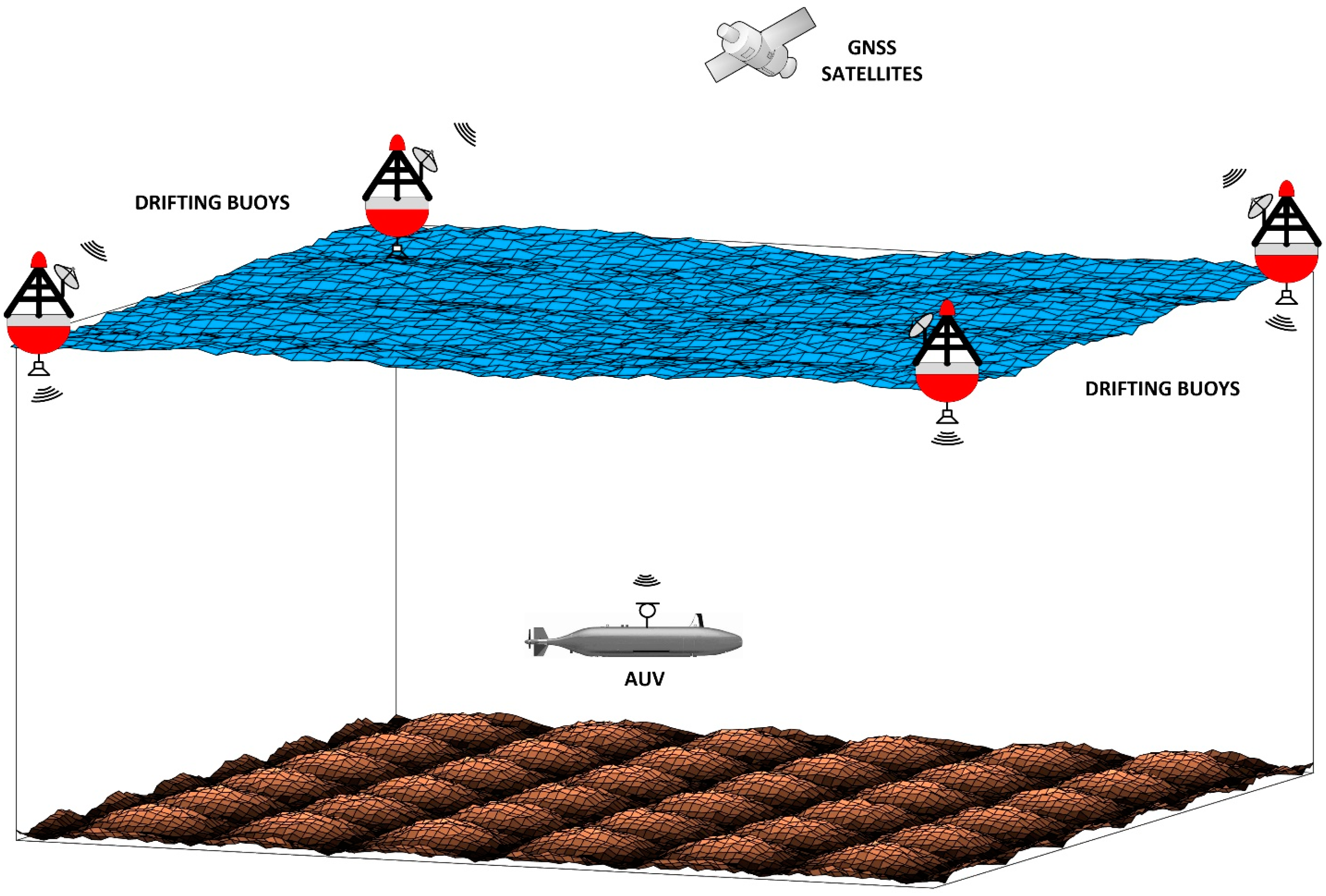
The proposed system consists of at least four surface buoys that transmit messages containing their GNSS-position and the GNSS-time at which the buoy position was computed.
Figure 1 shows a schematic view of the system. The buoys positions define a quadrilateral on the sea surface. For a greater coverage, the preferred quadrilateral is a square, but the system is still possible if the buoys are vertices of an irregular polygon.
Surface buoys can be fixed or drifting buoys, as will be soon be explained in
Section 3. The reason is that the data transmitted by each buoy are its GNSS position and the GNSS time at the instant of transmission, which are all that is needed by the receiver to calculate the position using the proposed algorithm. The buoys are not observation buoys, but a kind of “GNSS repeaters”. The buoys must be deployed following a favorable geometry. The best geometry is when they are at the vertices of a square. However, as long as they are not collinear, the underwater receivers will be able to calculate their positions. Basically, the hardware of a buoy consists of a microcontroller, a GNSS receiver, an underwater acoustic modem, including a hydrophone, and a power supply. They also incorporate a LoRa transceiver which is intended to facilitate the recovery of drifting buoys and may, in the future, facilitate the use of more than four buoys to increase the coverage region of the system. These buoys are inexpensive devices which pose no hazard to navigation and can be easily and quickly deployed for a specific underwater mission. The receiver onboard the underwater vehicle consists of an underwater acoustic modem and a microcontroller.
Each buoy transmits sequentially, through an underwater acoustic transmitter, a message containing its GNSS position and the time of the instant at which that position was calculated. All buoys use the GNSS time, so that we can consider that they are synchronized. All receivers that are in the acoustic communication range of four buoys can calculate their position. It is possible to demonstrate the feasibility of the buoy transmission schedule. The length of the message is estimated to be around 80 bytes. This number comes from the length of the complete frame of the standard NMEA [
13] and could be shortened if needed. Assuming a maximum limit of one second for the transmission time of a message, the minimum bit rate for the transmitter would be 640 bps, which is achievable with commercial underwater acoustic modems.
Concerning propagation time, one second roughly means 1.5 km range (the propagation speed depends on the salinity and temperature of the water and on depth), which is a long range in the world of underwater communications. A guard time of one second can be considered so far, which means a duty cycle of less than 10 s for the four buoys and a delay of around 8 s between the transmission of buoy #1 and the transmission of buoy #4.
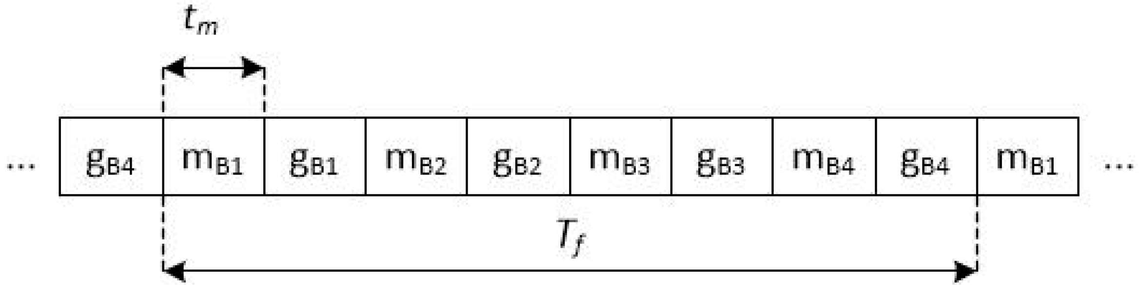
Figure 2 shows the frame structure.
If the coverage region is a cube of which one of the faces is the one with the four buoys as vertices, for the maximum distance between any of the buoys and any point inside that cube to be 1.5 km, the maximum side of the buoys square should be 1500/√3 m, that is, approximately 866 m. All of the above buoy spacing, guard time and range figures are indicative; their sole purpose is to confirm the feasibility of the system and they should be recalculated under the premise of a concrete system specification.
In
Figure 2,
mBi stands for the message transmitted by buoy
i, and
gBi is the guard time before buoy
i + 1 starts transmitting;
tm is the duration of the buoy message and
Tf is the length of a single frame, which is the period of the transmission of the four buoys. On the other hand, an AUV is unlikely to move faster than 10 knots, which is around 5 m/s. In 2 s, it would have moved 10 m. This figure can be roughly considered the upper bound of the intrinsic limitation of the system in terms of position accuracy. Nevertheless, in case a lower upper limit is required, the use of a higher data rate in the modem or the reduction of the guard time results in a shorter frame and, consequently, higher position accuracy.
3. Analytic Solution of the Multilateration Equations
The Time Difference of Arrival (TDoA) technique has been used extensively in many different engineering applications and is very well known. When the stations (or sensors or transmitters, depending on the configuration of the system) are far apart in terms of wavelength, the system is said to be hyperbolic, since the locus of the points that are a constant distance from two given points is a hyperboloid, the foci of which are the latter two points. If there are four stations, the intersection of the hyperboloids obtained by taking the foci two by two is the 3D position of the point sought. This technique is called multilateration and has received much attention from scientists and engineers since the beginning of hyperbolic systems such as LORAN (which was 2D and normally used three stations) followed by other systems up to the current GNSS systems. Among the many solutions to the multilateration problem, the ones we have preferred in this work are those of Kleusberg [
14] and Potluri [
15].
The analytical solution of the so-called multilateration problem is summarized below. So far, a constant sound propagation velocity c is assumed. The effective sound velocity can be used for c. As mentioned, the four buoys use the GNSS clock. Let be the instant of transmission of buoy i = 1, …, 4, and the instant of the reception of the corresponding message by the underwater receiver. The message transmitted by buoy i contains and the GNSS-position of the buoy, Ri.
Attention must be paid to the fact that the clock of
is the GNSS-time at buoy
i and the clock of
is the underwater receiver clock, which does not need to be synchronized with the GNSS time. That means that
and
are measured by different clocks. Let Δ
t be the offset between the two clocks. The so-called pseudorange between buoy
i and the receiver is calculated as
The difference of pseudoranges between buoys
i and
j and the receiver is
because the offset in the pseudoranges cancels out. That is, the receiver knows
Ri and
, which are the data that are needed to solve the multilateration problem.
As said, in this work, we followed three approaches to obtain the receiver position. First, we used the analytical solution of Kleusberg [
14] to verify the validity of the proposed solution of using four buoys transmitting their own position and time of transmission. We particularly liked the analytical solution of Kleusberg because of its elegance. The Kleusberg method can be used in the laboratory to test other algorithms, which is what has been done in this work. But this method only works if the solution exists. This means that there are combinations of pseudoranges that are theoretically impossible. Conceptually, the solution of the multilateration problem consists in finding the intersection of at least three hyperboloids. The intersection of two hyperboloids, if it exists, is a line in space. The lines resulting from intersecting the hyperboloids two by two in a real case do not have to intersect and then the Kleusberg method, which has the elegance of solving the problem analytically, does not provide the point where the receiver is located.
This means that the two lines resulting from the intersection of four hyperboloids taken two by two may not cut each other in space but cross each other. Therefore, we also used a second approach inspired by the work by Potluri [
15] and particularized it to the underwater scenario. Finally, we proposed a third approach that simplifies the solution, based on using the position of one of the buoys as a reference for the positions of the other three buoys.
Our approach, which proves to be a valuable technique, is to use the depth data from the depth sensor fitted to the underwater vehicle. In that case, only two equations are needed to compute the coordinates x and y of the receiver. This technique is valuable for the following reason. If the four buoys are coplanar, as is the case, a bidimensional (2D) reference world is used to compute a 3D position. This makes the computed value of the receiver z-coordinate very sensitive to small errors due to numerical mismatches.
For this reason, we have designed a third strategy for the solution of the multilateration problem. We have referenced the coordinates of three of the buoys to the position of one of them, to which we have given the index 0. The difference of distances between the receiver and buoy
i (
i = 1, 2, 3) and buoy 0 is
where now
i = 1, 2, 3. If Equation (3) is squared, the terms in
x2,
y2 and
z2 cancel out and can be written as
where
If the right-hand members of the three equations in (4) are equated two by two, a linear system of three equations is obtained
Only two of the three equations in (7) are linearly independent and to obtain the receiver position, RR, we must also use (4). The point here is that if again z0 = z1 = z2 = z3 ∀i,j, then Ci = Cj and the two independent equations in (7) give the sought coordinates x and y. This brings us back to the discussion on the calculation of a 3D position from a 2D reference. The problem is overcome by using the value of z = zd that can be obtained from the depth sensor of the underwater vehicle.
4. Results
The analytical solution has been tested using the reverse calculation. The test consists in placing four buoys on the sea surface and a receiver in determined underwater positions. That is, the GNSS positions of the four buoys are known. Pseudoranges are calculated and, eventually, the eight values of
and
. A stationary receiver has been considered. The four messages are formed and given to the receiver, that computes its position using the analytical solution presented in
Section 3 and it is found to be exact.
As mentioned in
Section 1, one of the limitations of the presented positioning system is the movement of the receiver, because buoys do not transmit simultaneously, and because the propagation delay of the acoustic wave cannot be neglected.
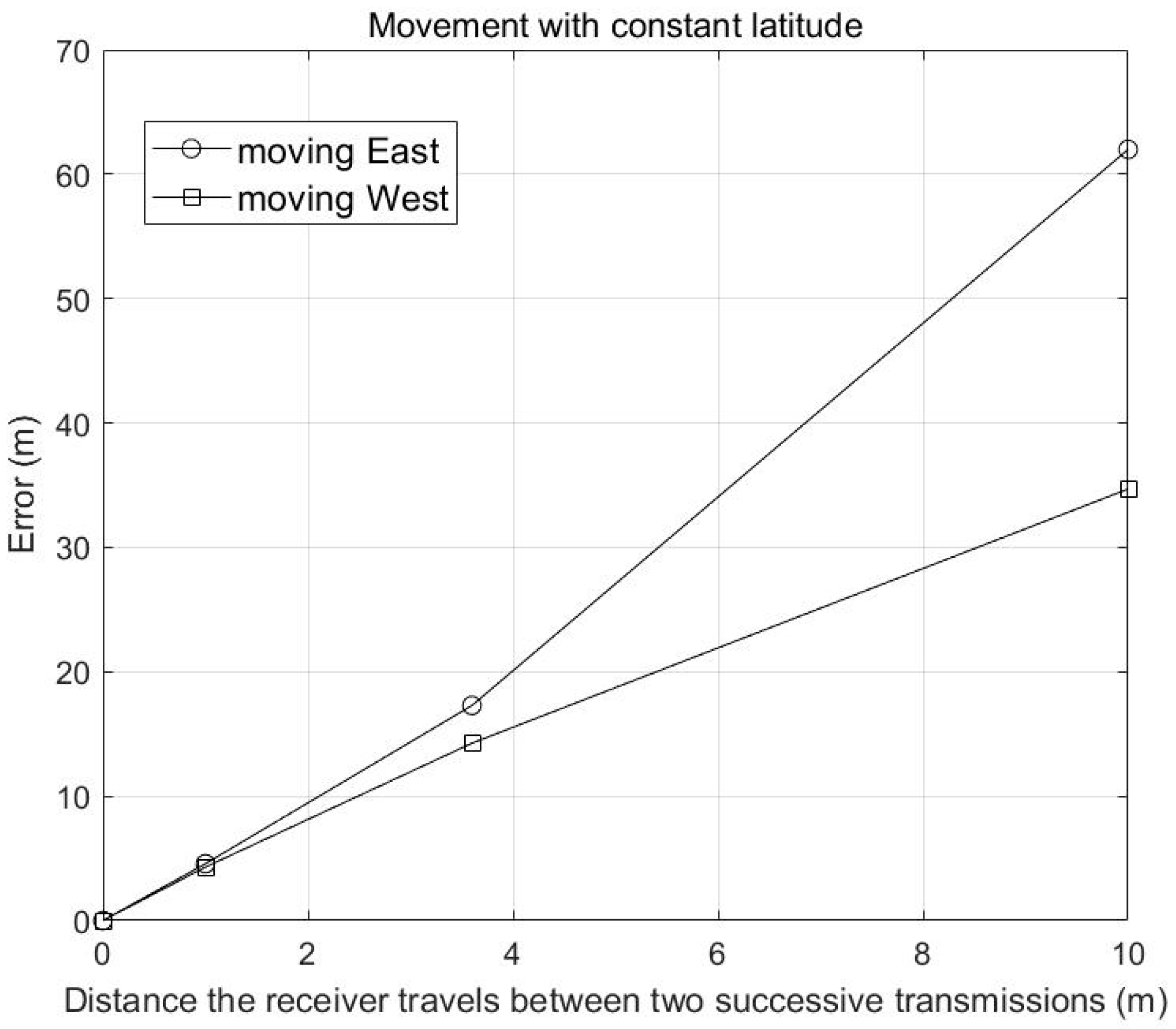
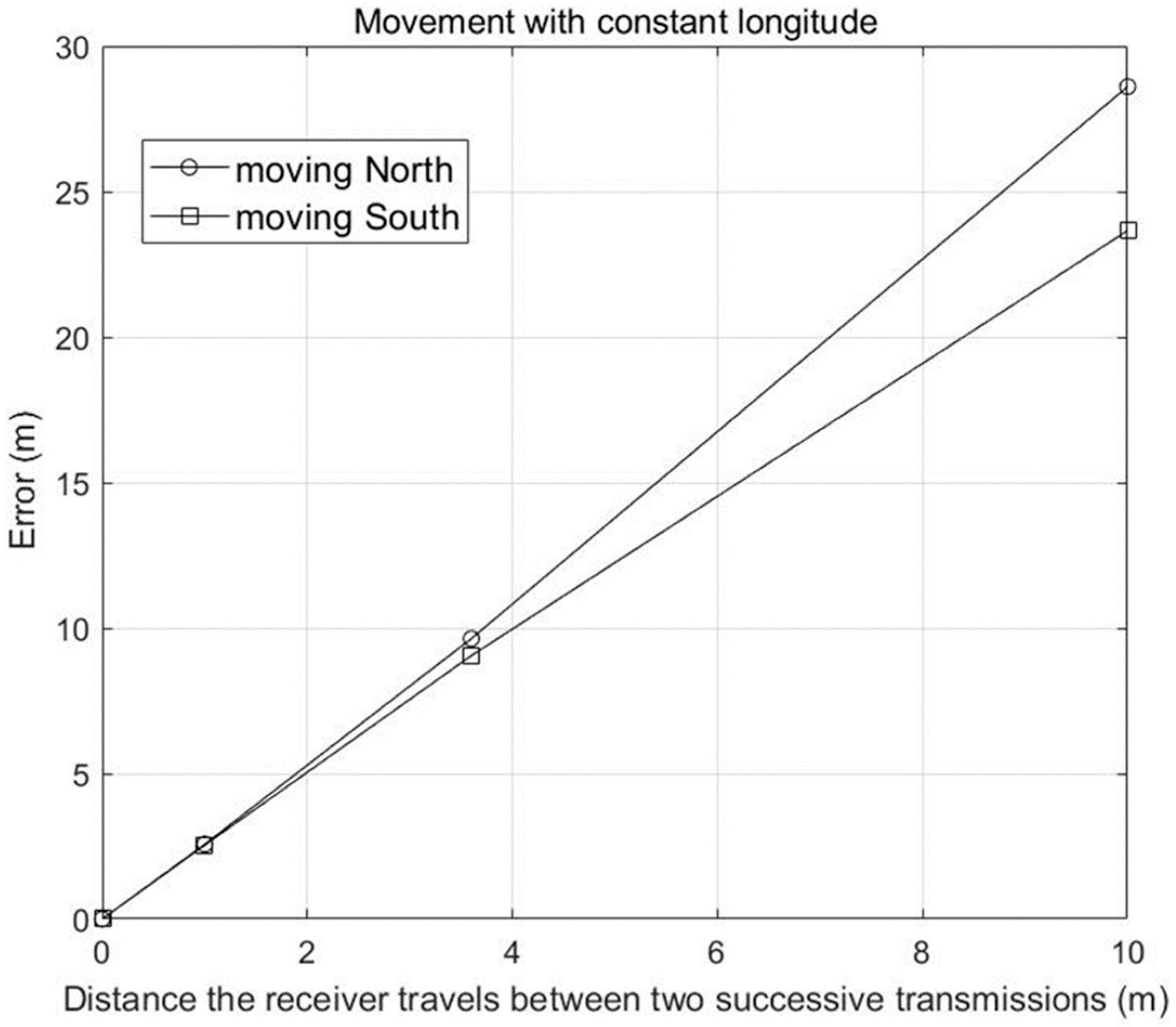
Figure 3 and
Figure 4 show the error vs. the receiver speed, when moving along a parallel or a meridian, respectively. The error is calculated by placing the submerged receiver in the various different positions it would be in when transmitting each buoy (because of its movement). Obviously, the ToA differences are not those that would be present if the receiver were at a fixed point. These time differences were used to calculate the position with the presented algorithm and compared with the position of the receiver after receiving the signal from the fourth buoy. The shown error is the distance in meters between these two positions and it has been computed for different receiver velocities. Geographical coordinates of the receiver position for the test were approximately (N36°, W4°). The distance shown on the horizontal axis is the distance the receiver travels between two successive transmissions from the transmitters on the buoys. That is, if the time between two successive transmissions is
(see
Figure 2), then the receiver speed is the abscissa shown divided by Δ
T. For example, if the distance is 3.4 m and the transmission interval is 2 s, the receiver speed is 1.7 m/s. Obviously, the lower Δ
T the smaller the error. The error depends not only on the receiver velocity and Δ
T, but also on the relative position of the receiver with respect to the polygon whose four vertices are the positions of the buoys, and on the direction of motion. The reference to the cardinal points is also relative; for the error, the direction of movement is relative to the rotation of the buoy transmission (clockwise or counterclockwise).
Figure 3 and
Figure 4 show values that have been obtained in different examples. The error in
Figure 3 is the largest error obtained in different calculations.
There is an interesting debate on how to reduce this error. As already mentioned, the lower Δ
T the smaller the error, but Δ
T has a lower value which depends, among other things, on the propagation velocity of the acoustic wave in water, which is a physical constraint. The operational solution of stopping the underwater vehicle for a short period of time while the receiver calculates the position is always possible, but the sea current will always be present. The technological option is to use sensor data fusion, which has proven to be an effective way to reduce the error in underwater positioning [
16,
17]. In addition, the data fusion system can help compensate for sea current drift to maintain a stable position while calculating.
5. Conclusions
In this article a GNSS repeater system has been presented to provide underwater positioning using four acoustic transmitters mounted on surface buoys. The main contribution of the chart is that the underwater receiver clock does not need to be synchronized with the buoy clocks or be a very accurate atomic clock. The proof of concept has been carried out using the Kleusberg analytical method to solve the multilateration problem, and the feasibility of the time schedule has also been demonstrated. Finally, a multilateration algorithm derived from Potluri’s algorithm has been used to compute the receiver position.
As mentioned in
Section 2, the drifting of the buoys is not a limitation because the buoys sequentially transmit their position at a particular instant and the time of the instant of transmission, which are all the receiver algorithm needs to calculate the difference of pseudoranges.
Regarding the system limitations, the following can be mentioned. The service range is limited by the communication range of the underwater acoustic communication system. The position accuracy is limited by the transmission bit rate of the above-mentioned system, as explained in
Section 2, and the receiver movement, as shown in
Section 4. There is no limitation on the number of receivers that the system can serve, as long as they are in the range of four buoys.


