Review

Exploring Autonomous and Remotely Operated Vehicles in Offshore Structure Inspections

by
Maricruz Fun Sang Cepeda
1,
Marcos de Souza Freitas Machado
1,
Fabrício Hudson Sousa Barbosa
1,
Douglas Santana Souza Moreira
1,
Maria José Legaz Almansa
2,
Marcelo Igor Lourenço de Souza
3 and
Jean-David Caprace
3,*
1
Department Naval and Fisheries, Rio de Janeiro State University (UERJ), Rio de Janeiro 23070-200, Brazil
2
Department of Applied Physics and Naval Technology, Polytechnic University of Cartagena (UPCT), 30202 Cartagena, Spain
3
Department of Naval and Oceanic Engineering, Federal University of Rio de Janeiro (UFRJ), Rio de Janeiro 21941-611, Brazil
*
Author to whom correspondence should be addressed.
J. Mar. Sci. Eng. 2023, 11(11), 2172; https://doi.org/10.3390/jmse11112172
Submission received: 16 August 2023 / Revised: 17 October 2023 / Accepted: 23 October 2023 / Published: 15 November 2023

Abstract

:
Operators of offshore production units (OPUs) employ risk-based assessment (RBA) techniques in order to minimise inspection expenses while maintaining risks at an acceptable level. However, when human divers and workers are involved in inspections conducted at high heights, the operational risks can be significant. Recently, there has been a growing trend towards the use of unmanned aerial vehicles (UAVs), autonomous surface vehicles (ASVs), remotely operated vehicles (ROVs), and autonomous underwater vehicles (AUVs) for inspections of offshore structures as a means to reduce exposure to human risk. This article provides an analysis of these vehicle inspection capabilities and their potential to enhance robustness and safety within the oil and gas industry. The review assesses both the advantages and the drawbacks associated with these innovative systems, providing valuable comparisons and assessments on their potential use as viable alternatives to conventional inspection methods.

1. Introduction

1.1. Context

The offshore industry is experiencing rapid growth and technological advancement in exploration, collection, and storage. This progress is accompanied by a commitment to improving safety measures to minimise the risk of accidents [1]. Although occasional incidents pose environmental and human risks, the industry has adopted preventive measures and response strategies, demonstrating ongoing commitment to safety [2].

1.2. Challenges of Traditional Offshore Inspection Methods

The current offshore inspection methods face several issues that hinder their effectiveness and efficiency. One of the main issues is the reliance on traditional inspection techniques, such as visual inspection and nondestructive testing (NDT), which are often time-consuming, costly, and limited in their ability to access hard-to-reach areas [3]. These methods require human intervention and are subject to human error, which makes them less reliable [4]. Furthermore, offshore installations are subject to perpetual fatigue loading and harsh marine environments, which can cause structural degradation and damage [5]. Current inspection methods may not be able to accurately detect and assess the extent of such damage, putting the integrity and safety of offshore structures at risk [6].
Another issue is the lack of comprehensive risk-based inspection planning (RBI) for offshore installations [4]. RBI involves assessing the risks associated with the operation of offshore facilities and developing inspection plans based on the identified risks [7]. However, the implementation of RBI in the offshore industry has been limited and a more systematic and integrated approach to RBI is required [4]. This is particularly important for offshore wind turbines, which are expected to continue to develop in deep ocean areas in the coming years [8].
Furthermore, current inspection methods may not be able to effectively monitor the health and safety of offshore structures in real time [8]. Traditional inspection techniques often provide a snapshot of the current condition of the structure, but do not provide continuous monitoring or early detection of potential problems [3]. This can lead to unexpected failures and higher maintenance costs [9]. Advanced monitoring systems are needed to continuously collect data on the structural health of offshore installations and provide real-time feedback on their condition [8].
Moreover, current inspection methods may not be cost-effective, especially considering the large number of offshore structures and the challenging marine environments in which they operate [10]. Traditional inspection techniques require significant resources, including manpower, equipment, and time, which can result in high inspection and maintenance costs [10]. It is essential to find a cost-effective way to plan inspection and maintenance activities that takes into account the probability, consequences, and cost of these activities [10]. It is necessary to investigate alternative methods to reduce expenses while still maintaining a high level of accuracy and quality both above and below the water.

1.3. Advancements in Autonomous Technologies

To address these issues, there have been efforts to develop and implement new inspection technologies and methodologies in the offshore industry that provide more efficient and cost-effective solutions while minimising human risk [11]. These include the use of autonomous vehicles such as autonomous underwater vehicles (AUVs), remotely operated vehicles (ROVs), unmanned aerial vehicles (UAVs), and autonomous surface vehicles (ASVs).
As noted in [12], these alternatives must be able to provide accurate and reliable information on the condition of the equipment, even in challenging environments such as thousands of metres below the ocean surface.
Remotely operated vehicles (ROVs) and autonomous underwater vehicles (AUVs) have become key players in the offshore industry, each offering unique advantages [13,14].
ROVs are tethered vehicles that are remotely operated by human operators. They are commonly used for routine inspection tasks at subsea oil and gas installations and can perform light interventions, as discussed by [15,16]. ROVs provide real-time video feeds and high-resolution imaging capabilities, allowing operators to visually inspect and assess the condition of offshore structures [17]. This makes them especially valuable for detailed close inspections that require high-resolution imagery and advanced sensory data. Their ability to be controlled in real time also allows for an immediate response to obstacles or changes in mission parameters.
AUVs, on the other hand, which operate independently of surface vessels, have distinct advantages in range, manoeuvrability, and deployment flexibility [18]. These advantages are particularly significant in complex environments where tethers can restrict operations. The absence of a tether greatly reduces the risk of entanglement with subsea structures and allows the AUV to dive deeper and faster. They are equipped with advanced instrumentation and measurement systems to perform subaquatic tasks and gather data for analysis, as shown by [18,19]. AUVs have also been used to map the seafloor and inspect cable and pipelines under the ocean surface, utilising multimodal sonar sensors for accurate mapping and monitoring [20]. AUVs have recently undergone significant advancements in terms of operational range and endurance due to the new battery technology, and certain AUV models are now capable of several days of autonomous operation, as recently demonstrated by the HUGIN© endurance AUV. Lastly, waves and impacts of underwater currents on the tether are of great concern for ROVs because they may cause them to be swept away or limit their controllability. AUVs are immune to this limitation, allowing operations under more challenging weather conditions.
Similarly, the industry has shown a recent interest in using autonomous surface vessels (ASVs) and unmanned aerial vehicles (UAVs) for the inspection of ocean structures that are above the sea water, as shown by [21]. These emerging technologies have established themselves as essential tools due to their distinct advantages and benefits.
As widely discussed by [22], ASVs are highly adaptable for collecting data on both the ocean surface and the subsurface environment, making them a reliable choice even in harsh sea conditions. These vehicles have the ability to navigate independently around offshore structures while collecting data using integrated sensors including multibeam echosounders and side-scan sonars [23]. By minimising human error and reducing risks associated with manned operations, ASVs greatly improve the efficiency of maintenance schedules and potential threat assessments. These vehicles are designed to operate in harsh ocean environments and reduce human participation in offshore infrastructure monitoring [20].
Autonomous UAV technology, also called drones, has emerged as a crucial tool for conducting inspections above the waterline. These UAVs possess the ability to access difficult-to-reach areas on floating platforms and other ocean structures, enabling them to capture detailed high-resolution imagery that offers essential information for structural health monitoring, as shown by [24,25]. With their agile manoeuvrability and advanced imaging technologies, drones can quickly detect problems such as corrosion or mechanical damage, allowing for prompt remedial actions. Some even have the capacity to climb structures [26]. Furthermore, by reducing the need for inspectors to work at great heights or in hazardous conditions, drones significantly improve safety during inspections.

1.4. Recommendations for Offshore Inspections

All these vehicles are equipped with advanced sensors and imaging systems that can capture high-resolution images, video footage, and other data to assess the condition of subsea equipment. As recently shown by [27], the utilisation of underwater laser line scanners and close-range photogrammetry has shown potential as optical survey methods for subsea inspection. These innovative technologies enable scanning of the entire scene, facilitating comprehensive reconstruction of its 3D structure through the processing of a 3D point cloud.
These technologies can be used to analyze large amounts of data collected from subsea inspections and identify patterns or anomalies that may indicate potential issues or areas of concern. Furthermore, the use of advanced sensors and imaging technologies can enhance the capabilities of autonomous underwater vehicles and unmanned surface vessels for subsea inspection [28].
Reducing inspection costs is a key driver behind the industry’s recent interest in utilising advanced technologies such as autonomous vehicles. As stated by [29,30], inspections can be complex and costly, especially when dealing with large structures or covering long distances at significant depths. Therefore, finding ways to decrease expenses while maintaining high quality and accuracy above and below water has become an important challenge for the industry. In fact, inspection costs often account for a substantial portion of operational expenditures.
As a result, researchers have been investigating alternative approaches to reduce costs and enhance efficiency in inspections. One such approach involves the utilisation of autonomous surface vehicles, autonomous underwater vehicles, remotely operated vehicles, and drones for inspection purposes.
Risk-based inspection (RBI) planning has also been a focus of development in the field of offshore structure inspections. By considering the probability, consequences, and cost of operational or maintenance activities, risk-based inspection frameworks enable optimal selection and prioritisation of inspection and maintenance activities [10]. These frameworks use structural reliability methods and Bayesian reliability methods to establish fatigue design criteria and update inspection plans during operation [31]. RBI involves prioritising inspections based on the level of risk associated with each subsea asset, thus reducing the need for systematic periodic inspections where they are unnecessary. By conducting a thorough risk assessment, operators can determine which assets require frequent inspections and which can be inspected less frequently.
Another approach is to take advantage of advanced technologies such as artificial intelligence (AI) and machine learning algorithms to improve the efficiency and effectiveness of subsea inspections. Several authors discuss the use of AI to improve vehicle self-awareness [32] or the ability to detect and follow objects [33].
For instance, the authors of [34] discusses the automation of the detection and classification of marine growth in offshore structures using deep learning and sensors to obtain a 3D representation of thickness and composition. The study also highlights the need for further development given the impact of marine growth on structural integrity due to increased hydrodynamic loads. Similarly, ref. [35] discuss the use of AUVs and AI in inspecting, maintaining, and detecting damage in subsea oil and gas pipelines that compromise their structural integrity. Despite improvements in image-based inspections and computer vision methods for subsea environments, the authors underline the challenges of the lack of training data for image analysis and the incorporation of risk-based knowledge.
In essence, the combination of ROV, AUV, ASV, and UAV technologies provides a holistic approach to reduce inspection costs, particularly for large structures and deep-sea operations. Utilizing autonomous vehicles, implementing risk-based inspection strategies, and leveraging artificial intelligence (AI) and machine learning can enhance inspection efficiency and reduce expenses. Careful planning ensures optimal inspection schedules that maintain desired risk levels at minimal costs. Using these methods, companies can efficiently monitor total structural health, ensuring extended operational longevity and safety while reducing operational costs.

1.5. Content of the Paper

Offshore production units (OPUs) continuously explore methods for safe yet cost-effective inspections of their infrastructures. Traditional human-conducted inspections can involve high operational risks, due to the hazardous environments such as high heights or deep-sea situations. Recent advances in technology have resulted in viable alternatives, with a growing trend in the use of unmanned vehicles such as unmanned aerial vehicles (UAVs), autonomous surface vehicles (ASVs), remotely operated vehicles (ROVs), and autonomous underwater vehicles (AUVs) for inspection tasks.
This paper seeks to explore these emerging technologies, assess their potentials and limitations compared to traditional methods, and recommend the optimal use for each type of offshore structure. The article begins by explaining the requirements of offshore structure inspections, followed by a discussion on the challenges of traditional methods. Subsequently, we analyse each innovative vehicle, highlighting their advantages and potential improvements. Finally, we provide a comparative summary and make recommendations for the adoption of these new technologies based on each specific zone in offshore structures.

2. Inspection Requirements for Offshore Production Units

To determine the effectiveness and suitability of vehicle inspection technologies, it is important to have a clear understanding of the inspection needs of offshore production units. Offshore production units, such as oil rigs and platforms, and more recently offshore wind turbines [36], must comply with various safety regulations and undergo regular inspections. These inspections are conducted to verify the integrity and functionality of the equipment, identify potential dangers or problems, and ensure compliance with safety standards. Structural integrity management (SIM) is an organised approach that aims to ensure the long-term reliability and durability of physical structures [12,28,37]. It encompasses various aspects such as human resources, systems, procedures, and assets.
In order to adhere to the inspection needs of offshore production units, it is essential to comprehend and address the unique obstacles and circumstances that these structures encounter. Maintaining the SIM plays a critical role in ensuring the safety and reliability of OPUs. This is achieved through regular inspections conducted in various areas of the platform (see Section 2.1) with the objective of identifying potential risks or damages that could jeopardise personnel, assets, and environmental integrity. These inspections are not only obligatory for regulatory compliance, but also serve as proactive measures aimed at avoiding costly incidents and failures.
Offshore production units can be divided into several zones of inspection depending on the accessibility of the asset and methodologies available to perform the inspection.

2.1. Zones of Inspections

In accordance with the literature, the authors of this paper suggest a division of offshore structures into the following zones [Z*] (see Figure 1):
Z1
Superstructure (from the lower deck to the upper mast): This refers to the upper part of the offshore platform, including living quarters, helidecks, and process equipment (modules). Inspections in this zone are crucial to ensure the safety and functionality of the equipment and structures located on the topside [38]. The accessibility of this zone is relatively easier compared to other areas, as it can be reached by personnel and equipment through stairs or elevators, except for some specific structures, such as flares and towers.
Z2
Splash/Spray zone (from the waterline to the lower deck): This zone is located above the waterline and includes areas that are exposed to waves, wind, and occasional splashes of seawater. Inspections in the splash/spray zone are crucial, as this area is susceptible to corrosion and degradation as a result of exposure to harsh environmental conditions [39]. However, this area is difficult to access and requires specialised equipment and techniques for inspection (climbing).
Z3
Subsea zone near the water line (below the water line up to 50 m depth): This zone encompasses the hull of the floating/fixed platform [40], as well as the equipment and connections of the risers. Inspections in this subsea zone are crucial to ensure the integrity of the hull and the proper functioning of the risers [12]. Accessing this zone for inspections can be challenging, as it commonly requires diving. Today, common ROVs and AUVs cannot operate in this depth due to limitations in their capabilities and manoeuvrability.
Z4
Subsea dynamic zone (from 50 m depth until the touchdown point (TDP) and pipe anchoring system laying on the seabed): This zone includes the risers that carry hydrocarbons from the subsea wells to the top-side processing facility [37]. Inspections in this subsea dynamic zone are critical in identifying potential defects or damage to the risers that could lead to leaks or failures. Inspections in this zone are particularly challenging due to the extreme depths and harsh conditions encountered. The “vertical” position of the pipes and their movements may make the inspection process difficult.
Z5
Subsea submerged zone (all assets laying on the seabed): This zone encompasses all assets located on the seabed, such as pipelines, structures, and equipment [28]. Inspections in this submerged subsea zone are essential to detect any damage, corrosion, or integrity issues that could affect the safety and reliability of the assets [41]. This area may be easier to inspect, as the pipes are horizontal and fixed on the seabed. However, from time to time, the equipment may be submerged in sediment or covered with marine growth, making inspections more challenging.
It is important to recognise that certain structural components can extend over several areas, requiring a range of inspection techniques within each zone. This emphasises the need for a comprehensive selection of inspection methods to effectively assess various aspects of these complex elements; see Table 1.

3. Common Approaches of Offshore Inspection

It should be emphasised that the traditional method used in inspection operations heavily depends on visual inspections. This method effectively identifies various anomalies such as damage (e.g. abrasion, rupture, leakage, and deformations) present on the outer covering of a submarine system. Additionally, it can also detect failures in relief valves located at the top section and identify errors in ship positioning for floating platforms. There are two primary techniques used for visual inspections: General Visual Inspection (GVI) and Close Visual Inspection (CVI). GVI involves using cameras mounted on ROVs or AUVs to visually detect damage and leaks. On the other hand, CVI requires more thorough cleaning processes and is typically employed to examine welds, corrosion levels, and cracks. These visual inspection techniques, although widely used and effective in detecting surface-level issues, have limitations when it comes to assessing the overall health and condition of underwater structures.
Common approaches to offshore inspection include mainly the use of inspectors for the superstructure (zone 1), climbing workers for the splash/spray area (zone 2), divers for the subsea area near the water line (zone 3), and remotely operated vehicles for the dynamic subsea zone (zone 4) and underwater zone (zone 5) [42]. However, in recent years, offshore companies have been trying to improve inspection efficiency while reducing risks to human life. This has led to the adoption of technological advancements in inspection techniques, such as the use of UAVs and ASVs (zones 1 and 2), mini ROVs (zone 3), advanced inspection systems (zone 4), and AUVs (zone 5). These technological advancements have revolutionised the inspection process by offering greater mobility, remote monitoring capabilities, and better accessibility to difficult-to-reach areas.
The use of drones in zones 1 and 2 allows for more efficient inspections of the superstructure and splash/spray area, reducing the need for human inspectors to physically climb or access these areas. Furthermore, drones equipped with high-resolution cameras and sensors can provide detailed visual imagery and data for analysis, allowing operators to identify potential problems or defects without the need for direct physical inspection. Similarly, mini ROVs have become popular for inspections in zone 3, as they can navigate the subsea area near the water line with greater agility and flexibility compared to human divers. Advanced inspection systems and autonomous underwater vehicles are used in zones 4 and 5, respectively. These advanced technologies offer the advantage of collecting data on the states of the subsea structure without the need for humans to operate them.
The following section aims to provide an overview of the possible use of autonomous and remotely operated vehicles for inspecting offshore structures.

4. State of the Art of Autonomous and Remotely Operated Vehicles in Offshore Structure Inspections

In order to enhance the inspection of offshore structures, various vehicle technologies can be utilised. As previously mentioned, these include unmanned aerial vehicles (drones), remotely operated vehicles (ROVs), autonomous underwater vehicles (AUVs), and autonomous surface vehicles (ASVs).
Based on the data presented in Figure 2, it is evident that extensive research has been carried out on all four types of autonomous and remotely operated vehicles discussed in this paper. The increase in publications can be attributed to advancements in sensor technology, artificial intelligence, and autonomy. Interestingly, both ROVs and ASVs have similar quantities of papers and citations, while AUVs appear to have fewer publications. In contrast, there has been a significant surge of interest among researchers regarding drones over the past decade, as evidenced by the considerably higher number of publications compared to other vehicle types. This rise may be due to the increased accessibility of drone technology for purposes beyond academic research or military use.

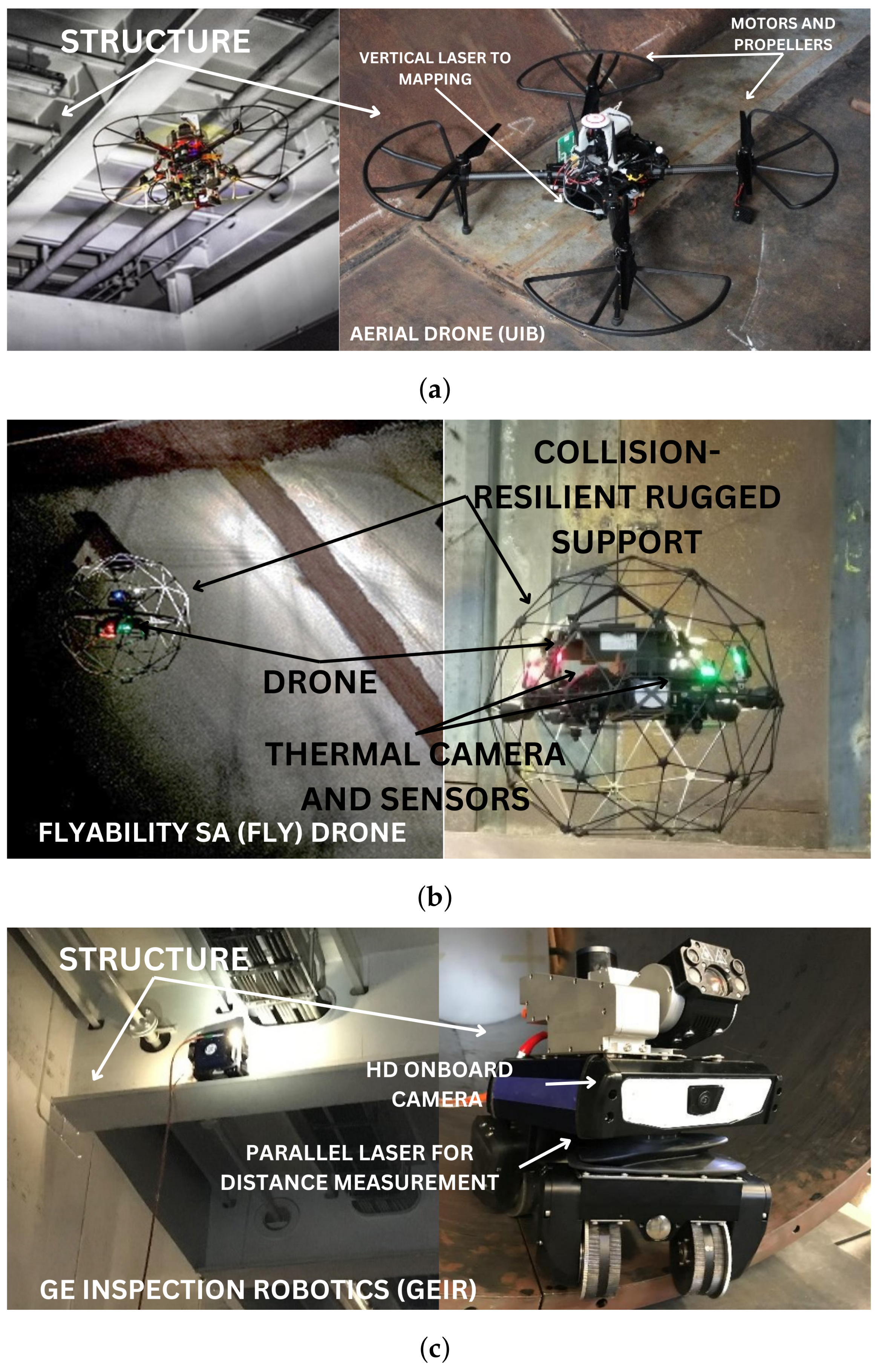
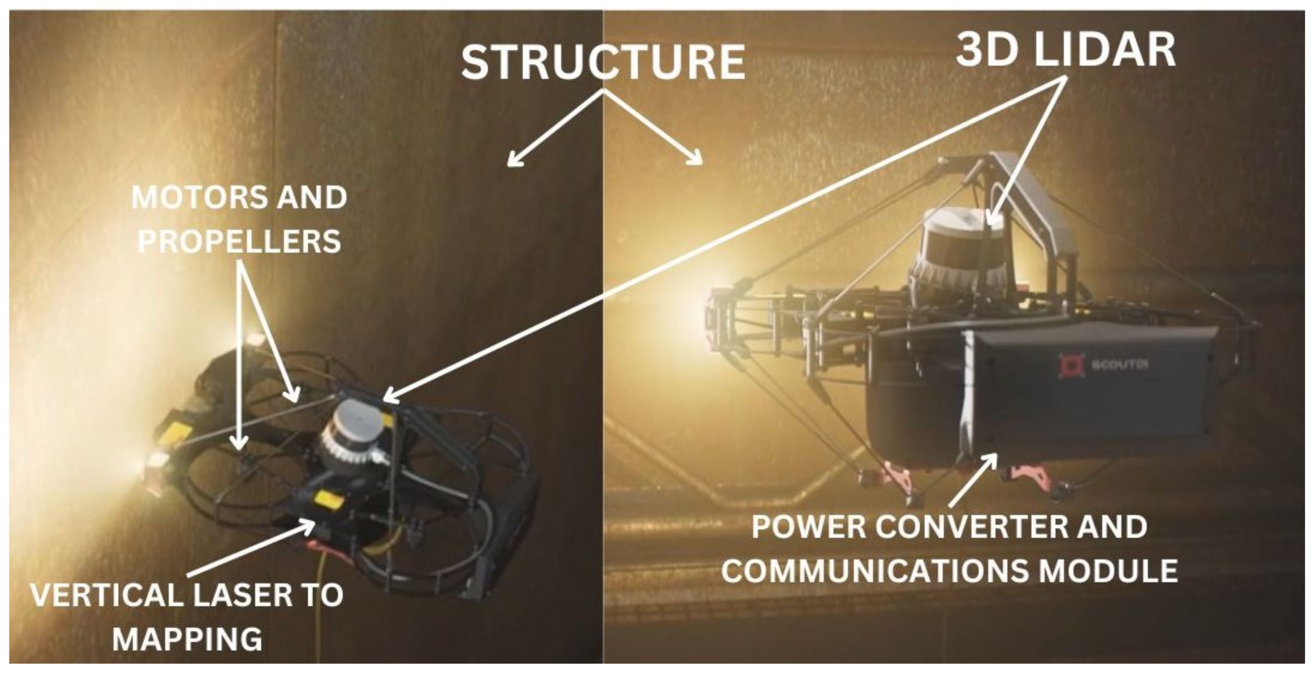
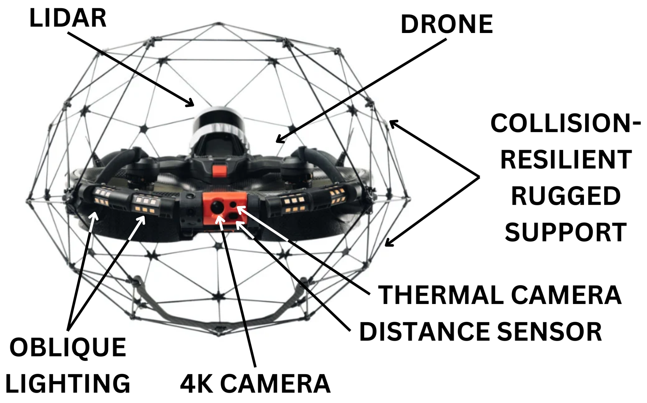
4.1. Unmanned Aerial Vehicle (UAV)—Drones

With the advancement of technology, unmanned aerial vehicles, also known as drones, have become a prominent tool for data collection and visual evaluations. Drones are typically categorised into multi-rotor and fixed-wing types, each with its unique uses and characteristics; see Figure 3. For offshore structure inspection, multi-rotor drones are commonly used due to their ability to hover and manoeuvre in tight spaces. Their use spans different fields, including agriculture for agrochemical transportation, mapping purposes, and inspections within the civil and industrial sectors.
Drones have become increasingly popular for inspection of offshore structures, particularly in zones 1 and 2. Equipped with high-resolution cameras and sensors, drones offer enhanced visibility and remote monitoring capabilities. They can capture detailed visual imagery and data for analysis, allowing operators to identify potential problems or defects without the need for direct physical inspection. Drones can be used to inspect various zones in offshore structures, including the following:
  • Hull: Drones can provide a detailed view of any part of the hull of a ship, identifying sections with corrosion, cracks, or other damage.
  • Riser balconies: These are critical points on an offshore platform. Drones can reach difficult-to-access places to inspect these areas.
  • Topside: The upper portion of an offshore structure can be easily inspected by drones to check for structural integrity, leakage, weather-induced damage, etc.
  • Flare stacks: Inspections of flare stacks are necessary to check for corrosion, cracks, or blockages. Drones can perform this task without the need to stop operations.
  • Internal tanks: Specialised drones can even inspect the interiors of large storage tanks on ships and units, including corrosion and leakage detection assessments.
  • Hard-to-reach areas (underdecks, cranes, etc.): Drones can reach places that would be dangerous or difficult for humans to access, enabling inspection of complex areas, such as underdecks or cranes.
In essence, drones have significant versatility and can be used for most inspections in practically all upper areas of naval and offshore infrastructure.
Kneipp (2018) alongside Santos (2023) present the potential of using drones for inspection in the naval and offshore industry, particularly within the Brazilian context [43,44]. It discusses the time-optimising benefits of drone inspection methods, highlighting their ability to reach difficult-to-access places and detect issues like corrosion, cracks, and leaks. The author proposes possible applications of drone inspections on a floating production storage and loading (FPSO) platform. It also outlines the best types of drone for such applications and navigates the regulations surrounding drone operations. Finally, it encompasses discussions on solutions such as 360-degree videos, 3D modelling for measurements and volumes, and image-based structure analysis.
Drones provide a variety of benefits in terms of agility, cost-effectiveness, flexibility, security measures, and the ability to provide frequent information updates. These unmanned aerial vehicles are equipped with active and passive sensors to enhance their functionality. Active sensors such as LIDAR and RADAR enable them to collect data through signal transmission, while passive sensors such as visual spectrum and thermal cameras capture images without the need for signal transmission [45]. Moreover, photogrammetry is a common method used by drones for image analysis in inspections. This involves capturing a series of overlapping images from different angles and using computer algorithms to stitch them together, creating detailed 3D models that can be used for further analysis and measurements [46].
Drones can also be used for confined space inspections on ships where human access is limited. It includes the inspections described by Frederiksen et al. (2018) and Krystosik (2021), including examinations of hulls, ballast and cargo tanks, coating systems, and structural integrity. Drones are also used to inspect crane tops, flares, confined spaces, and inaccessible areas during routine inspections, such as the exterior of the hulls (inaccessible) or the interior of tanks. Additionally, drones may aid in damage inspection following incidents and assessments before reactivating ships [47,48].
Poggi et al. (2020) identified challenges for the use of robotics and autonomous systems (RAS), including drones, in offshore inspections [49]. This includes the management of electromagnetic field disturbances, the limitation of GPS in internal space, the detection of obstacles, the management of reflective surfaces, and the negotiation with air turbulence. To address these challenges, various technologies are deployed, including vision-based camera inspections, 2D and 3D laser scanners, depth and RGB-D cameras, along with wireless-based location methods. The study finds several advantages to using RAS, leading to important conclusions. First, RAS significantly reduces human risk during inspection processes, as machines are deployed in areas where human access could be hazardous. Second, RAS inspections generate larger volumes of data in a shorter period, fostering efficient inspection processes. Finally, human-based inspections are often more expensive than RAS inspections, reaffirming the cost-effectiveness of using automated systems for offshore evaluations.
Numerous research teams have developed their own assortment of drones equipped with inspection functions. In the ROBINS project [49], a diverse range of RAS platforms were chosen to address the comprehensive needs of ship inspection, except underwater vehicles, which have been actively adopted for underwater inspections for some time now. The variety included two distinct types of aerial drones and a magnetic crawler, harnessing the unique capabilities of different robotic solutions to fulfil various inspection requirements. Moreover, the project anticipates conducting open trials with other robotic platforms in the future. The specified RAS units, conceptualised and created by Universitat de les Illes Balears (UIB), Flyability Sa (FLY), and Ge Inspection Robotics (GEIR), are depicted in Figure 4. These platforms showcase the potential synergies and capabilities offered by combining different robotic technologies to meet the extensive and varied needs of ship inspections.
The ADRASSO project, led by DNV Maritime, has undertaken extensive research and development in the field of semi-autonomous drone navigation. Furthermore, the project has focussed on utilising AI-based computer vision techniques for automated crack detection and hyperspectral imaging analysis to evaluate the condition of protective paint used in steel tanks as well as identify their chemical composition [48,50]. Demonstrations were successfully conducted onboard floating production, storage, and offloading platforms (FPSO) during this initiative (Figure 5). Notably, several other partners have collaborated with DNV Maritime on this endeavour including Jotun, Norsk Elektro Optikk, Idletechs Scout Drone Inspection, and NTNU.
The REDHUS project, which began in January 2021, is an ongoing initiative following the previous project. Its acronym stands for “Remote Drone-based Ship Hull Survey”. The primary objective of this effort is to showcase a streamlined procedure for conducting ship hull or tank surveys remotely through automated drone inspections and analysis of video data captured by the drones. By establishing this method as a standard practice in the future, ship owners can experience improved safety measures and economic gains. Furthermore, consistent delivery of high-quality inspection data improves the classification process while also allowing room for long-term advances. As a result of these developments, new market opportunities emerge not only for drone service providers, but also for technology suppliers, a mutually beneficial outcome.
With technology similar to the REDHUS development, we can highlight the ELIOS 3 drone (Figure 6), which has recently performed an inspection in FPSO tanks and ballast tanks for offshore companies and shipyards.
In conclusion, the use of drones in the maritime sector has proven to be highly beneficial. Advances in drone technology have enabled efficient inspections and surveys of ships and offshore structures. Drones offer advantages such as accessibility, easy operation, good camera control, and operation in confined areas for multi-rotor drones. Several successful demonstrations have already been conducted using autonomous drone technology in the maritime sector.

4.2. Remotely Operated Vehicles (ROV)

The inception of remotely operated vehicles can be traced back to the 1950s, where their initial use was focussed on retrieving torpedoes and mines. Following this early stage, a phase of iterative advancement emerged primarily driven by military applications but subsequently expanded into offshore tasks. Throughout the past several decades, ROVs have improved significantly in terms of their capabilities, particularly work-class ROVs that are capable of performing various underwater operations. Similarly to human divers, these ROVs are based on support vessels and are typically connected to them through an umbilical cord, which serves as a conduit for crucial communication and control data.
ROVs have the ability to be utilised in two different ways, known as the over-the-side method and through a moon pool. The first approach, which is generally regarded as more economical, involves using an A-frame to lower the ROV into the water. On the other hand, employing a moon pool allows for direct immersion of the ROV and provides better stability by enabling controlled entry into the water. This reduces the chances of damaging the vehicle during deployment. Moreover, using a moon pool is less dependent on weather conditions compared to other methods.
ROVs are typically categorised into the following classes [53]:
  • Observation class: This category comprises vehicles ranging from micro-ROVs to vehicles weighing approximately 100 kg. These ROVs are designed for operations in relatively shallow waters, with depth restrictions up to 300 m. They typically have minimal or no payload capacity and operate on power systems that generate less than 15 kW. Micro-ROVs in the observation class are commonly used as backup units for divers or other ROVs, as well as to perform inspections in shallow-water environments [12].
  • Light work class: The light work class of ROVs encompasses vehicles ranging from approximately 100 kg to 1000 kg. These ROVs can be deployed at depths of up to 1000 m and offer moderate payload capacities along with power systems capable of generating up to 55 kW.
  • Work class: Designed specifically for construction work, the work class ROV is capable of operating at depths that reach a maximum of around 3000 m. With robust lift capabilities and ample payload capacity, work class ROVs enable efficient execution of various underwater tasks. These vehicles use power systems with a capacity greater than 75 kW.
  • Heavy work class: At the top end is the heavy work class category, comprising highly specialised vehicles that can operate at depths up to 5000 m. With ultra-high payload capacities, these ROVs are capable of performing complex tasks such as deep-sea exploration, underwater construction, and oil rig maintenance. These heavy work class ROVs require powerful power systems, often exceeding 110 kW, to handle demanding tasks in challenging deep-water environments.
Inspection techniques used in the evaluation of offshore installations, such as pipelines and risers, consist mainly of the use of specialised tools to assess the structural integrity of these entities and identify any potential damage. A commonly used method involves visual inspections that aim to detect signs of degradation, corrosion, or surface irregularities [54].
The evaluation of pipeline integrity often involves the implementation of various nondestructive testing techniques (NDT) [49]. These strategies employ a range of NDT modalities, including ultrasonic testing (UT) [55,56], magnetic particle inspection (MPI) [57,58], magnetic flux leakage (MFL) [59,60,61], eddy-current testing [62], guided wave pipeline inspection (GWPI) [63,64], and cathodic protection measurement (CP) [65,66]. Each technique offers unique advantages in its ability to inspect pipelines without causing damage or disruption. Ultrasonic testing uses high-frequency sound waves to detect defects or faults within the material composition of the pipeline. This method is particularly effective for identifying internal corrosion, cracks, and other forms of structural damage. Similarly, magnetic particle inspection involves magnetising the tested area before introducing iron particles, creating visual indications when they accumulate around areas with surface breaking defects, such as cracks. Magnetic flux leakage operates by inducing a strong external magnetic field onto the pipe’s surface and then identifies variations caused by localised wall loss due to corrosion or cracking using sensors designed specifically for this purpose. Eddy-current testing relies on electromagnetic induction principles where electric currents are induced into conductive materials like pipes, generating opposing fields that respond differently depending upon their condition; deviations from normal patterns indicate potential problems requiring further examination, sometimes leading to the identification of small pits creeping under coatings as well as the presence of cracks or corrosion.
It should be emphasised that while there has been considerable development in autonomous nondestructive testing technologies for external inspection, a substantial amount of robotics research in the oil and gas industry has focussed on internally inspecting pipelines (ILI). Special attention has been paid to the advancement of tools used for in-line inspection [67,68]. However, it is important to note that ILI technology is only suitable for rigid pipelines and cannot be applied effectively to flexible pipelines.
Several companies have devised their own array of subaqueous vehicles equipped with inspection capabilities. These vehicles are designed to operate in underwater environments and can navigate the pipeline to perform thorough inspections.
Saab Seaeye has designed a variety of remotely operated vehicles specifically for the purpose of inspecting and maintaining submerged oil and gas facilities. A notable ROV from their collection is the Tiger ROV, similar to Figure 7c. This particular model has been optimised to operate effectively at depths up to 1000 m [69]. Equipped with advanced features such as cameras, manipulators, sonars, and CP probes, the Tiger ROV enables seamless execution of tasks related to observation, inspection work search operations, and survey assignments [70].
Similarly, Soil Machine Dynamics (SMD Ltd.) of Newcastle, UK, has developed Holland I (Figure 7a), an ROV capable of performing operations at depths up to 3000 m [71]. This state-of-the-art ROV can accommodate a wide range of equipment and sensors through its I/O ports. The Holland I robot is equipped with instruments to measure conductivity, temperature, and depth, as well as advanced multibeam sonar systems. Additionally, it features a high-definition underwater camera that records excellent-quality footage for various purposes. Moreover, this versatile ROV can be enhanced with two manipulators that enable it to perform various tasks.
Another product offered by Fugro Subsea Services Ltd., Leidschendam, Netherlands, is the work class ROV FCV 2000D, designed to provide real-time visual monitoring of subsea work environments at depths up to 2000 m. On top of that, it is capable of carrying out quantitative measurements for cathodic protection surveys and acoustic inspections. One notable application of this ROV is its ability to inspect pipeline structures with a daily coverage distance of up to 25 km, as well as being used to remove marine growth [72].
Figure 7. Four models of ROVs used for offshore structure inspection. Based on [71,73]. (a) Holland I ROV; (b) VideoRay Pro 4; (c) Work class ROV.
Jmse 11 02172 g007
Finally, the offshore ROVs manufactured by Video Ray, Pottstown, Pennsylvania, USA, as depicted in Figure 7b, are specifically designed to perform visual inspections of shallow-water pipelines. These advanced ROVs have the capability to thoroughly examine up to a maximum distance of 10 km of pipelines per survey. Additionally, they can be equipped with an ultrasonic metal thickness gauge that enables them to accurately measure the thickness and level of corrosion within specific areas of concern [73]. Safety is of utmost importance in underwater operations, particularly when modifying or adding algorithms to the VideoRay open-source framework. Although researchers and developers have the flexibility to customise and expand software within this framework, caution must be exercised. It is crucial to follow best safety practices during any modifications and ensure that rigorous testing and validation procedures are undertaken. In this case, reliability analysis using fault tree may be used, as suggested by [74].
In Figure 8, ROVs can be equipped with magnetic crawlers or robotised inspection tools. These crawlers have the ability to traverse on wheels that magnetically adhere to steel structures or plates, allowing inspections of horizontal and vertical surfaces in an aquatic environment. Typically, these units are remotely controlled from either a top-side location or a ship through a tether connection. The versatility of these crawlers is enhanced by their ability to be fitted with various operational attachments, such as pressure washers, to remove debris, remove rust, and prevent fouling. Additionally, they can incorporate nondestructive testing equipment and cameras for comprehensive inspection purposes. In cases where tubular members need to be evaluated, special tools designed to encircle them while crawling along or around them provide a viable solution (Oceantech, Oceaneering) [75].
It should be recognised that the selection of ROVs discussed in this section (ROV Tiger, Holland I, Fugro FCV, and VideoRay Pro 4) is not exhaustive. Other ROVs utilised in previous studies and industry applications are not explicitly mentioned here.
In conclusion, remotely operated vehicles have proven to be highly valuable tools in the offshore industry. One of the main advantages of ROVs is their ability to access harsh environments that are difficult for humans to reach. Their versatility allows them to observe and detect defects in subsea pipelines using acoustic or optical imaging techniques. They can also be equipped with magnetic crawlers or robotised inspection tools to effectively inspect and evaluate underwater structures.

4.3. Autonomous Underwater Vehicle (AUV)

Automated underwater vehicles (AUVs) have become essential tools for inspecting offshore structures due to their ability to carry a large amount of equipment at a relatively low operational cost [77,78]. These vehicles are widely used for subsea tasks such as mapping the seabed, inspecting underwater equipment and pipelines, and conducting environmental surveys [79]. AUVs are capable of navigating in unknown environments and gathering optical data for inspecting underwater structures [80]. They are also used for the inspection of offshore structures to ensure their structural integrity [81].
One of the advantages of using AUVs for offshore structure inspection is their ability to acquire data that allow for the definition of seafloor morphology and topology [18]. AUVs are also used for the inspection of underwater cables and pipelines, as well as for seafloor imaging and broad-area surveying of oceanic features [82]. These vehicles are equipped with suitable acoustic and imaging systems that enable them to gather data for detailed inspections [18].
The use of AUVs for inspection purposes has gained significant attention in the petroleum industry. Previously, human divers were used for dangerous and capital-intensive operations, but now AUVs equipped with advanced sensory devices are being used, as discussed in [83,84]. These vehicles are capable of performing close visual inspections on subsea structures within oil and gas fields [85]. They are also used for the inspection of risers to identify defects and ensure the structural integrity of offshore structures [81].
The inspection of offshore structures using AUVs requires advanced control systems. Efforts have been made to develop distributed networked communication systems to meet the control requirements of precision rotary scanners for inspection purposes [81]. Additionally, the use of fieldbus technology has been proposed to enhance actuator control for automated inspection of offshore structures [81].
In terms of navigation, AUVs are capable of autonomously mapping and planning collision-free paths in unknown environments [80]. They can navigate in close proximity to underwater structures and the seafloor, allowing for imaging and inspection of different structures such as underwater boulders [80]. A unified task priority approach has been proposed for AUVs, which integrates various behaviors such as path following, terrain following, obstacle avoidance, homing, and docking manoeuvres [85]. This approach enables AUVs to perform a wide range of missions without the need of humans interventions [85].
The design and instrumentation of AUVs play a crucial role in their effectiveness for offshore structure inspection. The structure of an AUV, typically composed of a cylindrical shell, needs to be analyzed for buckling resistance under high hydrostatic pressures [78]. Sliding stiffeners have been proposed as an alternative to welded stiffeners to increase buckling resistance while maintaining the inner space for equipment [78]. The use of vectored thrusters based on parallel manipulators has been investigated to improve the control and manoeuvrability of AUVs [86]. Additionally, the development of wireless low-frequency vibration inspection systems has been explored for offshore platform structures [87].
Continuous improvement in battery capacity and significant progress in hydrogen fuel cell technology have significantly extended the operational capabilities of AUVs. Consequently, AUVs can now carry out tasks that were previously carried out exclusively by manned vehicles or remotely operated tethered vehicles [88]. With their enhanced endurance and autonomy, AUV technology has become a key focus area for conducting efficient and effective inspections of underwater structures.
The use of autonomous underwater vehicles for subsea inspection also eliminates the need for large and costly support vessels, as AUVs can be launched directly from shore or from smaller, more agile vessels.
Regardless of these advantages, AUV usage in offshore inspections also has limitations and challenges. These lie in the areas of battery life, control in strong water currents [89], avoidance of obstacles [17], and the high cost of advanced models. Furthermore, the opportunity for remote intervention is minimal compared to tethered systems, increasing the risk of lost AUVs.
Despite these challenges, with technological advancement, AUVs are becoming more efficient and reliable. Ongoing research and development focus on improving operational range and duration, as well as the AUV’s ability to conduct more complex and diversified tasks.
Some industrial solutions are already available. For example, the REMUS 6000 developed through cooperation between the Naval Oceanographic Office, the Office of Naval Research, and the Woods Hole Oceanographic Institution (WHOI) (Figure 9b) has been used for extensive underwater searches and ocean floor mapping [90]. This AUV can complete missions lasting up to 36 h at a cruising speed of 1.8 m/s. Its primary sensor is the Kraken SAS aperture sonar. The vehicle design caters to longer missions and carries advanced sensors, including new sonar systems and high-resolution stereo cameras. These data can be used to redirect the vehicle using AI algorithms. With its modular architecture, the vehicle facilitates customisation of payload configuration.
Konsberg company with HUGIN family product and Eelume Underwater Intervention Vehicle are probably the leading edge of this kind of technology today; see Figure 9a.
The HUGIN AUV solution, depending on the model, may be equipped with a flexible set of navigation methods, including GPS surface fix, DGPS-USBL, Underwater Transponder Positioning (UTP), and bathymetric terrain navigation [91]. One of the key features of the AUV is its integrated inertial navigation system (INS) assisted by a Doppler Velocity Log (DVL). This system provides high-accuracy position updates and helps maintain the AUV’s position during autonomous operations. These techniques allow for accurate positioning and navigation in different underwater environments.
In subsea inspection, the AUV is used for high-resolution large-area seabed surveys [92]. Its ability to glide just a few metres above the ocean floor allows the creation of high-quality images of the seabed and subsurface.
To ensure the mission implementation of the AUV, fault localisation and detection are crucial. Faults that occur in the propulsion and attitude control systems of the AUV can be analysed and located using selective features of the defined fault parameters [93]. This allows prompt detection and localisation of faults, ensuring reliable control strategies and inputs for the AUV.
Therefore, given its potential to transform offshore inspections, investing in the development of AUV technology promises substantial benefits.
Figure 9. Autonomous underwater vehicle (AUV). Based on [94,95,96]. (a) AUV: HUGING ENDURANCE; (b) AUV: REMUS 6000.
Jmse 11 02172 g009

4.4. Autonomous Surface Vessel (ASV)

The use of autonomous surface vehicles (ASVs) for offshore platform inspection and monitoring has gained significant attention in recent years. ASVs are autonomous vehicles that can perform various tasks, including monitoring and surveying harbors, bathymetry and depth evaluations, and inspection and maintenance of offshore infrastructures [21,97]. Furthermore, ASVs are particularly valuable for conducting inspections and performing maintenance on offshore infrastructures [98]. Using these vehicles, it becomes possible to carry out comprehensive inspections and implement necessary repairs or maintenance measures in an efficient manner [99].
In the last 20 years, various organisations including educational institutions, universities, industries, and military bodies have undertaken significant efforts to create autonomous surface vehicles for a range of purposes. ASVs have been utilised in different applications, such as search and rescue operations [100], seismic surveys [101], structural health monitoring [87,102], and asset management of offshore facilities [103].
The development of ASVs has been driven by a growing need for efficient data collection methods and enhanced capabilities in these domains. As such, research centres from different sectors have come forward to contribute their expertise towards creating intelligent marine systems that can automate tasks previously performed by human operators.
In recent times, there has been an increase in the availability of commercial options designed specifically for underwater exploration. In particular, products such as the Z-Boat 1800 RP, Teledyne Marine, Houston, Texas, United States, (Figure 10a) and the seafloor system HydroCat-180 have gained prominence in this regard. These solutions are primarily classified as remotely operated or fully autonomous vehicles that meet diverse requirements within the underwater environment.
Presently, most commercially available systems tend to focus on acquiring perception data from a singular domain, with greater emphasis placed on conducting detailed surveys beneath the water’s surface. Ref. [104] proposes a solution that uses cameras for monitoring and surveillance of inshore scenarios such as harbours, and [105] proposes an ASV which allows the acquisition of 2D data from the surface using a two-dimensional laser scanner, mainly used for localising the ASV in GPS-denied scenarios. In recent times, certain solutions have emerged which facilitate the collection of data from both underwater and surface domains. Two notable studies have employed 3D point clouds derived from LiDAR technology to study the surface domain, while also utilising multibeam echosounders for gathering information about the underwater environment [106,107]. Similarly, ref. [21] proposes an unmanned surface inspection and maintenance vehicle, the SENSE (autonomouS vEssel for multi-domaiN inSpection and maintEnance), which provides the versatility to adapt to the most suitable payload to observe above and below the sealevel environment according to the task requirements.
Finally, we can mention the TIDEWISE company that developed the ASV TUPAN (Figure 10b), which is specifically designed for environmental monitoring and surveying. The TUPAN ASV may be equipped with a range of sensors, including LiDAR, multibeam echo sounders, or even a micro-ROV, which allows for accurate and comprehensive data collection. The FUGRO company with FUGRO ORCA (Figure 10c) today has similar capabilities.
In conclusion, the use of autonomous surface vessels (ASVs) for offshore platform inspection and monitoring offers significant potential for improving efficiency, safety, and cost-effectiveness in the maritime and offshore industries. These vehicles can perform a wide range of tasks, including monitoring, surveying, and inspection of offshore infrastructures.
Figure 10. Models of ASVs used in coastal surveys and port and harbor security. Based on [72,108,109]. (a) ASV Z-Boat 1800RP; (b) ASV W TUPAN 1 boat; (c) ASV FUGRO ORCA.
Jmse 11 02172 g010

5. Comparative Analysis of Vehicle Technologies for Offshore Inspections

The literature review supports the presentation of Table 2 and Table 3. Table 2 provides a comprehensive comparison of four types of autonomous and remotely operated vehicles. The table offers a comparison of the common applications, autonomy, typical depth, range, maneuvrability, operation duration, power source, versatility, payload capacity, remote communication, control, deployment flexibility, cost, intervention capabilities, and sensors for the four autonomous and remotely operated vehicles. By considering the specific requirements and constraints of the offshore inspection project, it is possible to choose the most appropriate platform.
Based on the information presented in Table 2, the following can be inferred:
  • Remotely operated vehicles (ROVs) are highly versatile tools for conducting inspections on offshore structures. They are capable of operating at various depths and performing precise control tasks, making them well-suited for detailed inspections. Additionally, ROVs excel in intervention and repair operations due to their teleoperated arms. However, it is important to note that the autonomy of ROVs is limited by tethered control, which can impact their overall effectiveness. Moreover, operational costs associated with the use of ROVs can be high, as they require a mother boat for support [110]. However, these vehicles come equipped with sensors such as cameras and sonar systems that enable accurate data collection during inspections. The work published by [111] describes ongoing research aimed at enhancing the autonomy of remotely operated vehicles (ROVs) for subsea inspection and maintenance operations. The project focusses on developing advanced navigation, guidance, and control systems with the goal of improving ROV capabilities and efficiency while aligning with industrial needs. Increased autonomy enables the ROV operator to change from manual to automatic control, utilising autonomous functions for a number of specific tasks.
  • Autonomous underwater vehicles (AUVs) are highly suitable for conducting deep-sea inspections and efficiently collecting data with minimal human intervention. They excel at performing broad surveys and environmental assessments, thanks to their extensive operational range. However, AUVs have limitations when it comes to intervention capabilities, as they are primarily based on battery power, which restricts their operating time [112]. They are less versatile in terms of intervention capabilities compared to remotely operated underwater vehicles (ROVs) [113]. These innovative vehicles are equipped with advanced navigation sensors, sonar systems, and cameras that facilitate comprehensive underwater exploration in a variety of settings and conditions. Intervention-capable AUVs are an active field of research, with studies focussing on their modelling, control, and mechatronics integration [114]. The development of underwater swimming manipulators has been explored to enhance the intervention capabilities of AUVs [115].
  • Autonomous surface vehicles (ASVs) are specifically designed for surface monitoring and the cost-effective collection of data during offshore inspections [116]. They have the ability to operate autonomously and are highly resistant to wave and current impacts, significantly improving both efficiency and coverage. However, it should be noted that ASVs may face certain regulatory challenges due to their limited manoeuvrability in surface waters. Despite this limitation, they remain well-suited for visual inspections, environmental monitoring, and bathymetry assessments and can provide valuable data in harsh sea conditions. The concept of AxVs, which refers to autonomous vehicles capable of operating in air, surface, and subsea environments simultaneously, is currently being researched [117]. Unlike current autonomous platforms that have limited operation capabilities (e.g., UAVs in the air, ASVs on the ocean surface, AUVs underwater), an AxV offers increased mobility by transiting between these different spaces. Although this research does not directly address offshore structure monitoring claims, it provides valuable context regarding advancements in autonomous vehicles within the maritime domain.
  • Unmanned aerial vehicles (UAVs) have traditionally been utilised for aerial surveillance, photography, and videography in offshore inspections [118]. Their ease of deployment and cost-effectiveness have made them accessible even in confined areas. However, it should be noted that UAV endurance is highly dependent on weather conditions and its payload capacity has certain limitations [119]. These factors should be taken into consideration when planning UAV missions. UAVs rely on a variety of sensors, such as cameras, GPS, and LiDAR, for navigation and data collection purposes [118]. The emerging drone technology offers new capabilities for improved data collection agility, resolution, and efficiency, leading to enhanced workflows and increased safety. Although there is an increasing number of sensory systems and commercial service companies available in the market, literature documenting well-documented case studies in this field remains scarce, with only a few examples currently operational [120]. There are several factors that may hinder the widespread implementation of this technology within the industry. These include limited accessibility to suitable sensor systems due to high costs [121], restrictions on UAV payload weight which prohibit attachment of specific sensors or multiple sensors, limitations in battery life and flight time duration, adverse weather conditions such as winds, humidity, ambient temperature fluctuations alongside dust and rain interference concerns, scalability issues, as well as regulatory barriers such as line-of-sight rule compliance requirements [122].
Similarly, Table 3 offers a detailed and thorough summary of inspections conducted on offshore production units. The table provides an extensive overview of these inspections, highlighting their key aspects. This comprehensive representation allows for a holistic understanding of the various inspection activities carried out on offshore production units. Table 3 includes detailed information on the different inspection zones, the specific elements under inspection within these zones, the associated risks and challenges, and the recommended methods or vehicle technologies deployed for each inspection procedure.
Table 2. Comparison of ROVs, AUV, ASVs, and UAVs.
ROVsAUVsASVsUAVs
DefinitionRemotely Operated Vehicles.Autonomous Underwater Vehicles.Autonomous Surface Vessels.Unmanned Aerial Vehicles.
Common ApplicationsOffshore oil and gas inspections, underwater repairs, scientific research and heavy-duty operations [54,113,123].Used for underwater exploration, environmental survey, and data collection [113,124,125,126,127].Visual inspections, environmental monitoring, bathymetry [113,123,128].Primarily used for aerial surveillance, photography, and videography [84,127,129,130].
AutonomyControlled by human operators, tethered control [113].Fully autonomous, minimal human intervention, resilient to wave and current impacts [113].Fully autonomous remote monitoring. Reduced risk in hazardous environments, increased efficiency and coverage.Fully autonomous [129] or remote control. Efficient for infrastructure inspections.
Typical Depth RangeVaries from shallow to deep waters.Can reach greater depths (thousands of metres).Above the water surface.Depends on type, usually limited to shallow waters for amphibians.
Range (Distance Travelled)Limited working range [124].Wide range of areas [124].Limited range depending on fuel type.Limited range depending on batery capacity [129].
ManeuverabilityExcellent control in 3D space [129].Good manoeuvrability in 3D space [129].Good manoeuvrability in surface waters.Varies depending on type and purpose, may require human control [129].
Duration of operationLimited by power source and tether.Hours to days.Hours to days.Minutes to hours.
Power SourceTypically tetheredBatteriesBatteries or fuelBatteries
Battery LifeTypically longer mission endurance (tether).Limited by battery life.Moderate endurance depending on the use of fuel or batteries.Limited by battery life.
VersatilityVersatile for various underwater tasks. Enables sophisticated equipment use such as actuator arms.Specific to underwater environments.Versatile for surface monitoring. Restricted by surface conditions such as waves and wind.Versatile for aerial applications. Affected by weather conditions (wind), typically unable to operate underwater.
Payload CapacityGenerally higher payload capacity.Limited payload capacity.Moderate payload capacity.Limited payload capacity for most models.
Remote CommunicationTethered or wireless.Acoustic and wireless.Radio waves, Wi-Fi, cellular, satellite.Radio waves, Wi-Fi, cellular, satellite.
ControlReal-time control with tether from a surface station.Autonomous navigation, limited real-time control.Autonomous navigation.Remote control and autonomous flight.
Deployment FlexibilityDependent on deployment equipment.Can be launched from ships, shores, or other vehicles.Easily deployable from shore or vessel.Easily deployable from various locations.
CostHigh initial and operational costs [113].High initial and operational costs [113].Moderate initial and operational costs [131].Cost varies depending on complexity and capabilities [131].
Intervention CapabilitiesEquipped with teleoperated arms for intervention tasks [113].Limited intervention capabilities [123].Possible collaborative operations with ROVs for intervention tasks [123].Not designed for intervention tasks [129]
SensorsCameras, sonar systems (side-scan, multibeam), sensors [54,131].Navigation sensors (IMU, DVL), sonar systems (side-scan, multibeam), cameras [125,131].Cameras, sensors for navigation (GPS, LiDAR) [54,113,123].Cameras, sensors for navigation (GPS, LiDAR) [84,113,129].
AdvantagesPrecise control, dexterity, reliability.Deep-sea exploration, data collection, efficiency.Efficient, safe, cost-effective, data collection, accessibility.Easy deployment, cost-effective, accessibility in tight spaces.
DisadvantagesLimited depth range, tether constraints, complex operation in deep waters, high operational costs (mother boat).May be limited for shallow-water operations, dependency on batteries.Limited manoeuvring, limited range, regulatory issues.Limited endurance, weather-dependent, restricted payload, regulatory issues.
Table 3. Summary of offshore production unit inspection, including information about zone, elements, risks, challenges, and methods.
ZoneSpecific ElementRisks and ChallengesInspection Methods
1Platform StructureCorrosion, structural damage, damage due to fire or explosions, equipment malfunction.Visual inspections, drone inspections, nondestructive tests such as ultrasound or radiography to detect internal defects in steel structures.
2, 3Piping SystemLeaks, corrosion, erosion, blockages.Visual inspections, pressure tests, nondestructive tests.
3.4RisersCorrosion, erosion, fatigue damage due to platform movement and marine currents, damage by floating objects’ impactVisual inspections with ROVs, ultrasound inspections to measure pipe wall thickness, inspections with pigs.
3, 4Flexible RiserFatigue damage, wear and abrasion, corrosion, armour wire failure, exposure to marine environment, thermal cyclingVisual inspection, internal visual inspection, ultrasonic testing, acoustic emissions testing, flooded member detection, internal inspection, radiographic inspection.
3, 4, 5Control Lines and UmbilicalsLeaks, blockages, damage due to platform movement.Visual inspections with ROVs, hydraulic and electrical tests to verify functionality.
4Mooring SystemWear of chains and cables, corrosion, damage to anchors.Visual inspections with ROVs, tension measurement in mooring lines.
4, 5Subsea StructureCorrosion, structural fatigue, damage caused by marine life or water movement, sedimentation.ROVs or AUVs equipped with cameras and sensors are utilised to visualise and inspect the structure.
5WellheadLeaks, equipment malfunction, blockages.ROVs can perform visual inspections and can also be equipped with sensors to detect hydrocarbon leaks.
5FlowlinesCorrosion, erosion, leaks, blockages, deformation due to ground movement or marine currents.AUVs can be used for long-range inspections. Also, internal inspection tools, known as pigs, are inserted into the pipeline and move along it to detect anomalies.

6. Conclusions and Future Works

The paper explores the use of drones, autonomous surface vehicles (ASV), remotely operated underwater vehicles (ROVs), and autonomous underwater vehicles (AUVs) for inspections of offshore structures. These methods are considered an effective alternative, reducing significant operational risks associated with human divers and workers inspecting high heights. These emerging technologies provide enhanced inspection capabilities, such as accessing hard-to-reach areas, generating larger data volumes faster, and proving to be more cost-effective than human-led inspections.
In addition, these technologies can be equipped with high-resolution cameras and various payloads for efficient inspection and maintenance. Despite some limitations in inspecting the overall health of underwater structures, advances have catalyzed new market opportunities for service providers and technology suppliers.
However, determining the optimal timing, approach, and frequency of inspections remains crucial to balance potential equipment failure risks and inspection costs. Overall, the adoption of these technologies in the oil and gas industry has proven beneficial, paving the way for efficient inspection methods, promoting safety, and fostering long-term technological advancements.
In terms of future work, it would be beneficial to explore the integration of advanced sensor technology with existing UAVs, ROVs, ASVs, and AUVs to achieve more detailed and efficient inspections. Furthermore, the use of artificial intelligence and machine learning for the data analysis of these inspections can be expanded. This would allow for improved automated detection of defects and anomalies, reducing the need for manual analysis and potentially further mitigating risks. Finally, more extensive regulations and standards for the use of these unmanned vehicles in inspections could be developed to ensure their safe and effective deployment.

Author Contributions

M.F.S.C., Writing—original draft, Conceptualization and Visualization; M.d.S.F.M., Writing—original draft; F.H.S.B., Writing—original draft; D.S.S.M., Writing—original draft; M.J.L.A., Writing—original draft; M.I.L.d.S., Writing—review & editing, Supervision and Funding acquisition; J.-D.C., Conceptualization, Writing—review & editing, Supervision, Funding acquisition, Project administration. All authors have read and agreed to the published version of the manuscript.

Funding

We would like to acknowledge the Brazilian National Council for Scientific and Technological Development (CNPq), the Brazilian National Council for the Improvement of Higher Education (CAPES) grant number 309238/2020-0, the funding for the re-qualification of the Spanish university system for 2021-2023 and the Ministry of Universities with Next Generation funds from the European Union that financially supported the authors in preparing the work.

Conflicts of Interest

The authors declare no conflict of interest.

References

  1. Waqar, A.; Othman, I.; Shafiq, N.; Mansoor, M.S. Evaluating the critical safety factors causing accidents in downstream oil and gas construction projects in Malaysia. Ain Shams Eng. J. 2023, 102300. [Google Scholar] [CrossRef]
  2. Tang, K.H.D.; Md Dawal, S.Z.; Olugu, E.U. A review of the offshore oil and gas safety indices. Saf. Sci. 2018, 109, 344–352. [Google Scholar] [CrossRef]
  3. Angulo, Á.; Tang, J.; Khadimallah, A.; Soua, S.; Mares, C.; Gan, T. Acoustic emission monitoring of fatigue crack growth in mooring chains. Appl. Sci. 2019, 9, 2187. [Google Scholar] [CrossRef]
  4. Goyet, J.; Straub, D.; Faber, M. Risk-based inspection planning of offshore installations. Struct. Eng. Int. 2002, 12, 200–208. [Google Scholar] [CrossRef]
  5. Ma, K.; Shu, H.; Smedley, P.; L’Hostis, D.; Duggal, A. A historical review on integrity issues of permanent mooring systems. In Proceedings of the Offshore Technology Conference (OTC), Houston, TX, USA, 6–9 May 2013. [Google Scholar] [CrossRef]
  6. Feijóo, M.; Zambrano, Y.; Vidal, Y.; Tutivén, C. Unsupervised damage detection for offshore jacket wind turbine foundations based on an autoencoder neural network. Sensors 2021, 21, 3333. [Google Scholar] [CrossRef]
  7. Sørensen, J. Framework for risk-based planning of operation and maintenance for offshore wind turbines. Wind Energy 2009, 12, 493–506. [Google Scholar] [CrossRef]
  8. Lian, J.; Cai, O.; Dong, X.; Jiang, Q.; Zhao, Y. Health monitoring and safety evaluation of the offshore wind turbine structure: A review and discussion of future development. Sustainability 2019, 11, 494. [Google Scholar] [CrossRef]
  9. Kotp, M.; Hassan, W.; Mohamed, A.; Ahmed, A. Ensure the integrity of offshore risers at the splash zone area & optimize their external inspection regime. Port-Said Eng. Res. J. 2017, 21, 250–260. [Google Scholar] [CrossRef]
  10. Papatzimos, A.; Dawood, T.; Thies, P. Cost-effective risk-based inspection planning for offshore wind farms. Insight Non-Destr. Test. Cond. Monit. 2018, 60, 299–305. [Google Scholar] [CrossRef]
  11. Santos, W.R.D. A Importância da Inspeção em Dutos Submarinos na Prevenção de Riscos Ambientais em Águas Oceânicas. In Proceedings of the Congresso Técnico Científico da Engenharia e da Agronomia—CONTECC’2016, CONFEA, Foz do Iguaçu, Brazil, 29 August–1 September 2016. [Google Scholar]
  12. Sharp, J.V.; Ersdal, G. Underwater Inspection and Repair for Offshore Structures; Wiley: Hoboken, NJ, USA, 2021. [Google Scholar]
  13. Bond, T.; Prince, J.; McLean, D.L.; Partridge, J.C. Comparing the utility of industry rov and hybrid-auv imagery for surveys of fish along a subsea pipeline. Mar. Technol. Soc. J. 2020, 54, 33–42. [Google Scholar] [CrossRef]
  14. Jones, D.O.; Gates, A.R.; Huvenne, V.A.; Phillips, A.B.; Bett, B.J. Autonomous marine environmental monitoring: Application in decommissioned oil fields. Sci. Total Environ. 2019, 668, 835–853. [Google Scholar] [CrossRef] [PubMed]
  15. Sverdrup-Thygeson, J.; Kelasidi, E.; Pettersen, K.; Gravdahl, J. Modeling of underwater swimming manipulators. Ifac-Papersonline 2016, 49, 81–88. [Google Scholar] [CrossRef]
  16. He, Y.; Wang, D.W.; Ali, Z. A review of different designs and control models of remotely operated underwater vehicle. Meas. Control 2020, 53, 1561–1570. [Google Scholar] [CrossRef]
  17. Hover, F.; Eustice, R.; Kim, A.; Englot, B.; Johannsson, H.; Kaess, M.; Leonard, J. Advanced perception, navigation and planning for autonomous in-water ship hull inspection. Int. J. Robot. Res. 2012, 31, 1445–1464. [Google Scholar] [CrossRef]
  18. Fernández-Avilés, F.; Papaelias, M.; Márquez, F.P.G. Autonomous underwater vehicles: Instrumentation and measurements. IEEE Instrum. Meas. Mag. 2020, 23, 105–114. [Google Scholar] [CrossRef]
  19. Gorma, W.; Post, M.; White, J.; Gardner, J.; Kim, J.; Mitchell, P.; Morozs, N.; Wright, M.; Xiao, Q. Development of modular bio-inspired autonomous underwater vehicle for close subsea asset inspection. Appl. Sci. 2021, 11, 5401. [Google Scholar] [CrossRef]
  20. Jung, J.; Lee, Y.; Park, J.; Yeu, T. Multi-modal sonar mapping of offshore cable lines with an autonomous surface vehicle. J. Mar. Sci. Eng. 2022, 10, 361. [Google Scholar] [CrossRef]
  21. Campos, D.; Matos, A.; Pinto, A. Modular multi-domain aware autonomous surface vehicle for inspection. IEEE Access 2022, 10, 113355–113375. [Google Scholar] [CrossRef]
  22. Zhang, Y.; Yuan, C. Unmanned surface vehicles: An overview of developments and challenges. Annu. Rev. Control 2016, 41, 71–93. [Google Scholar] [CrossRef]
  23. Felski, A.; Zwolak, K. The ocean-going autonomous ship—Challenges and threats. J. Mar. Sci. Eng. 2020, 8, 41. [Google Scholar] [CrossRef]
  24. Sayed, M.; Roberts, J.; McKenzie, R.; Aracri, S.; Buchoux, A.; Stokes, A. Limpet ii: A modular, untethered soft robot. Soft Robot. 2021, 8, 319–339. [Google Scholar] [CrossRef] [PubMed]
  25. Ahmed, H.; La, H.; Gucunski, N. Review of non-destructive civil infrastructure evaluation for bridges: State-of-the-art robotic platforms, sensors and algorithms. Sensors 2020, 20, 3954. [Google Scholar] [CrossRef] [PubMed]
  26. Myeong, W.; Myung, H. Development of a wall-climbing drone capable of vertical soft landing using a tilt-rotor mechanism. IEEE Access 2019, 7, 4868–4879. [Google Scholar] [CrossRef]
  27. Chemisky, B.; Menna, F.; Nocerino, E.; Drap, P. Underwater Survey for Oil and Gas Industry: A Review of Close Range Optical Methods. Remote Sens. 2021, 13, 2789. [Google Scholar] [CrossRef]
  28. DNV. DNV-RP-F116 Integrity Management of Submarine Pipeline Systems. Rules, Det Norske Veritas (DNV), Oslo, Norway, 2017. Available online: https://www.dnv.com/oilgas/download/dnv-rp-f116-integrity-management-of-submarine-pipeline-systems.html (accessed on 15 August 2023).
  29. Sylvester, J.; Nwosi-Anele, A.S.; Ehirim, E.O. Cost control in offshore oil and gas operations. In Proceedings of the SPE Nigeria Annual International Conference and Exhibition, Lagos, Nigeria, 1–3 August 2022. [Google Scholar] [CrossRef]
  30. Varela, G. Cost–benefit assessment of offshore structures considering structural deterioration. J. Mar. Sci. Eng. 2023, 11, 1348. [Google Scholar] [CrossRef]
  31. Moan, T. Integrity management of offshore structures with emphasis on design for structural damage tolerance. J. Offshore Mech. Arct. Eng. 2020, 142, 031104. [Google Scholar] [CrossRef]
  32. Sands, T.D. Development of deterministic artificial intelligence for unmanned underwater vehicles (uuv). J. Mar. Sci. Eng. 2020, 8, 578. [Google Scholar] [CrossRef]
  33. Lee, M.R.; Chen, Y. Artificial intelligence based object detection and tracking for a small underwater robot. Processes 2023, 11, 312. [Google Scholar] [CrossRef]
  34. Liniger, J.; Jensen, A.L.; Pedersen, S.; Sørensen, H.; Mai, C. On the Autonomous Inspection and Classification of Marine Growth on Subsea Structures. In Proceedings of the OCEANS 2022, Chennai, India, 21–24 February 2022; pp. 1–7. [Google Scholar] [CrossRef]
  35. Spahić, R.; Poolla, K.; Hepsø, V.; Lundteigen, M.A. Image-based and risk-informed detection of subsea pipeline damage. Discov. Artif. Intell. 2023, 3, 23. [Google Scholar] [CrossRef]
  36. Sarker, B.R.; Faiz, T.I. Minimizing maintenance cost for offshore wind turbines following multi-level opportunistic preventive strategy. Renew. Energy 2016, 85, 104–113. [Google Scholar] [CrossRef]
  37. DNV. DNV-RP-F206 Riser Integrity Management. Rules, Det Norske Veritas (DNV), Oslo, Norway, 2019. Available online: https://www.dnv.com/oilgas/download/dnv-rp-f206-riser-integrity-management.html (accessed on 15 August 2023).
  38. Amaechi, C.V.; Reda, A.; Butler, H.O.; Ja’e, I.A.; An, C. Review on Fixed and Floating Offshore Structures. Part II: Sustainable Design Approaches and Project Management. J. Mar. Sci. Eng. 2022, 10, 973. [Google Scholar] [CrossRef]
  39. Moan, T. Life Cycle Structural Integrity Management of Offshore Structures. Struct. Infrastruct. Eng. 2018, 14, 911–927. [Google Scholar] [CrossRef]
  40. Zhu, J. Review on Structural Health Monitoring of Offshore Platform. J. Phys. Conf. Ser. 2021, 2014, 012019. [Google Scholar] [CrossRef]
  41. PETROBRAS. PETROBRAS N-1487 Inspeção de Dutos Rígidos Submarinos; Rules; PETROBRAS: Rio de Janeiro, Brazil, 2006. [Google Scholar]
  42. de Souza, A.P.F.; de Souza, M.I.L.; Netto, T.A.; Brandão, G.; Estefen, S.; Rubi, V.; Vilardo, G.P.; Procaci, M. Técnicas de Inspeção de Sistemas Submarinos—Uma Visão Geral Para Uma Implementação Ideal de Inspeção Baseada em Risco (IBR). In Proceedings of the 8th International Congress on Waterborne Transportation, Shipbuilding and Offshore Constructions Proceedings, Campinas, Galoá, Rio de Janeiro, Brazil, 26 October 2020. [Google Scholar] [CrossRef]
  43. Kneipp, R.B. O Estado da Arte na Utilização de Drones para Inspeção Naval e Offshore; Undergaduate Project; Federal University of Rio de Janeiro: Rio de Janeiro, Brazil, 2018. [Google Scholar]
  44. dos Santos, N.F.G. Inspeção Estrutural Utilizando Drones; Undergaduate project; Federal University of Rio de Janeiro: Rio de Janeiro, Brazil, 2023. [Google Scholar]
  45. Kabbabe Poleo, K.; Crowther, W.J.; Barnes, M. Estimating the impact of drone-based inspection on the Levelised Cost of electricity for offshore wind farms. Results Eng. 2021, 9, 100201. [Google Scholar] [CrossRef]
  46. Baqersad, J.; Poozesh, P.; Niezrecki, C.; Avitabile, P. Photogrammetry and optical methods in structural dynamics—A review. Mech. Syst. Signal Process. 2017, 86, 17–34. [Google Scholar] [CrossRef]
  47. Frederiksen, M.H.; Knudsen, M.P. Drones for Offshore and Maritime Missions: Opportunities and Barriers; Reseach Project; University of Southern Denmark (SDU), Center for Integrative Innovation Management: Odense, Denmark, 2018. [Google Scholar]
  48. Agata, K.G. The use of drones in the maritime sector—Areas and benefits. Sci. J. Marit. Univ. Szczecin, Zesz. Nauk. Akad. Morska Szczecinie 2021, 67, 16–25. [Google Scholar] [CrossRef]
  49. Poggi, L.; Gaggero, T.; Gaiotti, M.; Ravina, E.; Rizzo, C.M. Recent developments in remote inspections of ship structures. Int. J. Nav. Archit. Ocean. Eng. 2020, 12, 881–891. [Google Scholar] [CrossRef]
  50. Stensrud, E. ADRASSO. Autonomous Drone-Based Surveys of Ships in Operation; Technical Report; Det Norske Veritas (DNV): Oslo, Norway, 2018. [Google Scholar]
  51. Indoor Inspection Drone for Industrial Spaces. Available online: https://www.scoutdi.com/scout-137-drone-system/ (accessed on 1 August 2023).
  52. Get Ready for a New Era of Internal Inspection and Mapping. Available online: https://www.flyability.com/elios-3 (accessed on 1 August 2023).
  53. Robert Christ, R.W. The ROV Manual; Elsevier: Amsterdam, The Netherlands, 2013. [Google Scholar]
  54. Capocci, R.; Dooly, G.; Omerdić, E.; Coleman, J.; Newe, T.; Toal, D. Inspection-Class Remotely Operated Vehicles—A Review. J. Mar. Sci. Eng. 2017, 5, 13. [Google Scholar] [CrossRef]
  55. Carvalho, A.; Sagrilo, L.; Silva, I.; Rebello, J.; Carneval, R. On the reliability of an automated ultrasonic system for hull inspection in ship-based oil production units. Appl. Ocean. Res. 2003, 25, 235–241. [Google Scholar] [CrossRef]
  56. Zeng, Y.; Wang, X.; Qin, X.; Hua, L.; Xu, M. Laser Ultrasonic inspection of a Wire + Arc Additive Manufactured (WAAM) sample with artificial defects. Ultrasonics 2021, 110, 106273. [Google Scholar] [CrossRef]
  57. Soliman, M.; Frangopol, D.M.; Mondoro, A. A probabilistic approach for optimizing inspection, monitoring, and maintenance actions against fatigue of critical ship details. Struct. Saf. 2016, 60, 91–101. [Google Scholar] [CrossRef]
  58. Liu, X.; Guo, Z.; Bai, D.; Yuan, C. Study on the mechanical properties and defect detection of low alloy steel weldments for large cruise ships. Ocean. Eng. 2022, 258, 111815. [Google Scholar] [CrossRef]
  59. Sahadan, S.N.; Abdullah, S.; Arifin, A.; Singh, S.S.K. Assessing the magnetic flux leakage contraction parameters for the fatigue life prediction of SAE1045 steel specimens. Structures 2021, 34, 4077–4085. [Google Scholar] [CrossRef]
  60. Mandache, C.; Clapham, L. A model for magnetic flux leakage signal predictions. J. Phys. D Appl. Phys. 2003, 36, 2427. [Google Scholar] [CrossRef]
  61. Shi, Y.; Zhang, C.; Li, R.; Cai, M.; Jia, G. Theory and Application of Magnetic Flux Leakage Pipeline Detection. Sensors 2015, 15, 31036–31055. [Google Scholar] [CrossRef]
  62. Angelo, J.; Bennecer, A.; Picton, P.; Kaczmarczyk, S.; Soares, A. Eddy current analysis of shipped stainless steel heat exchanger bundle. Case Stud. Nondestruct. Test. Eval. 2016, 6, 89–93. [Google Scholar] [CrossRef]
  63. RIZZO, C.M. 13 - Inspection of aged ships and offshore structures. In Condition Assessment of Aged Structures; Paik, J., Melchers, R., Eds.; Woodhead Publishing Series in Civil and Structural Engineering; Woodhead Publishing: Boston, MA, USA, 2008; pp. 367–406. [Google Scholar] [CrossRef]
  64. Tang, R.; Zhang, S.; Wu, W.; Zhang, S.; Han, Z. Explainable deep learning based ultrasonic guided wave pipe crack identification method. Measurement 2023, 206, 112277. [Google Scholar] [CrossRef]
  65. Zakowski, K.; Iglinski, P.; Orlikowski, J.; Darowicki, K.; Domanska, K. Modernized cathodic protection system for legs of the production rig—Evaluation during ten years of service. Ocean Eng. 2020, 218, 108074. [Google Scholar] [CrossRef]
  66. Britton, J.; Taylor, M.L. 25—Advancements in Cathodic Protection of offshore structures. In Trends in Oil and Gas Corrosion Research and Technologies; El-Sherik, A., Ed.; Woodhead Publishing Series in Energy; Woodhead Publishing: Boston, MA, USA, 2017; pp. 593–612. [Google Scholar] [CrossRef]
  67. U.S. Department of Transportation’s Pipeline and Hazardous Materials Safety Administration (PHMSA). Fact Sheet: In-Line Inspections (Smart Pig). Technical Report, 2011. Available online: https://primis.phmsa.dot.gov/comm/factsheets/fssmartpig.htm (accessed on 29 June 2023).
  68. Shukla, A.; Karki, H. A review of robotics in onshore oil-gas industry. In Proceedings of the 2013 IEEE International Conference on Mechatronics and Automation, Takamatsu, Japan, 4–7 August 2013; pp. 1153–1160. [Google Scholar] [CrossRef]
  69. Diaz Ledezma, F.; Amer, A.; Abdellatif, F.; Outa, A.; Trigui, H.; Patel, S.; Binyahib, R. A Market Survey of Offshore Underwater Robotic Inspection Technologies for the Oil and Gas Industry. In SPE Kingdom of Saudi Arabia Annual Technical Symposium and Exhibition; Society of Petroleum Engineers (SPE): Houston, TX, USA, 2015. [Google Scholar] [CrossRef]
  70. Seaeye, S. Saab Seaeye Products. Technical Report. 2014. Available online: https://www.saabseaeye.com/ (accessed on 29 June 2023).
  71. Institute, M. Holland I Deepwater ROV—Remotely Operated Vehicle. Technical Report. 2014. Available online: https://www.eurofleets.eu/vessel/rov-holland-i/ (accessed on 29 June 2023).
  72. Ltd, F.S.S. FCV 2000 – Next Generation Work Class ROV. Technical Report, 2014. Available online: https://issuu.com/fugrorue/docs/fcv2000 (accessed on 29 June 2023).
  73. Videoray Pro 4. Technical Report, 2023. Available online: https://videoray.com/products/pro-4/ (accessed on 29 June 2023).
  74. Xu, H.; Li, G.; Liu, J. Reliability analysis of an autonomous underwater vehicle using fault tree. In Proceedings of the 2013 IEEE International Conference on Information and Automation (ICIA), Yinchuan, China, 26–28 August 2013; pp. 1165–1170. [Google Scholar] [CrossRef]
  75. Oceaneering. Neptune ROV. Technical Report. 2013. Available online: https://www.oceaneering.com/brochures/33341-2 (accessed on 29 June 2023).
  76. Inspection in the Splash Zone. Available online: https://oceantech.no/inspection/ (accessed on 1 August 2023).
  77. Palomer, A.; Ridao, P.; Ribas, D. Inspection of an underwater structure using point-cloud SLAM with an AUV and a laser scanner. J. Field Robot. 2019, 36, 1333–1344. [Google Scholar] [CrossRef]
  78. Freitas, A.; Alvarez, A.; Ramos, R.; Barros, E. Buckling analysis of an auv pressure vessel with sliding stiffeners. J. Mar. Sci. Eng. 2020, 8, 515. [Google Scholar] [CrossRef]
  79. Sayed, M.; Nemitz, M.; Aracri, S.; McConnell, A.; McKenzie, R.; Stokes, A. The limpet: A ros-enabled multi-sensing platform for the orca hub. Sensors 2018, 18, 3487. [Google Scholar] [CrossRef] [PubMed]
  80. Hernández, J.; Istenic, K.; Gracias, N.; Palomeras, N.; Campos, R.; Vidal, E.; García, R.; Carreras, M. Autonomous underwater navigation and optical mapping in unknown natural environments. Sensors 2016, 16, 1174. [Google Scholar] [CrossRef]
  81. Kaur, A.; Corsar, M.; Ma, B. Application of fieldbus technology to enable enhanced actuator control of automated inspection for offshore structures. Appl. Syst. Innov. 2019, 2, 29. [Google Scholar] [CrossRef]
  82. Xiang, X.; Yu, C.; Niu, Z.; Zhang, Q. Subsea cable tracking by autonomous underwater vehicle with magnetic sensing guidance. Sensors 2016, 16, 1335. [Google Scholar] [CrossRef] [PubMed]
  83. Panda, J.; Mitra, A.; Warrior, H. A review on the hydrodynamic characteristics of autonomous underwater vehicles. Proc. Inst. Mech. Eng. Part M J. Eng. Marit. Environ. 2020, 235, 15–29. [Google Scholar] [CrossRef]
  84. Okoro, H.; Orifama, D. Robotization of operations in the petroleum industry. Int. J. Ind. Manuf. Syst. Eng. 2019, 4, 48. [Google Scholar] [CrossRef]
  85. Thomas, C.; Simetti, E.; Casalino, G. A unifying task priority approach for autonomous underwater vehicles integrating homing and docking maneuvers. J. Mar. Sci. Eng. 2021, 9, 162. [Google Scholar] [CrossRef]
  86. Liu, T.; Hu, Y.; Xu, H.; Ghami, M. Investigation of an underwater vectored thruster based on 3rps parallel manipulator. Math. Probl. Eng. 2020, 2020, 9287241. [Google Scholar] [CrossRef]
  87. Zhou, D.; Yu, Y.; Wang, J.; Li, Z. Design and validation of a fast wireless low-frequency vibration inspection system for offshore platform structures. J. Low Freq. Noise Vib. Act. Control 2019, 39, 720–728. [Google Scholar] [CrossRef]
  88. Zhang, B.; Ji, D.; Liu, S.; Zhu, X.; Xu, W. Autonomous Underwater Vehicle navigation: A review. Ocean Eng. 2023, 273, 113861. [Google Scholar] [CrossRef]
  89. Li, J.; Kaess, M.; Eustice, R.M.; Johnson-Roberson, M. Pose-Graph SLAM Using Forward-Looking Sonar. IEEE Robot. Autom. Lett. 2018, 3, 2330–2337. [Google Scholar] [CrossRef]
  90. Jaffre, F.; Littlefield, R.; Grund, M.; Purcell, M. Development of a New Version of the REMUS 6000 Autonomous Underwater Vehicle. In Proceedings of the OCEANS 2019—Marseille, Marseille, France, 17–20 June 2019; pp. 1–7. [Google Scholar] [CrossRef]
  91. Jalving, B.; Gade, K.; Hagen, O.; Vestgard, K. A toolbox of aiding techniques for the hugin auv integrated inertial navigation system. Model. Identif. Control Nor. Res. Bull. 2004, 25, 173–190. [Google Scholar] [CrossRef]
  92. Betz, J. Advances needed to untether auvs from support vessels. J. Pet. Technol. 2015, 67, 50–51. [Google Scholar] [CrossRef]
  93. Liu, F.; Long, Y.; Luo, J.; Pu, H.; Duan, C.; Zhong, S. Active fault localization of actuators on torpedo-shaped autonomous underwater vehicles. Sensors 2021, 21, 476. [Google Scholar] [CrossRef] [PubMed]
  94. HUGIN Endurance Autonomous Underwater Vehicle (AUV). Available online: https://www.naval-technology.com/projects/hugin-endurance-autonomous-underwater-vehicle-auv/ (accessed on 1 September 2023).
  95. HUGIN ENDURANCE AUV. Available online: https://bit.ly/45CxJ8l (accessed on 1 September 2023).
  96. REMUS UUVS. Available online: https://hii.com/what-we-do/capabilities/unmanned-systems/remus-uuvs/ (accessed on 1 September 2023).
  97. Mousazadeh, H.; Hamid, J.; Elham, O.; Farshid, M.; Ali, K.; Yousef, S.Z.; Ashkan, M. Experimental evaluation of a hydrography surface vehicle in four navigation modes. J. Ocean. Eng. Sci. 2017, 2, 127–136. [Google Scholar] [CrossRef]
  98. Campos, D.F.; Pereira, M.; Matos, A.; Pinto, A.M. DIIUS—Distributed Perception for Inspection of Aquatic Structures. In Proceedings of the OCEANS 2021: San Diego—Porto, San Diego, CA, USA, 20–23 September 2021; pp. 1–5. [Google Scholar] [CrossRef]
  99. Khalid, O.; Hao, G.; Desmond, C.; Macdonald, H.; McAuliffe, F.D.; Dooly, G.; Hu, W. Applications of robotics in floating offshore wind farm operations and maintenance: Literature review and trends. Wind Energy 2022, 25, 1880–1899. [Google Scholar] [CrossRef]
  100. Mansor, H.; Norhisam, M.; Abidin, Z.; Gunawan, T. Autonomous surface vessel for search and rescue operation. Bull. Electr. Eng. Inform. 2021, 10, 1701–1708. [Google Scholar] [CrossRef]
  101. Cheong, S.; Kim, Y.; Chun, J.; Kim, J.; Huh, S. Integrated offshore seismic survey using an unmanned wave glider. Energies 2021, 14, 297. [Google Scholar] [CrossRef]
  102. Amiri, N.; Shaterabadi, M.; Kashyzadeh, K.; Chizari, M. A comprehensive review on design, monitoring, and failure in fixed offshore platforms. J. Mar. Sci. Eng. 2021, 9, 1349. [Google Scholar] [CrossRef]
  103. Amaechi, C.; Reda, A.; Kgosiemang, I.; Ja’e, I.; Oyetunji, A.; Olukolajo, M.; Igwe, I. Guidelines on asset management of offshore facilities for monitoring, sustainable maintenance, and safety practices. Sensors 2022, 22, 7270. [Google Scholar] [CrossRef]
  104. Yang, W.R.; Chen, C.Y.; Hsu, C.M.; Tseng, C.J.; Yang, W.C. Multifunctional Inshore Survey Platform with Unmanned Surface Vehicles. Int. J. Autom. Smart Technol. 2011, 1, 19–25. [Google Scholar] [CrossRef]
  105. Groves, K.; West, A.; Gornicki, K.; Watson, S.; Carrasco, J.; Lennox, B. MallARD: An Autonomous Aquatic Surface Vehicle for Inspection and Monitoring of Wet Nuclear Storage Facilities. Robotics 2019, 8, 47. [Google Scholar] [CrossRef]
  106. Leedekerken, J.C.; Fallon, M.F.; Leonard, J.J. Mapping Complex Marine Environments with Autonomous Surface Craft. In Experimental Robotics: The 12th International Symposium on Experimental Robotics; Khatib, O., Kumar, V., Sukhatme, G., Eds.; Springer: Berlin/Heidelberg, Germany, 2014; pp. 525–539. [Google Scholar] [CrossRef]
  107. Papadopoulos, G.; Kurniawati, H.; Shariff, A.S.B.M.; Wong, L.J.; Patrikalakis, N.M. Experiments on Surface Reconstruction for Partially Submerged Marine Structures. J. Field Robot. 2014, 31, 225–244. [Google Scholar] [CrossRef]
  108. USV Tupan. Available online: https://www.tidewise.io/tecnologia-usv-tupan (accessed on 1 September 2023).
  109. Z-Boat 1800RP. Available online: https://www.teledynemarine.com/brands/oceanscience/z-boat1800rp (accessed on 1 September 2023).
  110. Zhao, C.; Thies, P.; Johanning, L. Offshore inspection mission modelling for an asv/rov system. Ocean Eng. 2022, 259, 111899. [Google Scholar] [CrossRef]
  111. Schjølberg, I.; Utne, I.B. Towards autonomy in ROV operations. IFAC-PapersOnLine 2015, 48, 183–188. [Google Scholar] [CrossRef]
  112. Danielis, P.; Parzyjegla, H.; Ali, M.A.M.; Torres, F.S. Simulation model for energy consumption and acoustic underwater communication of autonomous underwater vehicles. WMU J. Marit. Aff. 2021, 21, 89–107. [Google Scholar] [CrossRef]
  113. Palomeras, N.; Penalver, A.; Massot-Campos, M.; Negre, P.; Fernández, J.; Ridao, P.; Sanz, P.; Oliver, G. I-auv docking and panel intervention at sea. Sensors 2016, 16, 1673. [Google Scholar] [CrossRef]
  114. Nielsen, M.E.; Eidsvik, O.A.N.; Blanke, M.; Schjølberg, I. Constrained multi-body dynamics for modular underwater robots—Theory and experiments. Ocean Eng. 2018, 149, 358–372. [Google Scholar] [CrossRef]
  115. Sverdrup-Thygeson, J.; Kelasidi, E.; Pettersen, K.Y.; Gravdahl, J.T. The underwater swimming manipulator—A bioinspired solution for subsea operations. IEEE J. Ocean Eng. 2018, 43, 402–417. [Google Scholar] [CrossRef]
  116. Kamalahasan, M.; Raghu, T.; Swapna, B.; Saravanan, K.; Manjula, D. Renewable energy powered autonomous smart ocean surface vehicles (reasose). Int. J. Integr. Eng. 2022, 14, 1–5. [Google Scholar] [CrossRef]
  117. Bowker, J.; Tan, M.; Townsend, N. Axv: An autonomous vehicle concept capable of operating throughout the ocean space: Air, surface and subsea. Proc. Inst. Mech. Eng. Part M J. Eng. Marit. Environ. 2023, 237, 918–928. [Google Scholar] [CrossRef]
  118. Ćwiąkała, P. Testing procedure of unmanned aerial vehicles (uavs) trajectory in automatic missions. Appl. Sci. 2019, 9, 3488. [Google Scholar] [CrossRef]
  119. Thibbotuwawa, A.; Bocewicz, G.; Banaszak, Z.; Nielsen, P. A solution approach for uav fleet mission planning in changing weather conditions. Appl. Sci. 2019, 9, 3972. [Google Scholar] [CrossRef]
  120. Asadzadeh, S.; de Oliveira, W.J.; de Souza Filho, C.R. UAV-based remote sensing for the petroleum industry and environmental monitoring: State-of-the-art and perspectives. J. Pet. Sci. Eng. 2022, 208, 109633. [Google Scholar] [CrossRef]
  121. Yang, Z.; Yu, X.; Dedman, S.; Rosso, M.; Zhu, J.; Yang, J.; Xia, Y.; Tian, Y.; Zhang, G.; Wang, J. UAV remote sensing applications in marine monitoring: Knowledge visualization and review. Sci. Total Environ. 2022, 838, 155939. [Google Scholar] [CrossRef]
  122. Wanasinghe, T.R.; Gosine, R.G.; De Silva, O.; Mann, G.K.I.; James, L.A.; Warrian, P. Unmanned Aerial Systems for the Oil and Gas Industry: Overview, Applications, and Challenges. IEEE Access 2020, 8, 166980–166997. [Google Scholar] [CrossRef]
  123. Trslic, P.; Omerdic, E.; Dooly, G.; Toal, D. Neuro-fuzzy dynamic position prediction for autonomous work-class rov docking. Sensors 2020, 20, 693. [Google Scholar] [CrossRef]
  124. Huang, J.; Choi, H.; Jung, D.; Lee, J.; Kim, M.; Choo, K.; Cho, H.; Jin, H. Design and motion simulation of an underwater glider in the vertical plane. Appl. Sci. 2021, 11, 8212. [Google Scholar] [CrossRef]
  125. Bernardi, M.; Hosking, B.; Petrioli, C.; Bett, B.; Jones, D.; Huvenne, V.; Marlow, R.; Furlong, M.; McPhail, S.; Munafo, A. Aurora, a multi-sensor dataset for robotic ocean exploration. Int. J. Robot. Res. 2022, 41, 461–469. [Google Scholar] [CrossRef]
  126. Vu, M.; Bui, D.; Bui, D.; Do, Q.; Lee, S.; Choi, H.; Choi, H. Study on dynamic behavior of unmanned surface vehicle-linked unmanned underwater vehicle system for underwater exploration. Sensors 2020, 20, 1329. [Google Scholar] [CrossRef]
  127. Hassanein, O.; Sreenatha, G.; Aboobacker, S.; Ali, S. Development of low cost autonomous underwater vehicle platform. Int. J. Smart Sens. Intell. Syst. 2021, 14, 1–22. [Google Scholar] [CrossRef]
  128. Toal, D.; Nolan, S.; Riordan, J.; Omerdic, E. A flexible, multi-mode of operation, high-resolution survey platform for surface and underwater operations. Underw. Technol. Int. J. Soc. Underw. 2009, 28, 159–174. [Google Scholar] [CrossRef]
  129. Gasparoto, H.; Chocron, O.; Benbouzid, M.; Meirelles, P. Advances in reconfigurable vectorial thrusters for adaptive underwater robots. J. Mar. Sci. Eng. 2021, 9, 170. [Google Scholar] [CrossRef]
  130. Anderlini, E.; Parker, G.; Thomas, G. Control of a rov carrying an object. Ocean Eng. 2018, 165, 307–318. [Google Scholar] [CrossRef]
  131. Eichhorn, M.; Ament, C.; Jacobi, M.; Pfuetzenreuter, T.; Karimanzira, D.; Bley, K.; Boer, M.; Wehde, H. Modular auv system with integrated real-time water quality analysis. Sensors 2018, 18, 1837. [Google Scholar] [CrossRef]
Figure 1. Inspection zones of offshore structures. (a) Fixed platform; (b) Floating platform.
Jmse 11 02172 g001
Figure 2. Scientific publications and citations over time, based on [app.dimensions.ai]. (a) Number of publications; (b) Number of citations.
Jmse 11 02172 g002
Figure 3. Fixed-wings and multi-rotor drones.
Jmse 11 02172 g003
Figure 4. Representative examples of robotic and autonomous systems developed for offshore structure inspections. Based on [49]. (a) Drone from Universitat de les Illes Balears (UIB); (b) Drone from Flyability Sa (FLY); (c) Crawler from Ge Inspection Robotics (GEIR).
Jmse 11 02172 g004
Figure 5. Scout 137: A highlight on the autonomous drone-Based surveys within the ADRASSO Project context. Based on [51].
Jmse 11 02172 g005
Figure 6. Elios 3: a versatile indoor drone to perform regular inspections remotely. Based on [52].
Jmse 11 02172 g006
Figure 8. ROV installation of robotised inspection tool. Based on [76]. (a) ROV; (b) Robotized inspection tool.
Jmse 11 02172 g008
Table 1. Specifications of elements within different zones of offshore production units.
ZoneSpecific Element
1Platform superstructure and top-side modules
2, 3Riser balcony, I-tube, bend stiffener
3, 4Rigid and flexible risers
3, 4, 5Control lines and umbilicals
3, 4Subsea structure
2, 3, 4, 5Mooring system
5Wellheads
5Flowlines
Disclaimer/Publisher’s Note: The statements, opinions and data contained in all publications are solely those of the individual author(s) and contributor(s) and not of MDPI and/or the editor(s). MDPI and/or the editor(s) disclaim responsibility for any injury to people or property resulting from any ideas, methods, instructions or products referred to in the content.

