1. Introduction
Underwater robots have broad application prospects and great potential value in marine-environment research, maritime mineral exploration, and marine-biological research. Through bionic design, the developers hope to improve the underwater vehicle’s swimming efficiency, maneuverability, and bioaffinity. Therefore, the development of bionic robotic fish has become an international research hotspot [
1]. After millions of years of evolution, fish swim underwater with impressive speed and maneuverability. In 1936, a study on dolphins found that they spent seven times as much energy on swimming as on food daily [
2], thus called Gray’s Paradox. The results show that fish use unique propulsion methods to reduce drag when swimming compared to traditional propeller-driven underwater thrusters. The manta ray is a typical fish with pectoral-fin-flapping propulsion [
3,
4]. It has a streamlined, flat body and pectoral fins with a high aspect ratio. Its swimming speed can reach 0.25–0.47 m/s, and it has excellent maneuverability, propulsion efficiency, stability, and glide ability [
5,
6]. With the gradual maturity of robotic-fish mechanism design, control methods, and theoretical analysis methods, scholars have also developed a variety of manta ray robots.
Suzumori et al. [
7] developed the Manta Robot, a fully flexible robotic fish powered by compressed gas. The robot’s main body was cast using silica gel, and the external air source provides power to the robotic fish through the pneumatic rubber actuator. The pneumatic rubber actuator’s central part is fiber-reinforced rubber. Yang et al. [
8] developed a robotic fish with a flat structure divided into two parts: the main body and the pectoral fins. The main body is a rigid support, and eight actuators and corresponding transmission mechanisms are installed. The triangular pectoral fin consists of multiple fins and a flexible airfoil. The robot fish weighs 1 kg, is 300 mm long, and has a wingspan of 500 mm. Inspired by manta rays, Zhou et al. [
9] developed a bionic underwater vehicle, RoMan-II, which uses six flexible fin strips to drive both pectoral fins and generate thrust through both pectoral fins. The experimental prototype can carry a variety of sensors or communication devices with a payload capacity of about 4 kg. Arastehfar et al. [
10] developed the Manta Droid, a manta ray robot, whose pectoral fins are made of flexible PVC sheets and a motor drives one side pectoral fin. The robot fish is 35 cm long and 63 cm wide, weighs 0.7 kg, and can reach a maximum speed of 0.7 m/s. Inspired by the propulsion of manta ray’s flexible pectoral fins, Li et al. [
11] developed soft electronic fish using a dielectric high-elastomer membrane as a soft artificial muscle driver. The fish is 9.3 cm long, weighs 0.093 kg, has a maximum speed of 6 cm/s, a battery life of 3 h, and is powered by a 450 mAh lithium battery. Compared with traditional rigid robots, flexible robots driven by stimulus-response materials have higher adaptability in field exploration and interaction with people. The BOSS-Manta Ray developed by Glushko et al. [
12] has a wingspan of about 4 m. The driving part of the pectoral fin is composed of multiple fins. The tail is made of flexible composite material and equipped with a jet propeller. The main motion modes are continuous-flapping propulsion, bow gliding, jet-mixed propulsion, constant flapping, and jet-hybrid propulsion. Liu et al. [
13] proposed a manta ray robot designed with a soft material-made flapping wing based on an open-source ROV (Remotely Operated Vehicle). The flapping wing structure with three different materials mimics the wide pectoral fins of real manta rays, which have bones, muscles, and skin. Osorio et al. [
14] presented a pneumatically actuated manta-ray-inspired soft-robot concept with multiple stable states; the fins are actuated by an array of inflatable bistable and metastable dome-shaped units that allow us to independently deflect sections of the fin to achieve a desired position. Bianchi et al. [
15] presented a robot inspired by a cownose ray. The robot has a rigid central body, housing motors, batteries, electronics, and flexible pectoral fins made of silicone rubber. In addition to the pectoral fins, two small rigid caudal fins are present to improve the robot’s maneuverability.
Cao et al. designed a bionic manta ray robot with an integrated gliding–flapping propulsion device [
16]. The robot relied on bionic flexible pectoral fins for efficient gliding–flapping propulsion and adjusted its posture based on buoyancy and centroid adjustment systems [
17]. In addition, a similarity-evaluation rule is constructed herein using a Dynamic Time Warping (DTW) algorithm to guide the optimization of the control parameters of a manta ray robot [
18]. To sum up, manta ray robot research has achieved remarkable results. With the development of manta ray robot technology, while realizing the appearance and structure similar to the real manta ray, scholars also focus on integrating the biological characteristics of manta rays, such as high efficiency, mobility, flexibility, and invisibility, thus developing a manta ray robot with high natural affinity.
To improve the swimming performance of robotic fish, many researchers began to combine intelligent optimization algorithms to carry out a large number of control-parameter-optimization studies. Marbach et al. [
19] applied the Powell method to optimize the motion of an amphibious snake robot online. The algorithm can quickly optimize the gait online when the robot module fails or a new configuration is adopted. Jeong et al. [
20] optimized the parameters of the central pattern generator (CPG) based on particle swarm optimization (PSO). The swimming performance of the robot fish Fibo optimized using PSO is verified with computer simulation and experiment. Wu et al. [
21] proposed the swimming model of robotic fish based on the Kane method as the control parameter search and further utilized particle swarm optimization to optimize CPG parameters and improve the swimming performance of robotic fish. Zhou et al. [
22] used a genetic algorithm to search for the best parameters of the CPG model online. They proved the method’s effectiveness by optimizing the bionic fish’s swimming speed and energy efficiency. Yu et al. [
23] used a dynamic model and particle swarm optimization to find CPG characteristic parameters to improve performance, and it has significantly enhanced the optimized robotic fish’s forward and backward swimming speed. Wang et al. [
24] used particle swarm optimization to optimize the CPG parameters of a robotic fish with swinging tail fins, thereby achieving a higher swimming speed. Tong et al. [
25] proposed a method to optimize CPG parameters online. By establishing the dynamic model of the robot fish, N-CPGs were optimized using the deep Q network (DQN) to improve the swimming speed of the robot fish. It can be seen from the above research that most of the current control-parameter optimization methods focus on improving the bionic robot’s motion performance, while ignoring the robot’s bionic motion mode. Zou et al. [
26] established a dynamic model using the Lagrangian dynamic method to solve the movement of the robotic fish. For different frequencies, the optimal joint stiffness is calculated to maximize the swimming speed. Wang et al. [
27] propose a swimming-optimization method for soft bio-inspired robotic fish based on CPG. The joint oscillation signal generated using the CPG network is optimized using a PSO algorithm. Qiu et al. [
28] proposed an asymmetric CPG, and explored an adjustment rule of passive stiffness to fit different motion states of the robotic fish. Optimization based on kinematic modal similarity can improve the environmental compatibility of the manta ray robot, which is of great significance for marine development.
With the deepening research on bionic robots, the stability, mobility, and swimming efficiency of bionic robots can be significantly improved by improving the similarity. By establishing a similarity evaluation system based on the manta ray robot, the bionic robot’s motion characteristics and control strategy can be effectively improved. This study investigates the multimodal kinematic characteristics of integrated gliding and flapping propulsion in manta rays. A manta ray robot with a biomimetic morphology and swimming posture was designed to achieve integrated gliding and flapping propulsion postures. Therefore, based on the established bionic control CPG neural network, this paper optimizes the parameters of the CPG neural network by studying the motion-control-optimization method of the manta ray robot so that the manta ray robot is similar to the real manta ray in kinematics. The effectiveness of the proposed posture control and optimization methods for integrated gliding and flapping propulsion was validated through experiments, demonstrating improved similarity in motion postures of the manta ray robot.
After research on the kinematic characteristics of integrated gliding and flapping propulsion of manta rays (
Section 2), the latter are presented in more detail, covering propulsion control, as well as the optimization method and experiment of integrated gliding and flapping (
Section 3,
Section 4 and
Section 5).
Section 6 concludes with some discussion on the relevance of the online optimization effect of the manta ray robot.
2. Research on Kinematic Characteristics of Integrated Gliding and Flapping Propulsion of Manta Ray and Prototype Development
The manta ray has wide pectoral fins, and through the joint movement of pectoral fins and tail fins, it can achieve high maneuvering postures such as flapping forward, gliding forward, fast turning, and dynamic pitching. This study investigates the multimodal kinematic characteristics of integrated gliding and flapping propulsion in manta rays. A manta ray robot with a biomimetic morphology and swimming posture was designed to achieve integrated gliding and flapping propulsion postures. The effectiveness of the proposed posture control and optimization methods for integrated gliding and flapping propulsion was validated through experiments, demonstrating improved similarity in motion postures of the manta ray robot.
2.1. Kinematics of Manta Ray Integrated Gliding and Flapping Propulsion
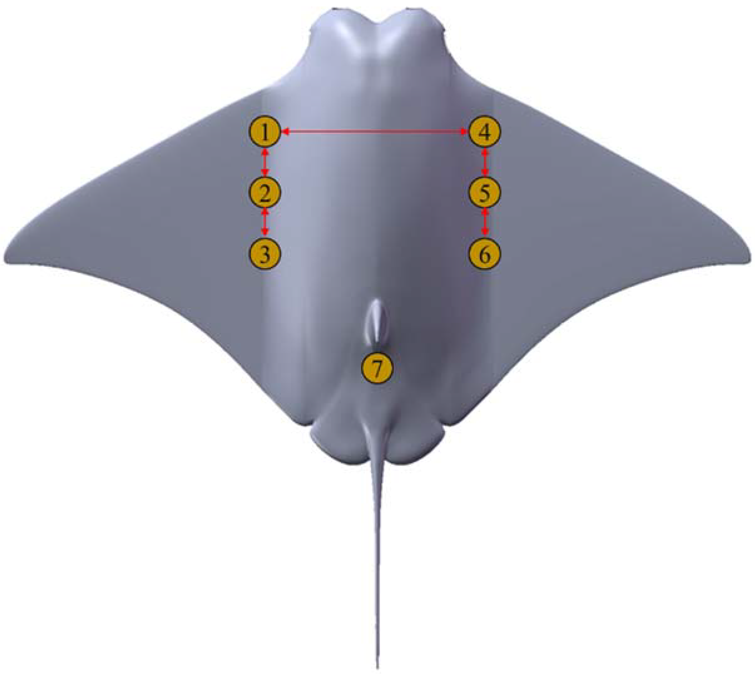
First, determine the pectoral fin coordinate system and select feature points, as shown in
Figure 1. The symmetrical center of the manta ray’s head is the origin O in the coordinate system, and the spread direction of the pectoral fin is the X-axis. The Y-axis is the chord direction of the body, and the Z-axis is perpendicular to the plane of the torso according to the right-hand rule. Since the manta ray has a radiating pectoral fin cartilage structure, we perform kinematic analysis on the selected characteristic points: the tip A
1, the midpoint of the trailing edge A
2, and the root of the trailing edge A
3.
The manta ray’s flapping forward swimming posture is mainly through the pectoral fin flapping to obtain thrust and lift. In the flapping process, the force direction of pectoral fins is opposite to the flapping direction. The frame of pectoral fin chordal motion is shown in
Figure 2a through software processing the video of a manta ray’s forward swimming. As the manta swims forward, the wave created at the base of the leading edge of the pectoral fin simultaneously propagates along the spreading chord. During the whole flapping process, the movement of the posterior edge of the pectoral fin always lags behind the leading edge, and there is a phase difference in the movement of the front and back edges of the pectoral fin. Only when the pectoral fin flapping reaches the limit position, the front and back edges of the pectoral fin are at the same level height. The up-and-down flapping amplitude of the pectoral fin also has an obvious difference, and the maximum amplitude of the upbeat is much larger than that of the downbeat, which is called spatial asymmetry in this paper. The angle of attack generated by chord deformation is the main reason for the thrust generated during the deformation of the manta ray’s pectoral fin. Due to the guiding effect of the chordal traveling wave, the vortex structure in the wake field is smoother and more continuous. Hence, the energy consumption is lower, which is the reason why the pectoral fin flapping with the chordal traveling wave generates greater thrust.
Based on the collected video, we analyzed the chordal motion characteristics of a manta ray’s pectoral fin and selected three typical pectoral fin feature points for kinematic analysis. We found that the chordal displacement of the feature point had the greatest effect on the displacement of the Z-axis, while the displacement of the Y-axis was almost unaffected.
Figure 2b shows the movement of the manta ray’s pectoral fin.
The upward flapping amplitude of the
ith feature point on the pectoral fin of the manta ray is defined as
Rui and the downward amplitude as
Rdi, respectively, representing the vertical distance between the coordinate of the feature point on the pectoral fin at the maximum position of the upward and downward and the straight line between the tail point of the head of the manta ray. By analyzing the motion track of the manta ray’s pectoral fin feature points, it was found that the upward and downward frequencies of each feature point were basically the same during the swimming process before flapping.
Ru1 at the tip of the fin is much larger than
Rd2, while the difference between
Rui and
Rdi gradually decreases as the feature points gradually move toward the tail of the manta ray. It can be concluded that the pectoral fin has a certain amplitude bias during flapping, which reflects the spatial asymmetry of manta ray flapping. There is a certain time difference for each feature point to reach the peak, so it can be considered that there is an obvious phase difference between each feature point. As can be seen from
Figure 2b, the motion of a single feature point is similar to the sine motion. Considering the phase difference between each feature point, in flapping mode, the displacement of manta ray feature points along the Z-axis in the time domain can be expressed as
where
i is the serial number of the feature point;
zi is the Z-axis displacement;
xi is the amplitude bias;
ri is the amplitude;
fi is the frequency;
t is the time; and
ϕi is the initial phase of the feature point
i.
The amplitude bias
xi and the amplitude
ri as a part of the Equation (1) are formulated as follows:
According to the coordinate data of feature points in the literature [
29], the motion of a single feature point is similar to the sine motion. Therefore, based on the flapping forward mode, the displacement equation of manta ray feature points along the Z-axis in the time domain is given
where
Integrated gliding and flapping propulsion is one of the most common movements of manta rays during forward swimming, which has high propulsive efficiency. The string motion sequence of their pectoral fins is illustrated in
Figure 3a. The analysis of the chordal motion sequence of pectoral fins showed that during the integrated gliding and flapping propulsion process, the pectoral fins on both sides of the manta ray initiate the flapping motion. The pectoral fins exhibit chordwise and spanwise wave-propagation characteristics during flapping, enabling the manta ray to generate thrust and lift. During the flapping process, the movement of the posterior edge of the pectoral fin lags behind that of the leading edge. When the manta ray flaps vigorously and rapidly, the displacement of the feature points on the upper and lower Z-axis is roughly equal. After 2 to 3 consecutive flapping cycles, the pectoral fins remain bent upward and enter the glide state. When in the glide state, the pectoral fins do not appear to have any chordal fluctuation but maintain a stable form of upward bending of the pectoral fins on both sides. When the mantas have been in a glide state for a while, then they start shooting down, continuing to flap. Through multiple observations and analyses, it has been found that a direct downward flapping accomplishes the transition from a gliding state to a flapping state. In contrast, the transition from flapping to gliding is typically completed during upward flapping. The above analysis of the manta ray flapping and gliding forward switching mechanism has important guiding significance for the motion control of the manta ray robot, which is conducive to making the manta ray robot’s integrated gliding and flapping propulsion posture closer to the manta ray organism.
Based on the collected video, we analyzed the pectoral fin chordal motion characteristics of integrated gliding and flapping propulsion. We selected three typical characteristic points on the pectoral fin of a manta ray for kinematic analysis. From the side, the chord motion of the characteristic points primarily manifests in the Z-axis displacement, while the variations in Y-axis displacement can be disregarded. The motion trajectories of manta ray feature points are illustrated in
Figure 3b.
The analysis of the pectoral fin chord motion sequence found that the manta ray’s upbeat and downbeat frequencies of each feature point were basically the same in integrated gliding and flapping propulsion. Ru1 ≈ Rd2, Rdi > Rui at the tip of the tail fin, and the difference increases gradually as the feature points move towards the tail fin. It can be considered that there is a certain amplitude deviation in the flapping of manta ray pectoral fins, which is referred to as spatial asymmetry in this study. Each characteristic point has a certain time difference to reach its peak value, indicating a noticeable phase difference among the characteristic points.
In the gliding state, the amplitude bias of the feature points A
1, A
2, and A
3 is basically equal to the upswing amplitude. Therefore, based on the flapping forward mode, the displacement equation of manta ray feature points along the Z-axis in the time domain is given
where
By mathematical approximation the motion trajectories of characteristic points A
1, A
2, and A
3 mean the following conclusions can be drawn:
In addition, it can be observed from the track of feature points that the track curve changes smoothly and quickly when manta rays perform flap and glide mode switching, which is difficult for the existing flap and glide switching strategy of the manta ray robot. Therefore, the flap and glide switching strategy must be improved if the integrated gliding and flapping propulsion mode is to be similar to real manta rays. It is necessary to find a gliding and flapping mode switching strategy suitable for a manta ray robot.
In summary, through the study of manta ray kinematic characteristics, we can see that the following applies:
- (1)
In the process of flapping forward, the frequency of the manta ray flapping up and down at each feature point is basically equal;
- (2)
There is a phase difference between the front and back edges of the pectoral fins, and the movement of a single feature point is similar to sine movement;
- (3)
The maximum value of the up-beat is much larger than the maximum value of the down-beat, and the displacement of the feature points of the upbeat and downbeat of the fin tips is basically equal on the Z-axis during the integrated gliding and flapping propulsion. As the feature points gradually move towards the tail of the manta ray, the amplitude of the up-flap is gradually larger than the amplitude of the down-flap, which indicates that the pectorals of the manta ray have a certain amplitude bias during the flap process, with spatial asymmetry.
- (4)
When the manta ray swims before gliding, the flapping frequency significantly decreases, and the phase difference also reduces. The amplitude deviation during the gliding state is approximately equal to the amplitude of the up-flap. The track curve of the feature points changes smoothly and quickly when the manta ray performs the mode switch of gliding and flapping.
2.2. Development of Manta Ray Robot Prototype
Before designing the structure of the manta ray robot, we looked to real manta rays in nature for inspiration. To get as close to the manta as possible in shape, we modify the scaled form of the real manta ray. As shown in
Figure 4, the manta ray robot mainly comprises three parts: main cabin body, pectoral fins, and tail fin. The chord length is 570 mm; the span length is 934 mm; the maximum thickness is 130 mm; the aspect ratio is about 1.63; the overall weight of the prototype is 8.5 kg; and the main body is 3D printed using nylon laser sintering, which has the advantages of low mass and low cost.
The primary power source for the manta ray robot is the pectoral fin structure. In the process of pectoral fin flapping, propulsive waves are transmitted along the chord and propulsive waves are transmitted along spanwise. Spanwise fluctuation is reflected in the moving trajectory of the endpoints of each fin ray as sinusoidal waves; the chordal flux is represented by the phase difference between the sinusoidal waves in the moving trajectories of the endpoints of each fin ray; and a single steering gear drives the different fins, enabling propagation in both directions. This results in a symmetrical forward thrust and upward lift. The forward thrust makes the manta ray robot swim forward, and the upward lift makes the manta ray robot more stable.
According to the pectoral fin structure characteristics of the manta ray robot, the endpoint of each level of pectoral fin rays on the same side is selected as the feature points, represented by A
1, A
2, and A
3 from front to back. To get as close to the manta as possible in shape, the pectoral fin is designed to resemble a real manta ray. Known by the Solidwork model, the ratio between the length from the start of the pectoral fin contour to each feature point and the total length of the outline was calculated, and the values were 0.57, 0.64, and 0.74, respectively. Selecting the feature points corresponding to the pectoral fins of manta rays, as shown in
Figure 5, means that the trajectory coordinate points of manta ray characteristic points moving with time can be represented with a vector
, and the trajectory coordinates of the manta ray robot’s feature points moving with time can be represented with a vector
. The selection of feature points provides a basis for the kinematic posture similarity evaluation method.
4. Optimization Method of Manta Ray Robot Integrated Gliding and Flapping Propulsion
In this section, the motion-optimization method of the manta ray robot is studied based on the particle swarm optimization algorithm, and we obtained an optimization method for CPG control parameters suitable for the manta ray robot using the similarity of the forward-motion mode of the manta ray robot as the optimization criterion.
4.1. Analysis of Pectoral Fin Flapping of Manta Ray Robot
Since the two pectoral fins of the manta ray robot are entirely symmetrical, we only analyzed the flapping motion of one pectoral fin. In the bionic silicone pectoral fin, the spanwise length of the first, second, and third fins are
s1 = 284 mm,
s2 = 214 mm, and
s3 = 159 mm, respectively. Since the flexible deformation of the pectoral fins has little effect on the displacement of the pectoral fins in the Z-axis direction, it is negligible.
Figure 9 shows the flapping height of the pectoral fins and the rotation angle of the steering gear during the flapping process. It can be concluded that the relationship between the displacement
zi of the feature point A
i at the end of the pectoral fins at all levels along the Z-axis, and the output angle
θi of the pectoral fin steering gear at all levels is as follows:
By substituting the output angle
θi from Equation (7) into Equation (9), we get
By setting
in Simulink, the variation curve of
zi with time can be obtained using Equation (11), as shown in
Figure 9c.
4.2. Method for Evaluating Kinematic Posture Similarity
In the process of integrated gliding and flapping propulsion, too low flap frequency will cause the swimming speed of the manta ray robot to slow down, and reduce the swimming stability. Therefore, in the integrated gliding and flapping propulsion optimization experiment, set the flapping frequency of the experimental prototype at 0.6 Hz to ensure that the manta ray robot had a fast speed and stable posture before entering the gliding and flapping mode.
Based on the above settings, the time normalization process is carried out on the motion trajectories of the feature points. Even if the pectoral fin flapping frequency is not strictly similar to that of the manta ray, the manta ray robot can still calculate the motion similarity by comparing the motion trajectories of the feature points.
Ensure that the sampling time of
and
meets the following requirements:
where,
and
is the sampling time of
and
, and
and
is the natural frequency of pectoral fin flapping of the manta ray and manta ray robot.
The trajectory curve of the manta ray characteristic points
were collected from the video, and the manta ray robot characteristic points
were collected from the video motion-capture system. Since MSE and error are squared, when there is an outlier with a very large error in the data, the value of MSE will also be tremendous. Absolute error is more robust for outliers than MSE. The absolute error gives the actual error value of the measurement result, and its dimension is the same as the dimension being measured. When correcting the measurement results, the absolute error value should be relied on [
32]. The concept of absolute error is also commonly used in bionics to measure the similarity to a biological prototype. Compared with other evaluation indicators, the absolute error converts the difference between the measured value and the true value into the percentage, which can more intuitively describe the difference between the measured value and the true value. To facilitate the evaluation of the similarity between the manta ray robot and the displacement curve of the movement track of the manta ray’s feature points along the Z-axis, the concept of absolute error is introduced:
where
is the difference between the trajectory curves of the manta ray robot and manta ray characteristic points moving over time.
The absolute error definition diagram is shown in
Figure 10:
We utilized absolute error to quantify the differences between the motion trajectories of the characteristic points of the manta ray robot and the manta ray. This allowed us to assess the similarity of motion postures between the manta ray robot and the manta ray:
The similarity of motion postures between the manta ray robot and the manta ray can be expressed as follows [
18]:
The similarity evaluation method can be used to measure the swimming similarity of the manta ray robot in different states, and its similarity value changes with the change of swimming posture. The similarity value is constant if the same swimming posture is adopted at different times.
4.3. Forward Swimming Motion-Optimization Method
Parameter optimization plays a vital role in biomimetic control based on CPG. Currently, researchers generally employ a combination of experimental and simulation approaches to set CPG control parameters. However, the process is relatively complex and inefficient regarding parameter configuration. Therefore, how to adjust the CPG control parameters to move the bionic robot fish closer to the actual fish is still a problem to be solved. The extraordinary motion ability of organisms is of great significance to the motion control of bionic robots. Based on the kinematic posture similarity evaluation method, this study takes the particle swarm optimization algorithm as the optimization goal to improve the similarity of the swimming posture of the manta ray robot and realizes the improvement of the swimming posture similarity and swimming performance.
Particle Swarm Optimization (PSO) [
33] is a global optimization algorithm based on swarm intelligence theory developed by simulating the foraging behavior of birds. Compared with other intelligent optimization algorithms, PSO has the advantages of simple parameters, simple calculation, and fast convergence. In PSO, the solution to each optimization problem is assumed to be a bird in the search space, which we call a “particle”. All particles have an adaptation value determined by the function being optimized. This way, the particles have a defined velocity, direction, and flying distance. The particles then follow the current optimal particle to search the solution space. When solving optimization problems, the algorithm takes the parameters needed to be optimized as particles; each particle has its own position and speed. The position coordinate of each particle is
; the flight speed of each particle is
; and each particle has a fitness value determined using the optimization objective function. For the
ith particle, the historical best position it passes through is denoted as the individual extreme value
; the best position found by all particles in the whole group so far is represented as
. Each particle remembers and follows the current optimal particle, iterating in the solution space to find the optimal value. The iterative process is not entirely random. If a better solution is found, the next better solution is found based on that solution:
where
k is the current iteration number of the PSO algorithm,
, and
K is the maximum iteration number.
represents the velocity of particle
i of dimension
j in the
kth iteration,
.
is the inertia weight coefficient; the size of
represents how much the particle inherits to the current velocity, and will affect the global and local search ability of the particle. The value range is usually [0.4, 0.9].
represents the position of particle
i of dimension
j in the
kth iteration,
.
is the self-learning factor;
is the social learning factor; and its value will affect the particle’s ability to acquire information, usually it is
.
is a random number in the range of [0, 1]. Velocity renewal Formula (18) includes three parts: velocity inheritance of the previous generation
, individual cognition
, and social cognition
. When the iteration meets the termination condition, the output value of the PSO algorithm is the optimal control parameter [
22].
Figure 11 shows the optimization flow diagram of the PSO algorithm.
Since the motion-optimization experiment of the manta ray robot in this paper is carried out in a comprehensive pool, the optimization algorithm requires fast convergence speed and simple calculation, which is precisely the advantage of the PSO algorithm [
20]. Therefore, this paper constructs the CPG control-parameter-optimization method based on the PSO algorithm [
27].
This study intends to adopt the optimization method used in swimming tests, obtain the real-time swimming posture information of the experimental prototype through the motion-capture system, and feed the motion data of the experimental prototype to the optimization algorithm. In a limited pool environment, load the parameter combination calculated by the optimization algorithm into the lower computer and use the set of parameters to move and measure the fitness value of the parameter operation. The fitness value is used to evaluate the result, and the value is fed back to the optimization algorithm. Then, the next set of parameters is generated to continue the swimming experiment.
This paper uses the kinematic relationship between the manta ray and the manta ray robot to evaluate the similarity of the manta ray robot’s integrated gliding and flapping propulsion posture. On this basis, the fitness function is established as follows:
6. Conclusions and Future Work
This study investigated the biological structure and motion characteristics of real manta rays to optimize the motion control of manta ray robots. It has the CPG topology network and prototype based on a manta ray robot and biomimetic control. Additionally, we established an evaluation method for biomimetic motion similarity based on the absolute error of pectoral fin characteristic points and designed an optimization method for CPG control parameters. Using a motion capture system, we conducted online optimization experiments for CPG control parameters. To optimize the motion control of the manta ray robot, the integrated gliding and flapping propulsion experiment was carried out to verify the effectiveness of the motion control based on the CPG network. Secondly, the forward swimming mode of the manta ray robot is optimized online. Under experimental conditions, the similarity between the forward swimming mode of the optimized robot and that of the manta ray is 86.93%, and the forward swimming stability is improved. Compared with manually set CPG control parameters, the motion modal similarity is greatly enhanced, which verifies the effectiveness of the motion-optimization method based on similarity.
In addition to forward swimming, the common motion modes of manta rays include turning, dynamic pitching, and other high-maneuvering motion modes. Turning depends on the asymmetric amplitude and phase difference of pectoral fins on both sides of manta rays, and dynamic pitching depends on the movement of manta rays’ tail fins. However, the similarity-evaluation method established in this paper only relies on the kinematic data collection of unilateral pectoral fins. It is only suitable for the forward motion mode with symmetrical movement of both pectoral fins.
In the future, we plan to expand further the collected motion-data types based on the similarity-evaluation method; optimize the high-mobility motion modes such as turning and dynamic pitching; analyze the influence of bionic motion-control parameters on the motion performance of the manta ray robot; lay the foundation for the autonomous swimming of the manta ray robot; and improve the environmental affinity of the manta ray robot.


 and
and 


