Article

Dynamic Analysis of Full-Circle Swinging Hoisting Operation of a Large Revolving Offshore Crane Vessel under Different Wave Directions

1
Ship and Maritime College, Guangdong Ocean University, Zhanjiang 524088, China
2
Ocean College, Zhejiang University, Zhoushan 316021, China
3
Faculty of Maritime and Transportation, Ningbo University, Ningbo 315211, China
4
School of Electronics and Information Engineering, Guangdong Ocean University, Zhanjiang 316021, China
*
Author to whom correspondence should be addressed.
J. Mar. Sci. Eng. 2023, 11(1), 197; https://doi.org/10.3390/jmse11010197
Submission received: 15 November 2022 / Revised: 24 December 2022 / Accepted: 9 January 2023 / Published: 12 January 2023
(This article belongs to the Special Issue Hydrodynamics of Offshore Structures)

Abstract

:
Waves have an important influence on the motion performances of offshore crane vessels. The floating crane vessel in waves gives rise to the motion of the lifted object which is connected to the hoisting wire. Based on the geometric parameters of a revolving offshore crane vessel, combined with the specific process of the floating crane vessel at work, a model of the offshore crane vessel under full-circle swing hoisting has been established by OrcaFlex. With the change in wave direction, the dynamic response of the system is made and the impact force between the support vessel and the hanging object and the tension of the crane wire under different wave directions is obtained. At the same time, the minimum impact forces between the support vessel and the hanging object and the tension of the crane wire and their wave directions are obtained. According to the calculated result, the optimal design of the full-circle swing hoisting operation of large revolving offshore crane vessel has been determined.

1. Introduction

Along with social progress and the wide range of human activities, production capacity is growing, and a consequent problem is the consumption of a large number of resources [1]. It has been difficult for land-based resources and space to meet the needs of social development and countries around the world have increasingly been paying greater attention to the exploitation of offshore resources [2]. The demand for offshore facilities, such as underwater transportation systems for oil and gas fields or wind parks, is increasing. Offshore oil and gas fields will be developed to a large extent, and all processing equipment will be on the seabed. Therefore, the operability of underwater construction is urgently needed. Offshore crane vessels are employed for a variety of tasks in offshore areas, such as transportation, assembling of costly structures, and salvage operations. Offshore cranes are also widely used to transfer cargo from one vessel to another, or from one vessel to the land. Efficient and safe operations of offshore crane vessels at offshore locations are thus becoming increasingly important due to the increase in offshore activities, particularly in deep water regions, and with a demand for higher lift capacity [3,4,5].
There exists a considerable amount of literature devoted to the analysis and control of the offshore crane operations [6,7,8,9,10,11]. For example, Spathopoulos and Fragopoulos [12] studied the modelling of a crane for offshore lifting operations and proposed an anti-pendulation arm. The crane vessel is always a rigid–flexible coupling multibody system, which can affect the accuracy of dynamic analysis. He et al. [13] proposed a dynamics analysis model of an offshore crane vessel based on rigid–flexible coupling virtual prototyping. Fang et al. [14] proposed a dynamics analysis model of an offshore crane vessel consisting of the boom and a payload by employing the Lagrange method, with specific emphasis on the effect of the vessel’s motion on the payload swing. Offshore crane vessels are greatly impacted by the marine environment. Chu et al. [15] introduced a modelling approach for offshore crane operations based on the bond graph method to tackle the problems of sea load challenges. Previous studies have provided strong references for the further dynamic behavior exploration of the offshore crane vessels under various working conditions [16,17,18].
Offshore crane vessels are permanently faced with fluctuations and external loads caused by the ship’s own motion, waves, and wind [19]. These affect their normal work. Many studies have been carried out on the dynamic analysis of offshore crane vessels under complex environmental loads. The wave-induced motion of the large floating crane vessel coupled with the motion of the hanging object will generate complex nonlinear motion of the multi-body system [20,21,22,23,24]. Than et al. [25] simulated the dynamic behavior of a real crane in the marine environment using a general non-linear dynamic analysis program for flexible multibody systems. The numerical simulation of offshore cranes performing sealift operations was carried out. Hannan and Bai [26] numerically investigated the nonlinear dynamic responses of a fully submerged payload hanging from a fixed crane vessel. They considered the different orientations of the crane vessel and submerged payload and revealed the dynamic behavior of the submerged payload of an offshore crane vessel during operations. The results showed that the change in wave motion frequency significantly changed the motion behavior of the load and produced various nonlinear phenomena. Ye et al. [27] studied the estimation of low-frequency crane force in the horizontal direction during the loading and unloading phase of offshore crane vessel operation under various environmental conditions. They introduced a new time-varying mooring stiffness term into the nonlinear passive observer of the offshore crane vessel and used it in the joint parameter state estimator to estimate the force of the horizontal crane and the state of the offshore crane vessel. In waves, the offshore crane vessel gives rise to the motion of the lifted object that is connected to the hoisting cable. In return, the dynamic tension induced by the lifted object also affects the motion responses of the offshore crane vessel. Zhao et al. [28] studied the dynamic responses of three offshore crane vessels through fully coupled time domain simulations. The motions of the vessel, the crane tip, the installed blade and the blade root, and tension in tugger lines were investigated. The results showed that offshore sites with short wave conditions had higher feasibility in floating vessel installation than at sites with long wave conditions. Farhan et al. [29] carried out an experimental study and numerical analysis of crane operability on a catamaran-hulled crane vessel. It was found that the response spectra of the results of numerical analysis and experimentation had various differences depending on the observed mode of motion. Landsverk et al. [30] investigated the coupled dynamics between a multipurpose crane with payload, and an offshore carrying vessel.
As can be seen from a brief review of the most advanced research, the current research mainly focuses on the modeling and analysis of the couped dynamic responses between the crane and vessel under complex environmental conditions, during which the vessel only carries out several simple operations, such as lifting and lowering. There are few studies on the dynamic analysis of a full-circle swinging hoisting operation of offshore crane vessel under complex environmental conditions. Therefore, it is necessary to study the hydrodynamic response of this complex operation. In this paper, the lumped mass method and the time-domain coupled dynamic analysis method are used to simulate the full-circle swinging hoisting operation of a large revolving floating crane vessel. The dynamic model is established, and the hydrodynamic response under different wave directions is studied using OrcaFlex. In order to ensure maximum simulation authenticity, the cycle simulation time step must be shorter than the shortest natural nodal period and should not exceed the model of the shortest natural cycle period 1/10. Based on the hydrodynamic performance calculation results of the system, some guidance advice has been given. The remainder of this paper is organized as follows. Section 2 introduces the lumped mass method and the dynamic theory of the swinging hoisting operation of an offshore crane vessel. Section 3 introduces the numerical model. Section 4 presents the results and discussion. Finally, the conclusions drawn from this paper are presented in Section 5.

2. Methodology

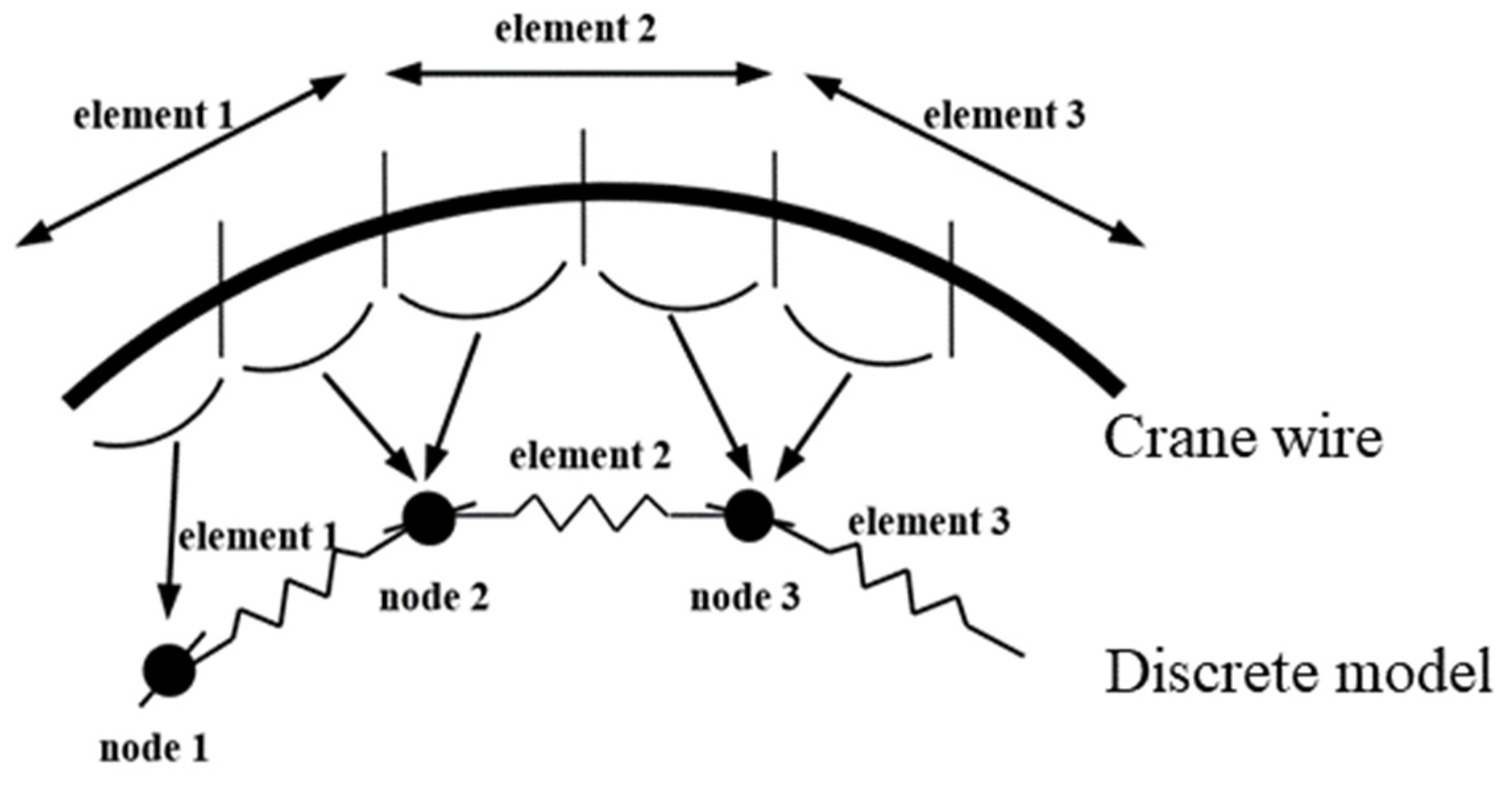
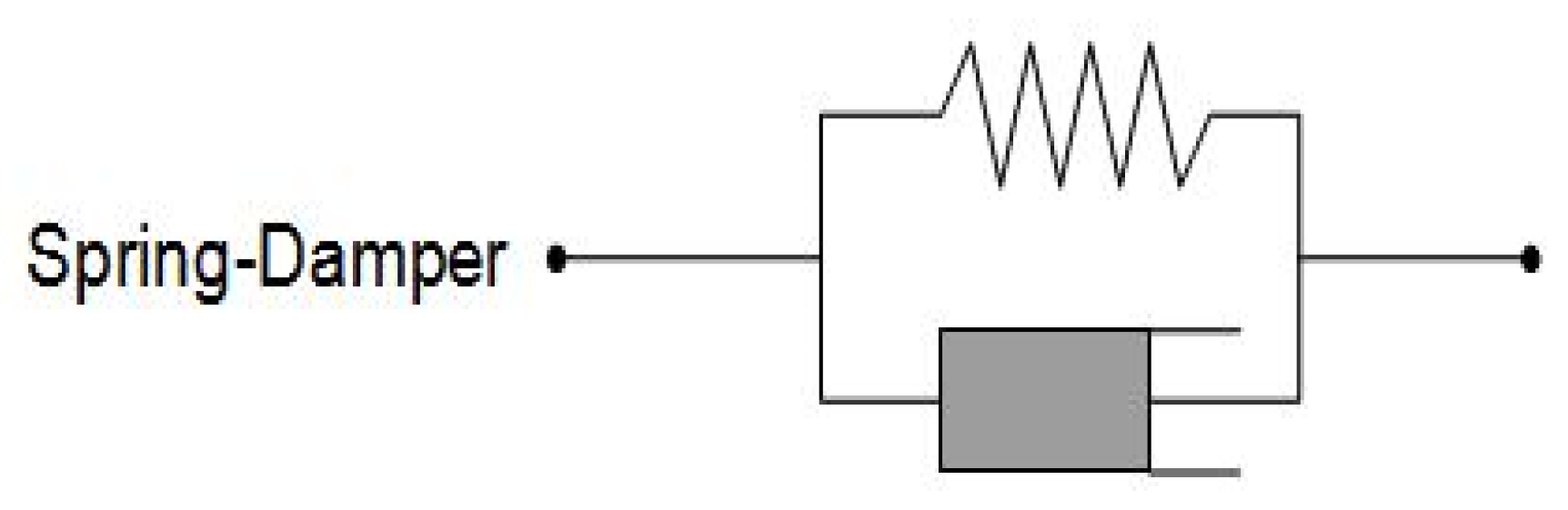
2.1. The lumped Mass Method

The crane wire model was considered as a slender, flexible cylindrical cable. The discrete lumped mass model was used to solve the nonlinear boundary value problem. The basic idea of this model is to divide the towed cable into N segments, and the mass of each element is concentrated on one node, so that there are N+1 nodes. The tension T and shear V acting at the ends of each segment can be concentrated on a node, and any external hydrodynamic load is concentrated on the node. The equation of motion of the i-th node (i = 0, 1 … N) is:
M A i R ¨ i = T e i T e i 1 + F d I i + V i V i 1 + w i Δ s - i
Among them, R represents the node position of the cable.
M A i = Δ s - i ( m i + π 4 D i 2 ( C a n 1 ) ) I Δ s - i π 4 D i 2 ( C a n 1 ) ( τ i τ i 1 ) is the mass matrix of a node, I is the 3 × 3 identity matrix, T e i = E A ε i = E A Δ s 0 i Δ s ε i represents effective tension at a certain node, Δ s 0 i = L 0 ( N 1 ) represents the original length of each segment, Δ s ε i = | R i + 1 R i | represents the stretched length of each segment, EA represents the axial stiffness of the wire.
F d I i represents the external hydrodynamics of each node, which is calculated according to the Morison equation:
F d I i = 1 2 ρ D i 1 + ε i Δ s - i ( C d n i | v n i | v n i + π C d t i | v t i | v t i ) + π 4 D i 2 ρ C a n i Δ s - i ( a w i ( a w i · τ i ) ) τ i
where ρ is the density of sea water, Di is the diameter of each cable, Cdni is the normal drag coefficient, Cdti is the tangential drag coefficient, Cani is the inertia coefficient. Figure 1 depicts the lumped mass model.

2.2. Dynamic Theory of Swinging Hoisting Operation

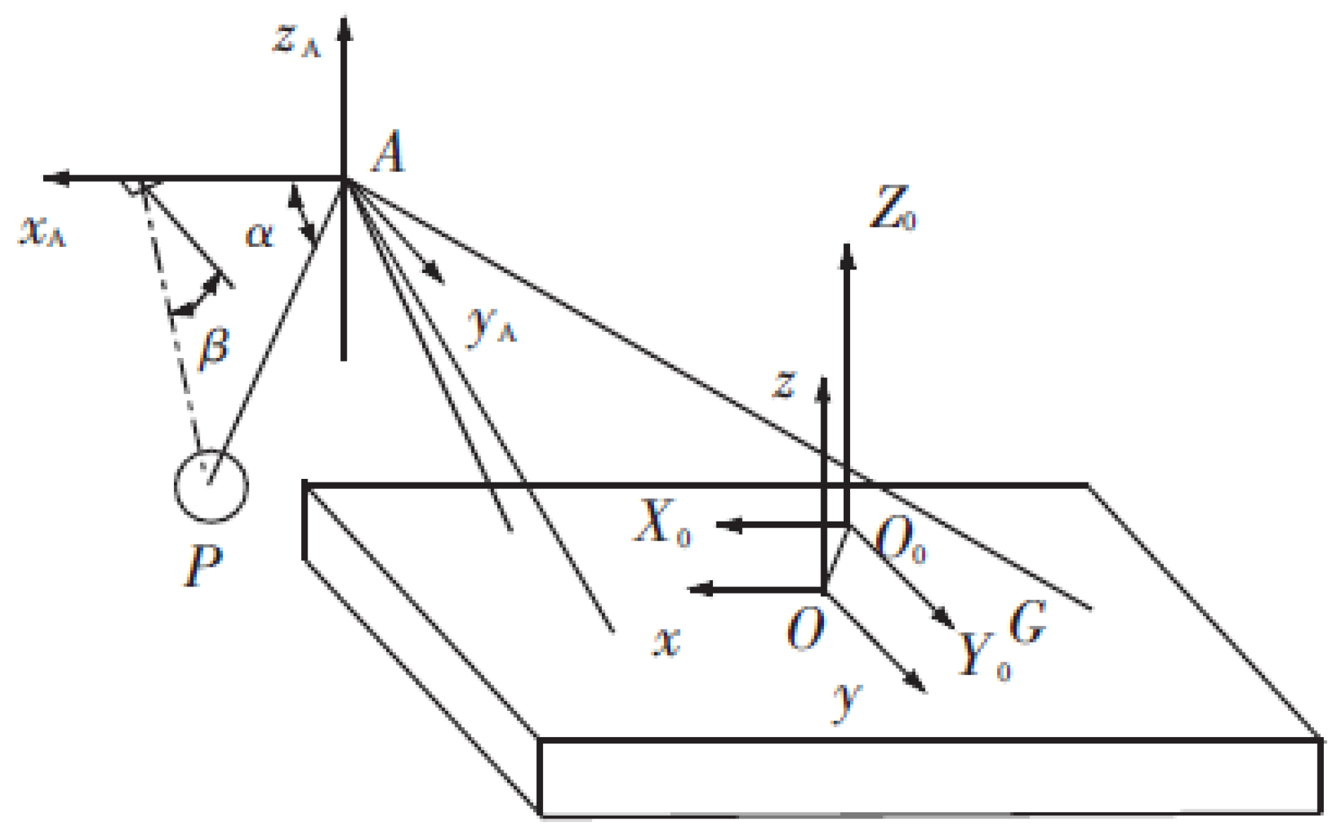
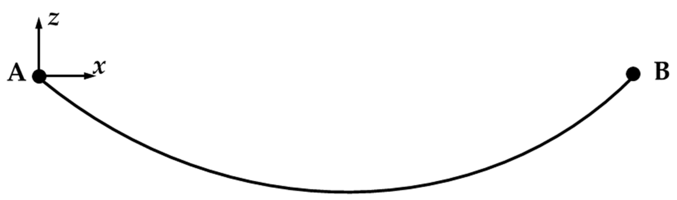
2.2.1. Coordinate System

The coordinate systems of the full-circle swinging hoisting operation of a large revolving offshore crane vessel are shown in Figure 2. There are two coordinate systems, the fixed coordinate system O0x0y0z0 and the vessel coordinate system Oxyz. In Figure 2, point A is the endpoint of the boom, point P is the simplified particle of the hoisted object, α and β represent the out-of-plane swing angle and in-plane swing angle, respectively.

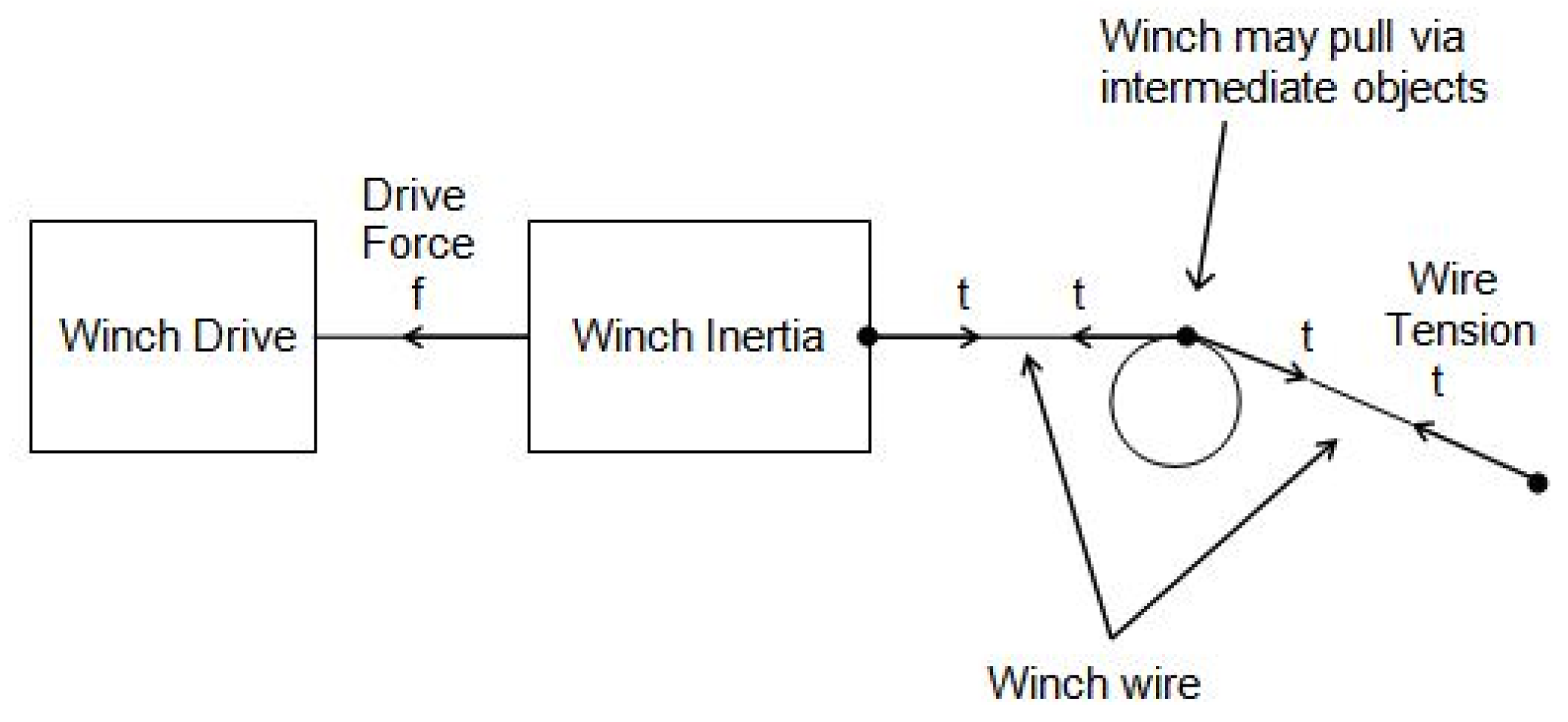
2.2.2. Motion Equation of the Suspension Crane Wire

Since the elongation and bending torsional stiffness of the crane wire of the swinging hoisting system are very small, this paper will not consider them, temporarily. When the suspension crane wire is under tension, it can be approximately regarded as an elastic rod, so the suspension crane wire is discretized into a mass spring model, and its tension is obtained based on the lumped mass method:
F = i i + 1 E i A i ε i ( i = 1 , 2 , 3 , )
where F is the tension of the crane wire, kN; Ei is the elastic modulus of a selected section of suspension crane wire, N/m2; Ai is the cross-sectional area of a selected section of suspension crane wire, m2; εi is the dimensionless longitudinal strain.
The effective tension of the suspension crane wire is as follows:
F ˜ = F i + F p
where F ˜ is the effective tension of the suspension crane wire under the consideration of hydrodynamic force, kN; Fi is the tension of the crane wire, kN; Fp is the hydrostatic pressure acting on the crane wire in a stepped manner, kN. The hydrodynamic force can be calculated by the Morison equation, as shown in Equation (2).
The motion equation of the suspension crane wire is as follows:
ρ r ¨ + C A ρ w r ¨ n + ( E I r ) ( λ r ) = w + F d
λ = F + F p E I k 2
where ρ is the density of suspension crane wire, kg/m; ρw is seawater density, kg/m3; EI stands for bending stiffness, kN·m2; r ¨ is the acceleration of the crane wire, m/s2; r is the displacement of the crane wire, m; w is the effective mass, kg; k is the curvature, rad/m. The apostrophe of the superscript indicates derivation.
X (z, t) represents the vertical displacement of the crane wire (measurement unit: m), where t represents time (measurement unit: s), and z represents the vertical position of one end of the crane wire connecting the hoisted object (measurement unit: m). For the convenience of expression, the tangential drag force of the crane wire is not considered, temporarily, so the vertical motion equation when the crane wire is tensioned is:
E A i 2 X ( z , t ) z 2 + g ( ρ ρ w ) A i = m 2 X ( z , t ) t 2
where E is the elastic modulus, kN/m2; g is the acceleration of gravity, m/s2, taken as 9.8; m is the mass per unit length, kg/m.
v 2 = E A i / m
K = g ( ρ ρ W ) A i / m
Equation (9) can be obtained by substituting Equations (8) and (9) into (7).
v 2 2 X ( z , t ) z 2 + K = 2 X ( z , t ) t 2
The motion equation of the vessel is as follows:
x = R a cos ( ω t φ )
where, v represents the speed of sound propagation in the crane wire, m/s; X represents the displacement of the vessel (including 6 degrees of freedom). The unit of measurement for translation is m, and the unit of measurement for rotation is rad. R is the amplitude operator response of the vessel. The unit of measurement is m for translation and rad for rotation. a is the amplitude of wave, m; ω represents the circular frequency of the wave, Hz. φ is the initial phase angle of the vessel, rad.
The initial value of point A in the hull coordinate system is (xc, yc, zc). The motion equation of point A is as follows.
{ x A 0 y A 0 z A 0 } = [ 1 0 0 0 z A y A 0 1 0 z A 0 x A 0 0 1 y A x A 0 ] { x }
The acceleration equation of point A is as follows.
{ x ¨ A 0 y ¨ A 0 z ¨ A 0 } = [ 1 0 0 0 z A y A 0 1 0 z A 0 x A 0 0 1 y A x A 0 ] { x ¨ }
The coordinates of point A in the fixed coordinate system O0x0y0z0 can be derived from the position relationship between coordinate axes, as shown below.
{ X A Y A Z A } = [ x 0 y 0 z 0 ] + [ x A y A z A ] = [ x 0 y 0 z 0 ] + T [ x 0 y 0 z 0 ]
where, xA0, yA0, zA0 are the initial coordinates of point A, m. xA, yA, zA are the coordinates of point A moving with the vessel in the vessel coordinate system, m. x ¨ A 0 , y ¨ A 0 , z ¨ A 0 represent the accelerations of point A in three directions in the fixed coordinate system, respectively, m/s2. x and x ¨ represent the displacement and acceleration of the vessel, respectively. When the displacement of the vessel is translational, the measurement unit of its displacement is m, and the measurement unit of its acceleration is m/s2. When the displacement of the vessel is rotational, the measurement unit of its displacement is rad, and the measurement unit of its angular acceleration is rad/s. XA, YA, and ZA are the coordinates of point A in the fixed coordinate system, m; x0, y0, and z0 are the initial coordinates of the hull, m. x A , y A , and z A are the velocities of point A in the vessel coordinate system with the ship motion, respectively, m/s; T is the transformation matrix between two coordinate systems.
The coordinates of the hoisted object P are as follows.
[ X P Y P Z P ] = [ X A Y A Z A ] + [ l cos β sin α l sin α l cos β cos α ]
where, XP, YP, and ZP represent the three spatial coordinate values of the hoisted object, m. α and β represent the out-of-plane swing angle and in-plane swing angle, respectively, rad. l represents the total length of the crane wire.
When the hoisted object is lowered, it can be known from Newton’s second law that:
F + G P + F d = m P a
where, GP represents the gravity of the hoisted object, kN. mP is the mass of the hoisted object. a is the acceleration of the hoisted object, m/s2.
The force of the hoisted object is projected to the x, y, and z axes in all directions, and A is the blocked area of the hoisted object, so Equation (15) can be written as:
T m cos β sin α + Δ X X ¨ P + C a X Δ X X ¨ P a X + 1 2 ρ C d X A X V X X · P V X X · P T m sin β + Δ Y X ¨ Y + C a Y Δ Y Y ¨ P a Y + 1 2 ρ C d Y A Y V Y Y · P V Y Y · P T m cos β cos α m P g + Δ Z Z ¨ P + C a Z Δ Z Z ¨ P a Z + 1 2 ρ C d Z A Z V Z Z · P V Z Z · P = m P X ¨ P m P Y ¨ P m P Z ¨ P
where Tm is the tension at one end of the crane wire connecting with the hoisted object, kN. Δ X , Δ Y , and Δ Z are the added mass of attached water in X, Y, and Z directions, kg. X ˙ P , Y ˙ P and Z ˙ P are the velocities of the hoisted object in X, Y, and Z directions, respectively, m/s. X ¨ P , Y ¨ P and Z ¨ P are the accelerations of the hoisted object in X, Y, and Z directions, respectively, m/s2. CaX, CaY, and CaZ are the added mass coefficients of suspension crane wire in X, Y, and Z directions, dimensionless. CdX, CdY, and CdZ are the added drag force coefficients of the suspension crane wire in X, Y, and Z directions, dimensionless. aX, aY, aZ are the accelerations of the hoisted object in X, Y, and Z directions, m/s2. AX, AY, and AZ are the normal area of the hoisted object perpendicular to the X, Y, and Z coordinate axes, m2. VX, VY, and VZ represent the speed of the vessel along X, Y, and Z directions, m/s.
The swing angle of the hoisted object and the effective tension of the crane wire can be obtained by simultaneous Equations (3)–(17).

3. Numerical Model Set-Up

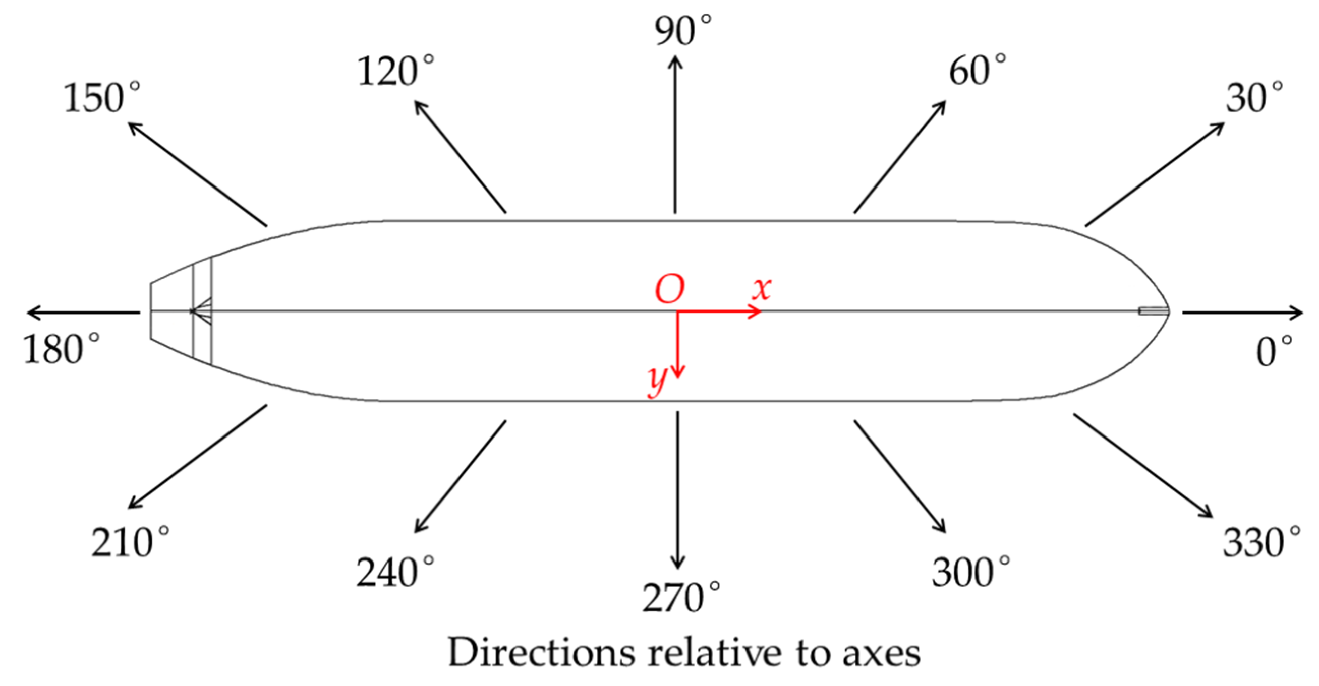
3.1. Basic Parameters of the Vessel and Wave Direction

Each vessel in the model must specify its own RAO in OrcaFlex. The vessel data, displacement RAOs, wave load RAOs, wave drift QTFs, stiffness, added mass, and damping data all came from an NMIWave diffraction analysis of an overall 103-m-long tanker in 400 m of water depth. For the wave drift QTFs, the direct integration and the full QTF matrix were used. The vessel used in this paper had the following properties: beam B = 15.95 m, draft T = 6.66 m, transverse GM = 1.84 m, longitudinal GM = 114 m, block coefficient Cb = 0.804. The diffraction analysis used 8% extra damping in roll about CG [31].
The Airy wave theory was selected. The depth of the water was 100 m. The wave height was fixed at 2.5 m, and the wave period was fixed at 8 s. The definition of the wave directions is shown in Figure 3.

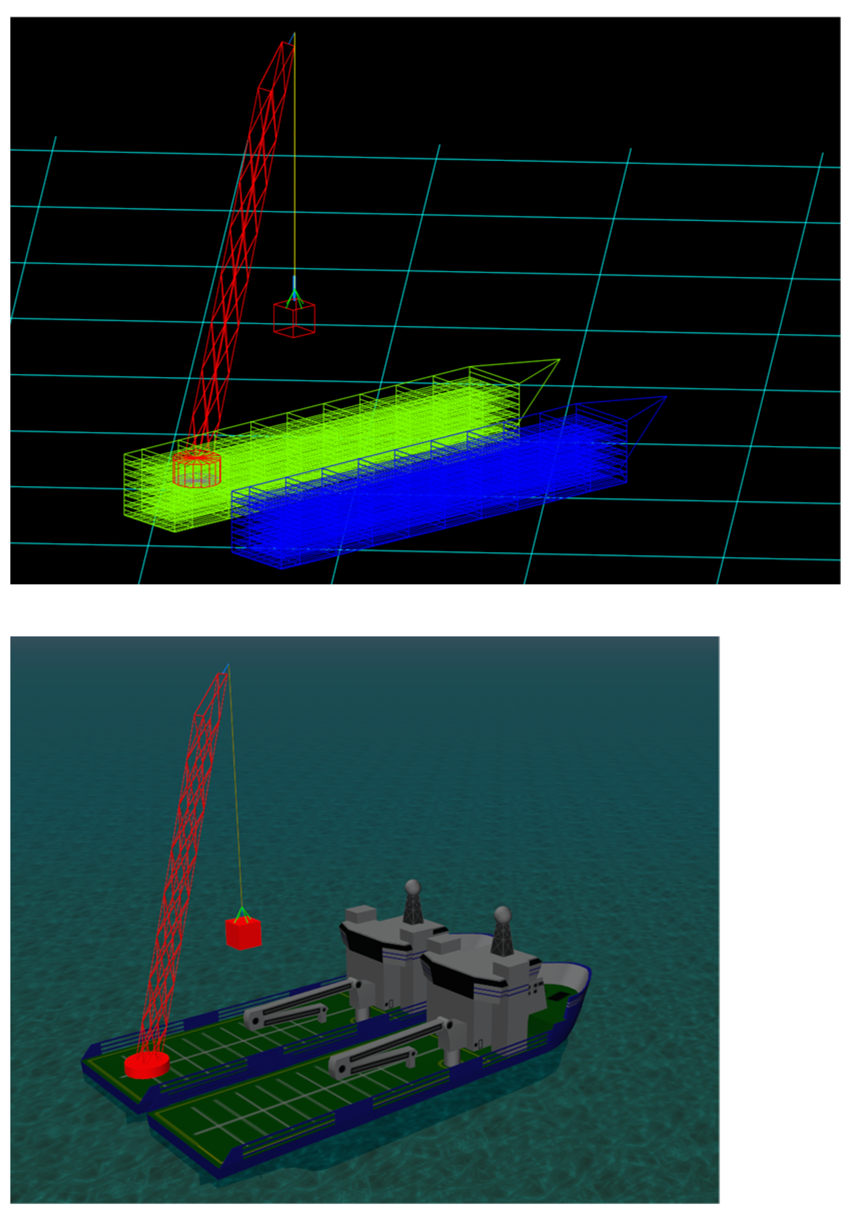
3.2. Numerical Model in OrcaFlex
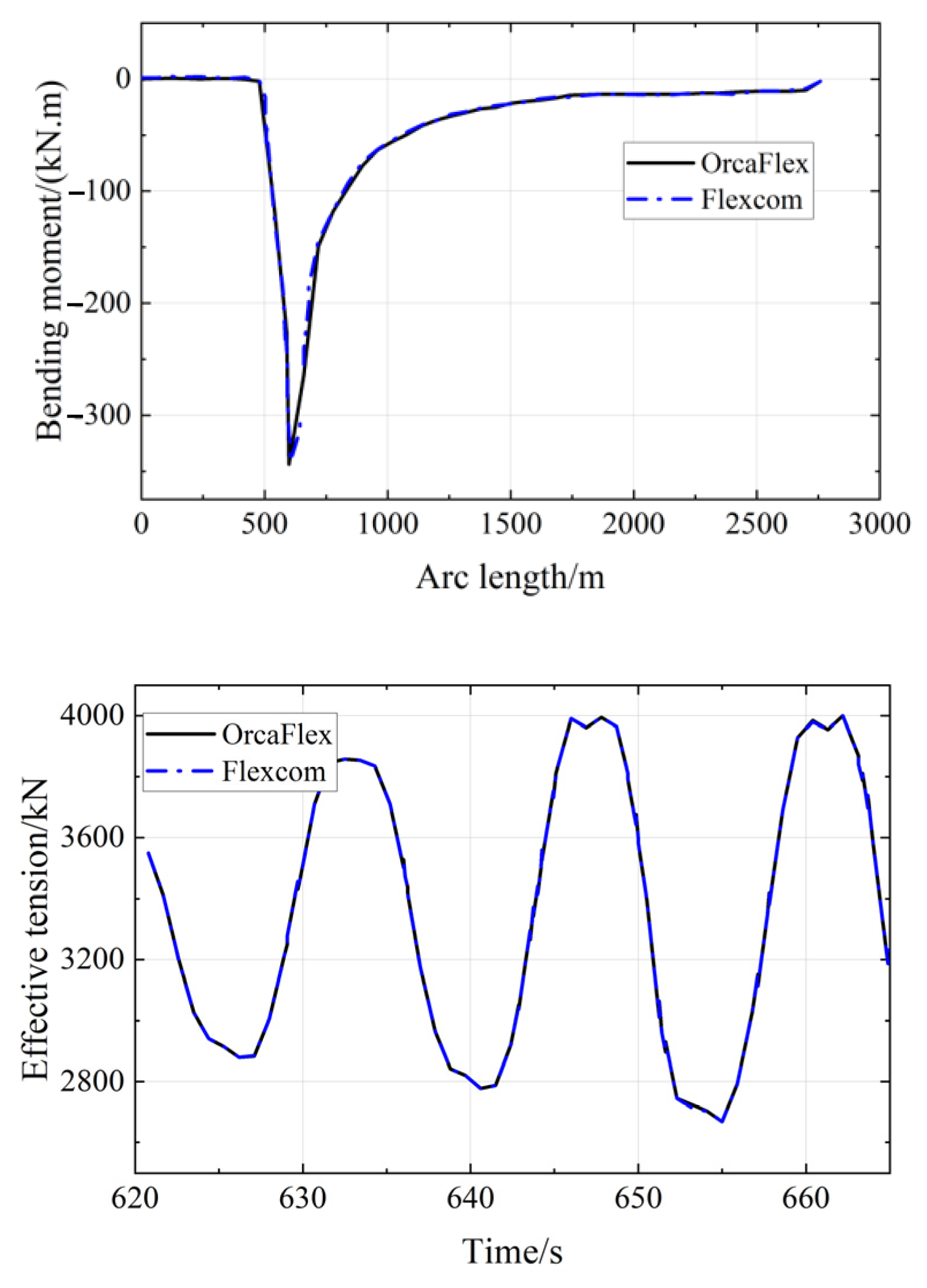
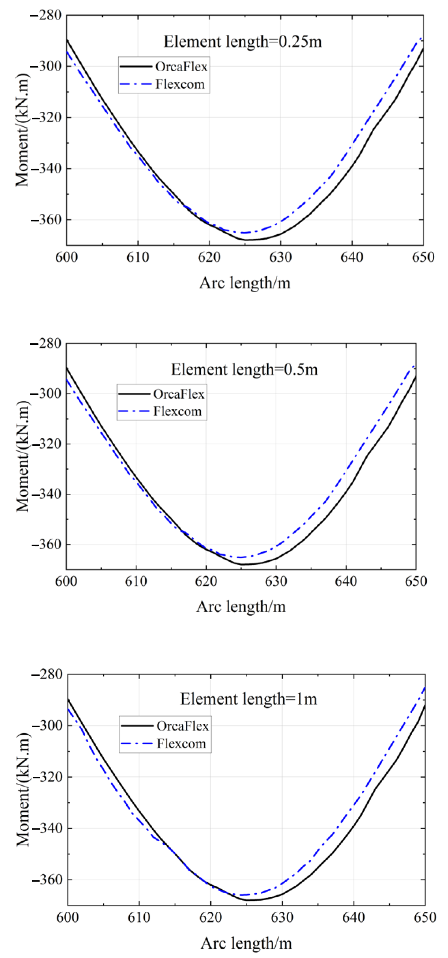
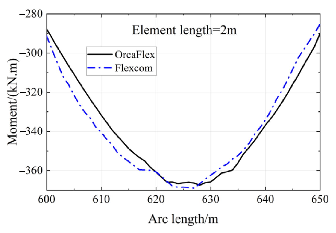
The crane pivot was established by the composition of the winch element and the 6D buoy, the crane arm was built by the 6D buoy, which was regarded as a rigid body. The function of the winch is to make the crane pivot rotate. The length of the crane boom is 90 m, and the mass was 30 t. In order to make the crane boom rotate with the crane pivot at the same time, 4 lines with infinite axial stiffness, bending stiffness, and torsional stiffness were used to fix them together. The vertical decentralization of the hoisted object was realized by adding a winch at the end of the crane wire. Winches provide a way of modelling constant tension or constant speed. They connect two (or more) points in the model by a winch wire, which is fed by the inertia of the winch (usually representing the winch drum) and then driven by the winch drive unit (usually representing the winch hydraulic unit driving the drum). In addition to connecting its two ends, the winch wire can optionally pass through the middle point, in which case it is similar to passing through a small frictionless pulley. The wire tension on either side of the intermediate point is then applied to that point. If the point is offset on the object involved, this will also give rise to an applied moment, just as shown in Figure 4. In order to ensure maximum simulation authenticity, 4 link elements were used to connect the shackle, which was simulated by a 3D buoy. The link element is equivalent to a spring damper, which can take both compression and tension and can have either a linear or a piecewise-linear length–force relationship, as shown in Figure 5. The link element can buffer the impact of the hoisted object during the simulation and ensure the motion performance of the whole system. Then, through the shackle, the link is connected to the winch at the end of the crane wire. The inner diameter of the crane wire was 0 m, the outer diameter was 0.5 m, the bending stiffness EI was 0, the axial stiffness EA was 101,000 KN, the line density was 7.85 t/m3, the Poisson’s ratio υ was 0.293, the length was 57.5 m. Completed in OrcaFlex, the model of the system is shown in Figure 6 [32].

3.3. Validation

Two cases were studied to validate the correctness of OrcaFlex. The first case is the comparison with the finite element software Flexcom [33]. Flexcom and OrcaFlex were used to establish the analysis model for a 12-inch diameter steel catenary riser (SCR) connected to a semi-submersible platform under a water depth of 1800 m. This typical rigid catenary design is used in Gulf of Mexico or West African conditions. The typical limit- and wave-induced fatigue analysis of the model under regular and irregular sea conditions was carried out.
The selected sea state is representative of typical deep-water Gulf of Mexico sea conditions [33]. Therefore, the riser wall was relatively thick. In order to ensure the authenticity of the simulation and ensure the induced flutter of the riser and the seabed instability during the model in-place operation, a large normal seabed stiffness was adopted. The length of the SCR was 2765 m, the diameter of the SCR was 0.308 m, the wall thickness of the SCR was 0.027 m. The riser density was 7.85 t/m3. The fluid density in the riser was 0.8 t/m3. The normal drag coefficient was 0.3. The force coefficient was 1.2. The normal additional mass coefficient was 1. With the exception that the length of the unit section approximately 300 m from the touchdown end was 1 m, the lengths of other unit sections were set as 5 m. Figure 7 shows the comparison results of bending moment and the time history of the effective tension between Flexcom and OrcaFlex. Figure 8 shows the bending moment distribution of different segment lengths along the length direction.
The second case was a calculation of the static rigid catenary depicted in Figure 9. The calculation results were compared with the theoretical results of a classical catenary [34]. The specific calculation parameters were as follows: the catenary length was 120 m, the linear density was 0.02 t/m, the axial stiffness EA was 500 KN, the horizontal distance between A and B was 55 m, and the vertical distance between the two points was 0. On a horizontal line, the segment distance between each two adjacent nodes was taken as 10 m. The comparison of tension of the point A between calculation results and theoretical results is shown in Table 1.
Through calculation and comparison, it was found that there was little difference between the Flexcom results and OrcaFlex results, which indicates that the accuracy and reliability of OrcaFlex and the current popular pipeline calculation software are similar. Compared with the classical catenary theory, the calculation results are also very close, which shows that the results calculated by OrcaFlex are also scientific and reliable. OrcaFlex is a good professional software program for dynamic analysis of offshore risers; therefore, it is scientifically sound and reasonable to use OrcaFlex for modeling and calculation in this paper.

4. Results and Discussion

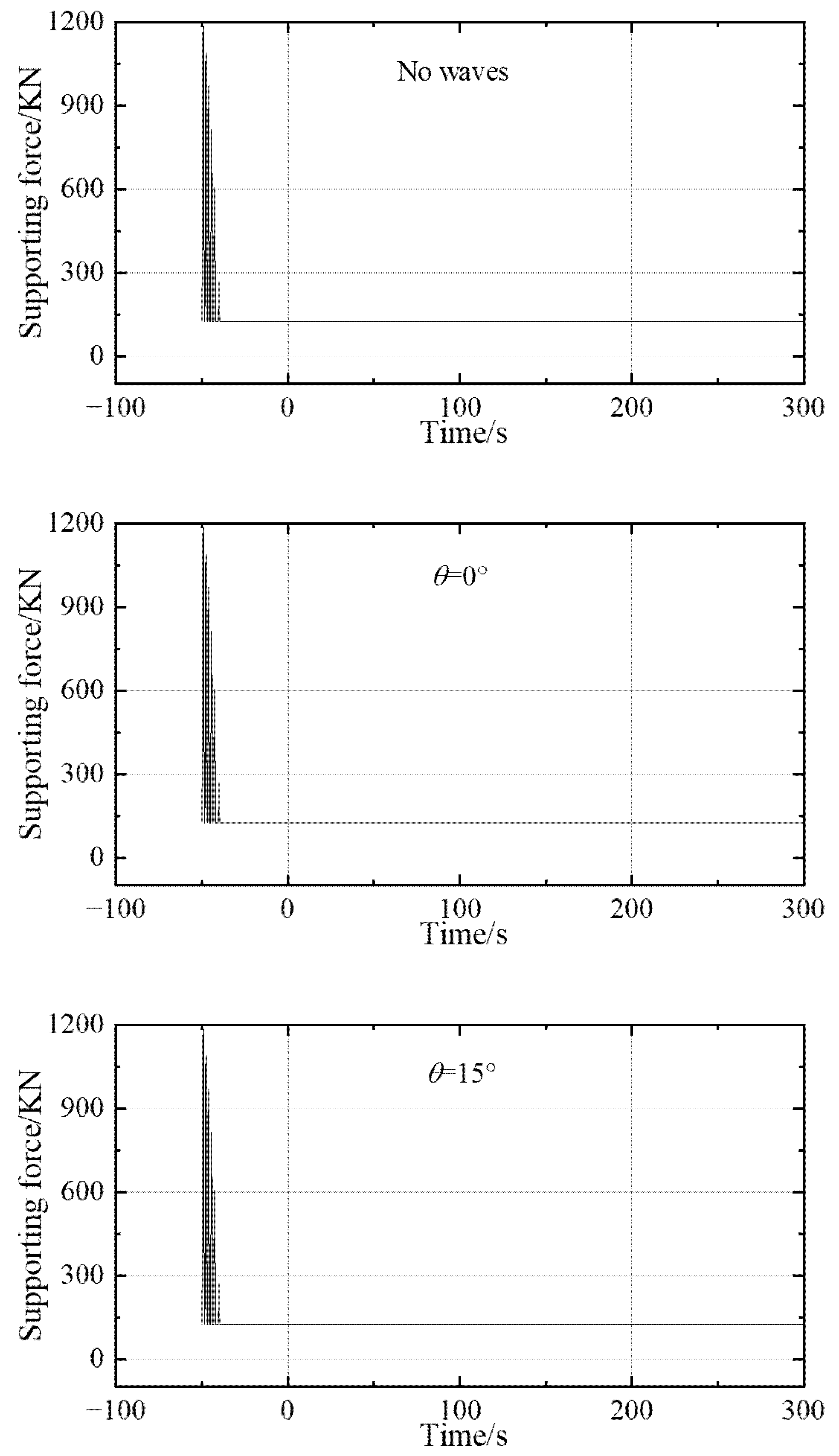
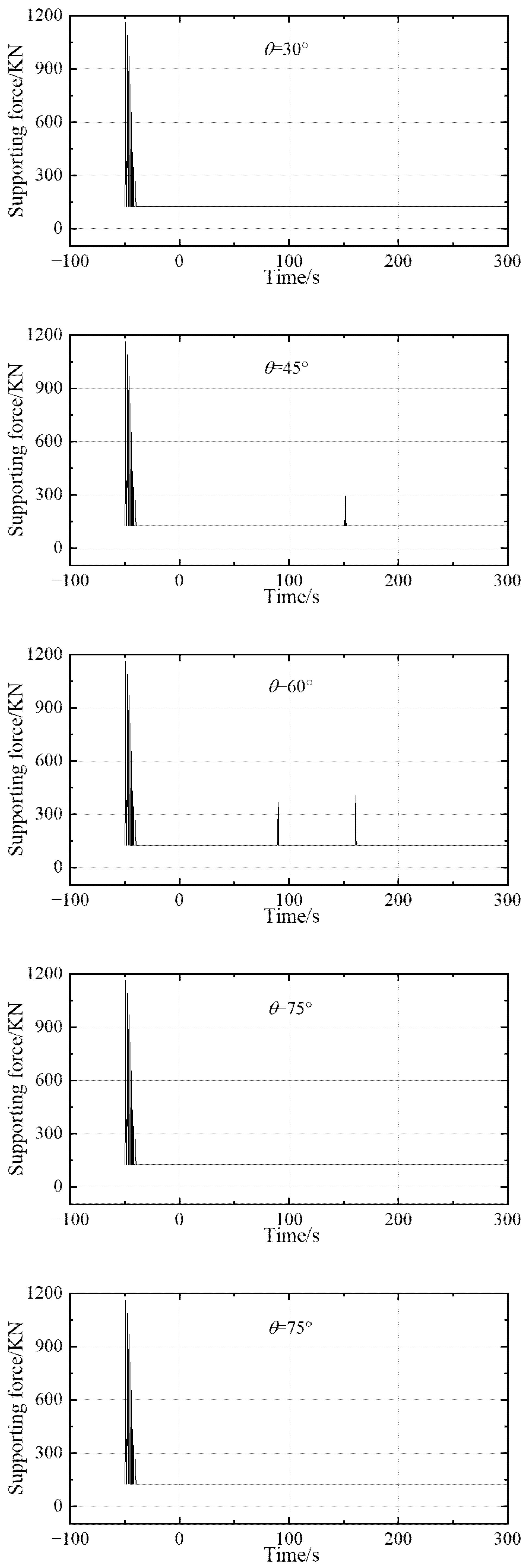
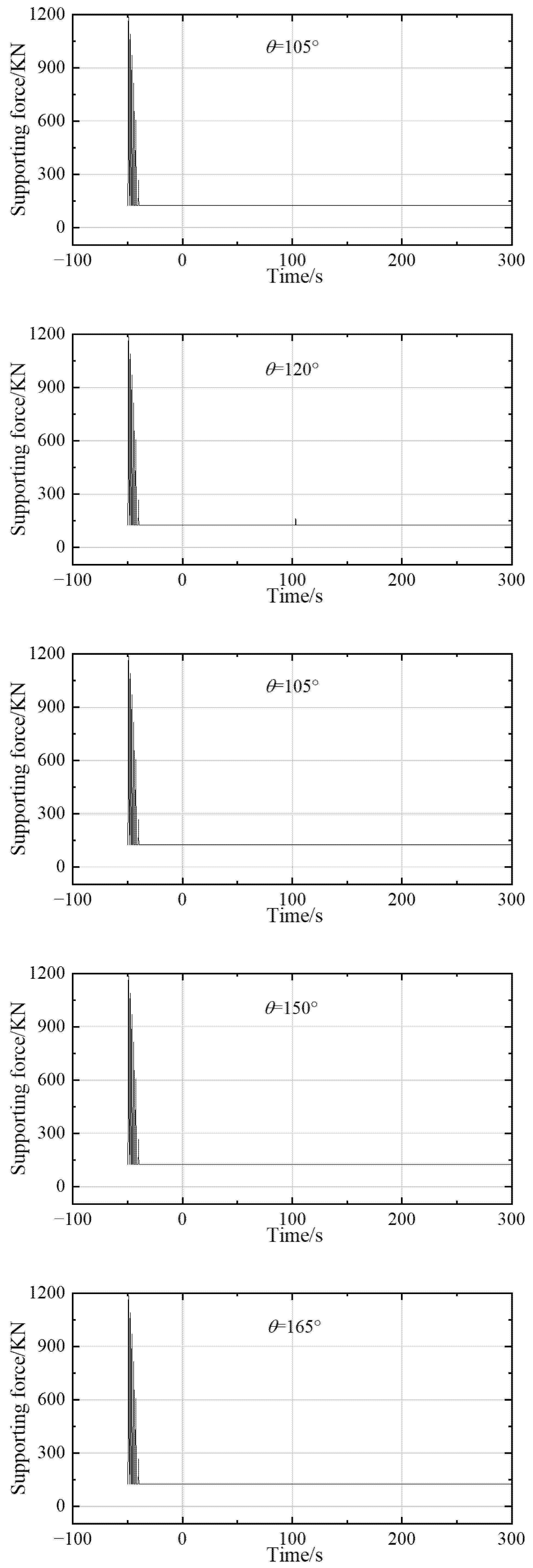
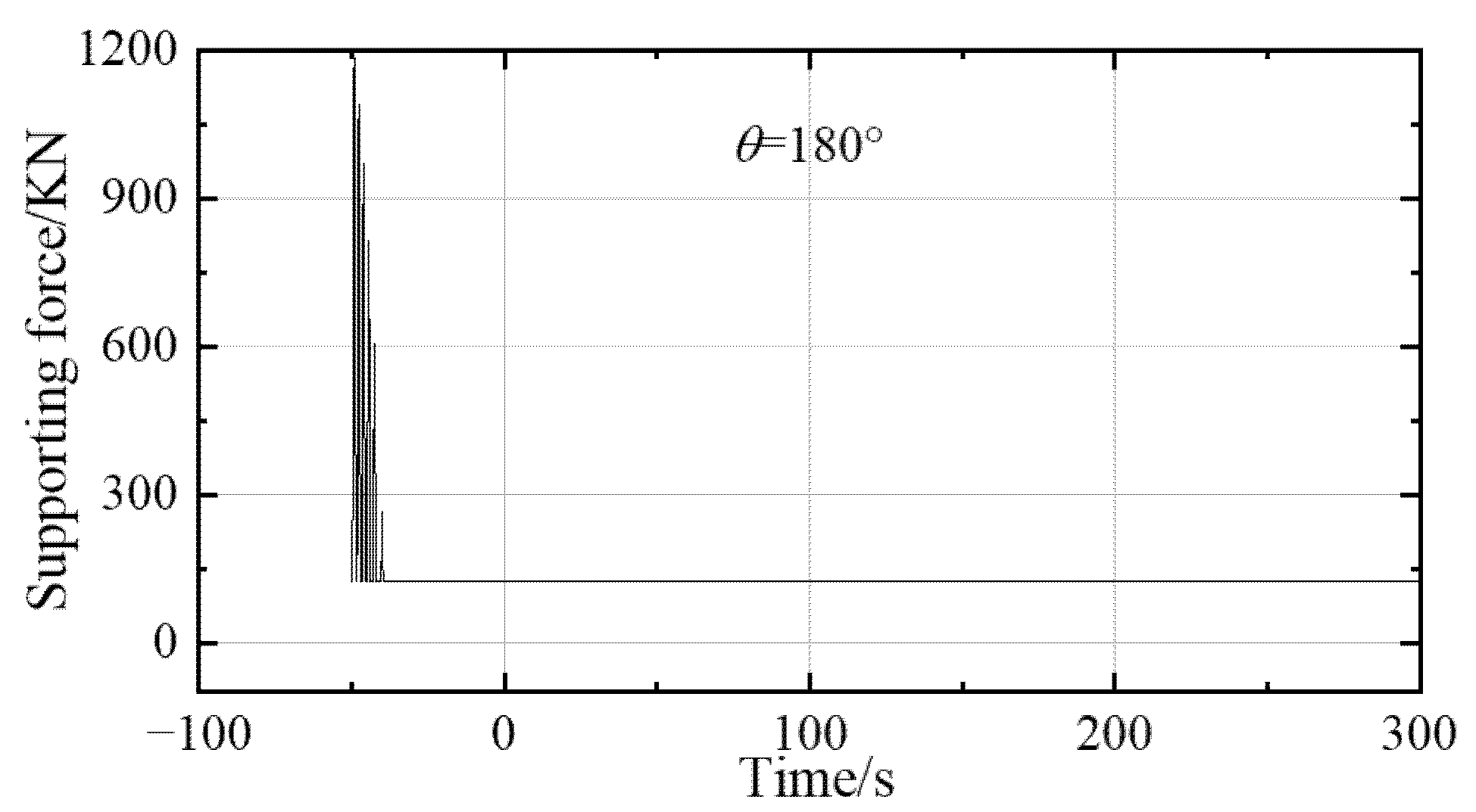
4.1. The Supporting Force of the Offloading Vessel under Different Wave Directions

As shown in Figure 10, the supporting force of the offloading vessel suddenly increases to a maximum value of mutation because of the instantaneous impact load at the moment of the hanging object being hoisted, under most wave directions. With time, the supporting force of the offloading vessel gradually decreases until the hanging object is placed on the support vessel (except for 45°, 60°, 120°, and 135°) and the supporting force of the deck of the offloading vessel stabilizes at 124.92 KN, which is roughly equal to the total gravity of the crane pivot and the crane arm. The maximum of the supporting force occurs under the wave direction of 90°, with the largest supporting force being 1200 KN. Under the wave directions of 45°, 60°, 120°, and 135°, respectively, it could be found that the hanging object could not be placed on the support vessel or it was simply suspended again by the offloading vessel, as the contact time is very short. Additionally, the hanging object would rotate around the top end of the crane wire and oscillate irregularly, with the impact load again occurring at a certain moment. Furthermore, the impact load again increases to a maximum value but it is much smaller than that when the hanging object is simply being hoisted, and the largest supporting force occurs under a wave direction of 90°. The reason for this phenomenon is that a wave direction of 90° makes the amplitude of roll and heave greater than that under the other wave directions; as the crane pivot is fixed with the deck of the vessel, to limit the motion of the crane pivot, the supporting force must increase at the same time.

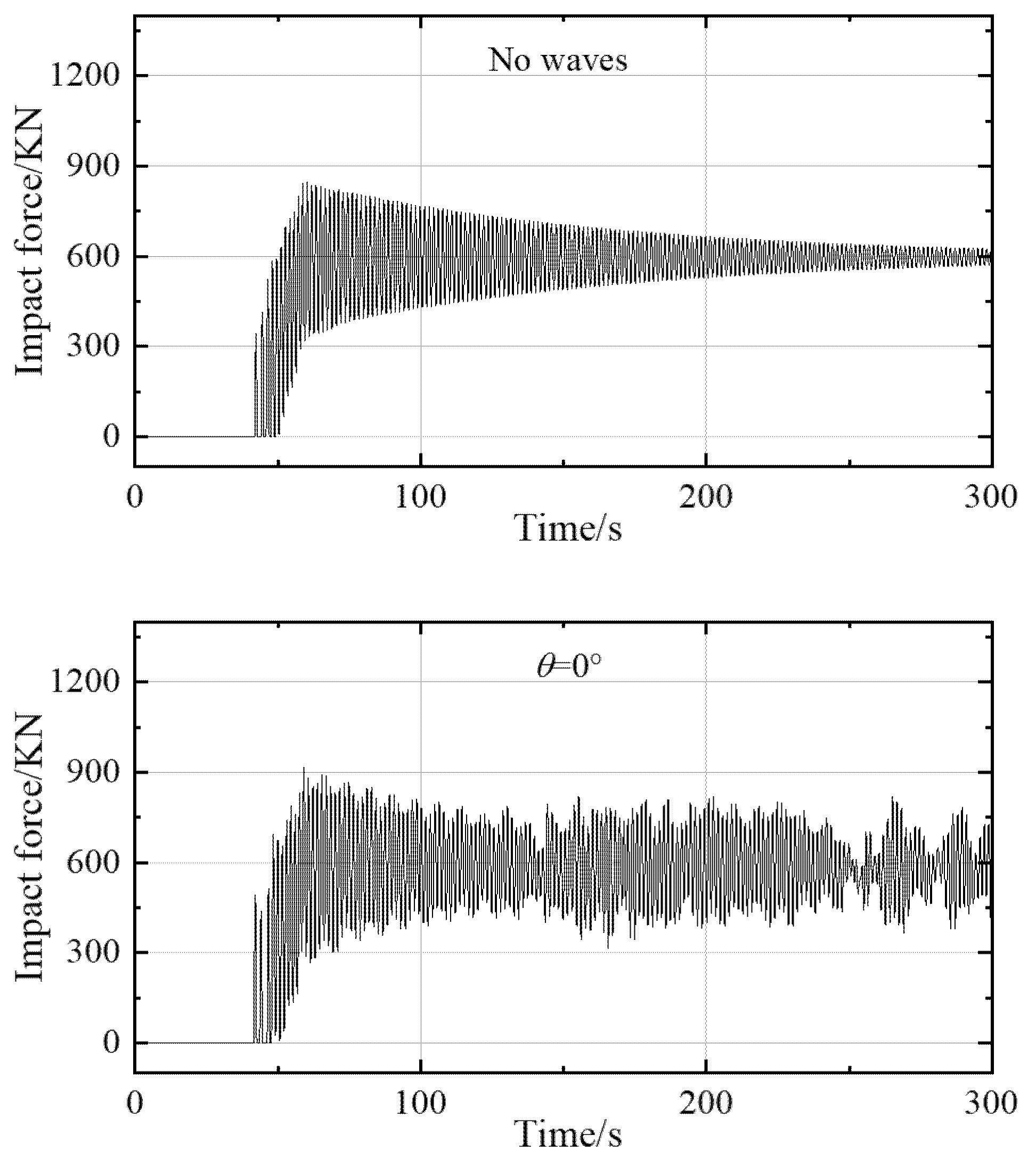
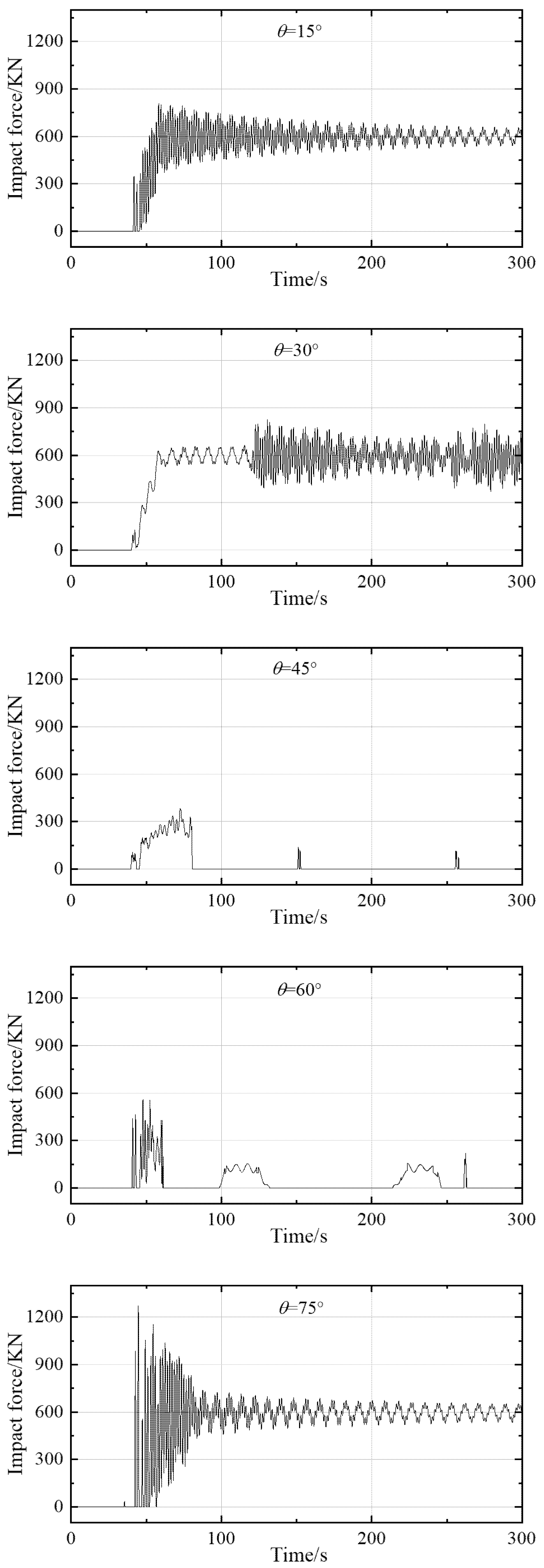
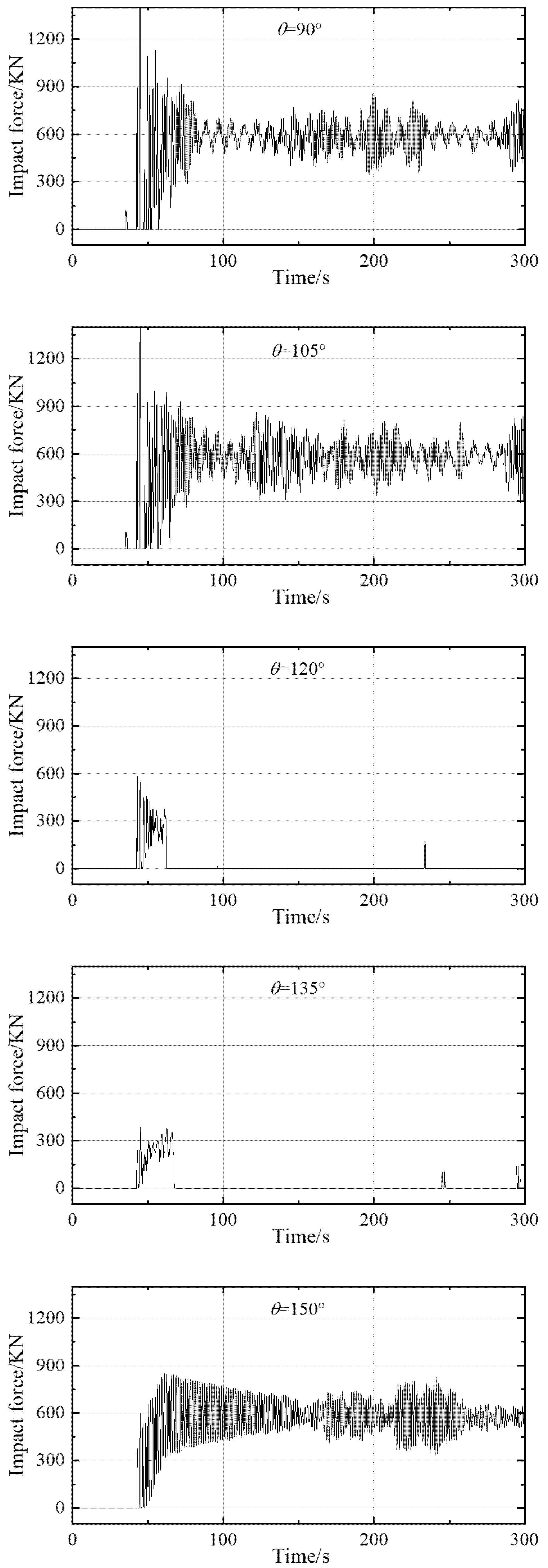
4.2. The Impact Force of the Offshore Crane Vessel under Different Wave Directions

As shown in Figure 11, there is no impact force between the support vessel and the hanging object during the beginning 37 s and no contact between the support vessel and the hanging object. Additionally, we have found that the collision between the support vessel and the hanging object happens at different times under different wave directions. However, the difference is not significant; the collision has basically happened in approximately 50 s. Because of the impact load at the moment the collision occurs, the impact force increases instantaneously, and then decreases. With time, the impact force increases and decreases irregularly and changes in a cyclical way. Under wave directions of 45°, 60°,120°, and 135°, respectively, by simulation, we have found that the hanging object could not be placed on the support vessel or it is simply suspended again by the offloading vessel, as the contact time is very short and as a result, the impact force finally decreases to 0 KN. The largest impact force occurs under a wave direction of 90°; the maximum force is 1600 KN. The reason for this phenomenon is that the wave direction of 90°makes the amplitude of roll and heave greater than under the other wave directions and then makes the collision between the support vessel and the hanging object occur frequently and violently, which makes the impact force greatly increased.

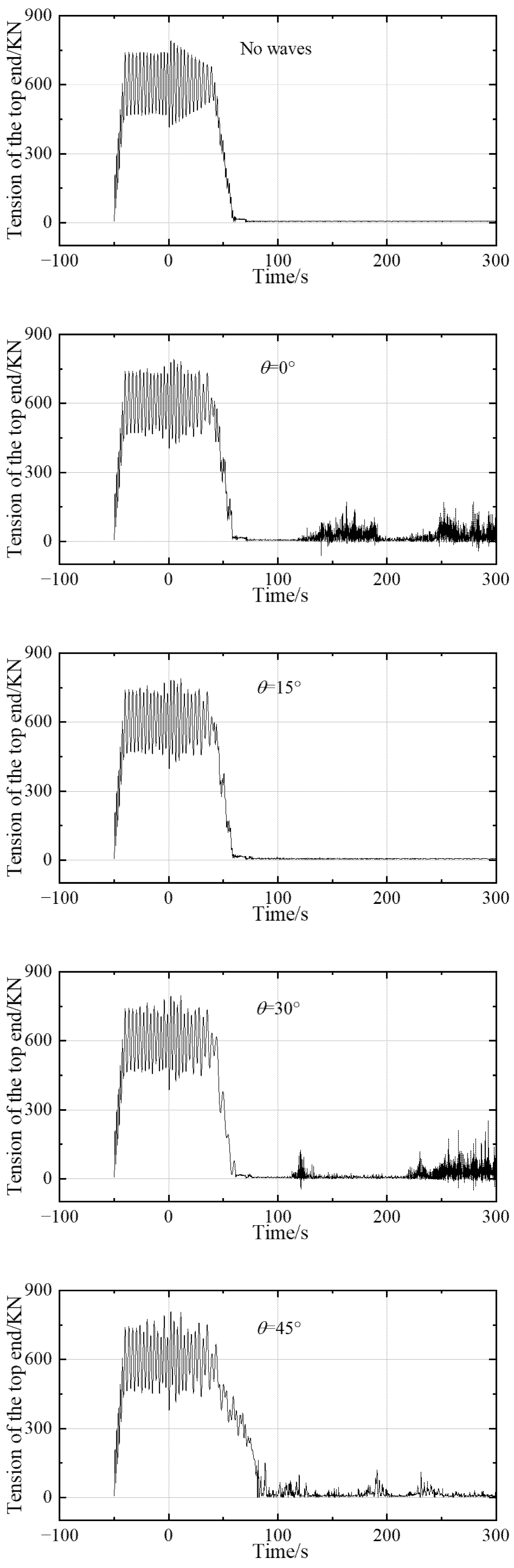
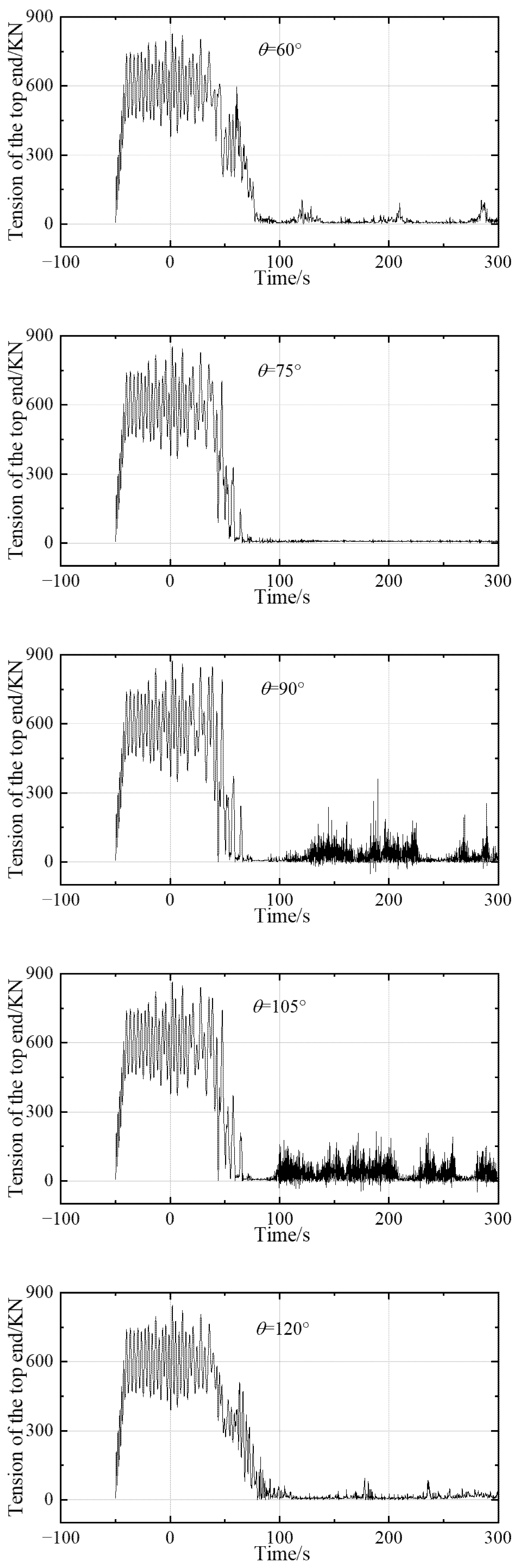
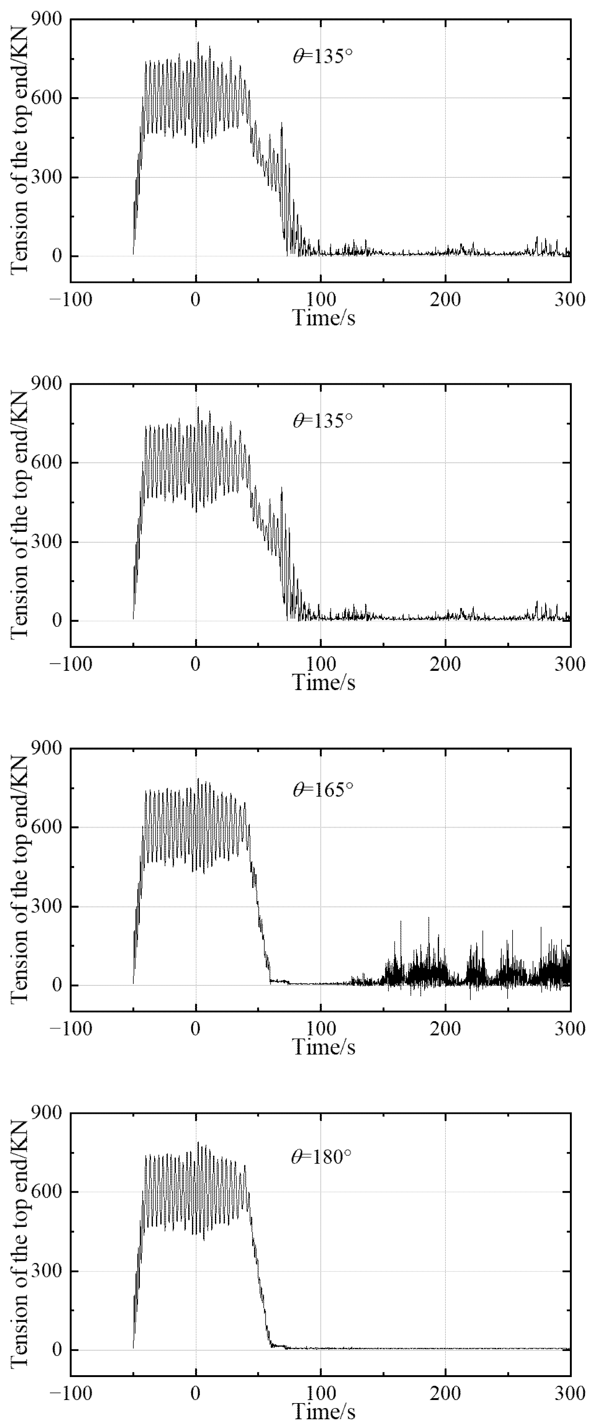
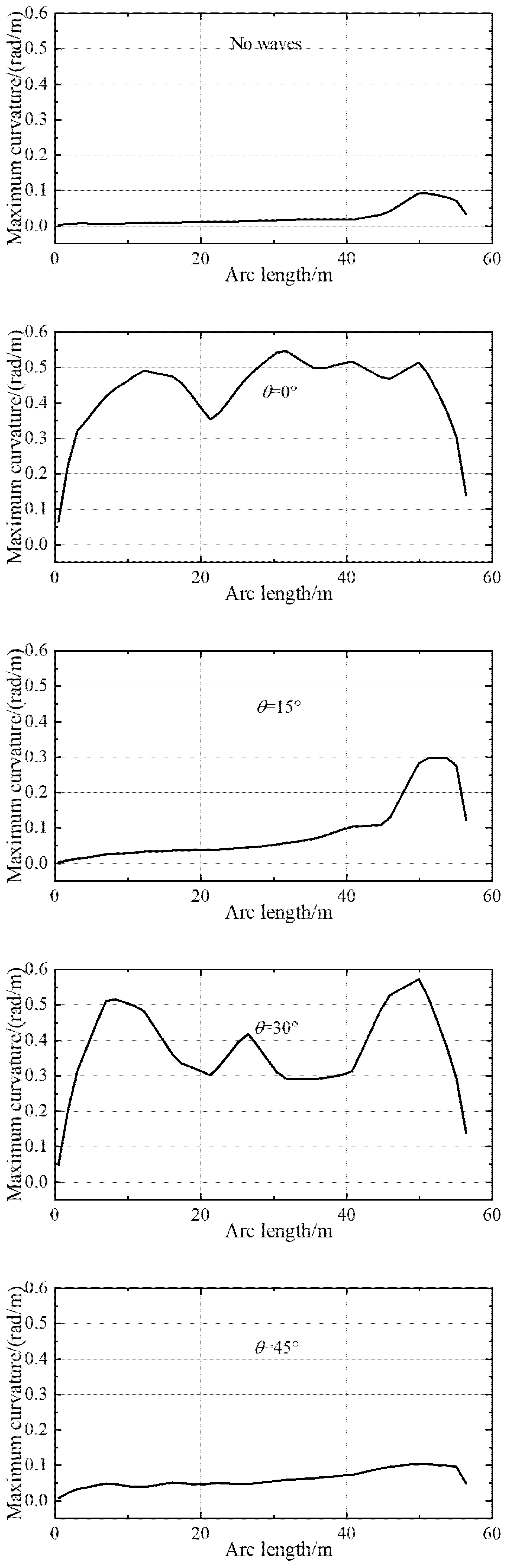
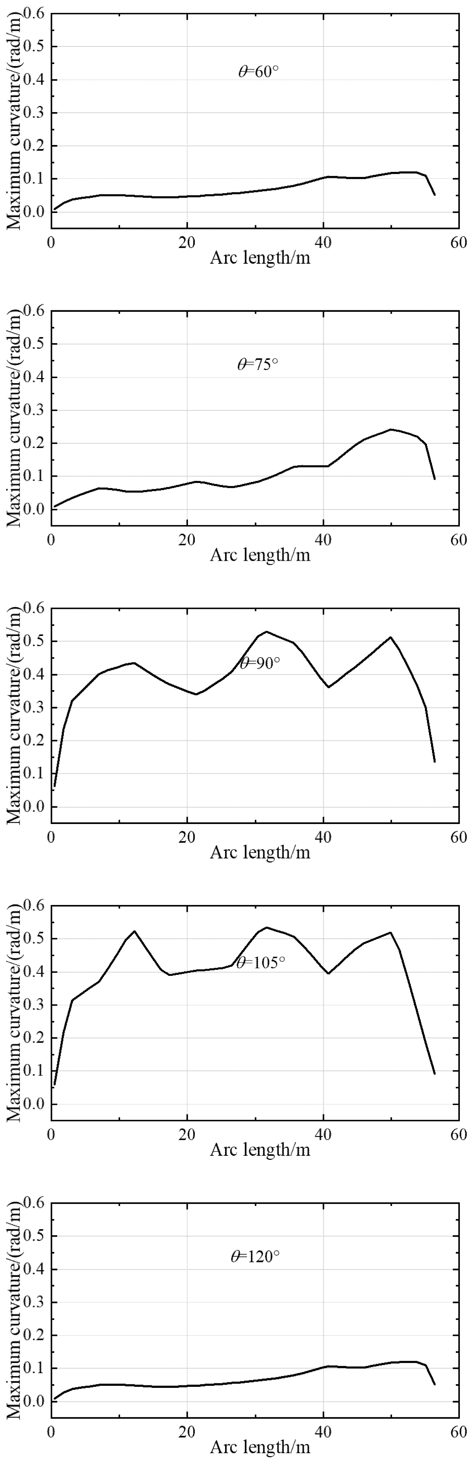
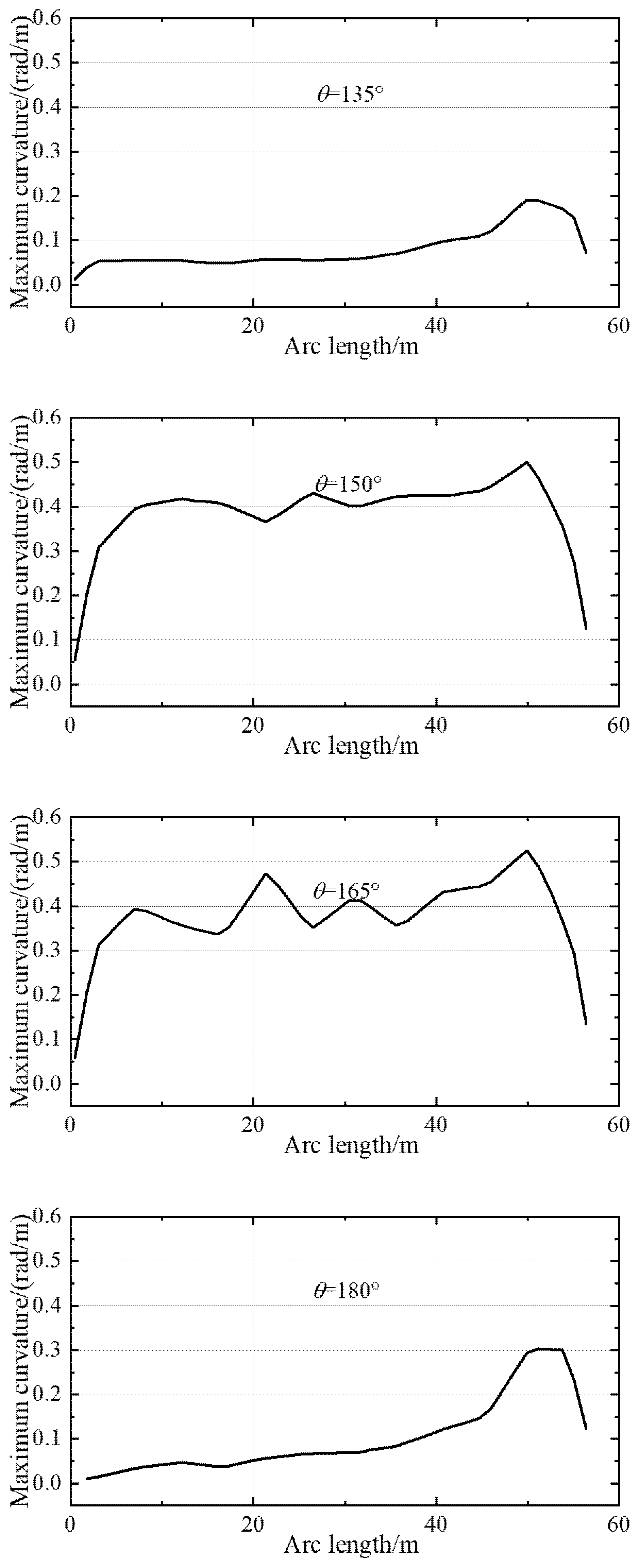
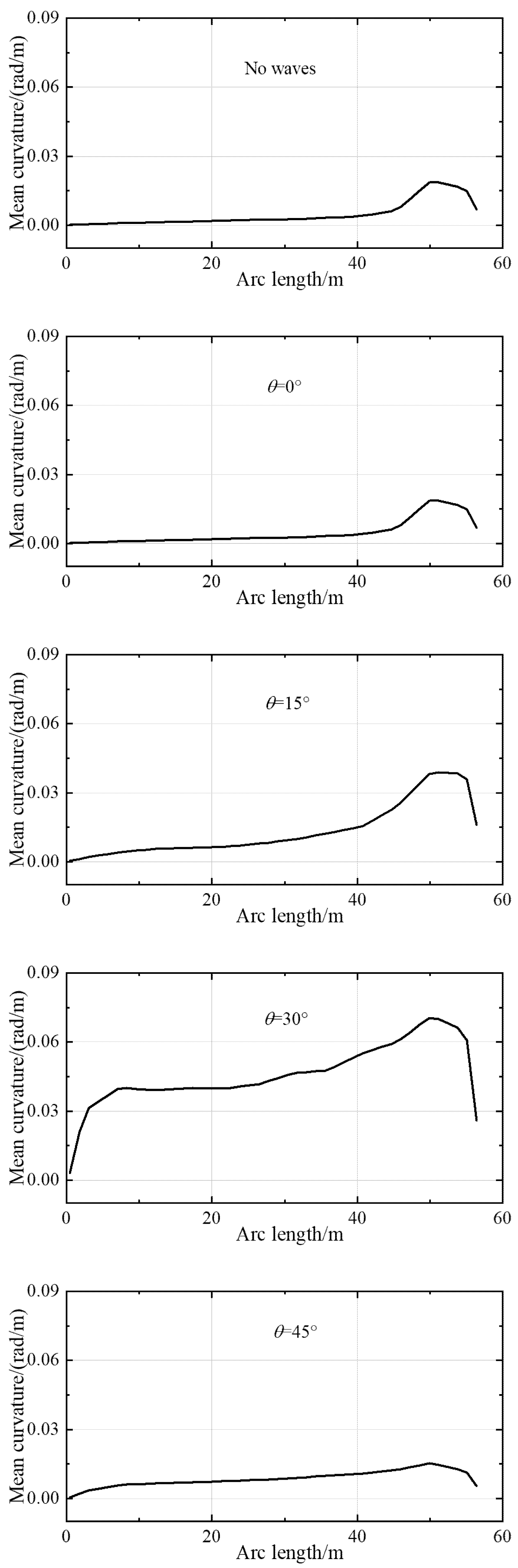
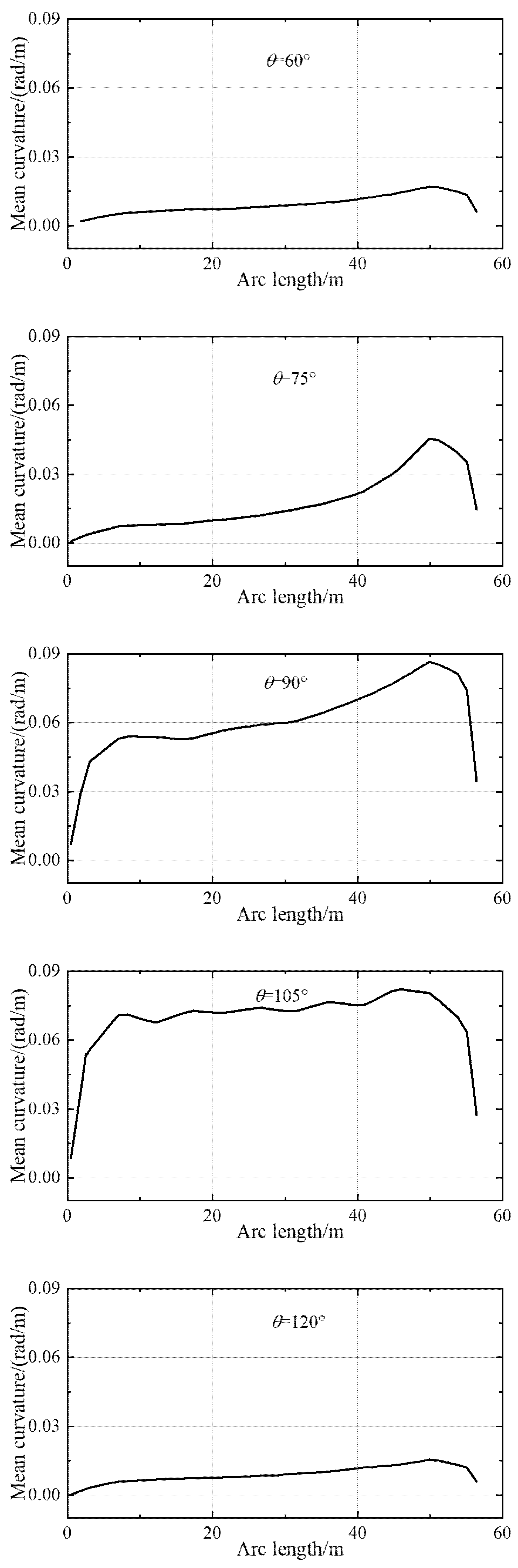
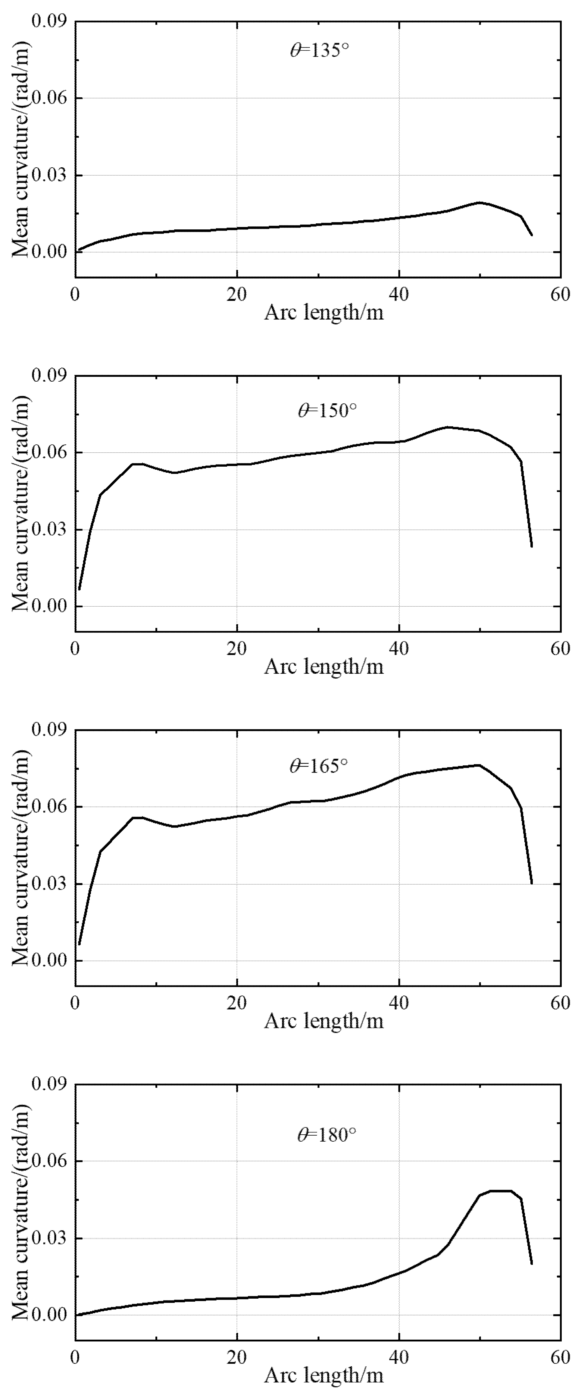
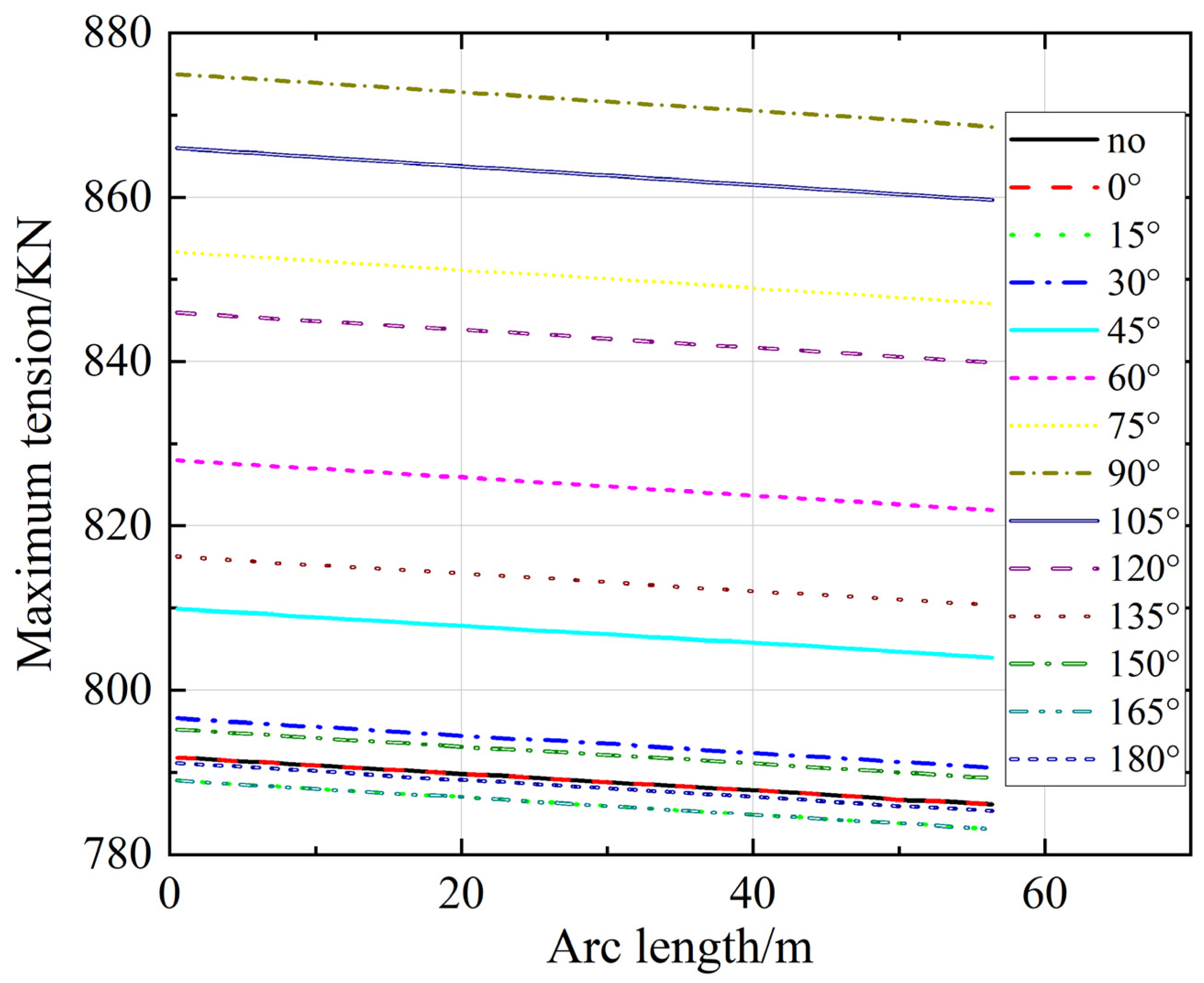
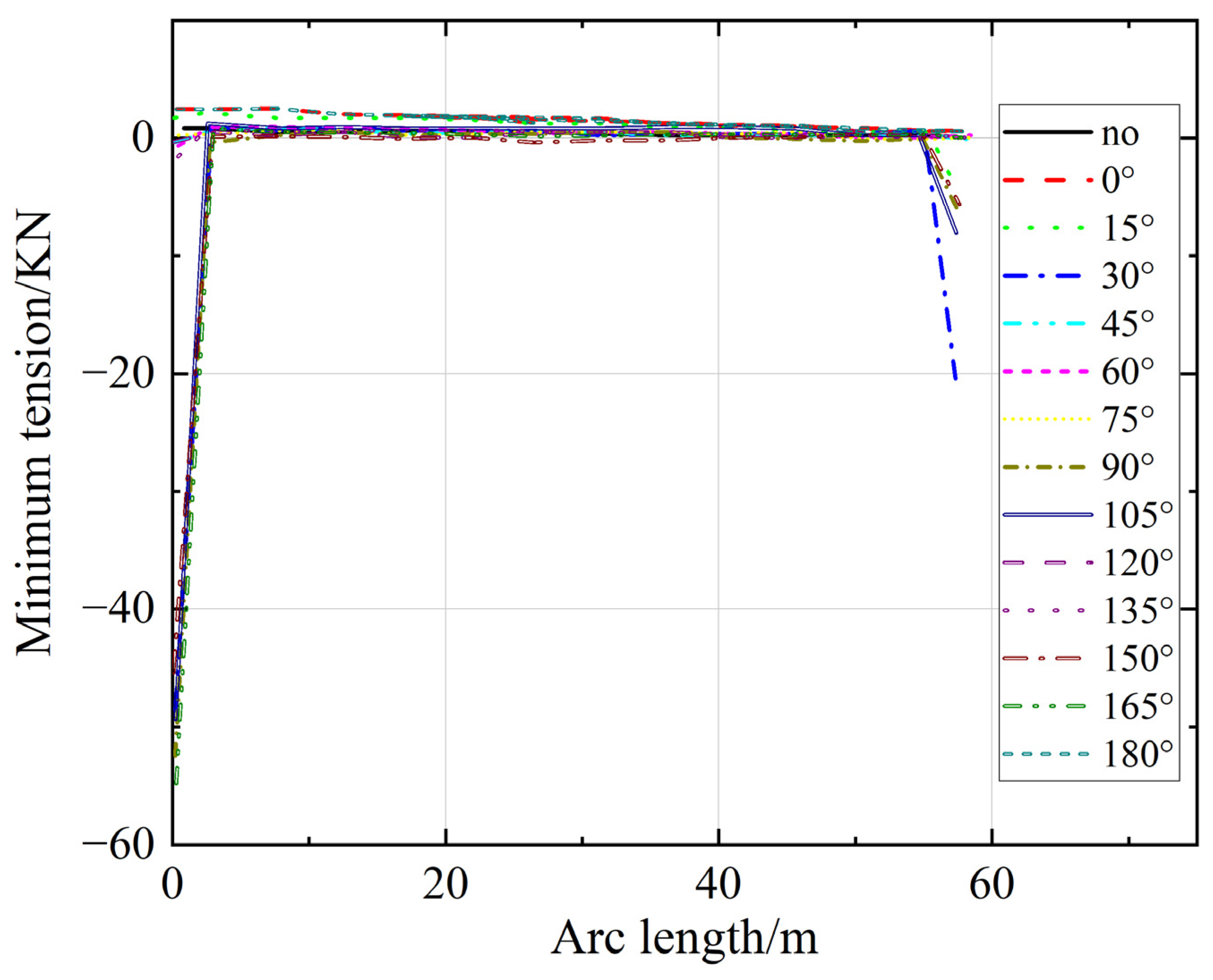
4.3. The Dynamic Response of the Crane Wire under Different Wave Directions

Figure 12, Figure 13, Figure 14, Figure 15 and Figure 16 show the dynamic response of the crane wire. As shown in Figure 12, before the hanging object is placed on the support vessel, because of the impact load at the moment of the collision occurring, the tension of the crane wire increases to a maximum value instantaneously (the value is different under different wave directions). Then it increases and decreases irregularly and changes in a cyclical way. At the time of the hanging object being placed on the deck of the support vessel, the tension of the crane wire will decrease sharply, but it still increases and decreases irregularly and changes in a cyclical way with a small amplitude along with the drift phenomenon of the support vessel. The maximum bending does not always occur at the same position under different wave directions. However, all maximum bending occurs along the length of the top end of the crane wire, from 50–55 m. Additionally, no matter the wave direction, the curvature is 0 at the top end and the bottom end of the crane wire. This means that any position of the crane wire must be straightened along the length direction at a certain time. Figure 15 shows that along the length direction, the maximum tension occurs at the top end of the crane wire. The minimum tension occurs at the bottom end of the crane wire, and the tension decreases linearly along the length direction, but the amplitude of the reduction is not severe, and the minimum tension at the top end does not occur under the wave direction of 0°; it is under the wave direction of 15° that the minimum tension occurs. Additionally, the maximum tension at the top end occurs under the wave direction of 90°. The reason for this phenomenon is that the wave direction of 90° makes the amplitude of roll and heave greater than under the other wave directions and then makes the crane arm undergo the same motion; as a result, that makes the dynamic response more frequent and violent than for the other wave directions. However, under the wave direction of 15°, in the coupling interaction, the dynamic response of the system caused by the direction plays a role in heave compensation; thus, the tension of the crane wire decreases to the minimum. Figure 16 illustrates that the parts of circulation that reciprocatively contract along the crane wire length mainly occur at the top position from 0–5 m and the end from 50–57 m, as the minimum tension of these parts has negative values, and it is in these positions where the contraction along the length direction occurs, but the other parts of the crane wire are in a state of being stretched along the length direction.

5. Conclusions

In this paper, the hydrodynamic characteristics of the full-circle swinging hoisting operation of a large revolving offshore crane vessel under different wave directions were studied. This study demonstrated the following:
(1) The supporting force of the deck of the offloading vessel suddenly increased to a maximum value of mutation because of the instantaneous impact load at the moment of the hanging object being hoisted under most wave directions. With time, the supporting force of the offloading vessel decreased gradually, until the hanging object was placed on the support vessel (except for 45°, 60°,120°, and 135°) and the supporting force of the deck of the offloading vessel stabilized at the total gravity of the crane pivot and the crane arm.
(2) Under wave directions of 45°, 60°, 120°, and 135°, it was found that the hanging object could not be placed on the support vessel or it was simply suspended again by the offloading vessel, as the contact time was very short. Therefore, it would be best to avoid working under those four wave directions or change the relative directions between the vessel and waves to ensure safety during operation.
(3) Both the largest supporting force of the offloading vessel and the largest impact force between the hanging object and the support vessel occurred under a wave direction of 90°. The minimum tension of the crane wire did not occur under a condition of no waves, but occurred under a wave direction of 15°. Therefore, it is better to work under a 15° wave direction to ensure safety during operation.
(4) The parts of circulation that reciprocatively contracted along the crane wire length mainly occurred at the top position from 0–5 m and the end from 50–57 m, which were prone to stress concentration and fatigue failure. This is a problem that should be paid attention to in the actual design process.

Author Contributions

Conceptualization, D.Z. and B.Z.; methodology, D.Z.; software, K.Z.; validation, D.Z. and K.Z.; formal analysis, D.Z. and B.Z.; investigation, K.Z. and B.Z; resources, D.Z.; data curation, K.Z.; writing—original draft preparation, D.Z.; writing—review and editing, D.Z.; visualization, K.Z.; supervision, D.Z.; funding acquisition, D.Z. and H.J. All authors have read and agreed to the published version of the manuscript.

Funding

This research was funded by Program for Scientific Research Start-up Funds of Guangdong Ocean University, grant number 060302072101, Zhanjiang Marine Youth Talent Project- Comparative Study and Optimization of Horizontal Lifting of Subsea Pipeline, grant number 2021E5011, and the National Natural Science Foundation of China, grant number 62272109.

Institutional Review Board Statement

Not applicable.

Informed Consent Statement

Not applicable.

Data Availability Statement

Not applicable.

Conflicts of Interest

The authors declare no conflict of interest.

References

  1. Koohi-Fayegh, S.; Rosen, M.A. A review of energy storage types, applications and recent developments. J. Energy Storage 2020, 27, 101047. [Google Scholar] [CrossRef]
  2. Sarkodie, S.A.; Adams, S. Renewable energy, nuclear energy, and environmental pollution: Accounting for political institutional quality in South Africa. Sci. Total Environ. 2018, 643, 1590–1601. [Google Scholar] [CrossRef] [PubMed]
  3. Barber, D.E.; Bonneson, G.W. Latest concepts in offshore lift crane design. In Proceedings of the Fall Meeting of the Society of Petroleum Engineers of AIME, Houston, TX, USA, 4–7 October 1970; OnePetro: Richardson, TX, USA, 1970. [Google Scholar]
  4. Hoffman, D.; Fitzerald, V.K. Systems approach to offshore crane ship operations. In Proceedings of the SNAME Annual Meeting, New York, NY, USA, 16–18 November 1978. [Google Scholar]
  5. Clauss, G.F.; Riekert, T. Operational limitations of offshore crane vessels. In Proceedings of the Offshore Technology Conference, Houston, TX, USA, 7–10 May 1990; OnePetro: Richardson, TX, USA, 1990. [Google Scholar]
  6. Chu, Y.; Æsøy, V.; Zhang, H.; Bunes, O. Modelling and simulation of an offshore hydraulic crane. In Proceedings of the 28th European Conference on Modelling and Simulation ECMS, Brescia, Italy, 27–30 May 2014; pp. 87–93. [Google Scholar]
  7. Shuguang, L.; Qian, G.; Wenpu, Z. Research on active heave compensation for offshore crane. In Proceedings of the 26th Chinese Control and Decision Conference (2014 CCDC), Changsha, China, 31 May–2 June 2014; IEEE: Piscataway, NJ, USA, 2014; pp. 1768–1772. [Google Scholar]
  8. Ismail, R.R.; That, N.D.; Ha, Q.P. Modelling and robust trajectory following for offshore container crane systems. Automat. Constr. 2015, 59, 179–187. [Google Scholar] [CrossRef]
  9. Kang, H.; Wu, Y.; Quen, L.K.; Tang, C.H.; Siow, C. Underwater target tracking of offshore crane system in subsea operations. In Proceedings of the 17th Asian Simulation Conference, Melaka, Malaysia, 27–29 August 2017; Springer: Singapore, 2017; pp. 126–137. [Google Scholar]
  10. Lee, D.; Kim, T.; Park, H.; Kim, Y. A study on the modeling and dynamic analysis of the offshore crane and payload. J. Korean Soc. Fish. Ocean. Technol. 2020, 56, 61–70. [Google Scholar] [CrossRef]
  11. Yang, T.; Sun, N.; Chen, H.; Fang, Y. Swing suppression and accurate positioning control for underactuated offshore crane systems suffering from disturbances. IEEE/CAA J. Autom. Sin. 2020, 7, 892–900. [Google Scholar] [CrossRef]
  12. Spathopoulos, M.P.; Fragopoulos, D. Pendulation control of an offshore crane. Int. J. Control 2004, 77, 654–670. [Google Scholar] [CrossRef]
  13. He, B.; Tang, W.; Cao, J. Virtual prototyping-based multibody systems dynamics analysis of offshore crane. Int. J. Adv. Manuf. Technol. 2014, 75, 161–180. [Google Scholar] [CrossRef]
  14. Fang, Y.; Wang, P.; Sun, N.; Zhang, Y. Dynamics analysis and nonlinear control of an offshore boom crane. IEEE Trans. Ind. Electron. 2014, 61, 414–427. [Google Scholar] [CrossRef]
  15. Chu, Y.; Æsøy, V.; Ehlers, S.; Zhang, H. Integrated multi-domain system modelling and simulation for offshore crane operations. Ship Technol. Res.=Schiffstech. 2015, 62, 36–46. [Google Scholar] [CrossRef] [Green Version]
  16. Shen, X.; Liu, S.; Zhang, C.; Bao, J. Intelligent material distribution and optimization in the assembly process of large offshore crane lifting equipment. Comput. Ind. Eng. 2021, 159, 107496. [Google Scholar] [CrossRef]
  17. Ye, J.; Roy, S.; Godjevac, M.; Reppa, V.; Baldi, S. Robustifying dynamic positioning of crane vessels for heavy lifting operation. IEEE/CAA J. Autom. Sin. 2021, 8, 753–765. [Google Scholar] [CrossRef]
  18. Fotland, G.; Haskins, C.; Rølvåg, T. Trade study to select best alternative for cable and pulley simulation for cranes on offshore vessels. Syst. Eng. 2020, 23, 177–188. [Google Scholar] [CrossRef] [Green Version]
  19. Saghafi Zanjani, M.; Mobayen, S. Anti-sway control of offshore crane on surface vessel using global sliding mode control. Int. J. Control 2022, 95, 2267–2278. [Google Scholar] [CrossRef]
  20. Osiński, M.; Maczyński, A.; Wojciech, S. The influence of ship’s motion in regular wave on dynamics of an offshore crane. Arch. Mech. Eng. 2004, 51, 131–163. [Google Scholar]
  21. Sanfilippo, F.; Hatledal, L.I.; Zhang, H.; Rekdalsbakken, W.; Pettersen, K.Y. A wave simulator and active heave compensation framework for demanding offshore crane operations. In Proceedings of the 2015 IEEE 28th Canadian Conference on Electrical and Computer Engineering (CCECE), Halifax, NS, Canada, 3–6 May 2015; IEEE: Piscataway, NJ, USA, 2015; pp. 1588–1593. [Google Scholar]
  22. Nam, B.W.; Kim, N.W.; Hong, S.Y. Experimental and numerical study on coupled motion responses of a floating crane vessel and a lifted subsea manifold in deep water. Int. J. Nav. Arch. Ocean 2017, 9, 552–567. [Google Scholar] [CrossRef]
  23. Cibicik, A.; Egeland, O. Determination of constraint forces for an offshore crane on a moving base. In Proceedings of the 2018 5th International Conference on Control, Decision and Information Technologies (CoDIT), Thessaloniki, Greece, 10–13 April 2018; IEEE: Piscataway, NJ, USA, 2018; pp. 233–240. [Google Scholar]
  24. Chen, H.; Sun, N. An output feedback approach for regulation of 5-DOF offshore cranes with ship yaw and roll perturbations. IEEE Trans. Ind. Electron. 2021, 69, 1705–1716. [Google Scholar] [CrossRef]
  25. Than, T.K.; Langen, I.; Birkeland, O. Modelling and simulation of offshore crane operations on a floating production vessel. In Proceedings of the Twelfth International Offshore and Polar Engineering Conference, Kitakyushu, Japan, 26–31 May 2002; OnePetro: Richardson, TX, USA, 2002. [Google Scholar]
  26. Hannan, M.A.; Bai, W. Analysis of nonlinear dynamics of fully submerged payload hanging from offshore crane vessel. Ocean Eng. 2016, 128, 132–146. [Google Scholar] [CrossRef]
  27. Ye, J.; Godjevac, M.; Baldi, S.; Hopman, H. Joint estimation of vessel position and mooring stiffness during offshore crane operations. Automat. Constr. 2019, 101, 218–226. [Google Scholar] [CrossRef]
  28. Zhao, Y.; Cheng, Z.; Gao, Z.; Sandvik, P.C.; Moan, T. Numerical study on the feasibility of offshore single blade installation by floating crane vessels. Mar. Struct. 2019, 64, 442–462. [Google Scholar] [CrossRef]
  29. Farhan, R.A.; Djatmiko, E.B.; Murdjito, M.; Ghofur, A. Experimental study and numerical analysis of crane operability in floating crane catamaran. Int. J. Offshore Coast. Eng. (IJOCE) 2021, 5, 50–57. [Google Scholar] [CrossRef]
  30. Landsverk, R.; Zhou, J.; Hovland, G.; Zhang, H. Modeling of Offshore Crane and Marine Craft in Wave Motion. In Proceedings of the 2020 15th IEEE Conference on Industrial Electronics and Applications (ICIEA), Kristiansand, Norway, 9–13 November 2020; IEEE: Piscataway, NJ, USA, 2020; pp. 1463–1470. [Google Scholar]
  31. Chakrabarti, S. Empirical calculation of roll damping for ships and barges. Ocean Eng. 2001, 28, 915–932. [Google Scholar] [CrossRef]
  32. Orcina. OrcaFlex Manual. 2015. Available online: http://www.orcina.com/SoftwareProducts/OrcaFlex/Validation/index/.pdf (accessed on 1 January 2015).
  33. Aoheds. Flexcom Manual. 2018. Available online: https://www.flexcomonline.com/applications/ (accessed on 1 January 2018).
  34. Denzler, J.; Hinz, A.M. Catenaria vera-the true catenary. Expo. Math. 1999, 17, 117–142. [Google Scholar]
Figure 1. The lumped mass model.
Jmse 11 00197 g001
Figure 2. The coordinate systems.
Jmse 11 00197 g002
Figure 3. The wave directions.
Jmse 11 00197 g003
Figure 4. The function of the winch.
Jmse 11 00197 g004
Figure 5. The function of the link.
Jmse 11 00197 g005
Figure 6. The schematic model of full-circle swing hoisting operation.
Jmse 11 00197 g006
Figure 7. The bending moment and the time history of the effective tension.
Jmse 11 00197 g007
Figure 8. The bending moment distribution of different segment lengths along the length direction.
Jmse 11 00197 g008aJmse 11 00197 g008b
Figure 9. The catenary shape.
Jmse 11 00197 g009
Figure 10. The supporting force of the offloading vessel under different wave directions.
Jmse 11 00197 g010aJmse 11 00197 g010bJmse 11 00197 g010cJmse 11 00197 g010d
Figure 11. The impact force of the offshore crane vessel under different wave directions.
Jmse 11 00197 g011aJmse 11 00197 g011bJmse 11 00197 g011cJmse 11 00197 g011d
Figure 12. The tension of the top end of the crane wire under different wave directions.
Jmse 11 00197 g012aJmse 11 00197 g012bJmse 11 00197 g012c
Figure 13. The maximum curvature of the crane wire along the length direction.
Jmse 11 00197 g013aJmse 11 00197 g013bJmse 11 00197 g013c
Figure 14. The mean curvature of the crane wire along the length direction.
Jmse 11 00197 g014aJmse 11 00197 g014bJmse 11 00197 g014c
Figure 15. The maximum tension of the crane wire along the length direction.
Jmse 11 00197 g015
Figure 16. The minimum tension of the crane wire along the length direction.
Jmse 11 00197 g016
Table 1. The comparison between calculation results and theoretical results.
Segmented NodeCalculation Results (KN)Difference (%)
1019.913540.2100
2019.867440.0220
3019.869770.0103
4019.870660.0058
6019.871300.0026
12019.871680.0006
Disclaimer/Publisher’s Note: The statements, opinions and data contained in all publications are solely those of the individual author(s) and contributor(s) and not of MDPI and/or the editor(s). MDPI and/or the editor(s) disclaim responsibility for any injury to people or property resulting from any ideas, methods, instructions or products referred to in the content.

