
Effectiveness of the Speed Reduction Strategy on Exhaust Emissions and Fuel Oil Consumption of a Marine Generator Engine for DC Grid Ships

 ,
,  ,
, 
 and
and
Abstract
:1. Introduction
2. Experimental Analysis
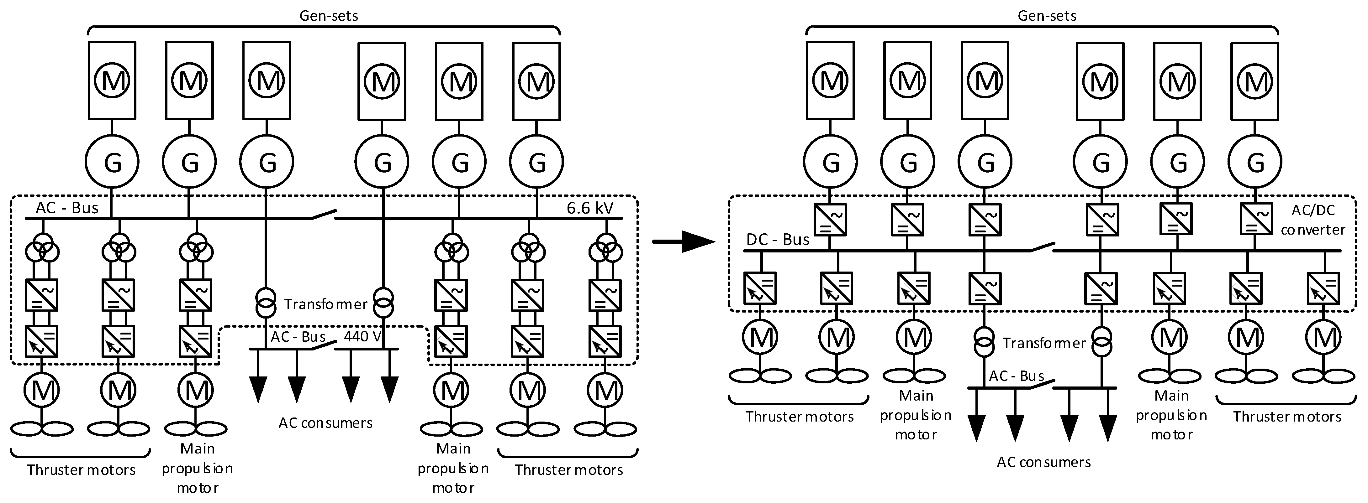
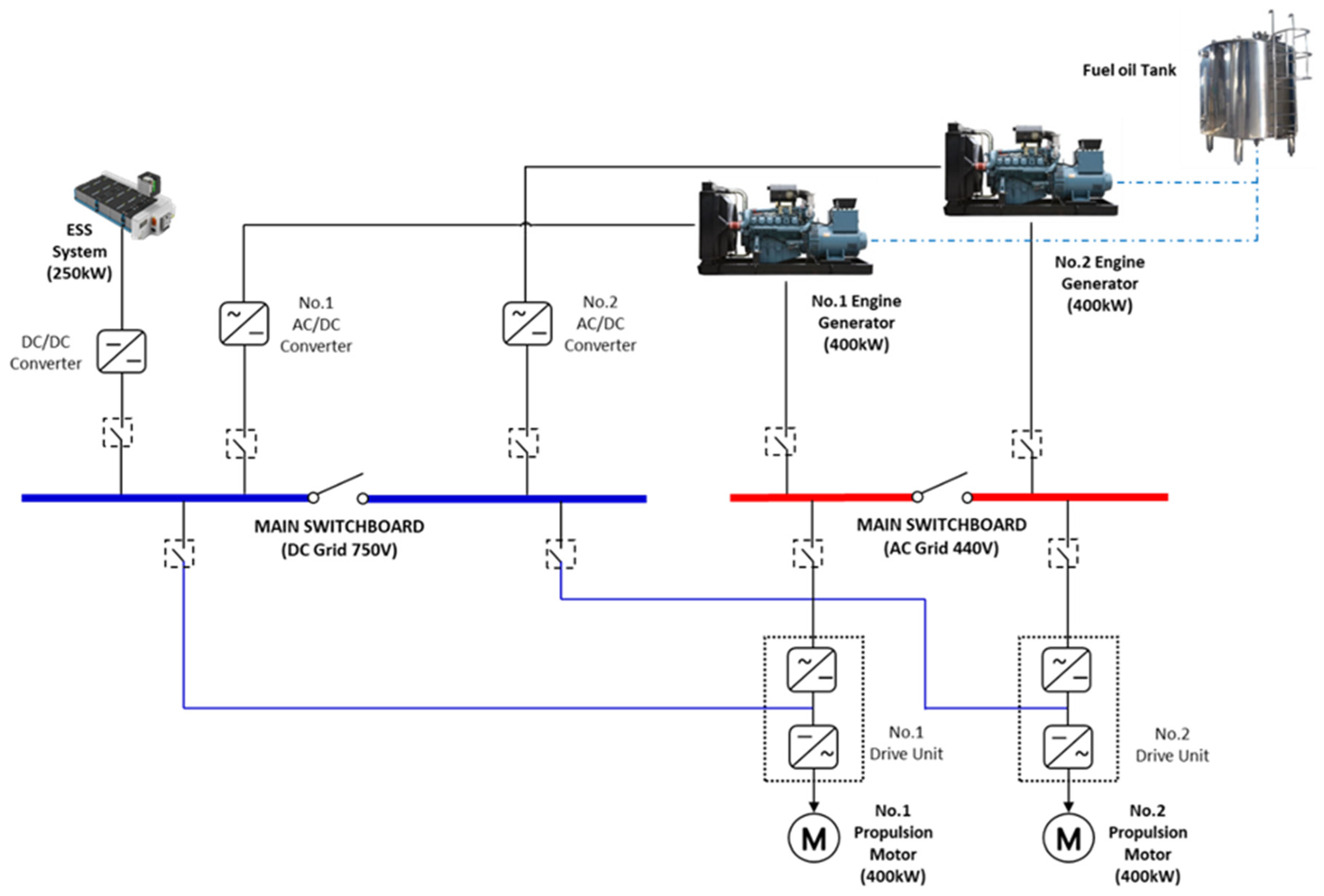
2.1. Designing of DC Grid System for the MASTC Laboratory
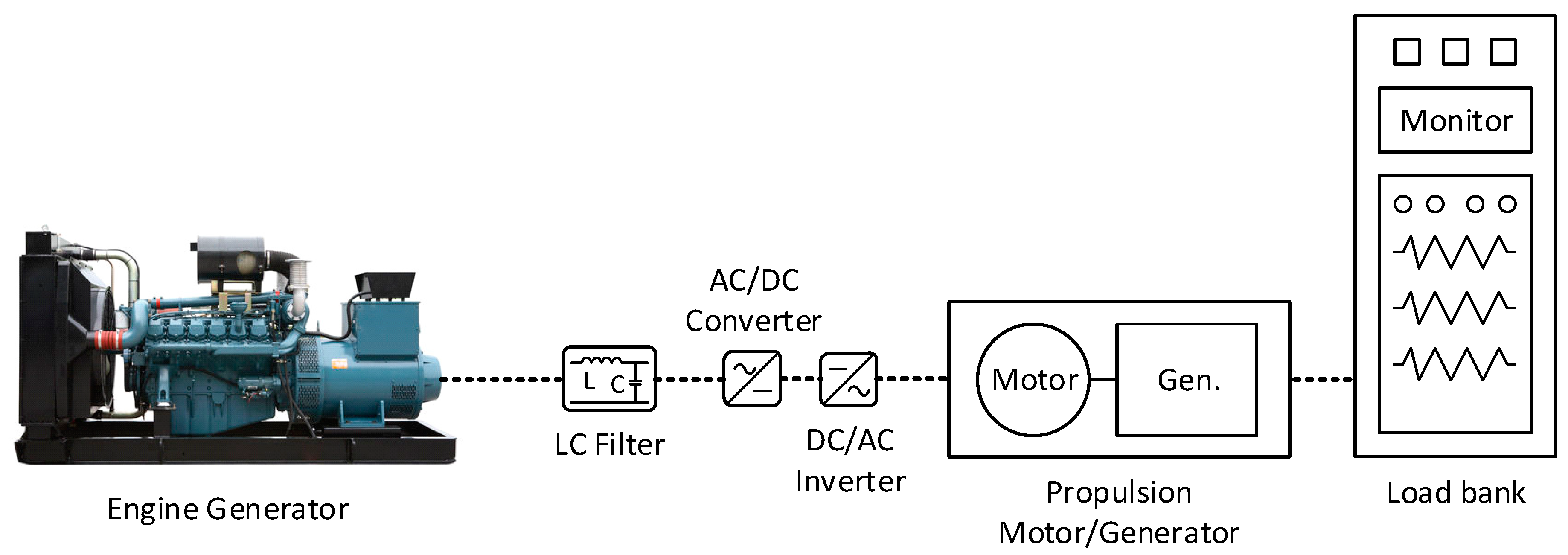
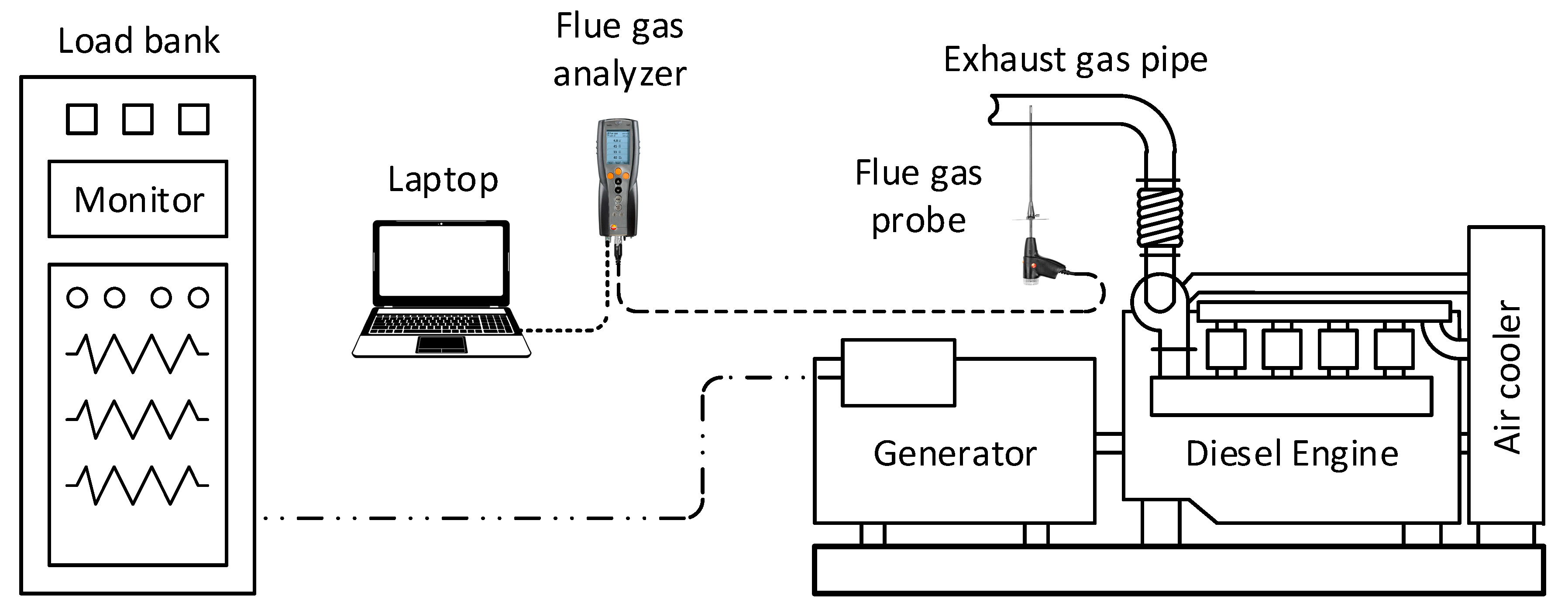
2.2. Experimental Setup and Equipment
2.3. Experiment Conditions
3. Experiment Results
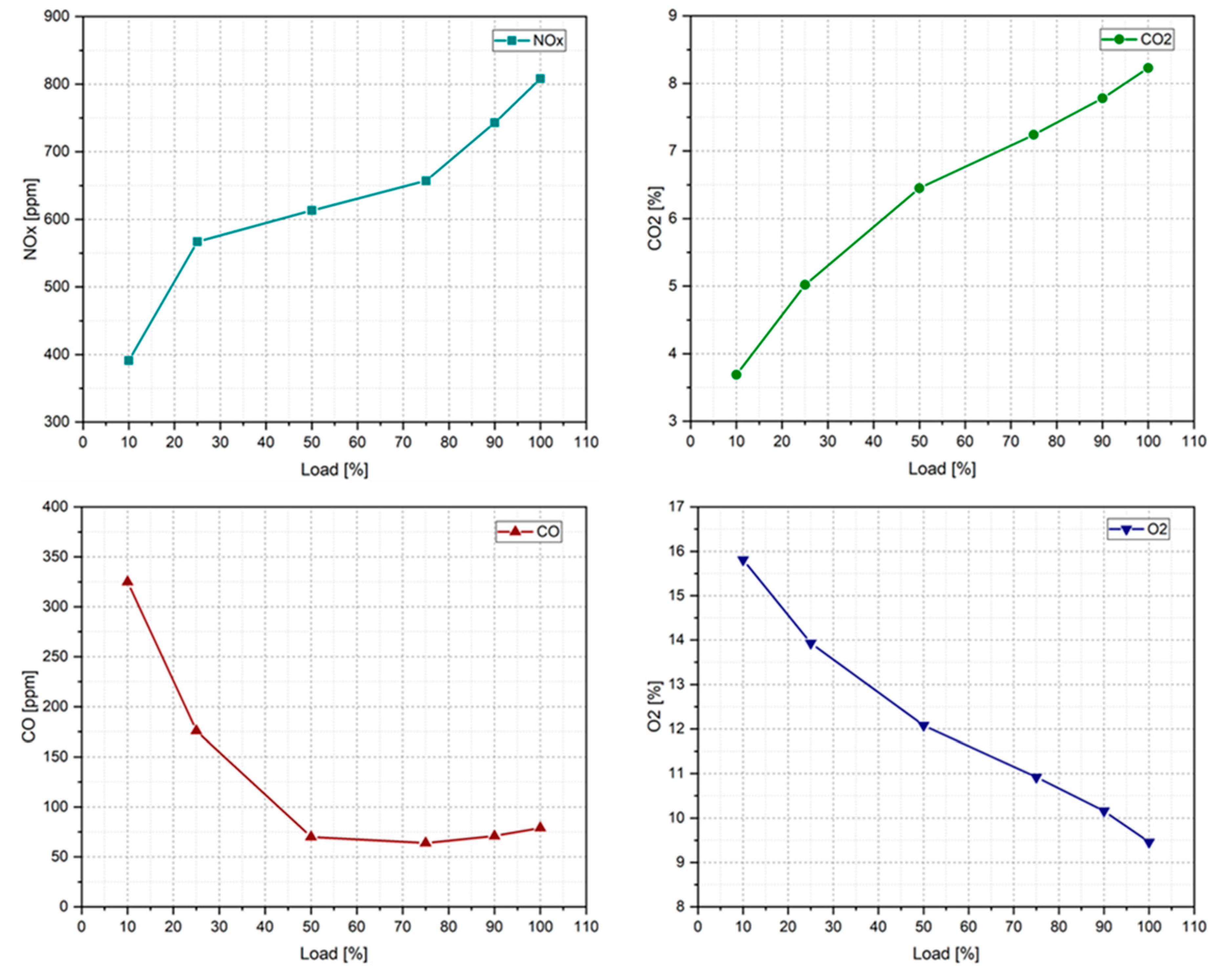
3.1. Effects of the Engine Load on Fuel Consumption and Emissions at the Rated Engine Speed
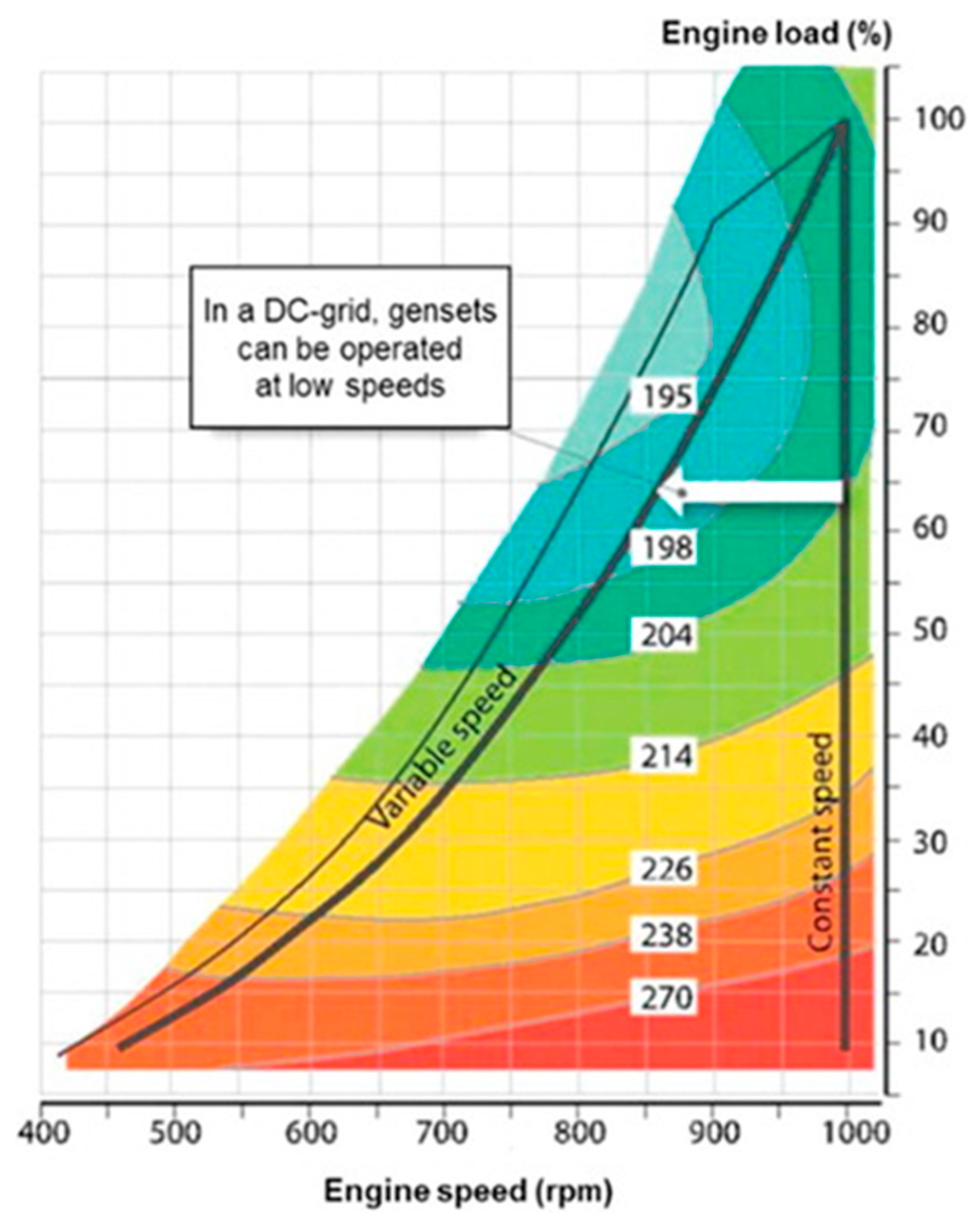
3.2. Effectiveness of the Engine Speed Reduction Strategy
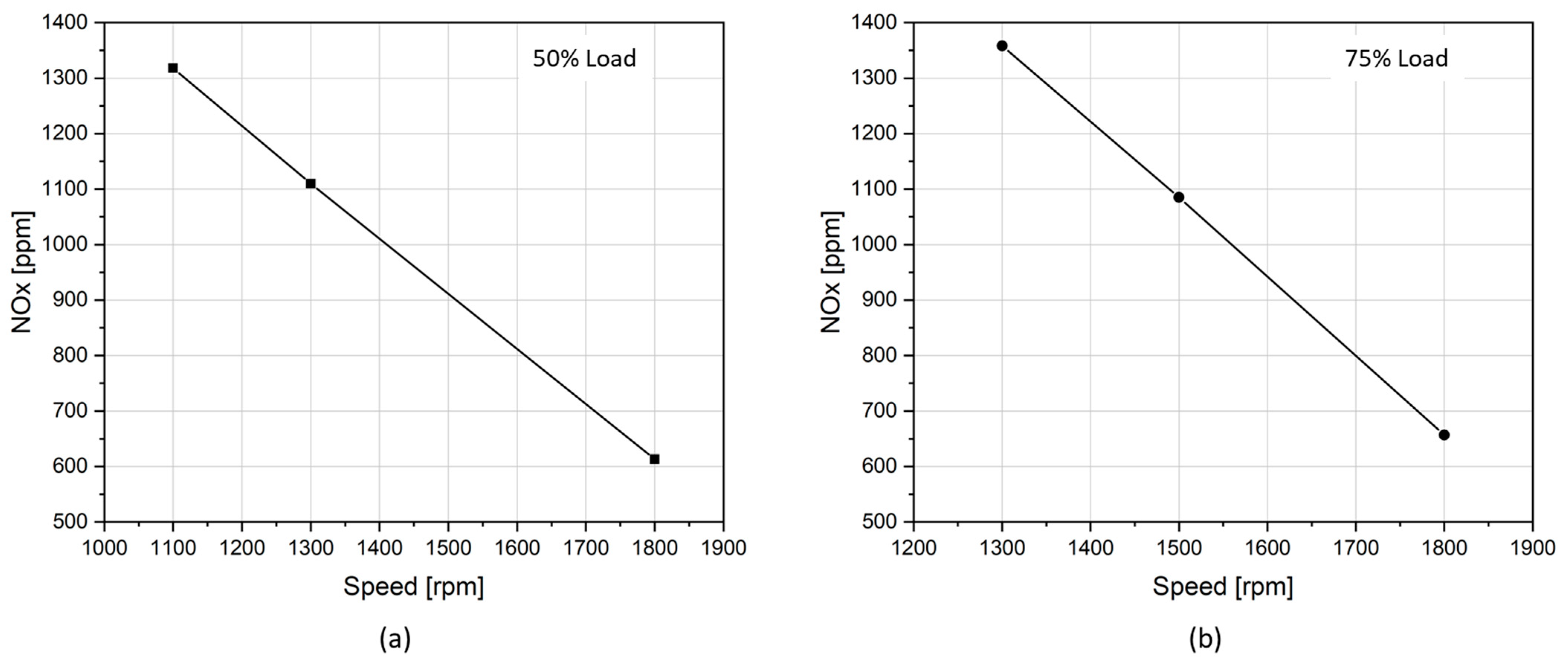
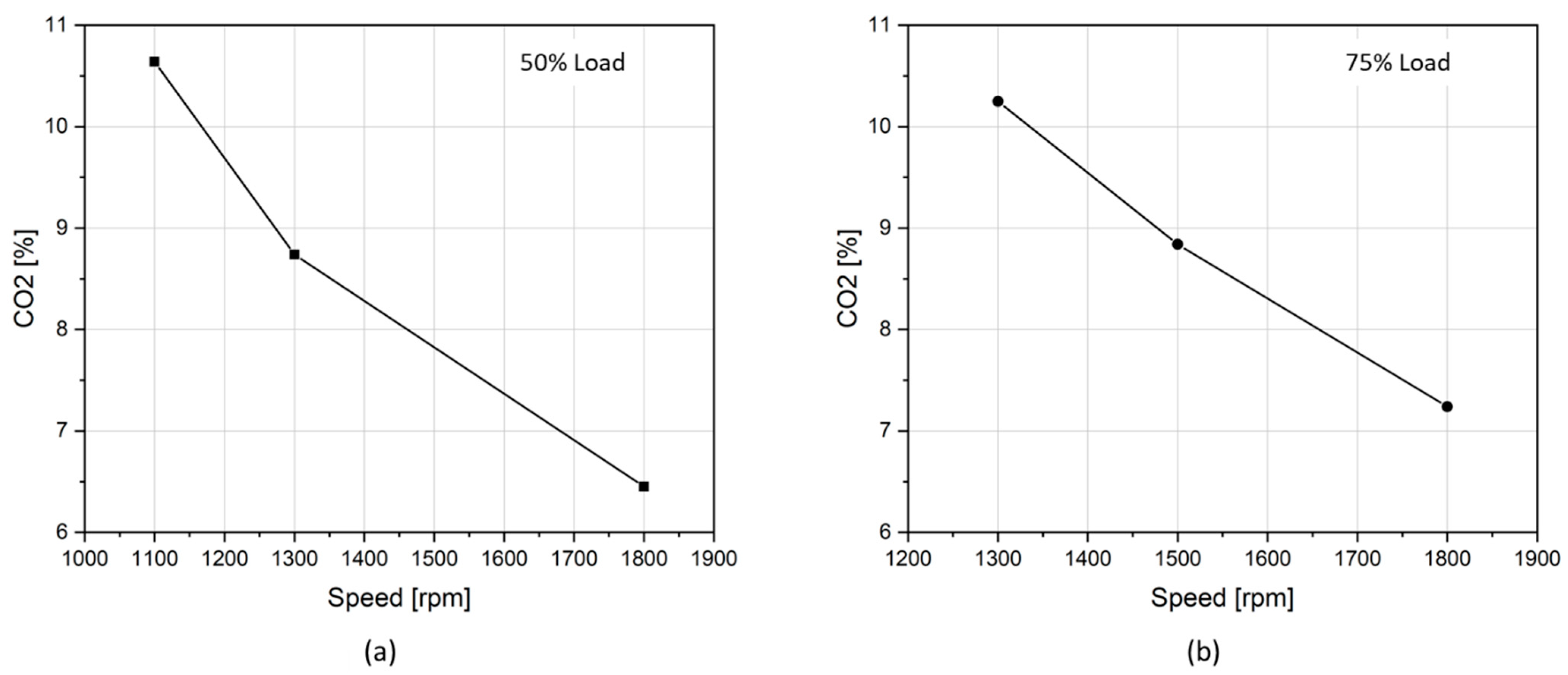
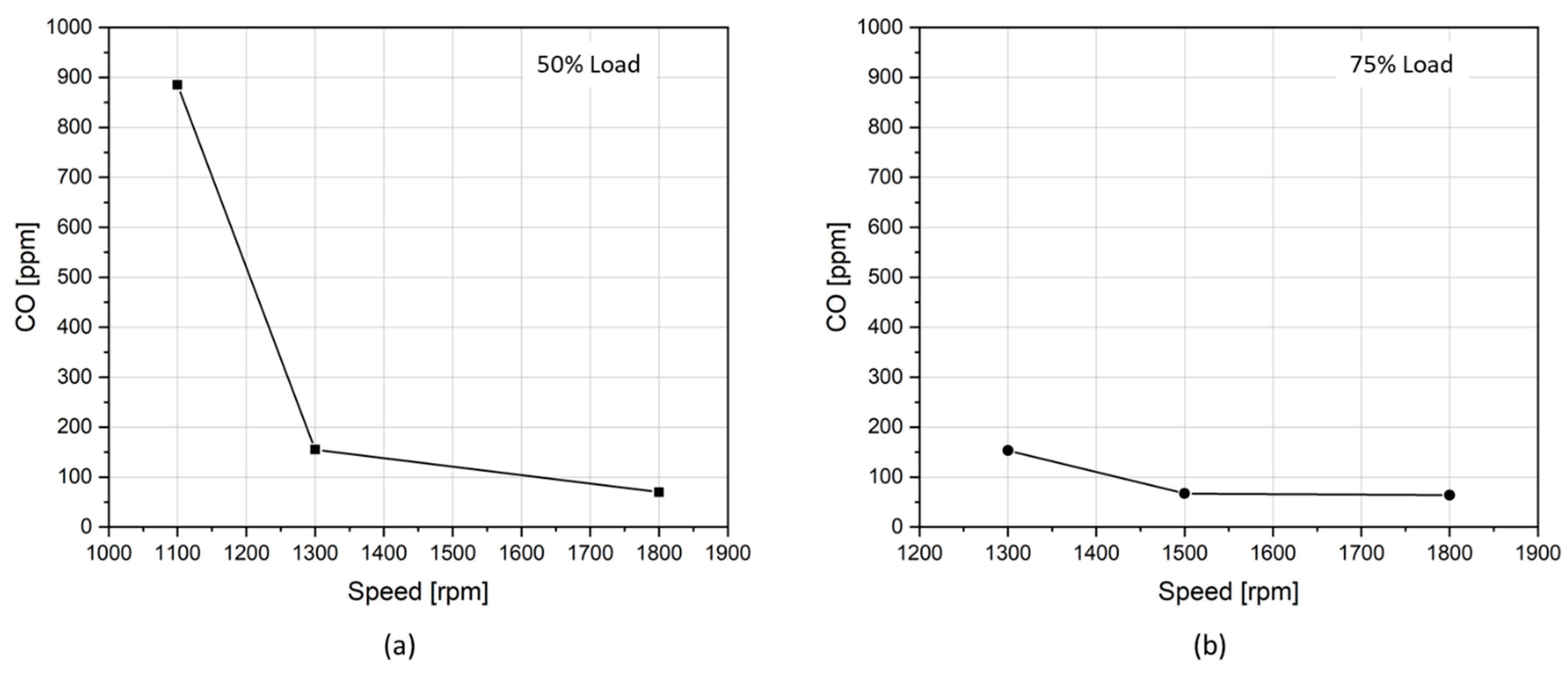
3.2.1. Effectiveness of the Engine Speed Reduction Strategy on Exhaust Gas Emissions
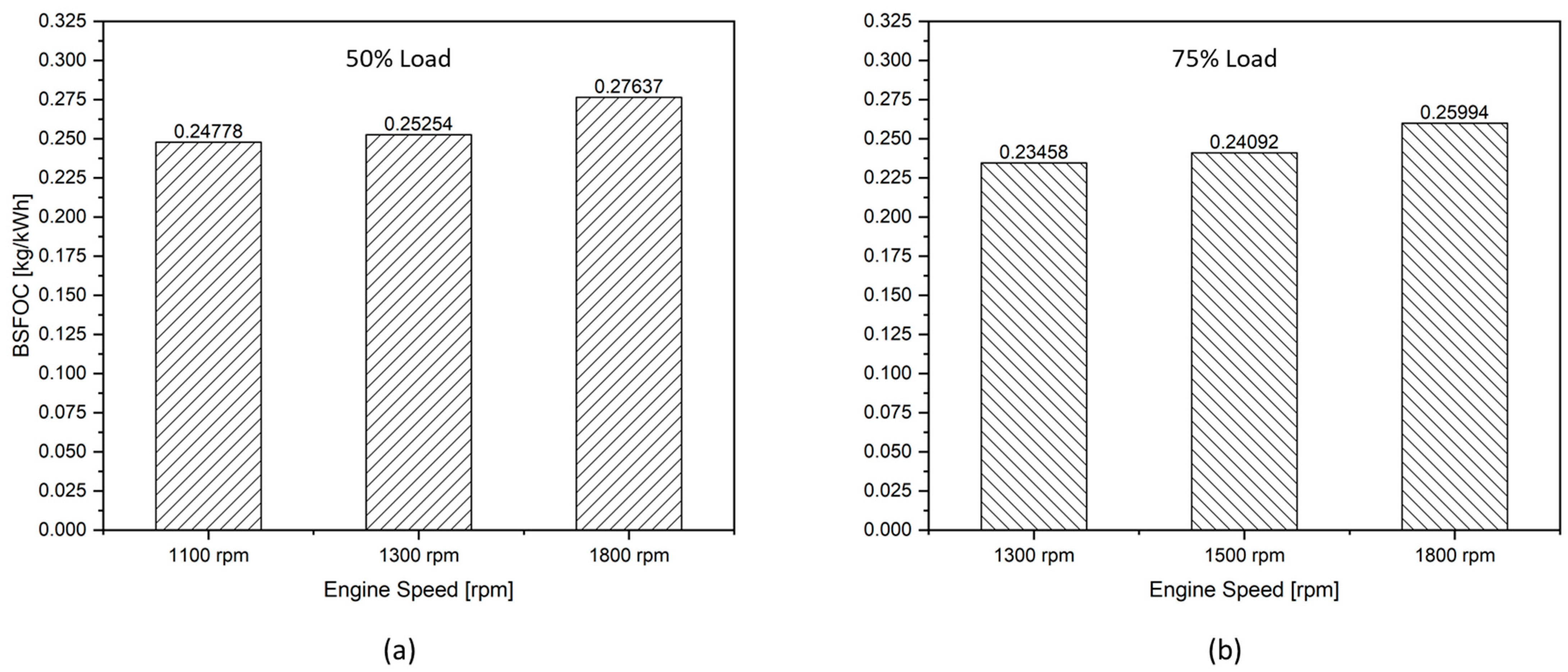
3.2.2. Effectiveness of the Engine Speed Reduction Strategy on Fuel Oil Consumption
4. Conclusions and Suggestions
- The fuel consumption was reduced but emission mass fraction in the exhaust gas was increased when the engine load was kept unchanged while the engine speed was reduced.
- The study showed economic benefits in reducing fuel consumption but incurred penalties for the emission performance of 4-stroke generator engines equipped with a cam-driven plunger diesel injection system when applying the engine speed reduction strategy. In the other words, the engine speed reduction strategy is not suitable for 4-stroke generator engines which use a cam-driven plunger diesel injection system for emission reduction purposes. This is because the combustion quality of engines using a cam-driven fuel injection system is greatly decreased when the engine is running at low speeds, resulting in increases in emissions mass fraction in the exhaust gas.
- The problems in emission performance of engines might be solved if applying the engine speed reduction strategy on engines equipped with an electronically-controlled fuel injection system, a common rail fuel system, for instance. The highly flexible features of the common rail fuel system help to control fuel injection timing, quantity, and injection pressure independently of engine speed and load. It also offers multiple-injection strategy options for further emission reduction purposes [29]. In such engines, the fuel injection properties can be maintained in the best situation at all engine speeds for the best combustion quality, and thus the best emission performance might be achieved. In this way, both benefits in fuel consumption and exhaust gas emission performance might be achieved at the same time.
- In practice, it is often difficult to achieve both economic and environmental benefits at the same time. The speed reduction strategy applied to electrically controlled fuel injection engines has been shown to help achieve both of these benefits. However, the present study demonstrated that the engine speed reduction strategy applied to engines with mechanical fuel injection systems only achieves economic benefits without achieving environmental benefits. To achieve both economic and environmental benefits for existing diesel engines equipped with mechanical fuel injection systems, the engine speed reduction strategy is highly recommended in combination with one of two following solutions: (1) converting the existing engine by replacing the mechanical fuel injection system with a common rail electronic fuel injection system; (2) installing exhaust gas after-treatment devices for the engine (SCR, Scrubber, etc.).
Author Contributions
Funding
Institutional Review Board Statement
Informed Consent Statement
Data Availability Statement
Conflicts of Interest
Nomenclature
| AC | Alternative Current |
| AFE | Active Front-End |
| BMEP | Brake Mean Effective Pressure |
| BSFOC | Brake Specific Fuel Oil Consumption |
| CO | Carbon monoxide |
| CO2 | Carbon dioxide |
| DC | Direct Current |
| DP | Dynamic Positioning |
| ESS | Energy Storage System |
| EVO | Exhaust Valve Opening |
| GHG | Greenhouse Gas |
| GW | Giga Watt |
| HVDC | High Voltage Direct Current |
| NO | Nitric oxide |
| NOx | Nitrogen oxides |
| O2 | Oxygen |
| IVC | Intake Valve Closing |
| SCR | Selective Catalytic Reduction |
| SFOC | Specific Fuel Oil Consumption |
| SO2 | Sulfur dioxide |
| rpm | Revolution per minute |
| VFD | Variable Frequency Device |
| MARPOL | International Convention for the Prevention of Pollution from Ships |
References
- Kim, K.; Park, K.; Roh, G.; Chun, K. DC-grid system for ships: A study of benefits and technical considerations. J. Int. Marit. Saf. Environ. Aff. Shipp. 2018, 2, 1–12. [Google Scholar] [CrossRef] [Green Version]
- Geertsma, R.; Negenborn, R.; Visser, K.; Hopman, J. Design and control of hybrid power and propulsion systems for smart ships: A review of developments. Appl. Energy 2017, 194, 30–54. [Google Scholar] [CrossRef]
- Hansen, J.F.; Lindtjørn, J.O.; Vanska, K. Onboard DC Grid for enhanced DP operation in ships. In Proceedings of the Dynamic Positioning Conference, Houston, TX, USA, 11–12 October 2011. [Google Scholar]
- Kanellos, F.D.; Tsekouras, G.J.; Prousalidis, J. Onboard DC grid employing smart grid technology: Challenges, state of the art and future prospects. IET Electr. Syst. Transp. 2015, 5, 1–11. [Google Scholar] [CrossRef]
- Lindtjørn, J. Onboard DC Grid—A system platform at the heart of Shipping 4.0. pp. 160–167. Available online: https://library.e.abb.com/public/7113040b09fc468d9136944a35e784fa/160-167.pdf?x-sign=MznSn0pXo2QG1pmdoZtO9rq0Yw7TCqITNrxX+zDwnFM1v9P8jlPwUYjziuDGrYK (accessed on 17 May 2022).
- Settemsdal, S.O.; Haugan, E.; Aagesen, K.; Zahedi, B.; Drilling, S. New enhanced safety power plant solution for DP vessels operated in closed ring configuration. In Proceedings of the Dynamic Positioning Conference, Houston, TX, USA, 14–15 October 2014; pp. 1–21. [Google Scholar]
- ABB. Onboard DC-Grid—The Step Forward in Power Generation and Propulsion; ABB: Billingstad, Norway, 2011. [Google Scholar]
- Wärtsilä. Machinery—Variable Speed Electric Power Generation; Wärtsilä: Helsinki, Finland, 2019. [Google Scholar]
- Solution, M.E. Marine Engine Program 2021. p. 163. Available online: http://www.stxhi.co.kr/pdf/STXHI%20MAN-ES%20Engine%20Program%202021.pdf (accessed on 10 May 2022).
- Kokkila, K. Feasibility of Electric Propulsion for Semi-Submersible Heavy Lift Vessels, Marine Heavy Transport & Lift III. R. Inst. Nav. Archit. 2012, 24, 5–6. [Google Scholar]
- Tang, K. Corrosion of steel fibre reinforced concrete (SFRC) subjected to simulated stray direct (DC) interference. Mater. Today Commun. 2019, 20, 100564. [Google Scholar] [CrossRef]
- Heywood, J.B. Internal Combustion Engine Fundamentals; McGraw-Hill Education: New York, NY, USA, 2018. [Google Scholar]
- Cheon, J.M.; Zin, M.T.; Jung, S. Effect of common-rail pressure and natural gas proportion on performance of dual fuel diesel engine. J. Adv. Mar. Eng. Technol. 2020, 44, 133–138. [Google Scholar] [CrossRef]
- Chen, H.; Su, X.; He, J.; Xie, B. Investigation on combustion and emission characteristics of a common rail diesel engine fueled with diesel/n-pentanol/methanol blends. Energy 2019, 167, 297–311. [Google Scholar] [CrossRef]
- Wang, L.; Li, G.-X.; Xu, C.-L.; Xi, X.; Wu, X.-J.; Sun, S.-P. Effect of characteristic parameters on the magnetic properties of solenoid valve for high-pressure common rail diesel engine. Energy Convers. Manag. 2016, 127, 656–666. [Google Scholar] [CrossRef]
- Fiengo, G.D.G.; Palladino, A.; Giglio, V. Common Rail System for GDI Engines: Modelling, Identification, and Control; Springer: Berlin/Heidelberg, Germany, 2013. [Google Scholar]
- Testo, I. Testo 350 Maritime v2 Flue Gas Analyser Instruction Manual. 2021. Available online: https://static-int.testo.com/media/30/a7/476842882400/testo-350-maritime-Instruction-manual.pdf (accessed on 19 May 2022).
- Ghadikolaei, M.A.; Wei, L.; Cheung, C.S.; Yung, K.-F. Effects of engine load and biodiesel content on performance and regulated and unregulated emissions of a diesel engine using contour-plot map. Sci. Total Environ. 2019, 658, 1117–1130. [Google Scholar] [CrossRef] [PubMed]
- Word Fuel Services. ISO 8217 2017; Fuel Standard for Marine Distillate Fuels. Word Fuel Services: Miami, FL, USA, 2017. Available online: https://www.wfscorp.com/sites/default/files/ISO-8217-2017-Tables-1-and-2-1-1.pdf (accessed on 17 April 2022).
- Environment Canada, Emergencies Science and Technology Division. Marine Diesel Fuel Oil; Environment Canada, Emergencies Science and Technology Division: Ottawa, ON, Canada, 2015. [Google Scholar]
- Wei, L.; Geng, P. A review on natural gas/diesel dual fuel combustion, emissions and performance. Fuel Process. Technol. 2016, 142, 264–278. [Google Scholar] [CrossRef]
- Kuo, K.K. Principles of Combustion; Wiley: Hoboken, NJ, USA, 1986. [Google Scholar]
- Mohan, B.; Yang, W.; Raman, V.; Sivasankaralingam, V.; Chou, S.K. Optimization of biodiesel fueled engine to meet emission standards through varying nozzle opening pressure and static injection timing. Appl. Energy 2014, 130, 450–457. [Google Scholar] [CrossRef]
- Imtenan, S.; Rahman, S.A.; Masjuki, H.H.; Varman, M.; Kalam, M. Effect of dynamic injection pressure on performance, emission and combustion characteristics of a compression ignition engine. Renew. Sustain. Energy Rev. 2015, 52, 1205–1211. [Google Scholar] [CrossRef]
- Jayakumar, C.; Nargunde, J.; Sinha, A.; Henein, N.A.; Bryzik, W.; Sattler, E. Effect of swirl and injection pressure on performance and emissions of JP-8 fueled high speed single cylinder diesel engine. J. Eng. Gas Turbines Power 2012, 134, 022802. [Google Scholar] [CrossRef]
- İçıngür, Y.; Altiparmak, D. Effect of fuel cetane number and injection pressure on a DI Diesel engine performance and emissions. Energy Convers. Manag. 2003, 44, 389–397. [Google Scholar] [CrossRef]
- Lee, C.-Y.; Lee, H.L.; Zhang, J. The impact of slow ocean steaming on delivery reliability and fuel consumption. Transp. Res. Part E Logist. Transp. Rev. 2015, 76, 176–190. [Google Scholar] [CrossRef]
- Zis, T.; North, R.J.; Angeloudis, P.; Ochieng, W.Y.; Bell, M.G. Environmental balance of shipping emissions reduction strategies. Transp. Res. Rec. 2015, 2479, 25–33. [Google Scholar] [CrossRef]
- Gaillard, P.; Hedna, M. Performance Development of the First European Heavy Duty Diesel Engine Equipped with Full Electronic High Injection Pressure Common Rail System; SAE Technical Paper; SAE International: Warrendale, PA, USA, 2000; ISSN 0148-7191. [Google Scholar]


| Parameters | Value |
|---|---|
| Capacity | 400 kW |
| Supply voltage | 250~480 VAC |
| Supply frequency | 50/60 Hz |
| Displacement power factor | >0.98 |
| Output voltage | 750 VDC |
| Control voltage | 24 VDC |
| Control current range | 0~20 mA |
| Parameters | Value |
|---|---|
| Capacity | 400 kW |
| Supply voltage | 465~800 VDC |
| Output voltage | 380~500 VAC |
| Control method | Field Oriented Control |
| Control voltage | 24 VDC |
| Control current range | 0~20 mA |
| Parameters | Value | Unit |
|---|---|---|
| Engine type | 4-stroke, V-type, 8-cylinder, Turbocharged and Intercooler | |
| Power rpm at 100% load | 484 kW at 1800 rpm [33.1 kW/L at 1800 rpm] | |
| BMEP | 2.3 | MPa |
| SFOC | 129.8 | Liters/h |
| Bore Stroke | 128 × 142 | mm |
| Displacement | 14.618 | liters |
| Compression ratio | 14.6:1 | |
| Injection nozzle | Multi-hole type | |
| IVC | 36° | ABDC |
| EVO | 62° | ATDC |
| Measurement Parameter | Measurement Range | Tolerance |
|---|---|---|
| −C, Flue gas | −40 to +1000 °C | Max. 5 °C |
| O2 | 0 to 25 vol.% | According to MARPOL, Annex VI or NOx Technical Code 2008 |
| CO | 0 to 3000 ppm | |
| NO | 0 to 3000 ppm | |
| NO2 | 0 to 500 ppm | |
| SO2 | 100 to 3000 ppm | |
| CO2 Infrared Radiation (IR) | 0 to 40 vol.% | |
| Pabs | 600 to 1150 hPa | 5 hPa at 22 °C 10 hPa at −5 to +45 °C |
| Characteristic | Unit | Value | Test Method(s) and References |
|---|---|---|---|
| Kinematic viscosity at 40 °C | 3 | ISO 3104 | |
| Density at 15 °C | 860 | ISO 3675 or ISO 12185 | |
| Cetane index | 40 | ISO 4264 | |
| Sulfur | 0.05 | ISO 8754 or ISO 14596, ASTM D4294 | |
| Flash point | 62 | ISO 2719 | |
| Hydrogen sulfide | 2 | IP 570 | |
| Acid number | 0.5 | ASTM D664 | |
| Ash | 0.01 | ISO 6245 | |
| Lower calorific value | 42.7 | - |
| Engine Load [% Full Load] | Engine Speed [rpm] |
|---|---|
| 50 | 1100 |
| 1300 | |
| 1800 | |
| 75 | 1300 |
| 1500 | |
| 1800 |
Publisher’s Note: MDPI stays neutral with regard to jurisdictional claims in published maps and institutional affiliations. |
© 2022 by the authors. Licensee MDPI, Basel, Switzerland. This article is an open access article distributed under the terms and conditions of the Creative Commons Attribution (CC BY) license (https://creativecommons.org/licenses/by/4.0/).
Share and Cite
Pham, V.C.; Kim, H.; Choi, J.-H.; Nyongesa, A.J.; Kim, J.; Jeon, H.; Lee, W.-J. Effectiveness of the Speed Reduction Strategy on Exhaust Emissions and Fuel Oil Consumption of a Marine Generator Engine for DC Grid Ships. J. Mar. Sci. Eng. 2022, 10, 979. https://doi.org/10.3390/jmse10070979
Pham VC, Kim H, Choi J-H, Nyongesa AJ, Kim J, Jeon H, Lee W-J. Effectiveness of the Speed Reduction Strategy on Exhaust Emissions and Fuel Oil Consumption of a Marine Generator Engine for DC Grid Ships. Journal of Marine Science and Engineering. 2022; 10(7):979. https://doi.org/10.3390/jmse10070979
Chicago/Turabian StylePham, Van Chien, Hanseok Kim, Jae-Hyuk Choi, Antony J. Nyongesa, Jongsu Kim, Hyeonmin Jeon, and Won-Ju Lee. 2022. "Effectiveness of the Speed Reduction Strategy on Exhaust Emissions and Fuel Oil Consumption of a Marine Generator Engine for DC Grid Ships" Journal of Marine Science and Engineering 10, no. 7: 979. https://doi.org/10.3390/jmse10070979
APA StylePham, V. C., Kim, H., Choi, J.-H., Nyongesa, A. J., Kim, J., Jeon, H., & Lee, W.-J. (2022). Effectiveness of the Speed Reduction Strategy on Exhaust Emissions and Fuel Oil Consumption of a Marine Generator Engine for DC Grid Ships. Journal of Marine Science and Engineering, 10(7), 979. https://doi.org/10.3390/jmse10070979