Article

Research on Multi-Ship Target Detection and Tracking Method Based on Camera in Complex Scenes

1
School of Mechanical & Automotive Engineering, South China University of Technology, Guangzhou 510641, China
2
Guangzhou Shipyard International Company Limited, Guangzhou 511462, China
3
School of Civil Engineering & Transportation, South China University of Technology, Guangzhou 510641, China
*
Author to whom correspondence should be addressed.
J. Mar. Sci. Eng. 2022, 10(7), 978; https://doi.org/10.3390/jmse10070978
Submission received: 12 June 2022 / Revised: 8 July 2022 / Accepted: 15 July 2022 / Published: 17 July 2022
(This article belongs to the Section Ocean Engineering)

Abstract

:
Aiming at the problem that multi-ship target detection and tracking based on cameras is difficult to meet the accuracy and speed requirements at the same time in some complex scenes, an improved YOLOv4 algorithm is proposed, which simplified the network of the feature extraction layer to obtain more shallow feature information and avoid the disappearance of small ship target features, and uses the residual network to replace the continuous convolution operation to solve the problems of network degradation and gradient disappearance. In addition, a nonlinear target tracking model based on the UKF method is constructed to solve the problem of low real-time performance and low precision in multi-ship target tracking. Multi-ship target detection and tracking experiments were carried out in many scenes with large differences in ship sizes, strong background interference, tilted images, backlight, insufficient illumination, and rain. Experimental results show that the average precision of the detection algorithm of this paper is 0.945, and the processing speed is about 34.5 frame per second, where the real-time performance is much better than other algorithms while maintaining high precision. Furthermore, the multiple object tracking accuracy (MOTA) and the multiple object tracking precision (MOTP) of this paper algorithm are 76.4 and 80.6, respectively, which are both better than other algorithms. The method proposed in this paper can realize the ship target detection and tracking well, with less missing detection and false detection, and also has good accuracy and real-time performance. The experimental results provide a valuable theoretical reference for the further practical application of the method.

1. Introduction

Economic globalization has led to a sharp increase in the number of ships at sea. Ship collision is a common accident in some sea areas. Human negligence and lack of effective target detection are common causes of these accidents [1,2,3,4]. In China’s Yangtze River and its estuary, more than 100,000 ships pass through the estuary area each year. The rapid growth of ship density, overtaking, and encounters of surface ships may lead to higher ship accident rates [5]. In addition, serious ship collision accidents may lead to disastrous consequences [6]. Therefore, the research on reducing the risk of ship collision is of great significance [7].
In recent years, in order to reduce the incidence of ship accidents caused by human factors and improve the safety of ship navigation, intelligent ship technology has developed rapidly, and ship target detection based on cameras has attracted more and more attention [8,9,10,11,12]. Ship target detection is an important part of the autonomous navigation of ships [13]. Detecting other ships during the voyage can help to avoid them, respond to abnormal emergencies in time, and avoid possible adverse consequences [14]. At present, the ship target detection methods based on cameras mainly detect targets by extracting ship feature information, which may include ship front and rear contact information, shape feature information, time and space information, and geographic environment information [15,16]. For example, Bloisi D.D. et al. [17] proposed a sea background modeling method in which a noise suppression module can deal with the reflection of water surface and improve the accuracy of ship target detection. Saghafi M. et al. [18] used a visual background extractor to combine background subtraction and backwashing for ship detection to improve detection accuracy. Nie S. et al. [19] proposed an offshore ship detection method based on mask-region-based convolutional neural network (R-CNN). The proposed framework is more stable for the detection of offshore ships and has good performance in feature segmentation of offshore ships. In the multi-ship target detection scene, Xiang W. et al. [20] proposed an optimization algorithm using single shot multibox detector (SSD) network topology, which improved the vessel target recognition accuracy. Hui F. et al. [21] proposed a new deblurring method based on generative adversarial network (SharpGAN), to solve the problem of motion blur in images during ship sailing. With the deepening of research, some researchers began to study small ship target detection in the multi-ship target scene. For example, Chen P. et al. [22] proposed a detection method based on an optimized feature pyramid network (FPN) model to solve the problem of small-target and multi-target ship detection in complex scenarios, such as ships approaching ports. Fu H. et al. [23] proposed the YOLOv4 marine target detection method fused with a convolutional attention module, which improved the detection accuracy. Bouma H. et al. [24] proposed to enhance the brightness difference to identify tiny targets. On the basis of multi-scale detection of water surface boundary lines, the automatic recognition of small water surface targets is realized according to the brightness difference between the background image and the water surface target.
In the above research, although researchers have proposed different methods to improve the accuracy of ship target detection, in some complex scenes, there are still difficulties in ship target detection based on cameras, such as: (1) multi-ship target scenes with large differences in ship size, in which the proportion of ship pixels in the detection image is small, (2) ship target detection under strong background interference, and (3) ship target detection of tilted images. On the other hand, the above research lacks continuous tracking of ship targets while realizing ship target detection. In the process of obstacle avoidance of unmanned ships based on cameras, higher requirements are put forward for detection accuracy and real-time performance of the target detection and tracking algorithm. At present, although the detection algorithm based on deep learning can meet the accuracy requirements, its real-time performance is poor. Therefore, how to propose an algorithm with good accuracy and real-time performance is of great significance.
In order to solve the above problems, a detection and tracking method combining improved YOLOv4 and UKF algorithm is proposed in this paper. It improves the YOLOv4 algorithm by simplifying the network of the feature extraction layer to obtain more shallow feature information and avoid the disappearance of small ship target features. In addition, residual network is used to replace the continuous convolution operation to solve the problems of network degradation and gradient disappearance. At the same time, by integrating the unscented Kalman filter (UKF) algorithm, the accurate tracking of the ship target is realized. Experiments in several typical complex scenes show that this method can better meet the accuracy and real-time requirements of target detection and tracking at the same time.
The remainder of this paper is structured as follows: Section 2 provides an overview of the basic structure and improvements of the YOLOv4 algorithm. Section 3 describes the principle of the UKF algorithm and the fusion method of the improved YOLOv4 and UKF algorithm. Section 4 analyzes the experimental results of ship target detection and tracking in three complex scenarios. Finally, Section 5 provides the conclusions of this study.

2. Target Detection

In this section, the detection principle of the YOLOv4 algorithm is analyzed, the algorithm structure is simplified, the image data input is enhanced, and finally the detection speed of ship targets and the detection accuracy of small ship targets are improved.

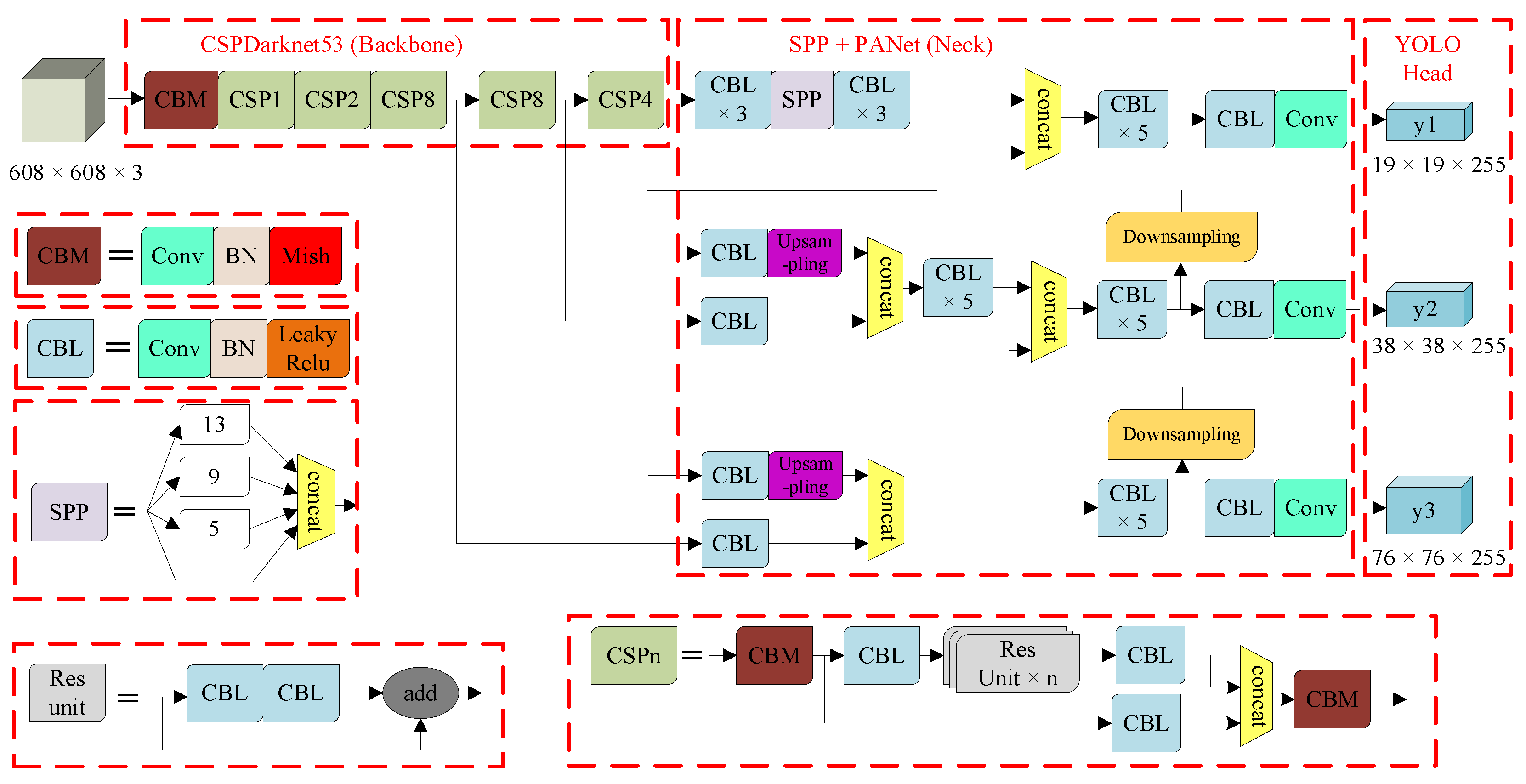
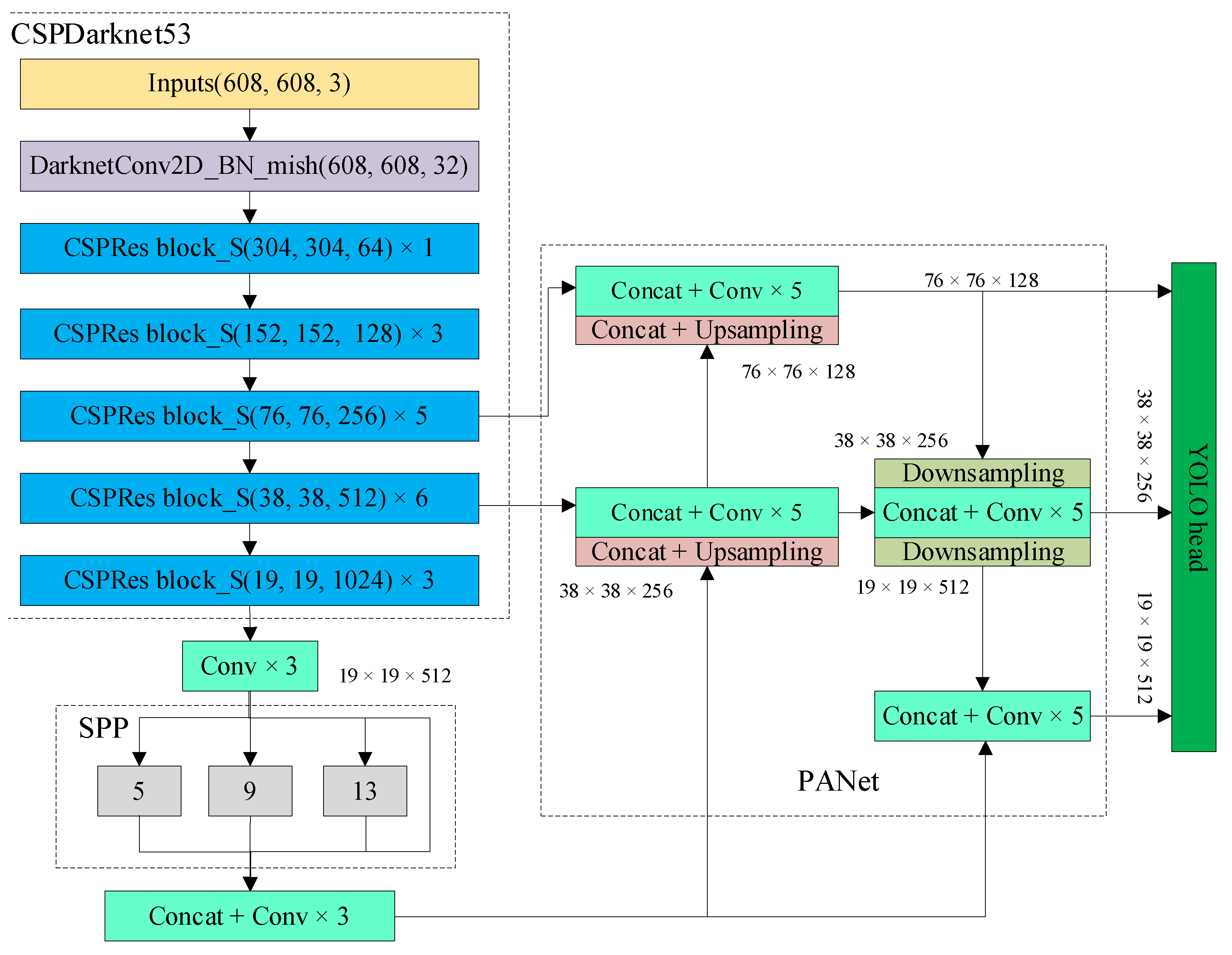
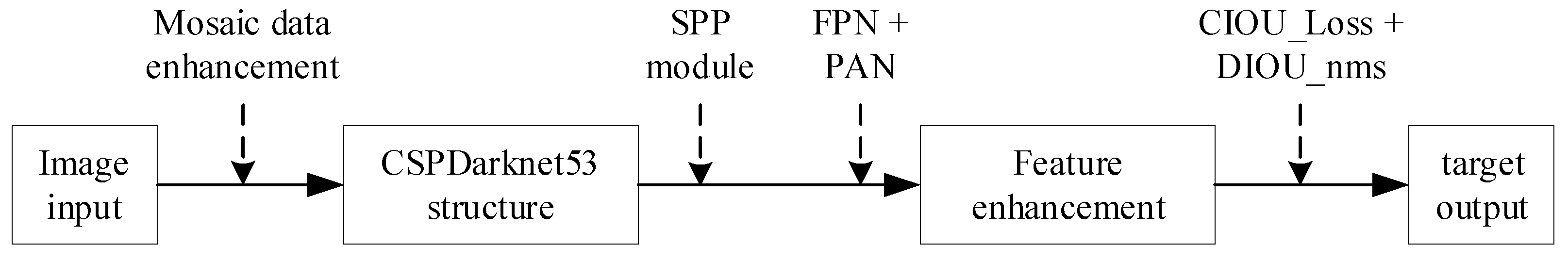
2.1. Target Detection Based on YOLOv4 Algorithm

Aiming at the difficulty of multi-ship detection in complex scenarios, this study is based on the YOLOv4 algorithm to detect and track surface ship targets. The original version of YOLOv1 has many limitations [25]. YOLOv2 improves the shortcomings of the previous generation of low recognition performance and improves the detection speed but has difficulty identifying small targets [26]. YOLOv3 has made small improvements on the basis of the previous generation, using the new Darknet53 architecture as the backbone network, which improves the recognition performance of small objects. YOLOv4 improves the backbone network on the basis of YOLOv3, which improves the detection accuracy and detection speed.
The backbone network of the YOLOv4 algorithm consists of three parts: CSPDarknet53, Mish activation function, and Dropblock. The CSPDarknet53 network is improved on the basis of the Darknet53 network, and its network model structure is shown in Figure 1. CSPDarknet53 enhances the learning ability of CNN, making the model lightweight and maintaining object detection accuracy. CSPDarknet53 is also responsible for feature extraction of images, and finally outputs feature maps of three scales. Mish activation function improves detection accuracy. Dropblock comprehensively upgraded the regularization process of the network, making the detection effect better.
The main frame of the YOLOv4 algorithm is shown in Figure 1. It adds CSP structure and pixel aggregation network (PAN) structure on the basis of the previous generation. The framework of YOLOv4 contains five basic components: ① CBM, the smallest component in the Yolov4 network structure, composed of three activation functions, Conv + Bn + Mish; ② CBL, composed of three activation functions, Conv + Bn + Leaky_Relu; ③ Res unit, the residual structure makes the network construction deeper; ④ CSPX, consists of a convolutional layer and n Res unit modules Concat; and ⑤ SPP, uses the maximum pooling method of {1 × 1, 5 × 5, 9 × 9, 13 × 13} to carry out multi-scale fusion, and effectively strengthens the receiving range of backbone features.

2.2. YOLOv4 Algorithm Improvement

The CSPDarknet53 structure has five consecutive convolution operations. Excessive convolution operations make the structure of CSPDarknet53 more complex, increase the model training time, and reduce the detection speed, and even lead to overfitting of the model after training. At the same time, too many convolution operations will cause the feature information of smaller objects to decrease or even disappear. For multi-ship targets, the small ship target features are lost after multi-layer convolution operations, resulting in the model usually detecting large ships and ignoring small ships. Small ship targets occupy a small number of pixels in the image or a small size in the image when ship targets are crowded, so the detection accuracy and feature size are difficult to balance, resulting in small ship targets in dense distribution to miss detection and low detection accuracy.
To solve the above problems, an improvement of YOLOv4 is proposed in this paper, where the network of feature extraction layer is simplified to obtain more shallow feature information and avoid the disappearance of the small ship target feature, and residual network is used to replace continuous convolution operation to solve the problem of network degradation and gradient disappearance. The input size of images in the YOLOv4 algorithm is {608, 608, 3}. In this paper, the structure of the CSPDarknet53 network is simplified and the network layers are extracted by the feature of lightweight network structure layers. The residual structure of the five-layer network in the feature extraction network of the YOLOv4 algorithm is simplified to {1, 3, 5, 6, 3}, which reduces the number of parameters of the algorithm and simplifies the network structure, preventing the over-fitting of the training model and improving the detection speed. The feature pyramid structure in this paper includes special pyramid pooling (SPP) and pixel aggregation network (PAN) structures, where SPP is the spatial pyramid pooling layer, which aims to increase the receptive field of the network and separate significant contextual features. In addition, in the PAN structure of the NECK part of YOLOv4, five times of residual connection operation is used to replace five times of continuous convolution operation, and finally three feature maps of different scales are generated for prediction. The structure improvement is shown in Figure 2.
In order to obtain more feature information and improve the accuracy of ship target detection in complex situations, a target detector with high accuracy and speed was designed, as shown in Figure 3. Its specific processing flow is as follows: First, the Mosaic data enhancement algorithm is used to enhance the image input. The Mosaic data enhancement algorithm is an improved version of the CutMix data enhancement algorithm, but the CutMix data enhancement algorithm only uses two images for stitching, while the Mosaic data enhancement algorithm uses four images to randomly flip, zoom, crop, change the color gamut, and arrange them for stitching. This improved method can enrich the detection dataset, increase the detection rate of small objects, and improve the robustness of the network. Then, the SPP module is inserted after the CSPDarknet53 network structure, and the FPN + PAN method is used to aggregate parameters before the output layer. Finally, the CIOU_Loss and DIOU_nms method is used for the output layer to perform regression training and prediction frame selection.
The detection process of the algorithm is summarized into three steps: ① Obtain the prediction result through three feature layers; ② decode the prediction result; and ③ obtain the coordinates of the center point of the final bounding box and the width and height of the bounding box, and calculate its position and size, where the calculation formula is:
{ b x = σ ( t x ) + c x b y = σ ( t y ) + c y b w = p w e t w b h = p h e t h P r ( object ) IOU ( b , object ) = σ ( t 0 )
where cx and cy are the number of grids that differ between the upper left corner of the grid where the point is located and the upper left corner of the entire image; tx and ty are the distances of x and y from the center point of the target to the upper left corner, respectively; pw and ph are the side lengths of the a priori box; tw and th are the width and height of the prediction box, respectively; and σ is the activation function, which is between (0, 1).

3. Target Tracking

In this section, the principle of the unscented Kalman filter algorithm (UKF) is analyzed for the nonlinear system of marine ships, the UKF prediction method is used to track the trajectory of multi-ship targets, and the YOLOv4 and UKF prediction algorithms are integrated to realize the detection and tracking of multi-ship targets.

3.1. Target Tracking Method

At present, the commonly used target tracking methods can be divided into two categories: tracking algorithms based on target feature modeling and tracking algorithms based on trajectory prediction. Usually, the tracking algorithms based on target feature modeling need to introduce an appearance feature extraction model, and then use the model to calculate the features of each detected target. Finally, the cosine distance between each target feature is calculated to obtain the target state position. Although this method has high accuracy, it also increases the time consumption, and it is difficult to meet the real-time requirements of multi-ship target tracking in complex situations. Therefore, the tracking algorithms based on trajectory prediction are selected in this paper.
The Kalman filter algorithm is a common method for trajectory prediction. It uses the historical measurement value to predict the target motion state and compare it with the observation model, then updates the state position of the moving target according to the error. Dynamic target tracking based on the Kalman filter algorithm is only applicable to a linear system, although it can track the target quickly and accurately. In order to make up for the defects of the Kalman filter algorithm, some improved algorithms have appeared, including the extended Kalman filter algorithm (EKF) [27] and unscented Kalman filter algorithm (UKF) [28]. EKF transforms the nonlinear problem into a linear Gaussian model, which not only requires a large amount of calculation, but also introduces errors that may lead to filter divergence. Because the UKF algorithm does not have the above problems, this paper uses the UKF algorithm to track the multi-ship targets.

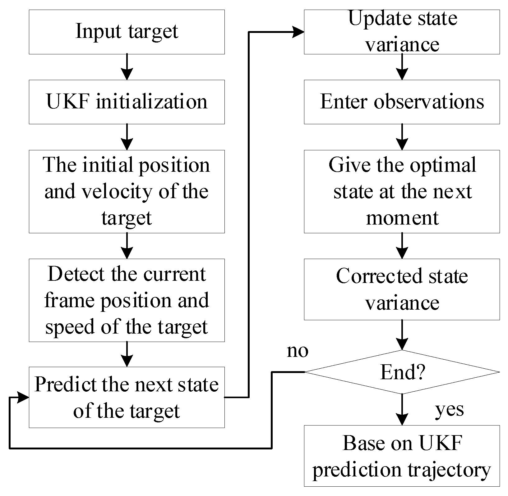
3.2. Target Tracking Based on UKF Algorithm

UKF is aimed at solving the shortcomings of Kalman filtering, and it can be applied to nonlinear systems with higher accuracy and stability by using unscented transform (UT) to process the nonlinear transfer of mean and covariance. In this paper, the mean is an eight-dimensional vector (cx, cy, r, h, vx, vy, vr, vh), which is used to represent the position information of the target in the image, where (cx, cy) is the coordinate of the center point of the bounding box, r is the aspect ratio of the bounding box, h is the height of the bounding box, and vx, vy, vr, and vh are the respective speed change values of the first four quantities, whose initial values are 0. The covariance is an 8 × 8 diagonal matrix, which is used to represent the uncertainty of the target position information. Among them, the smaller the number in the diagonal matrix, the smaller the uncertainty.
The basic principle of UT can be described mathematically as: suppose a nonlinear system y = f ( x ) , where x is an n-dimensional random state vector, and its mean value x ¯ and variance P x , are known. After the UT of Equations (2) and (3), 2 n + 1 sigma points X i and corresponding weights W i can be obtained, then the mean y ¯ i and covariance P y of y can be obtained by Equation (4).
{ X 0 = x ¯ , i = 0 X i = x ¯ + ( ( n + λ ) P x ) i , i = 1 n X i = x ¯ ( ( n + λ ) P x ) i , i = n + 1 2 n
{ W 0 m = λ n + λ W 0 c = λ n + λ + 1 α 2 + β W i m = W i c = λ 2 ( n + λ ) , i = 1 2 n
{ y i = f ( x i ) y ¯ i = i = 0 2 n W i y i P y = i = 0 2 n W i c ( y i y ) ( y i y ) T
In Equation (2), λ = α 2 ( n + k ) n is the scale factor; ( P ) T ( P ) = P and ( P ) i represent the i-th column of the square root of the matrix, that is, ( ( n + λ ) P x ) i is the i-th column of the matrix ( n + λ ) P x . In Equation (3), the superscript m is the mean, the superscript c is the covariance, and the subscript i is the i-th sampling point.
There are three constants, α , β and k in the above formulas. α is the distribution state that determines the sigma points around x ¯ , and its value range is 0 α 1 . The influence of higher-order terms can be reduced by adjusting the size of α , usually taking a smaller value. k is to ensure that the matrix ( n + λ ) P x is a semi-positive definite matrix, usually set at k = 3 n , and if k is negative, the value of k is 0. β is the state distribution parameter used to describe x, and the variance accuracy can be improved by setting β ( β 0 ) ; usually β = 2 is the optimal value in Gaussian distribution.
The UKF algorithm uses the principle of UT to approximate the probability distribution with a fixed number of parameters. It first selects points in the original distribution according to a certain rule, so that the mean and covariance of the selected points are equal to the mean and covariance of the original state distribution. Then, the selected points are substituted into the nonlinear function to obtain the nonlinear function value point set (sigma point set), and then the appropriate weights are selected to estimate the mean and covariance. The nonlinear system considering Gaussian white noise can be represented by Equation (5):
{ X k + 1 = f ( x k , W k ) Z k = h ( x k , V k )
where f and h are the nonlinear state equation function and nonlinear observation equation function, respectively, and W k and V k have covariance matrices Q and R.
The specific steps of the UKF algorithm are as follows:
① Obtain a set of sigma point sets. Assuming that the initial state of the filter is estimated as x ^ 0 | 0 = E ( x 0 ) and the estimated variance is P 0 | 0 = E ( x 0 x ^ 0 | 0 ) ( x 0 x ^ 0 | 0 ) T , according to the above UT principle, the sigma point set is calculated by Equation (6).
X ( k | k ) ( i ) = [ X ^ ( k | k ) X ^ ( k | k ) + ( n + λ ) P ( k | k ) X ^ ( k | k ) ( n + λ ) P ( k | k ) ]
② Make a one-step prediction on the sigma point set. Assuming that the state estimate at time k is x ¯ k and the estimated variance is P k , 2n + 1, sigma sampling points can be obtained from Equation (7) and the corresponding weight W i can be obtained from Equation (3).
X i = X ( k + 1 | k ) ( i ) = f [ k , X ( k | k ) ( i ) ]
where i = 1 , 2 , , 2 n .
③ Compute the mean and covariance. Using the sampling points and corresponding weights of step ②, the mean X ^ ( k + 1 | k ) and covariance P ( k + 1 | k ) of the one-step state prediction can be obtained from Equations (8) and (9).
X ^ ( k + 1 | k ) = i = 0 2 n W i X ( k + 1 | k ) ( i )
P ( k + 1 | k ) = i = 0 2 n W i [ X ^ ( k + 1 | k ) X ( k + 1 | k ) ( i ) ] [ X ^ ( k + 1 | k ) X ( k + 1 | k ) ( i ) ] T + Q
④ Perform another UT according to the one-step state prediction value to obtain a new sigma point set. That is, take the mean X ^ ( k + 1 | k ) and covariance P ( k + 1 | k ) calculated in step ③ as the initial state, and then obtain a new sigma point set by Equation (10).
X ( k + 1 | k ) ( i ) = [ X ^ ( k + 1 | k ) X ^ ( k + 1 | k ) + ( n + λ ) P ( k + 1 | k ) X ^ ( k + 1 | k ) ( n + λ ) P ( k + 1 | k ) ]
⑤ Compute the mean and covariance. Re-substitute the new sigma point set into observation Equation (11) to obtain the predicted observation value, and obtain the predicted mean and covariance of the system through the weighted summation of Equation (12).
Z ( k + 1 | k ) ( i ) = h [ X ( k + 1 | k ) ( i ) ]
{ Z ¯ ( k + 1 | k ) = i = 0 2 n W i Z ( k + 1 | k ) ( i ) P Z k Z k = i = 0 2 n W i [ Z ( k + 1 | k ) ( i ) Z ¯ ( k + 1 | k ) ] [ Z ( k + 1 | k ) ( i ) Z ¯ ( k + 1 | k ) ] T + R P x k Z k = i = 0 2 n W i [ X ( k + 1 | k ) ( i ) Z ¯ ( k + 1 | k ) ] [ Z ( k + 1 | k ) ( i ) Z ¯ ( k + 1 | k ) ] T
Finally, ⑥ calculate the Kalman gain, the state and covariance of the system, and arrive at the prediction. Putting the measured value Z k + 1 at time k + 1 into Equation (13), the state and covariance of gain K k + 1 and time k + 1 can be obtained.
{ K k + 1 = P x k Z k P Z k Z k 1 X ^ ( k + 1 | k + 1 ) = X ^ ( k + 1 | k ) + K k + 1 ( Z k + 1 Z ^ ( k + 1 | k ) ) P ( k + 1 | k + 1 ) = P ( k + 1 | k ) K k + 1 P Z k Z k K k + 1 T
Due to the influence of complex wind, waves, and currents in the ocean, in the video sequence captured by the onboard camera on the unmanned ship, the obstacle target does not move at a uniform speed, but its target position changes in a nonlinear relationship with time. There is even a phenomenon that the video dynamic picture is tilted. In this study, the UKF method is used to predict and track multiple ship targets. The process is shown in Figure 4.
First, the ship target to be predicted and tracked is selected, and the UKF filter is initialized. Secondly, according to the initial position and velocity of the target and the detected target position and velocity of the current frame, the next state value of the target is predicted, and the state variance is updated. Then, the observed value of the next state is input, the optimal state value at the next moment according to the observed value and the predicted value is obtained, and the state variance is corrected. Finally, it is judged whether the target prediction tracking has ended. If it does not end, it will continue to cycle to predict the next state of the target, and if it does end, the target predicted trajectory is output.

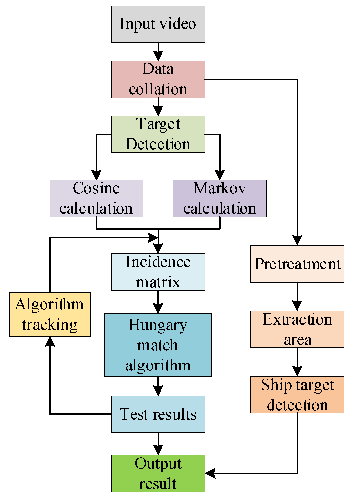
3.3. Fusion Method of Improved YOLOv4 and UKF Algorithm

The fusion idea of improving the YOLOv4 and UKF algorithm is: ① The camera inputs video data. ② The improved YOLOv4 detector is used to complete the ship target detection in the video, and the position information of each target is obtained. ③ The Markov distance and the minimum cosine vector are calculated, and the input is the UKF algorithm result value and the detection value in step ②. ④ The correlation matrix is obtained. ⑤ The Hungarian algorithm and the bipartite graph are used to associate and match each target, and finally the UKF tracker is used to predict the trajectory of the target, and the predicted state position of the target is obtained. Finally, ⑥ updates are made according to the results.
The fusion detection process of the improved YOLOv4 and UKF algorithm is shown in Figure 5.

4. Experiment and Analysis

In this study, the experimental scenes were designed, the experimental platform was built, and the dataset was made. The multi-ship target detection and tracking experiments were carried out in three complex scenes, and the experimental results are evaluated and analyzed.

4.1. Dataset and Parameter Settings

Because the common objects in context (COCO) dataset can solve the problems of target detection and the contextual relationship between targets and precise positioning of two-dimensional targets well, this paper is based on the Microsoft COCO dataset to conduct multi-ship target recognition experiments. In the experiment, the unmanned ship camera was used to shoot video data in the experimental harbor to make the COCO dataset, which consists of 10 video sequences with a total of 4944 frames of images. The image input is enhanced using the Mosaic data enhancement algorithm, it includes image fragments with different lighting scenes, image tilt, target occlusion, etc., so that the actual navigation environment of the ship can be better reflected. The COCO dataset has a certain spatial and temporal coherence because it is filmed by video, so it is necessary to randomly arrange the images in each video sequence to make the training set more random. Then, the number of video frames of each video sequence is divided into training set and test set according to the ratio of 7:3, so as to obtain 3460 frames of images as the training set and 1484 frames of images as the test set.
Because the image resolution of the COCO dataset produced is 1280 × 720, it needs to be converted to a resolution of 608 × 608, suitable for the input of the YOLOv4 model, and the xml format annotation information provided by the dataset is converted into a YOLOv4 format txt file. After the image is reduced to a suitable size, the model input layer size is set to (608, 608, 3). Since the obstacles captured in the video are only ship-type obstacles, the model classification category is set to three categories: sky, water surface, and ship, and at the same time, the target area is flipped, translated, etc., to enhance the training data. The configurations of other training parameters are as follows: the image input amount is 16 and the subdivision is set to 64 in each iteration of training; the momentum and weight decay coefficients are set to 0.9 and 0.0005, respectively; the learning rate and its control parameters are set to 0.001 and 1000, respectively; the maximum number of iterations is 6000; the learning rate change step size is 4800, 5400.

4.2. Experimental Environment

This study was conducted in TensorFlow 2.2.0 (TensorFlow is developed and maintained by Google brain, the Google AI team), a deep learning environment under Windows 10, on a server with anaconda 3.0 and CUDA10.0. The server has an NVIDIA 2060 super GPU and Intel Xeon Gold 5218 CPU.
Considering the complex navigation conditions of ships at sea, the following three complex scenarios were selected for ship target detection and tracking: (1) multi-ship target scenarios with large differences in ship size; (2) scenario with background interference (the background can be shore buildings and rainy and foggy weather); (3) scenario with tilted image (the camera shake causes the video screen to tilt 5°~15°). The specific experimental environment is mainly based on the actual ship navigation environment, and the laboratory scene ship navigation environment is supplemented. The experimental site includes the laboratory pool and the real harbor pool. The specific experimental environment is mainly based on the actual harbor pool, supplemented by the laboratory pool.

4.3. Target Detection Results

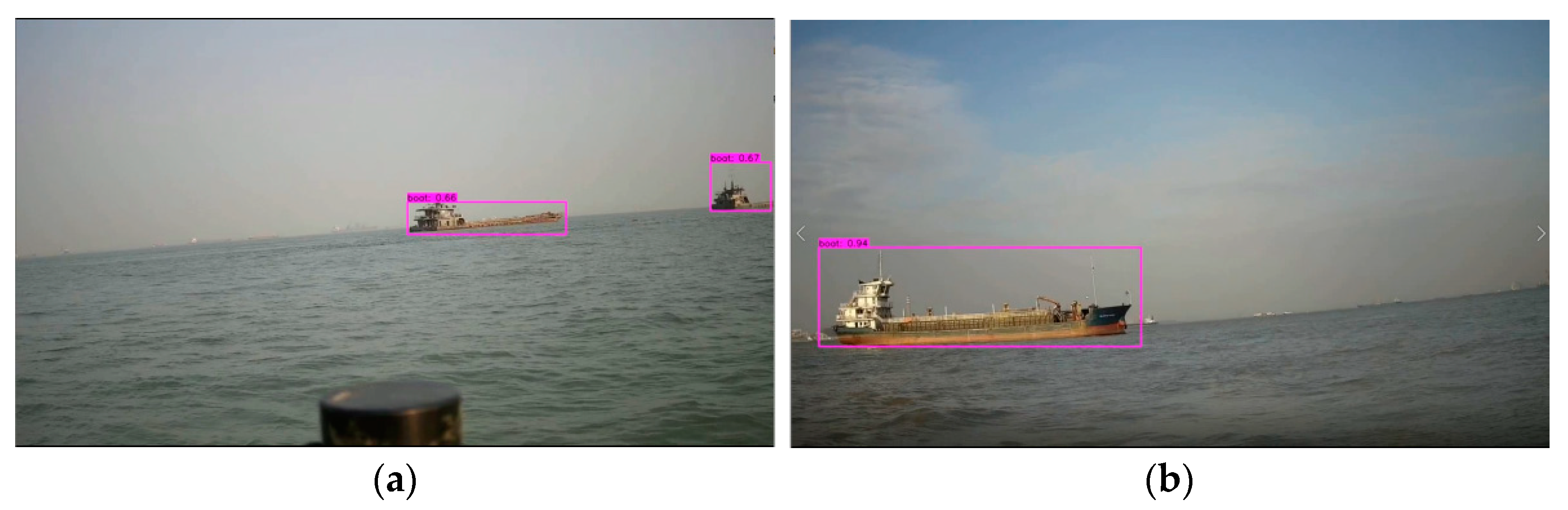
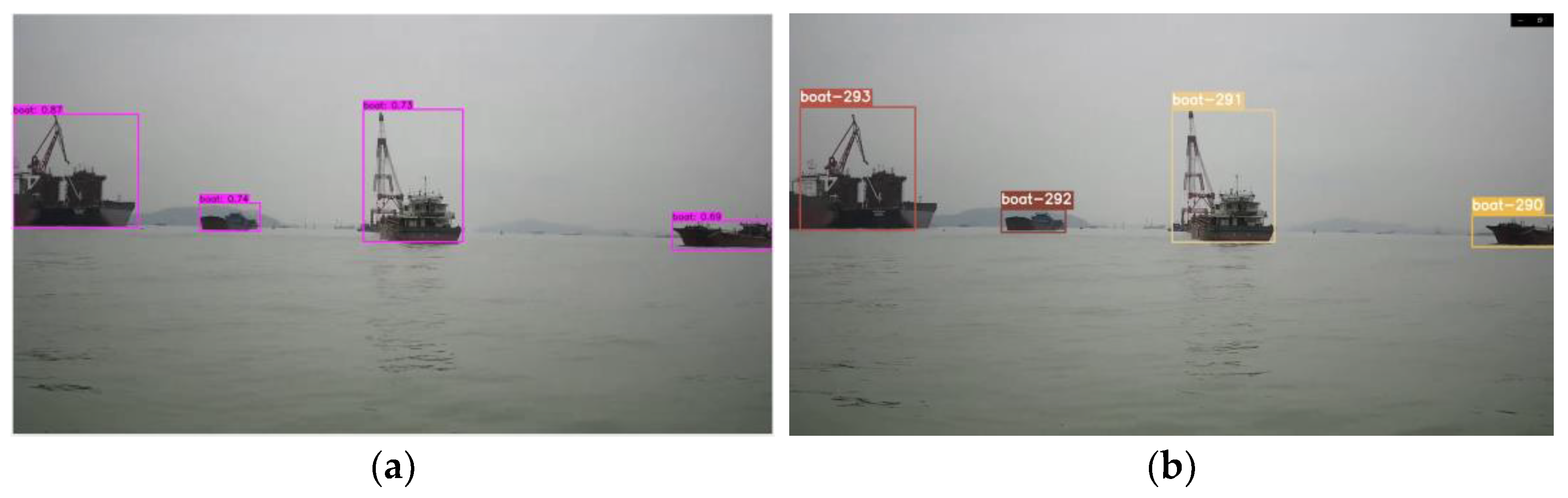
4.3.1. Target Detection with Large Difference in Ship Size

In order to verify the robustness and accuracy of the algorithm in this study, this paper uses the video data captured by the ship-borne camera to conduct a multi-ship target recognition experiment. This paper simplifies the feature extraction layer network, reduces the number of convolution operations, avoids the loss of small target features in the detected image due to overfitting, and improves the detection accuracy of small ship targets that occupy a small number of pixels in the image. The recognition results are shown in Figure 6. In the case of a scene with a huge difference in the size of multiple ships, each ship target can still be detected, and the ship can be accurately marked using the bounding box. The results show that the algorithm in this paper can effectively solve the problem of missed detection of small ships. In addition, it can be seen from the figure that the detection confidence of the difficult-to-detect small ship target is about 0.8, even as high as 0.95, which fully shows the effectiveness of this algorithm for small ship target detection.

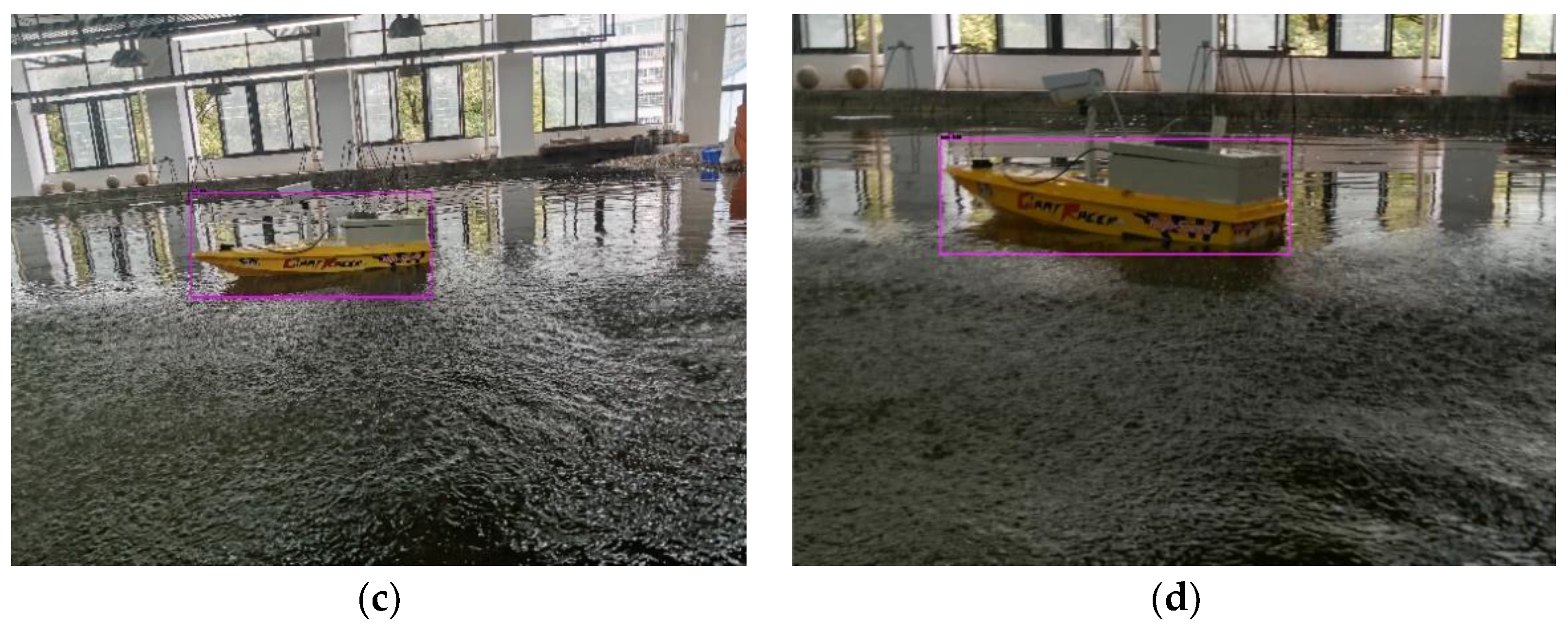
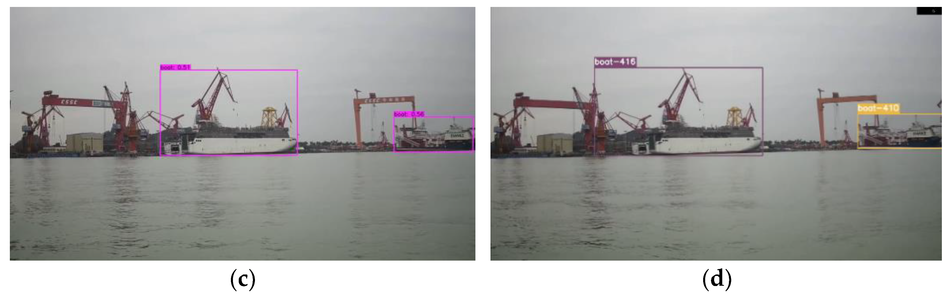
4.3.2. Target Detection with Background Interference

When the color and appearance of the shore building and the detected ship are similar, the YOLO algorithm usually judges the shore building as the ship target or part of the ship, resulting in loss of detection or inaccurate positioning of the actual ship target. In addition, rain and fog reduce visibility, or in backlight scenarios, result in weakened ship characteristics and interference with ship target recognition accuracy. Referring to the sea and land segmentation method of synthetic aperture radar ship detection, in the actual detection, the method of coastline feature segmentation is used to segment the sea and air. The interference targets on the shore can be separated, the number of bounding boxes can be reduced, and the detection time can be saved.
Figure 7 shows the identification results of ship targets under the actual harbor, and the ship can be identified when the buildings on the shore are similar in appearance to the ship. The experimental results show that the coastline feature segmentation eliminates the interference of coastal houses to a large extent, and significantly improves the accuracy of ship identification. In addition, it can be seen from the figure that the detection confidence of nearby ships is higher than that of distant ships, but when the size of the ship and the building on the shore are similar, the detection confidence will decrease.
In this study, image fragments under different lighting scenes are added to the dataset, and the image input is enhanced by the Mosaic data enhancement method at the input end to enhance ship features in complex situations. In rainy day and backlight scenarios simulated in the laboratory pool, ship target recognition results are shown in Figure 8. The results show that the detection effect is remarkable in background interference, backlight, and rainy weather.

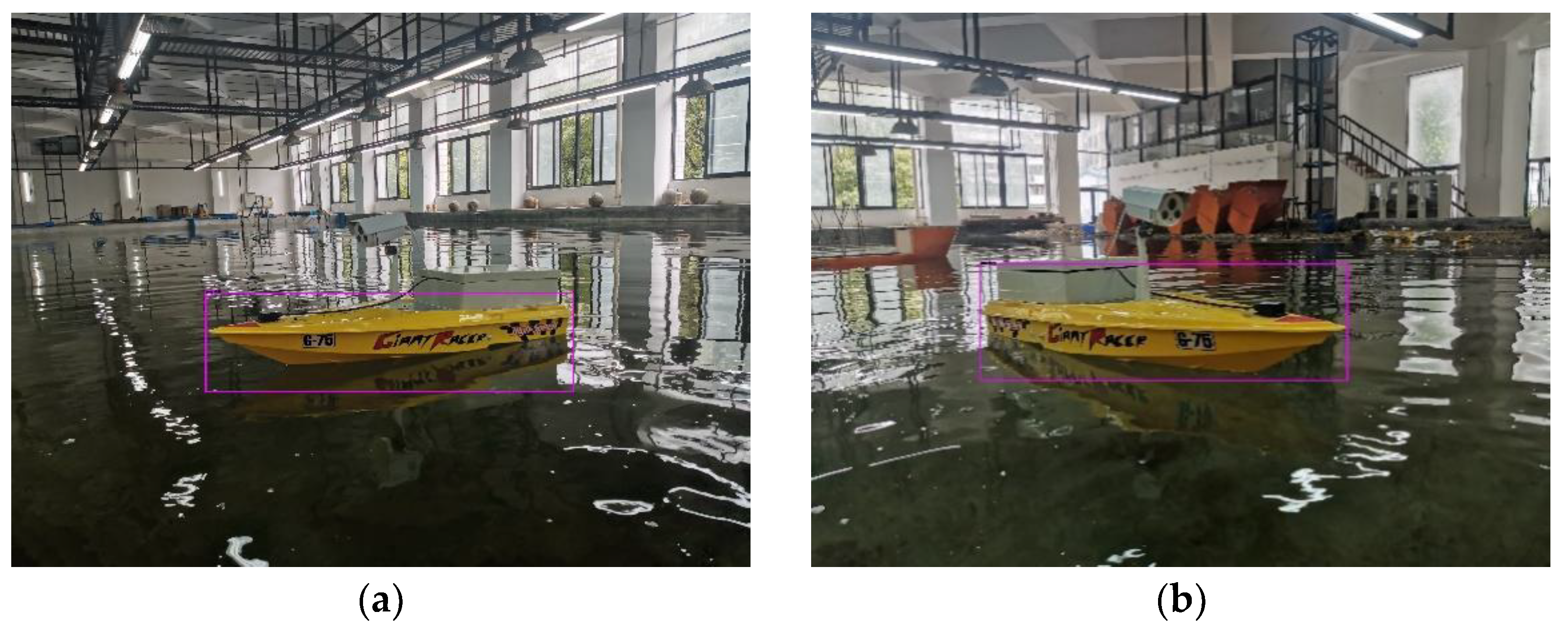
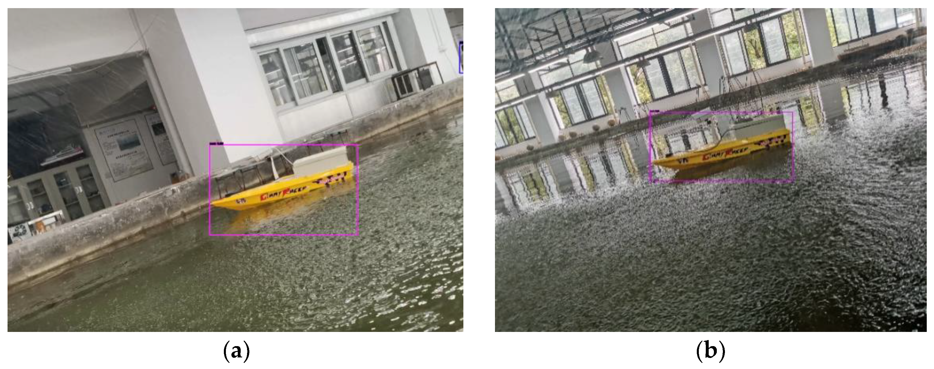
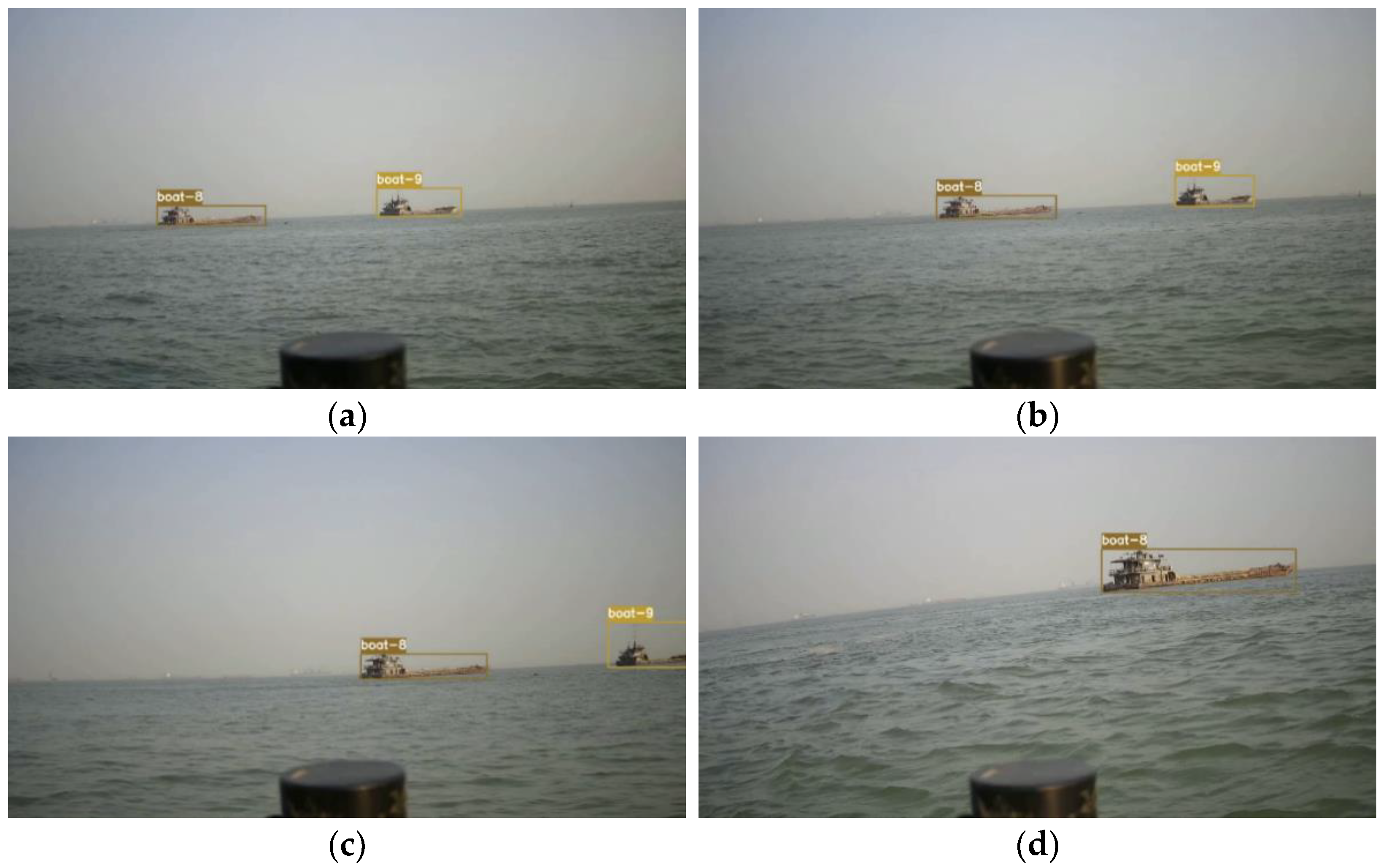
4.3.3. Target Detection of Tilted Images

As a popular research ship type at present, unmanned ships are small in size, are easily affected by wind and waves during sailing, and shake slightly, which leads to the tilt of the picture taken by the unmanned ship camera and makes the detection of ship targets missed. This study addresses this problem by adding skewed image segments to the dataset. The recognition results of the images taken by the unmanned ships in the actual harbor pool by this research algorithm are shown in Figure 9, and the ship target recognition results in the laboratory pool are shown in Figure 10. The results show that the algorithm model can accurately locate and detect ship targets in oblique images. In addition, the inclination angle of the laboratory pool shooting picture is as high as 23°, which is 4.6 times the inclination angle of the actual sailing.

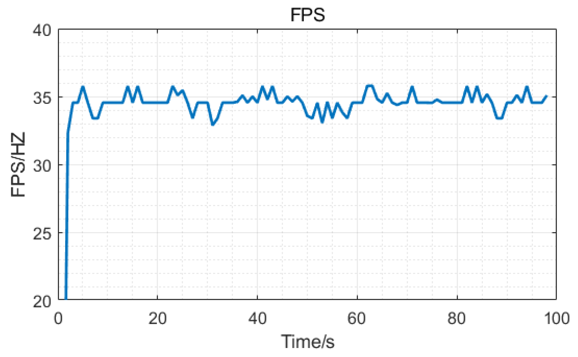
4.3.4. Evaluation of Results

The evaluation indicators of the target detection results in this paper are average precision (AP) and frame per second (FPS). AP is an indicator used to measure the accuracy of the prediction box position and category, and FPS is an indicator used to evaluate the speed of image processing and the real-time performance of the algorithm. Figure 11 shows the precision and recall curve (P-R curve) of the ship target detection method of this paper. As can be seen from the figure, the P-R curve gradually decreases with the increase in the recall rate, and its AP value is calculated as 0.945. When the recall rate reaches 80%, the accuracy rate is still above 90%, and the recall rate can reach 85% without losing the accuracy rate, which indicates that the method has high detection accuracy.
In terms of target detection speed, when the FPS of the algorithm is greater than 24, it is generally considered that it has good real-time performance. Figure 12 shows the FPS during the process of target detection of this paper algorithm. The average FPS reaches 34.5, indicating that the algorithm has excellent real-time performance. Table 1 is the comparison of accuracy and speed performance of different target detection algorithms. As can be seen from the table, the AP value of each algorithm has little difference, but the FPS of our algorithm is the largest. Compared with the LSDM-tiny algorithm proposed by Li Z. [29], the FPS of ours is improved by about 27% while the AP of ours is also slightly better. In addition, compared with the YOLOv4 algorithm, which is combined with channel attention [30], although the AP of ours decreased a little, the FPS increased significantly.

4.4. Target Tracking Results

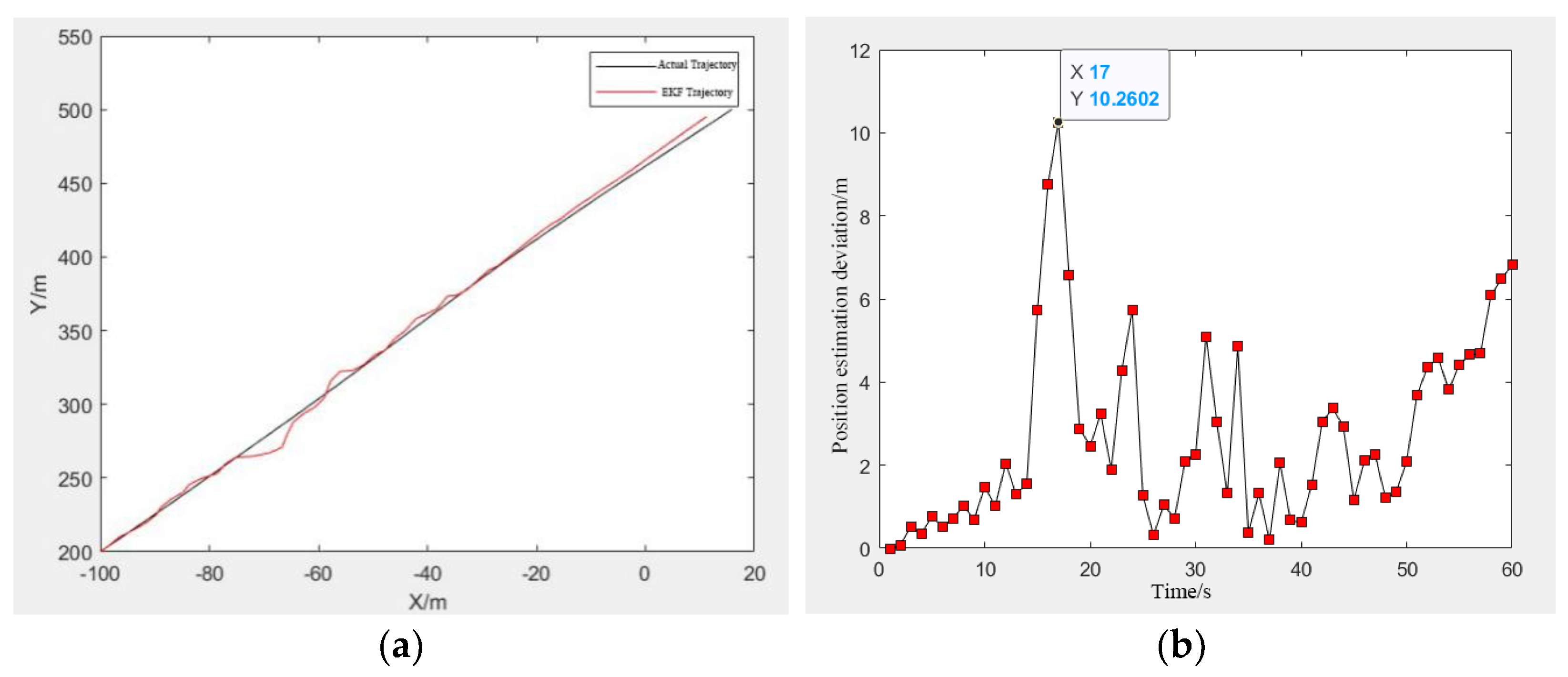
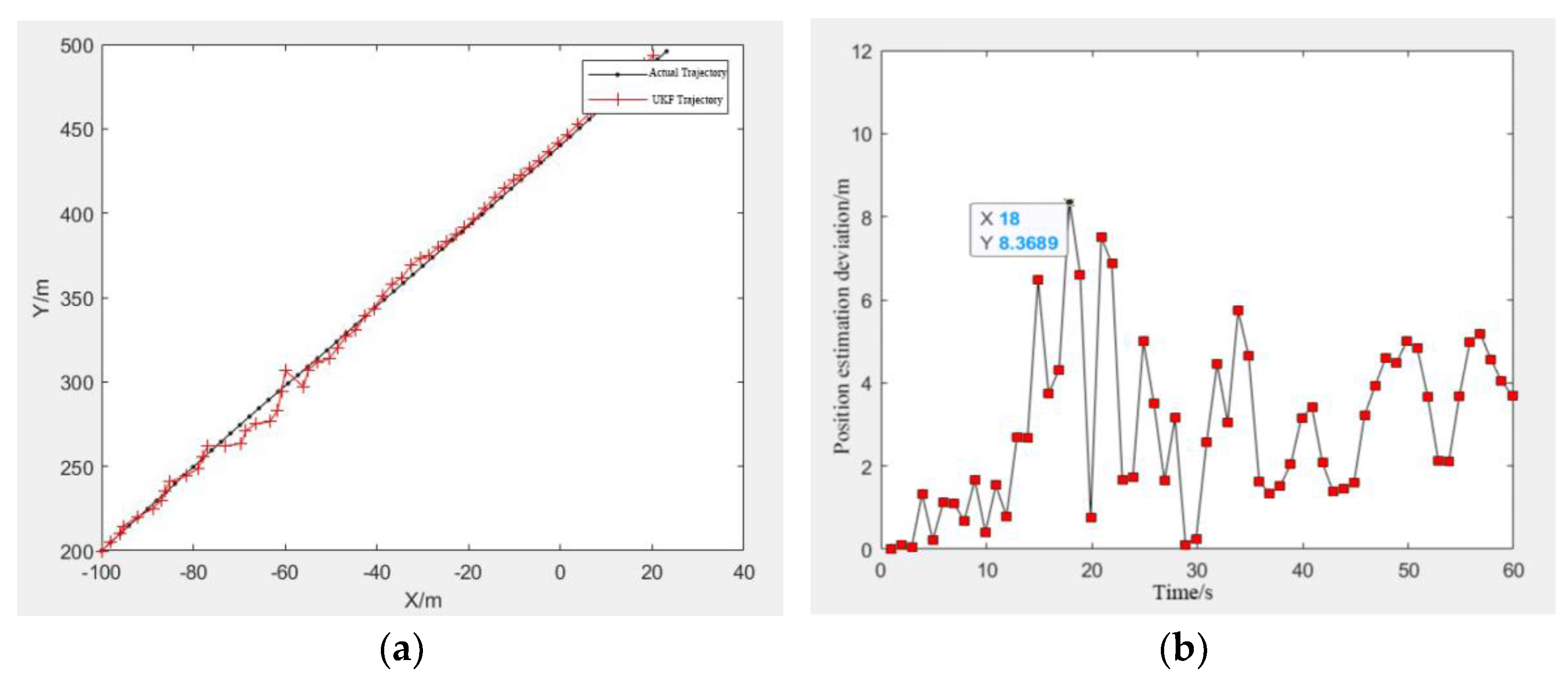
4.4.1. Target Tracking Comparison of EKF and UKF Algorithm

The UKF algorithm in this paper is compared with the EKF algorithm, and the target tracking simulation experiments were completed, where the parameters are set as the same. The initial position of the target ship is set as (−100 m, 200 m) and the speed as (2, 5), that is, the x-axis direction is 2 m/s and the y-axis direction is 5 m/s. The coordinate position of the camera observation point is (200 m, 300 m), and the target ship position is obtained by scanning, where the scanning period T is 1 s, and the sampling number N is 60/T. Finally, the experiment was carried out on a server equipped with a window10 system, where the CPU is Intel Xeon Gold 5218 and the GPU is NVIDIA 2060 super.
The target tracking based on EKF algorithm is shown in Figure 13, where Figure 13a is the comparison between the predicted trajectory based on EKF and the actual target trajectory, and Figure 13b is the deviation of the target position estimation based on EKF. It can be seen from Figure 13b that the maximum error of the estimated target position of EKF is about 10.26 m, and it can be seen from Figure 13a that the error tends to increase at the end of the curve. The target tracking based on the UKF algorithm is shown in Figure 14. It can be seen that the maximum error of the estimated target position of UKF is about 8.37 m, and there is no problem of increasing error at the end of the curve. In the later stage of target ship tracking, the deviation of the UKF algorithm is also smaller than that of the EKF algorithm, indicating that the UKF algorithm has better performance for ship target tracking.
Therefore, compared with the EKF algorithm, the UKF algorithm after UT has better accuracy and stability. It can handle non-derivable nonlinear functions without solving the Jacobian matrix, which makes it easier to implement and can be better applied to ship target tracking.

4.4.2. Target Detection and Tracking of Improved YOLOv4 and UKF Algorithm

The experimental research of ship target detection and tracking based on videos was carried out. In the videos, the ship targets are detected by the improved YOLOv4 algorithm, the detection results are surrounded by bounding boxes, and then the UKF algorithm is used to track the target of the detection results. The information contained in the bounding box of the tracking results includes the target category and the tracking ID number of the ships.
Figure 15 shows some screenshots of the detection and tracking results of a video captured by an unmanned ship using the improved YOLOv4 and UKF algorithms. Figure 16 is some random screenshots of the detection and tracking results of another video. It can be seen from the experiments that during the whole tracking process, the two ships were marked as “boat8” and “boat9”, and the target was not lost in the case of screen shaking. The algorithms proposed in this paper can realize the ship target detection and tracking function well, without missing detection and false detection, and also have good real-time performance.

4.4.3. Evaluation of Results

The evaluation indicators of the target tracking results in this paper are the multiple object tracking accuracy (MOTA) and the multiple object tracking precision (MOTP).
MOTA is used to evaluate the accuracy of tracking, which mainly focuses on the number of errors in tracking. The fewer the tracking errors, the higher the MOTA value, which means better tracking accuracy. Its calculation formula is as follows:
MOTA = 1 f n + f p + i d s w g t
where fn is the number of missed detected targets, fp is the number of falsely detected targets, idsw is the number of falsely matched targets, and gt is the total number of targets in the entire tracking process.
MOTP is used to evaluate the precision of tracking, which mainly focuses on the distance between the target tracking bounding box and the detection bounding box. The smaller the distance, the higher the MOTP value, which means the more precise the tracking and positioning. Its calculation formula is as follows:
MOTP = i , t d t i t c t
where d t i is the Intersection over Union (IoU) between the detection frame of the t-th frame detecting the i-th target and the real frame, and c t is the number of matches in the t-th frame.
Table 2 compares the evaluation indicators between the algorithm of this paper and other algorithms. Among other algorithms, the M3C algorithms proposed by Qiao D. [31] uses multi-model and multi-cues to track the unmanned ships, which has the best performance among them. However, compared with M3C, our algorithm achieves better results, in which MOTA is increased by about 5%. The result shows that the algorithm in this paper has good accuracy of multi-ship target tracking and satisfactory performance.

5. Conclusions

Aiming at the problem that multi-ship target detection and tracking based on cameras is difficult to meet the accuracy and speed requirements at the same time in some complex scenes, a detection and tracking method combining improved YOLOv4 and UKF algorithm is proposed. The structure of the detector was simplified, the ship characteristic data were enhanced, the nonlinear target tracking model was constructed, and target detection and tracking experiments were carried out in many scenes with large differences in ship sizes, strong background interference, tilted images, backlight, insufficient illumination, and rain. The detection and tracking accuracy and real-time performance of different algorithms were compared and analyzed, and the following conclusions were obtained:
(1) The improved YOLOv4 algorithm proposed in this paper simplified the network of the feature extraction layer to obtain more shallow feature information and avoid the disappearance of small ship target features, and uses the residual network to replace the continuous convolution operation to solve the problems of network degradation and gradient disappearance. The comparison experiments in multiple scenes show that the average FPS of this algorithm reaches 34.5. It has better speed performance than other algorithms, and it can better balance the detection accuracy and real-time requirements.
(2) On the basis of target detection, combined with the UKF algorithm, the accurate tracking function of the ship target is realized. Experiments show that the UKF algorithm has better accuracy and stability than the EKF algorithm. It can handle non-derivable nonlinear functions without solving the Jacobian matrix, which makes it easier to implement, has better real-time performance, and can be better applied to ship target tracking.
Finally, (3) in the multi-ship target detection and tracking experiments of multiple scenes based on video, the algorithms proposed in this paper can realize the ship target detection and tracking well, with less missing detection and false detection, and also have good real-time performance. The experiments show that the tracking performance indicators of this algorithm are 76.4% for MOTA and 80.6% for MOTP, which are both better than other algorithms. The above results provide a valuable theoretical reference for the further practical application of the algorithm.
The research in this paper can provide effective information for intelligent ships to avoid other ships in complex scenarios and improve the safety of ship navigation to a certain extent. At present, this research work is only limited to the detection of ship targets, and the detection of other targets needs further research. Underwater target detection and the detection means of fusion cameras and radar or sonar are also future research directions.

Author Contributions

Conceptualization, X.H., Y.C. and B.C.; Formal analysis, Y.C. and B.C.; Funding acquisition, X.H.; Investigation, W.C. and Y.R.; Methodology, X.H., Y.C. and B.C.; Project administration, X.H.; Software, W.C. and Y.R.; Supervision, X.H.; Validation, W.C. and B.C.; Writing—original draft, Y.C. and W.C.; Writing—review and editing, Y.C. and X.H. All authors have read and agreed to the published version of the manuscript.

Funding

This work was supported by the National Key Research and Development Program of China under grant 2019YFB1804204.

Institutional Review Board Statement

All the agencies supported the work.

Informed Consent Statement

All authors agreed to submit the report for publication.

Data Availability Statement

We have obtained all the necessary permission.

Conflicts of Interest

The authors do not report any conflict of interest.

References

  1. Puisa, R.; Lin, L.; Bolbot, V.; Vassalos, D. Unravelling causal factors of maritime incidents and accidents. Saf. Sci. 2018, 110, 124–141. [Google Scholar] [CrossRef] [Green Version]
  2. Goerlandt, F.; Kujala, P. Traffic simulation based ship collision probability modeling. Reliab. Eng. Syst. Saf. 2011, 96, 91–107. [Google Scholar] [CrossRef]
  3. Antão, P.; Guedes Soares, C. Fault-tree models of accident scenarios of RoPax vessels. Int. J. Autom. Comput. 2006, 3, 107–116. [Google Scholar] [CrossRef]
  4. Ernestos, T. Human element and accidents in Greek shipping. J. Navig. 2010, 63, 119–127. [Google Scholar]
  5. Weng, J.; Liao, S.; Wu, B.; Yang, D. Exploring effects of ship traffic characteristics and environmental conditions on ship collision frequency. Marit. Policy Manag. 2020, 47, 523–543. [Google Scholar] [CrossRef]
  6. Kim, D.J.; Kwak, S.Y. Evaluation of human factors in ship accidents in the domestic sea. J. Ergon. Soc. Korea 2011, 30, 87–98. [Google Scholar] [CrossRef] [Green Version]
  7. Shi, J.; Liu, Z. Track Pairs Collision Detection with Applications to Ship Collision Risk Assessment. J. Mar. Sci. Eng. 2022, 10, 216. [Google Scholar] [CrossRef]
  8. Perera, L.P.; Ferrari, V.; Santos, F.P.; Hinostroza, M.A.; Guedes Soares, C. Experimental evaluations on ship autonomous navigation and collision avoidance by intelligent guidance. IEEE J. Ocean. Eng. 2015, 40, 374–387. [Google Scholar] [CrossRef]
  9. Statheros, T.; Howells, G.; Maier, K.M. Autonomous ship collision avoidance navigation concepts, technologies and techniques. J. Navig. 2008, 61, 129–142. [Google Scholar] [CrossRef] [Green Version]
  10. Felski, A.; Zwolak, K. The ocean-going autonomous ship-Challenges and threats. J. Mar. Sci. Eng. 2020, 8, 41. [Google Scholar] [CrossRef] [Green Version]
  11. Levander, O. Autonomous ships on the high seas. IEEE Spectr. 2017, 54, 26–31. [Google Scholar] [CrossRef]
  12. Chen, Y.; Hong, X.; Chen, W.; Wang, H.; Fan, T. Experimental Research on Overwater and Underwater Visual Image Stitching and Fusion Technology of Offshore Operation and Maintenance of Unmanned Ship. J. Mar. Sci. Eng. 2022, 10, 747. [Google Scholar] [CrossRef]
  13. Bhanu, B. Automatic target recognition: State of the art survey. IEEE Trans. Aerosp. Electron. Syst. 1986, 22, 364–379. [Google Scholar] [CrossRef]
  14. Johansen, T.A.; Perez, T.; Cristofaro, A. Ship collision avoidance and COLREGS compliance using simulation-based control behavior selection with predictive hazard assessment. IEEE Trans. Intell. Transp. Syst. 2016, 17, 3407–3422. [Google Scholar] [CrossRef] [Green Version]
  15. Chen, Z.; Li, B.; Tian, L.F.; Chao, D. Automatic detection and tracking of ship based on mean shift in corrected video sequences. In Proceedings of the ICIVC 2017: 2nd International Conference on Image, Vision and Computing, Chengdu, China, 2–4 June 2017. [Google Scholar]
  16. Bao, X.; Javanbakhti, S.; Zinger, S.; Wijnhoven, R.; De With, P.H.N. Context modeling combined with motion analysis for moving ship detection in port surveillance. J. Electron. Imaging 2013, 22, 041114. [Google Scholar] [CrossRef] [Green Version]
  17. Bloisi, D.D.; Pennisi, A.; Iocchi, L. Background modeling in the maritime domain. Mach. Vision Appl. 2014, 25, 1257–1269. [Google Scholar] [CrossRef]
  18. Saghafi, M.; Javadein, S.; Noorhossein, S.; Khalili, H. Robust ship detection and tracking using modified ViBe and backwash cancellation algorithm. In Proceedings of the CIIT 2012: 2nd International Conference on Computational Intelligence and Information Technology, Chennai, India, 3–4 December 2012. [Google Scholar]
  19. Nie, S.; Jiang, Z.; Zhang, H.; Cai, B.; Yao, Y. Inshore ship detection based on mask R-CNN. In Proceedings of the IGARSS 2018: International Geoscience and Remote Sensing Symposium, Valencia, Spain, 22–27 July 2018. [Google Scholar]
  20. Wang, X.; Liu, J.; Liu, X.; Liu, Z.; Khalaf, O.I.; Ji, J.; Ouyang, Q. Ship feature recognition methods for deep learning in complex marine environments. Complex Intell. Syst. 2022, 8, 1–17. [Google Scholar] [CrossRef]
  21. Feng, H.; Guo, J.; Xu, H.; Ge, S.S. SharpGAN: Dynamic Scene Deblurring Method for Smart Ship Based on Receptive Field Block and Generative Adversarial Networks. Sensors 2021, 21, 3641. [Google Scholar] [CrossRef]
  22. Chen, P.; Li, Y.; Zhou, H.; Liu, B.; Liu, P. Detection of Small Ship Objects Using Anchor Boxes Cluster and Feature Pyramid Network Model for SAR Imagery. J. Mar. Sci. Eng. 2020, 8, 112. [Google Scholar] [CrossRef] [Green Version]
  23. Fu, H.; Song, G.; Wang, Y. Improved YOLOv4 Marine Target Detection Combined with CBAM. Symmetry 2021, 13, 623. [Google Scholar] [CrossRef]
  24. Bouma, H.; De Lange, D.J.J.; Van Den Broek, S.P.; Kemp, R.A.W.; Schwering, P.B.W. Automatic detection of small surface targets with electro-optical sensors in a harbor environment. In Proceedings of the SPIE 2008: The International Society for Optical Engineering, Cardiff, Wales, UK, 15–16 September 2008. [Google Scholar]
  25. Williams, D.P. Fast target detection in synthetic aperture sonar imagery: A new algorithm and large-scale performance analysis. IEEE J. Ocean. Eng. 2015, 40, 71–92. [Google Scholar] [CrossRef]
  26. Berus, L.; Skakun, P.; Rajnovic, D.; Janjatovic, P.; Sidjanin, L.; Ficko, M. Determination of the Grain Size in Single-Phase Materials by Edge Detection and Concatenation. Metals 2020, 10, 1381. [Google Scholar] [CrossRef]
  27. Wu, M.; Sun, J. Extended Kalman Filter Based Moving Object Tracking by Mobile Robot in Unknown Environment. Robot 2010, 32, 334–343. [Google Scholar] [CrossRef]
  28. Grachev, A.N.; Kurbatsky, S.A.; Khomyakov, A.V. Algorithm of Low-Flying Target Tracking in Monopulse Radar Stations Based on an Unscented Kalman Filter. J. Commun. Technol. Electron. 2021, 66, 149–154. [Google Scholar] [CrossRef]
  29. Li, Z.; Zhao, L.; Han, X.; Pan, M. Lightweight Ship Detection Methods Based on YOLOv3 and DenseNet. Math. Probl. Eng. 2020, 2020, 4813183. [Google Scholar] [CrossRef]
  30. Li, A.; Yu, L.; Tian, S. Underwater Biological Detection Based on YOLOv4 Combined with Channel Attention. J. Mar. Sci. Eng. 2022, 10, 469. [Google Scholar] [CrossRef]
  31. Qiao, D.; Liu, G.; Zhang, J.; Zhang, Q.; Wu, G.; Dong, F. M3C: Multimodel-and-Multicue-Based Tracking by Detection of Surrounding Vessels in Maritime Environment for USV. Electronics 2019, 8, 723. [Google Scholar] [CrossRef] [Green Version]
Figure 1. The structure of the original YOLOv4.
Jmse 10 00978 g001
Figure 2. The structure of the improved YOLOv4.
Jmse 10 00978 g002
Figure 3. Detection scheme for enhanced object feature.
Jmse 10 00978 g003
Figure 4. Target tracking process based on UKF algorithm.
Jmse 10 00978 g004
Figure 5. The fusion detection process of the improved YOLOv4 and UKF algorithm.
Jmse 10 00978 g005
Figure 6. Target detection results of multiple ships with large difference in ship size in actual scenes. (a) Small ships next to the large ship. (b) Remote small ship detection. (c) Large ships and small ships are intertwined. (d) Multiple distant ship target detection.
Jmse 10 00978 g006
Figure 7. Target detection results with background interference in actual scenes. (a) Ship target detection under the interference of coastal buildings. (b) Ship target detection under the interference of shore equipment.
Jmse 10 00978 g007
Figure 8. Target detection results under background interference in experimental pool. (a) Ship target detection under the background of backlight. (b) Ship target detection under backlight and object interference. (c) Ship target detection under backlight and simulated rain. (d) Ship target detection under simulated rain and insufficient illumination.
Jmse 10 00978 g008aJmse 10 00978 g008b
Figure 9. Target detection results of tilted images in actual scenes. (a) Tilted images 1 in actual scenes. (b) Tilted images 2 in actual scenes.
Jmse 10 00978 g009
Figure 10. Target detection results of tilted images in experimental pool. (a) Tilted images 1 in experimental pool. (b) Tilted images 2 in experimental pool.
Jmse 10 00978 g010
Figure 11. The precision and recall curve of target detection of this paper algorithm.
Jmse 10 00978 g011
Figure 12. The FPS during the process of target detection of this paper’s algorithm.
Jmse 10 00978 g012
Figure 13. Target tracking result based on EKF algorithm. (a) Predicted trajectory based on EKF. (b) The estimated deviation.
Jmse 10 00978 g013
Figure 14. Target tracking result based on UKF algorithm. (a) Predicted trajectory based on UKF. (b) The estimated deviation.
Jmse 10 00978 g014
Figure 15. Target detection and tracking result 1 of improved YOLOv4 and UKF algorithm. (a) Multi-ship target detection in video. (b) Multi-ship target tracking in video. (c) Multi-ship target detection with shore background interference in video. (d) Multi-ship target tracking with shore background interference in video.
Jmse 10 00978 g015aJmse 10 00978 g015b
Figure 16. Target detection and tracking result 2 of improved YOLOv4 and UKF algorithm. (a) Screenshot at frame 73. (b) Screenshot at frame 254. (c) Screenshot at frame 448. (d) Screenshot at frame 624.
Jmse 10 00978 g016
Table 1. Comparison of accuracy and speed performance of different target detection algorithms.
AlgorithmsAPFPS
YOLOv30.94013.5
YOLOv3-tiny0.88127.5
LSDM-tiny0.93527.1
YOLOv4 (combined with channel attention)0.97615
Ours0.94534.5
Table 2. Comparison of evaluation indicators of different target detection and tracking algorithms.
AlgorithmsMOTA (%)MOTP (%)
KCF70.380.2
SORT59.879.6
M3C72.880.4
Ours76.480.6
Publisher’s Note: MDPI stays neutral with regard to jurisdictional claims in published maps and institutional affiliations.

