Article

Analytical Penetration Solutions of Large-Diameter Open-Ended Piles Subjected to Hammering Loads

1
College of Architecture and Civil Engineering, Wenzhou University, Wenzhou 325035, China
2
School of Civil Engineering, Southeast University, Nanjing 211189, China
3
Key Laboratory of Engineering and Technology for Soft Soil Foundation and Tideland Reclamation of Zhejiang Province, Wenzhou 325035, China
4
Collaborative Innovation Center of Tide and Reclamation and Ecological Protection, Wenzhou 325035, China
5
Zhejiang Engineering Research Center of Disaster Prevention and Mitigation for Coastal Soft Soil Foundation, Wenzhou 325035, China
6
Key Laboratory of C&PC Structures, Ministry of Education, Southeast University, Nanjing 211189, China
7
School of Engineering, Design and Built Environment, Western Sydney University, Sydney 2751, Australia
*
Author to whom correspondence should be addressed.
J. Mar. Sci. Eng. 2022, 10(7), 885; https://doi.org/10.3390/jmse10070885
Submission received: 19 May 2022 / Revised: 24 June 2022 / Accepted: 24 June 2022 / Published: 27 June 2022
(This article belongs to the Special Issue New Challenges in Offshore Geotechnical Engineering Developments)

Abstract

:
This paper proposes the penetration displacement solutions of large-diameter open-ended steel pipe piles (LOSPs) with the diameter exceeding 2 m subjected to hammering load. The ultimate forcing equilibrium relationships between LOSP and soil are analyzed, and the calculated formula for self-sinking depth is derived. Next, a partial differential equation of pile hammering by single blow in soft soil is developed based on wave equation incorporating the kinematic method. A dynamic coefficient of frictional resistance (DCFR) is implemented in the process of derivation, and then the displacement Fourier analytical expression of LOSP under hammering load is presented. The parameters sensitivity of the analytical solution is investigated, and the displacement curve is compared with the numerical result. The new method presented in this paper could be used to assess the penetration development of driven piles under impact loading to predict the punching through or hammer refusal during penetration.

1. Introduction

Large-diameter open-ended steel pipe piles (LOSPs) with diameter exceeding 1 m are often used in offshore engineering and are generally installed by the driving hammers. In terms of driven piles, i.e., LOSP, hammer refusal and punching through may unfortunately occur during driving, and these may result in accidents or failures during installation [1]. Therefore, drivability analysis is implemented in the design stage, and typical drivability analysis methods are usually implemented based on one-dimensional wave theory, such as using the GRLWEAP software [2,3]. During dynamic penetration, the pile generates inertial forces, and the soil is compressed in a way that produces transverse deformation. The stress wave generated by the hammering load is transmitted along the shaft to penetrate the pile into the soil. When it encounters the soil inside the pile, it generates a transverse Poisson effect on the magnitude of the shear stress between the pile and soil [4]. If the difference in impedance between the pile and the soil inside the pile is neglected, and the displacement and deformation compatibility between the pile and the soil are perfectly maintained, the transverse shear wave can also be completely neglected [5]. Therefore, shear waves are commonly neglected in studying the hammering penetration of LOSPs. This kind of ignorance provides an implementable framework for the application of the one-dimensional wave equation during drivability analysis for open-ended piles. However, the theoretical basis of these approaches is the discretisation of the object and the empirical value of the associated dynamical parameters, which often causes systematic errors and consequently inaccurate analysis results [6,7,8,9,10,11,12,13,14]. For open-ended piles, the soil-plugging effect is another key concern, but it tends to occur relatively infrequently for LOSPs dynamically driven into the soft soil due to the inertia forces during driving. Therefore, the focus of the drivability analysis is on the transfer of stress waves along the pile shaft during driving and the resistance of the soil around the pile which is called soil resistance during driving, while the displacement behavior of the pile under hammering load is not the main focus of this study.
On the other hand, load transfer method is a common way to analyze the pile subjected to axial loads [15], which could predict the load-displacement response and ultimate resistance of the pile [16]. Recently, this method has been improved to determine various types of pile [17,18,19,20]. For instance, the University of Western Australia (UWA) and the Norwegian Geotechnical Institute (NGI) have compiled a database of high-quality pile load tests in sandy and clay soils, and it is now known as the “unified” database [21]. Lehane et al. [19,21] used this “unified” load-displacement curve database to calibrate the relationship of load and settlement based on cone penetration test (CPT), which can be used to estimate pile displacements under dynamic axial loads. In addition, Xu et al. [20] indicated a steep decrease in the vertical load-displacement curve in the 1 g model test while driving an open-ended pile in soft soil. When the vertical load, Pt, is applied on the pile top at time t, the response resistances of the pile shaft and pile end are Ps and Pb, respectively [22]. And then, the piles tend to overcome the soil resistance to penetrate downward. Generally, the penetration displacement of the pile can consist of the shaft displacement (ws) and pile end displacement (wb), respectively. If pile compression is not considered under axial load at a given moment, the total displacement of the pile is wt = wb = ws, where wt is the displacement of the pile top. In this situation, the pile is assumed to be rigid (no pile shaft compression occurs), and therefore, at any given moment, the pile tip load Pt is equal to the sum of the loadings transferred to the pile shaft (Ps) and the pile tip (Pb). However, the load-displacement relationship of LOSPs under hammering loads has not been thoroughly discussed.
This paper analyses the forcing limit equilibrium relationships for self-sinking and hammering loads during the installation of the LOSPs. A solution for estimating the self-sinking is proposed. The inertia forces are then introduced to formulate the ultimate equilibrium partial differential equation for the LOSPs under hammering loads in the framework of wave theory. Finally, the Fourier analytic solution for the displacement of the LOSPs under single hammering blow is solved. For LOSPs, the sensitivity of the parameters in the solution expression was investigated and discussed. The calculated displacement curve of LOSP is compared with the result of numerical simulation. This study provides a simplified approach to determine the penetration to provide a simple method for estimating hammer refusal and punching through of LOSPs during driving.

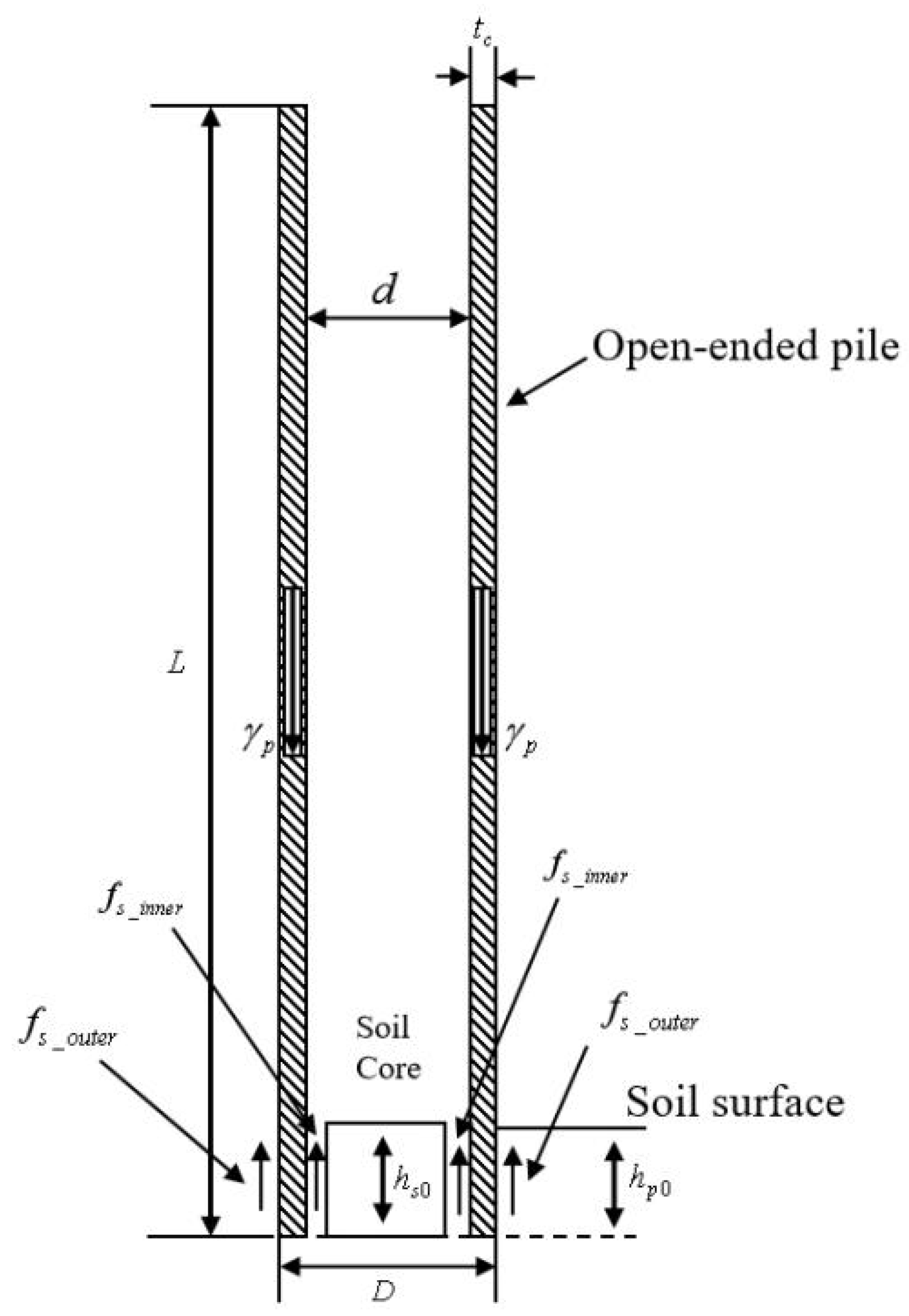
2. Self-Sinking Penetration of LOSPs

At the beginning of installation, the driven pile will sink into the soil for a certain depth due to its own weight until it reaches equilibrium (a process known as self-sinking equilibration). The accurate assessment of the self-sink depth is critical for safe attachment of piles and the following driving operations. Assuming this process does not cause soil plug effect for LOSPs, the force distribution of the pile is shown in Figure 1. When the pile self-sinks until it comes to a standstill, the pile-soil static ultimate equilibrium relationship could be expressed as
f s _ o u t e r π D h p 0 + f s _ i n n e r π d h s 0 + q t i p ( π D 2 4 π d 2 4 ) = γ p ( π D 2 4 π d 2 4 ) L
where f s _ o u t e r and f s _ i n n e r are the shaft frictional resistance of the inside and outside of the LOSPs, respectively; q t i p is the pile tip resistance; γ p is the volume weight of the pile; D and d are the external and internal diameter of the piles, respectively; hp0 and hs0 are the heights of the soil inside and outside the pile after it self-sinks, respectively. By solving the above equation, the self-sinking formula of LOSPs could be obtained as follows:
  h p 0 = ( 1 4 ( γ p L q t i p ) ( D 2 d 2 ) f s _ i n n e r d h s 0 ) / ( f s _ o u t e r D )
Assuming that fs_outer = fs_inner and hp0 = hs0, the above formula could be simplified as
h p 0 = ( 1 4 ( γ p L q t i p ) ( D 2 d 2 ) ) / ( f s _ o u t e r ( D + d ) )
If the wall thickness of the pile is denoted as tc, then D = d + 2tc, which gives
h p 0 = γ p L q t i p 2 f s _ o u t e r t c
Hence, the self-sinking depth can be approximated using a few easier-to-obtained parameters, i.e., wall thickness, pile length, pile volume weight, and the pile tip and shaft resistances. By ignoring the pile tip resistance, a more simplified formula is given as follows:
h p 0 = γ p L 2 f s _ o u t e r t c .

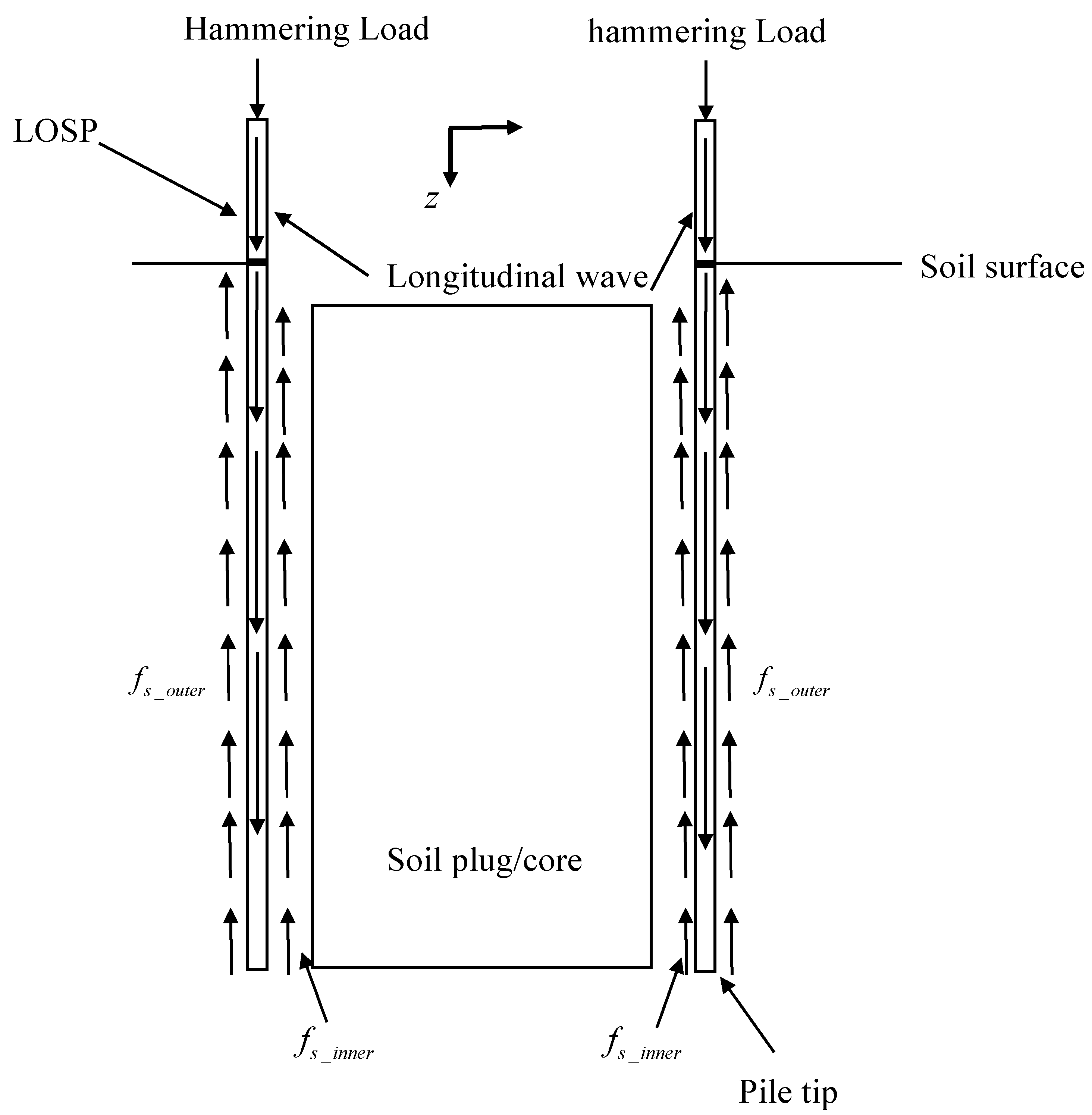
3. Partial Differential Analysis of LOSPs under Hammering Load

When a pile hammer strikes a pile at its top, the stress wave is generated and transmitted longitudinally along the pile body as shown in Figure 2, resulting in the penetration of the pile to the soil. One-dimensional wave equation is a suitable approach to analyze this process. Assuming isotropic property of the pile body, the basic wave-governing equation for a pile subjected to impact loading is listed as follows [23]:
2 u t 2 = c 2 2 u ,
where u(x, y, z) is the displacement in the x-, y-, and z-directions; 2 = 2 / x 2 + 2 / y 2 + 2 / z 2 is the Laplace operator; c is the wave speed if one-dimensional wave propagation is assumed, in which c = λ + 2 G p / ρ for the compressional waves and c = G p / ρ for the shear waves; G p is the shear modulus of pile; ρ is the density of pile; λ = μ E / ( 1 + μ ) ( 1 2 μ ) . The elastic wave velocity is calculated as c = E / ρ . Thus, the above equation can be simplified in the framework of one-dimensional wave theory as follows:
2 u t 2 = c 2 2 u z 2 .
The pile tip resistance is disregarded for the open-ended piles [24], and the dynamic equilibrium differential equation of the pile under a hammering load is presented as follows:
ρ v ( z , t ) t σ z ( z , t ) z = 0
where v(z, t) is the stress wave velocity along the pile shaft, and σ z ( z , t ) is the axial stress.
According to the elasticity theory,
σ z ( z , t ) = E ε z ( z , t )
where ε z ( z , t ) is the axial strain of the pile. Substituting Equation (9) into Equation (8) results in
ρ v ( z , t ) t E ε z ( z , t ) z = 0
In addition, v ( z , t ) = u ( z , t ) / t and ε z ( z , t ) = u ( z , t ) / z , respectively. Therefore, Equation (10) can be expressed as
u 2 ( z , t ) t 2 E u 2 ( z , t ) z 2 = 0 .
The Dirichlet boundary conditions are u ( 0 , t ) = A Δ l l n ( t + 1 ) / l n ( t 0 + 1 ) and u ( L , t ) = B Δ w l n ( t + 1 ) / l n ( t 0 + 1 ) , where Δw is the pile penetration; Δl is the sum of the pile compression and penetration; t0 = L/c, and A and B are constants. The Neumann boundary conditions are u ( z , 0 ) = 0 and u ( z , 0 ) / t = 0 .
When the LOSP is loaded by the hammering loading, the longitudinal waves are applied in the pile body, and the transverse shear waves and longitudinal constrained waves exist in the soil inside the LOSP. To build a simplified analytical model, the effect of transverse shear waves in the soil inside the LOSP is ignored regardless of whether the soil plug effect occurs, at which point only longitudinal compressional stress waves exist in both the pile and the soil inside the pile under the hammering load. During hammering penetration of LOSP with thin wall, the pile tip resistance is a minor contributor to the total resistance. Thus, the tip resistance was ignored in the process of establishing the wave equation of LOSP under a single hammering blow. Alternatively, the physical mechanisms of the LOSP soil under hammering load in the case of no soil plugging and full soil plugging need to be considered separately in the theoretical analysis. As illustrated in Figure 2, under the hammering load, stress waves are transferred along the pile body and the inner and outer sides of the pile are subjected to frictional resistance. The inertial effect of soil could be considered in a dynamic situation. Thus, an inertial factor ξ = a s o i l / g was formulated in this partial differential derivation, where asoil is the acceleration of the soil inside the pile, and this magnitude increases with soil plugging. When full soil plugging occurs, the displacement between the pile and the plug is completely coordinated, and now the inertia factor [25] is ξ = a ( t ) / g , where a(t) is the acceleration of the pile at moment t. Hence, the wave equation that accounts for the shaft resistance is
ρ 2 u ( z , t ) t 2 E 2 u ( z , t ) z 2 = i = 1 n ξ i n n e r i D C F R i n n e r ( i ) f s _ i n n e r _ i π ( D d ) A p L h s i + i = 1 n ξ o u t e r _ i D C F R _ o u t e r ( i ) f s _ o u t e r _ i π D A p L h p _ i ,
where ξ i n n e r _ i and ξ o u t e r _ i are the inertia factors of the i-th soil layer, and the addition of the character i to the parameter symbols is an indication of the i-th layer of the soil; DCFR is the dynamic coefficient of frictional resistance; and Ap is the cross-sectional area of the pile. The right-hand side of the above equation can be calculated as
M = 1 ρ ( i = 1 n ξ i n n e r _ i D C F R _ i n n e r ( i ) f s _ i n n e r _ i π ( D d ) h s _ i A p L + i = 1 n ξ o u t e r _ i D C F R _ o u t e r ( i ) f s _ o u t e r _ i π D h p _ i A p L ) .
Then the partial differential equation is simplified as
2 u ( z , t ) t 2 c 2 2 u ( z , t ) z 2 = M
Thus, the problem is transformed into an inhomogeneity linear partial differential equation with the same boundary conditions as Equation (11). An auxiliary function, w ( z , t ) = ( B Δ w z A Δ l ( z L ) ) l n ( t + 1 ) / ( L l n ( t 0 + 1 ) ) , is introduced which satisfies the Dirichlet boundary conditions.
Introducing the function v ( z , t ) and letting
u ( z , t ) = v ( z , t ) + w ( z , t )
a new format of wave equation can be obtained as
2 v ( z , t ) t 2 c 2 2 v ( z , t ) z 2 = M A Δ l ( z L ) B Δ w z L l n ( t 0 + 1 ) 1 ( t + 1 ) 2
For the Dirichlet boundary, v ( 0 , t ) = v ( L , t ) = 0 . For the Neumann boundary, v ( z , 0 ) = 0 . Thus,
v ( z , 0 ) t = A Δ l ( z L ) B Δ w z L l n ( t 0 + 1 ) .
The problem is then transformed into a problem of mixed inhomogeneity partial differential equations with flush boundary. The Fourier series expression for this problem is
u ( z , t ) = n = 1 ( φ n c o s n c π t L + L n c π ψ n s i n n c π t L + 1 n c π 0 t f n ( τ ) s i n n c π ( t τ ) L d τ ) s i n n π z L
According to the boundary conditions and nonsimultaneous nature of the wave equation, φ n = 0 . Therefore,
ψ n = 2 L l n ( t 0 + 1 ) ( ( A Δ l A Δ l B Δ w n π L ) c o s   n π A Δ l )
and
f n ( t ) = 2 n π ( A Δ l B Δ w l n ( t 0 + 1 ) 1 ( t + 1 ) 2 c o s   n π + ( M + A Δ l l n ( t 0 + 1 ) 1 ( t + 1 ) 2 ) ( 1 c o s   n π ) )
Equations (19) and (20) represent an analytical solution to the displacement of the open-ended pile stress wave under a hammering load, where A and B are constants. When the pile is assumed to be a rigid body, Δl = Δw. The vertical displacement of the pile accompanying stress wave propagation in the presence of resistance inside and outside of the pile can be determined by substituting the corresponding resistance into the analytical solution.

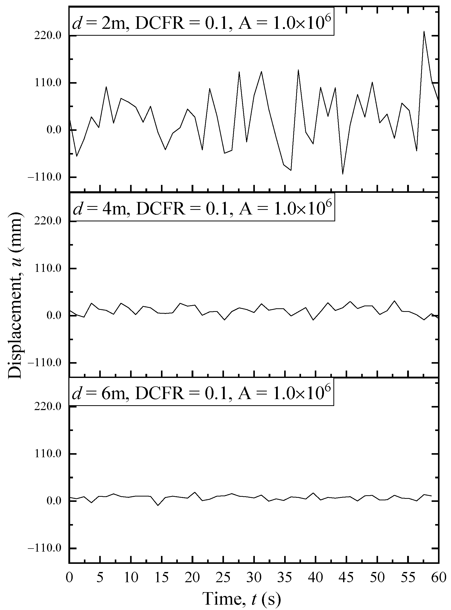
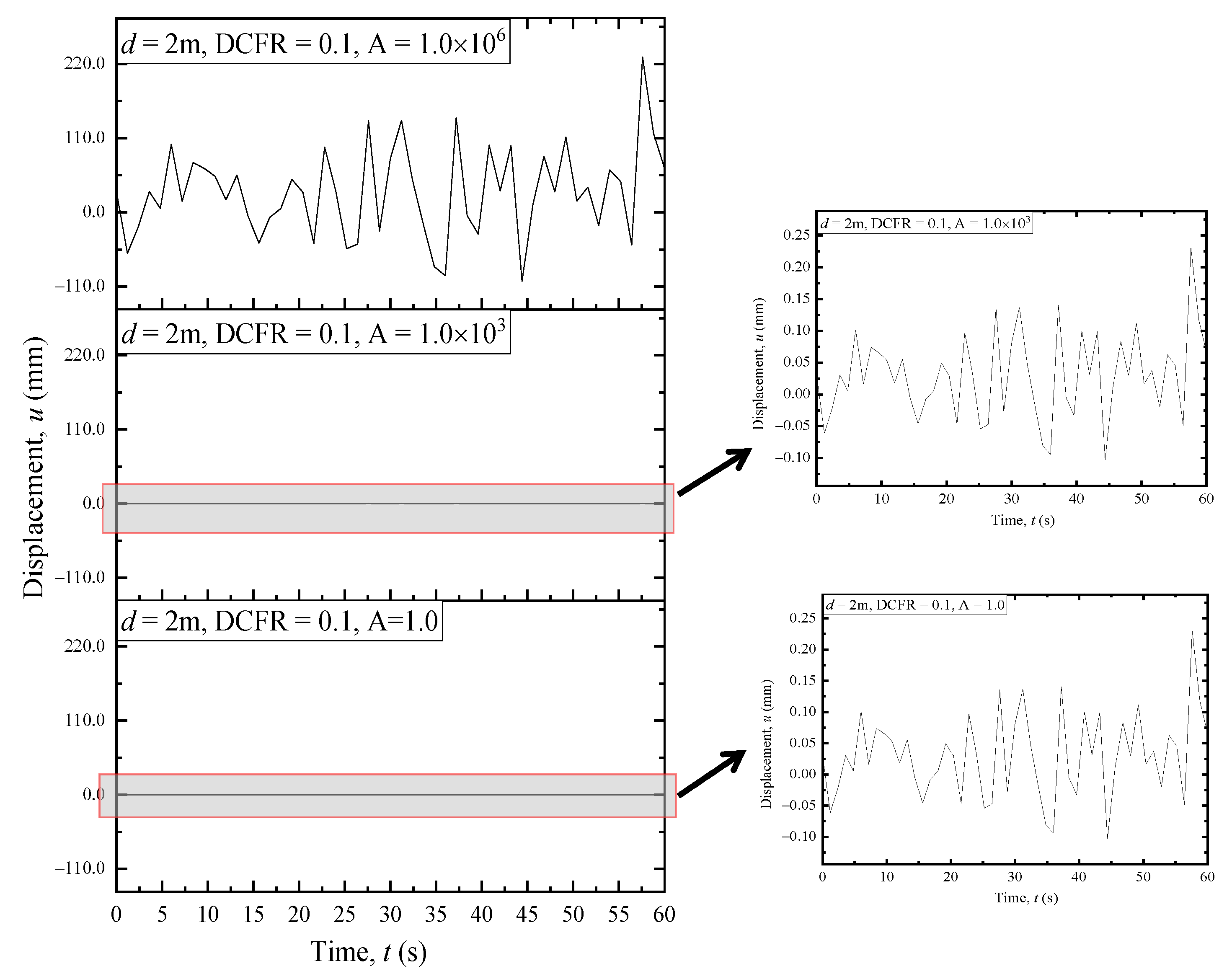
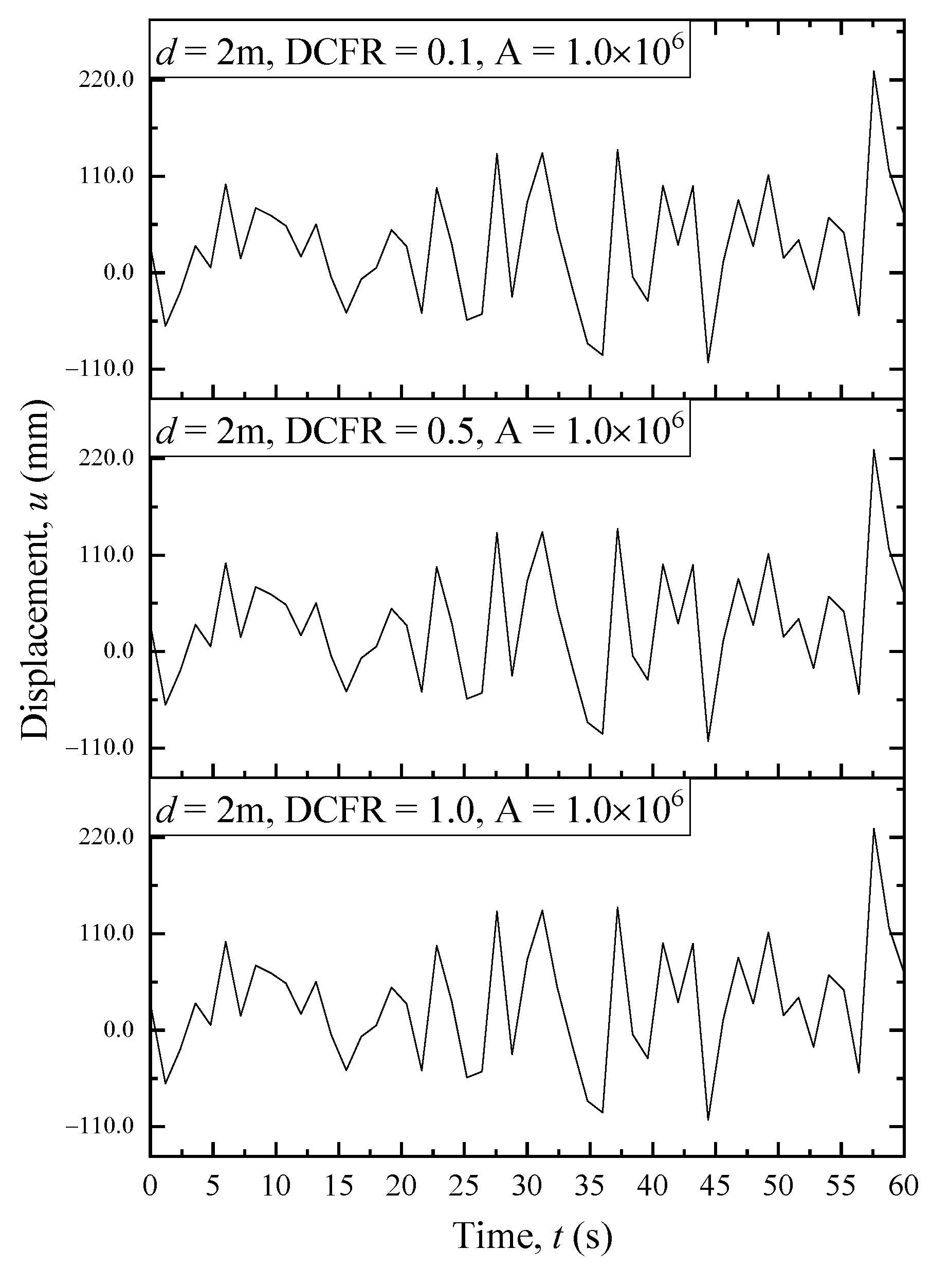
4. Parameters Sensitivity

Assuming that no soil plugging effect occurs during LOSPs driving and the pile is a rigid body, and the soil inside and outside the pile are at the same height. The pile displacement under a hammering load is calculated according to the analytical formula (Equation (18)). Sensitivity analyses of the parameters in Equation (18) are conducted based on LOSPs for internal diameters of 2, 4 and 6 m, separately. The specific calculation parameters are shown in Table 1. The effect of pile compression is not considered during the hammering process. Therefore, the effect of constant B does not need to be considered in Equations (19) and (20). The sensitivity analyses of the proposed displacement equation for LOSPs are shown in Figure 3, Figure 4 and Figure 5.
Although the type of curve oscillation did not vary, the decrease in the magnitude of the constant A resulted in a significant jump down in the scale of the displacement amplitude for LOSP under hammering load (for the case of D = 2 m). The constant A is an empirical parameter and therefore requires more field data to determine the value. As illustrated in Figure 4, the analytical solution is insensitive to the DCFR value. With no soil plugging effect, the value of the DCFR for the LOSP during driving is relatively small and therefore has less influence on the Fourier solution results. The increasing diameter of the pile will reduce the penetration and will also change the shape of the vibration curve under the effect of identical single hammering energy. The other parameters are the same, indicating that for the identical hammering energy, the larger the pile diameter, the smaller the penetration.

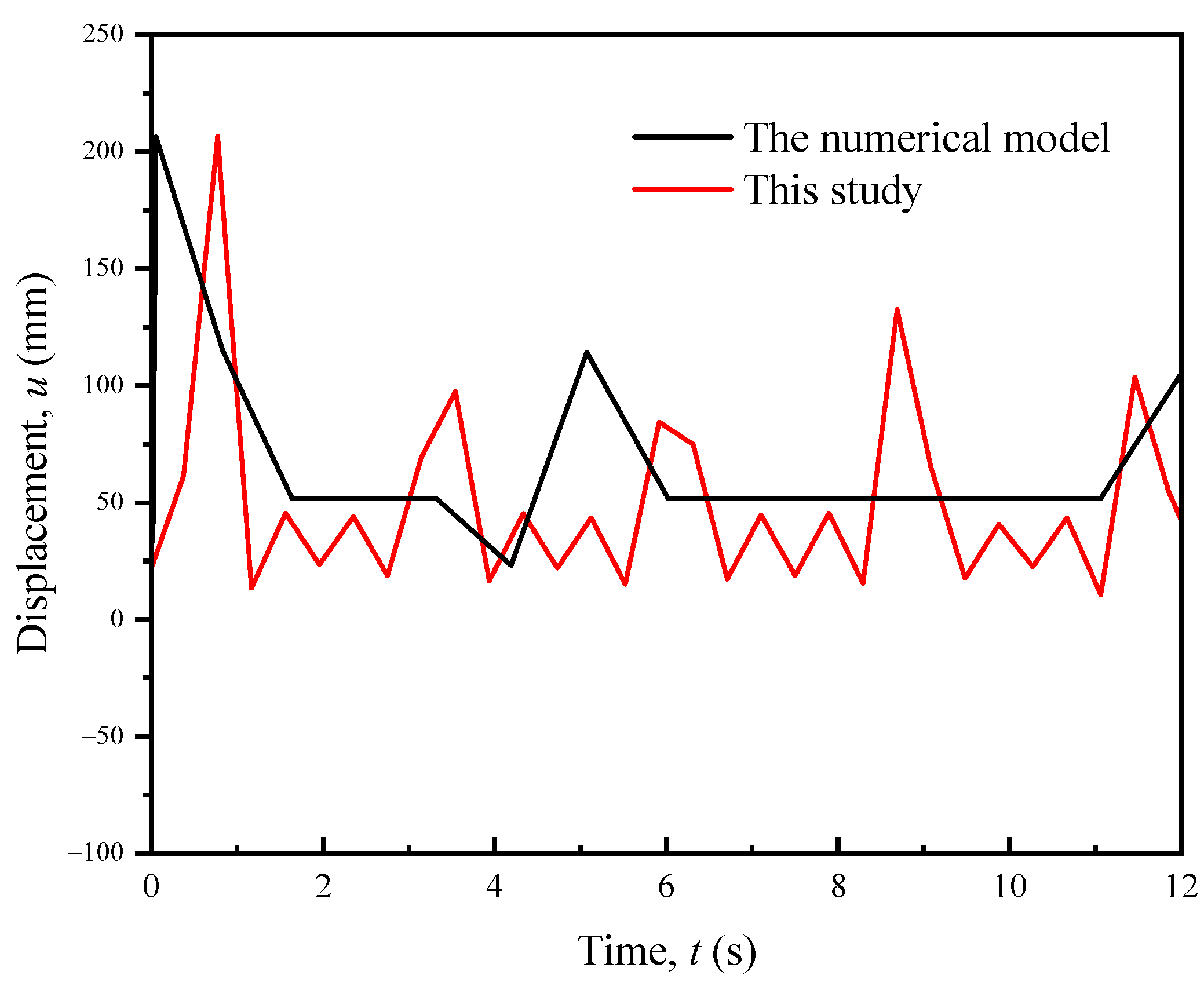
5. Comparison between Numerical Method and Fourier Solution

A finite element (FE) numerical model in ABAQUS/Standard incorporated with the remeshing and interpolation technique with a small strain (RITSS) was built [26], which is carried out on the effective stress analysis for axisymmetric pile impact driven into saturated soil, as shown in Figure 6. The soil model had a width of 10d and height of 2hp (where hp being the target penetration depth) to eliminate the boundary effects. The soil within a distance of 2d longitudinally down from the pile tip and 2d laterally away from the outside pile was finely meshed, and the element size gradually increased away from the pile. In the region of penetration, the minimum size of the element was equal to the wall thickness, and the maximum size was 30 cm. In the far region, the minimum size was 30 cm, and the maximum size was 1.5d. The boundary conditions were free vertically and constrained laterally on the axisymmetric side and constrained in both directions in the far boundary of the model. The element type of this numerical model is CAX4P. The essence of the RITSS technique is to map the variables of the integration points of the deformed elements into the remesh element in the finite element framework [27,28], thus enabling a method for high precision analysis of large deformation problems, i.e., the pile-driving process and spudcan penetration stimulation [29]. The numerical results were compared to the solution curve calculated using Equation (18). The specific parameters values are listed in Table 2. The numerical model was used to obtain the last penetration curve. The comparative analysis is shown in Figure 7, which indicates that the two penetration curves are similar in magnitude. However, the oscillation of the analytical solution curve is more significant for two main reasons. (1) The single hammer load in the numerical model is artificially divided into several steps to achieve convergence. (2) The number of time points for extracting penetration data in the numerical model is not as high as in the analytical solution because of computational cost constraints to reduce the cost of the calculation without affecting the accuracy and overall trend of the displacement curve. In fact, the first displacement peak of the numerical and theoretical curves is essentially the pile penetration, as the theoretical results do not take into account the rebound of the stress wave from the pile bottom and the corresponding resistance of the soil to the pile kickback, which is why the larger displacement fluctuations of the pile occur after the first displacement peak in the figure. In general, the theoretical Equation (18) can be used for rigid pile displacement prediction under one blow. Considering the transmission of stress waves along the pile body during driving, the curves of the first 2 s in the figure are the focus of interest.

6. Conclusions

The LOSPs are widely used in offshore engineering and their driveability analysis has been one of the focuses among the academia and industry. This study proposes a simple approach to calculate the self-sinking depth of LOSPs under self-weight. The concepts of inertia force and inertia factor are employed based on the one-dimensional wave theory to develop a partial differential equation considering the shaft resistance. Further, a Fourier solution for the displacement of the open-ended pile under one blow strike is proposed, and a parametric sensitivity analysis is carried out for the application of the equation in LOSPs. The analytical solution is compared with the numerical result to confirm the validity of the proposed methodology. The results of this study indicate that the simple calculation approach has the potential for predicting the condition of hammer refusal or punching through under single hammer blow for LOSPs driven in offshore soft soil. It should be noted that when LOSP is driven into soft soils, full soil plugging rarely occurs. If it occurs, the acceleration of the soil within the pile should be aligned with the pile during the calculation. With the proposed displacement calculation method for LOSP with a single hammer, the maximum downward displacement in the curve can be considered as the penetration of the single hammer, and the displacement curve of LOSP during the whole driving process can be determined by accumulating and iterating the displacements of the single hammer.

Author Contributions

Conceptualization, W.Q. and G.D.; methodology, W.Q.; software, W.Q.; validation, W.Q.; formal analysis, W.Q.; investigation, W.Q.; resources, G.D. and W.Q.; data curation, W.Q.; writing—original draft preparation, W.Q. and X.L.; writing—review and editing, W.Q., X.L. and P.H.; visualization, W.Q. and X.L.; supervision, G.D. and W.Q.; project administration, G.D. and W.Q.; funding acquisition, W.Q. and G.D. All authors have read and agreed to the published version of the manuscript.

Funding

This research was funded by the National Natural Science Foundation of China (grant number: 52008318(granter: W.Q.) and 51878160(granter: G.D.), Education Department of Zhejiang Province (grant number: Y202146717(head of funding: W.Q.; participant: X.L.)), and by the Graduate Innovation Fund Project of Wenzhou University (grant number: 316202101061(head of funding: W.Q.; participant: X.L.)).

Data Availability Statement

The authors declare that they have no known competing financial interests or personal relationships that could have appeared to influence the work reported in this paper.

Acknowledgments

Thanks to Mark Randolph of The University of Western Australia for his valuable advice during the conceptualization of this study. Thanks to Erchuan Zhang of a former Ph.D. student at the University of Western Australia for his advice on the derivation of partial differential equations in this paper.

Conflicts of Interest

The authors declare no conflict of interest.

References

  1. Nguyen, T.; McVay, M.; Herrera, R. Case Studies of Rebounds on Long, Slender Piles. In Proceedings of the 10th International Conference on Stress Wave Theory and Testing Methods for Deep Foundations, Lowell, MA, USA, 1–3 June 2016; pp. 640–650. [Google Scholar]
  2. Song, Y.P.; Sun, Y.F.; Cao, C.L.; Li, S.L. Study on Pile-Soil Interaction during Pile Sinking and Drivability of Pile in Offshore Platform. Appl. Mech. Mater. 2012, 164, 137–141. [Google Scholar] [CrossRef]
  3. Milewski, H.; Kennedy, J. Application of Friction Fatigue Pile Driving Models in GRLWEAP. In Proceedings of the ASME 2019 38th International Conference on Ocean, Offshore and Arctic Engineering, Glasgow, Scotland, 9–14 June 2019; OMAE2019-95944. [Google Scholar]
  4. Xiao, S.; Wang, K.; Gao, L.; Wu, J. Dynamic characteristics of a large-diameter pile in saturated soil and its application. Int. J. Numer. Anal. Methods Geomech. 2018, 42, 1255–1269. [Google Scholar] [CrossRef]
  5. Dean, E.T.R.; Deokiesingh, S. Plugging criterion for offshore pipe pile drivability. Geotechnique 2013, 63, 796–800. [Google Scholar] [CrossRef]
  6. Coyle, H.M.; Sulaiman, I.H. Skin friction for steel piles in sand. J. Soil Mech. Found. Div. 1967, 93, 261–277. [Google Scholar] [CrossRef]
  7. Holloway, D.M.; Clough, G.W.; Vesic, A.S. The effects of residual driving stresses on pile performance under axial loads. In Proceedings of the 10th Offshore Technology Conference, Houston, TX, USA, 8–10 May 1978; pp. 2225–2236. [Google Scholar]
  8. Lee, J.H.; Salgado, R. Determination of pile base resistance in sands. J. Geotech. Geoenviron. Eng. 1999, 125, 673–683. [Google Scholar] [CrossRef]
  9. Kim, S.; Jeong, S.; Cho, S.; Park, I. Shear load transfer characteristics of drilled shafts in weathered rocks. J. Geotech. Geoenviron. Eng. 1999, 125, 999–1010. [Google Scholar] [CrossRef]
  10. Guo, W.D.; Randolph, M.F. Vertically loaded piles in non-homogenous media. Int. J. Numer. Anal. Methods Geomech. 1996, 21, 507–532. [Google Scholar] [CrossRef]
  11. Lehane, B.M.; Gavin, K.G. Base resistance of jacked pipe piles in sand. J. Geotech. Geoenviron. Eng. 2001, 127, 473–480. [Google Scholar] [CrossRef]
  12. Nicola, A.D.; Randolph, M.F. The plugging behaviour of driven and jacked piles in sand. Géotechnique 2015, 47, 841–856. [Google Scholar] [CrossRef]
  13. Paik, K.; Salgado, R. Determination of Bearing Capacity of Open-Ended Piles in Sand. J. Geotech. Geoenviron. Eng. 2003, 129, 46–57. [Google Scholar] [CrossRef]
  14. Paik, K.; Salgado, R.; Lee, J.; Kim, B. Behavior of Open and Closed-Ended Piles Driven into Sands. J. Geotech. Geoenviron. Eng. 2003, 129, 296–306. [Google Scholar] [CrossRef]
  15. Goel, S.; Patra, N.R. Prediction of load displacement response of single piles under uplift load. Geotech. Geol. Eng. 2007, 25, 57–64. [Google Scholar] [CrossRef]
  16. O’Neill, M.W.; Raines, R.D. Load transfer for pipe piles in highly pressured dense sand. J. Geotech. Eng. 1991, 117, 1208–1226. [Google Scholar] [CrossRef]
  17. Liu, Y.; Vanapalli, S.K. Load displacement analysis of a single pile in an unsaturated expansive soil. Comput. Geotech. 2019, 106, 83–98. [Google Scholar] [CrossRef]
  18. Xu, H.F.; Zhang, J.X.; Liu, X.; Geng, H.-S.; Li, K.-L.; Yang, Y.-H. Analytical Model and Back-Analysis for Pile-Soil System Behavior under Axial Loading. Math. Probl. Eng. 2020, 1369348. [Google Scholar] [CrossRef]
  19. Lehane, B.M.; Li, L.; Bittar, E.J. CPT-based load-transfer formulations for driven piles in sand. Géotech. Lett. 2020, 10, 568–574. [Google Scholar] [CrossRef]
  20. Xu, X.B.; Zhang, T.Y.; Wang, J.C.; Hu, M.Y.; Chen, K.L. Model tests on the bearing capacity of precast open-ended micro pipe piles in soft soil. Geotech. Eng. 2020, 173, 500–518. [Google Scholar] [CrossRef]
  21. Lehane, B.M.; Lim, J.K.; Carotenuto, P.; Nadim, F.; Lacasse, S.; Jardine, R.J.; Van Dijk, B.F.J. Characteristics of Unified Databases for Driven Piles. In Proceedings of the 8th International Conference of Offshore Site Investigation and Geotechnics (OSIG 2017), London, UK, 12–14 September 2017. [Google Scholar]
  22. Randolph, M.F.; Wroth, C.P. Analysis of Deformation of Vertically Loaded Piles. J. Geotech. Geoenviron. Eng. 1978, 104, 1465–1488. [Google Scholar] [CrossRef]
  23. Graff, K.F. Wave Motion in Elastic Solids; Ohio State University Press: Columbus, OH, USA, 1975. [Google Scholar]
  24. Paikowsky, S.G. Use of Dynamic Measurements to Predict Pile Capacity under Local Conditions. Master’s Thesis, Israel Institute of Technology, Haifa, Israel, July 1982. [Google Scholar]
  25. Paikowsky, S.G.; Chernauskas, L.R. Dynamic analysis of open-ended pipe piles. In Proceedings of the 8th International Conference on the Application of Stress-Wave Theory to Piles, Lisbon, Portugal, 8–10 September 2008. [Google Scholar]
  26. Qin, W.; Cai, S.; Dai, G.; Wang, D.; Chang, K. Soil resistance during driving (SRD) of offshore large-diameter open-ended thin-wall pipe piles driven into clay by impact hammers. Comput. Geotech. 2022; submitted. [Google Scholar]
  27. Hu, Y.; Randolph, M.F. H-adaptive FE analysis of elasto-plastic non-homogeneous soil with large deformation. Comput. Geotech. 1998, 23, 61–83. [Google Scholar] [CrossRef]
  28. Hu, Y.; Randolph, M.F. A practical numerical approach for large deformation problems in soil. Int. J. Numer. Anal. Methods Geomech. 1998, 22, 327–350. [Google Scholar] [CrossRef]
  29. Wang, D.; Randolph, M.F.; White, D.J. A dynamic large deformation finite element method based on mesh regeneration. Comput. Geotech. 2013, 54, 192–201. [Google Scholar] [CrossRef]
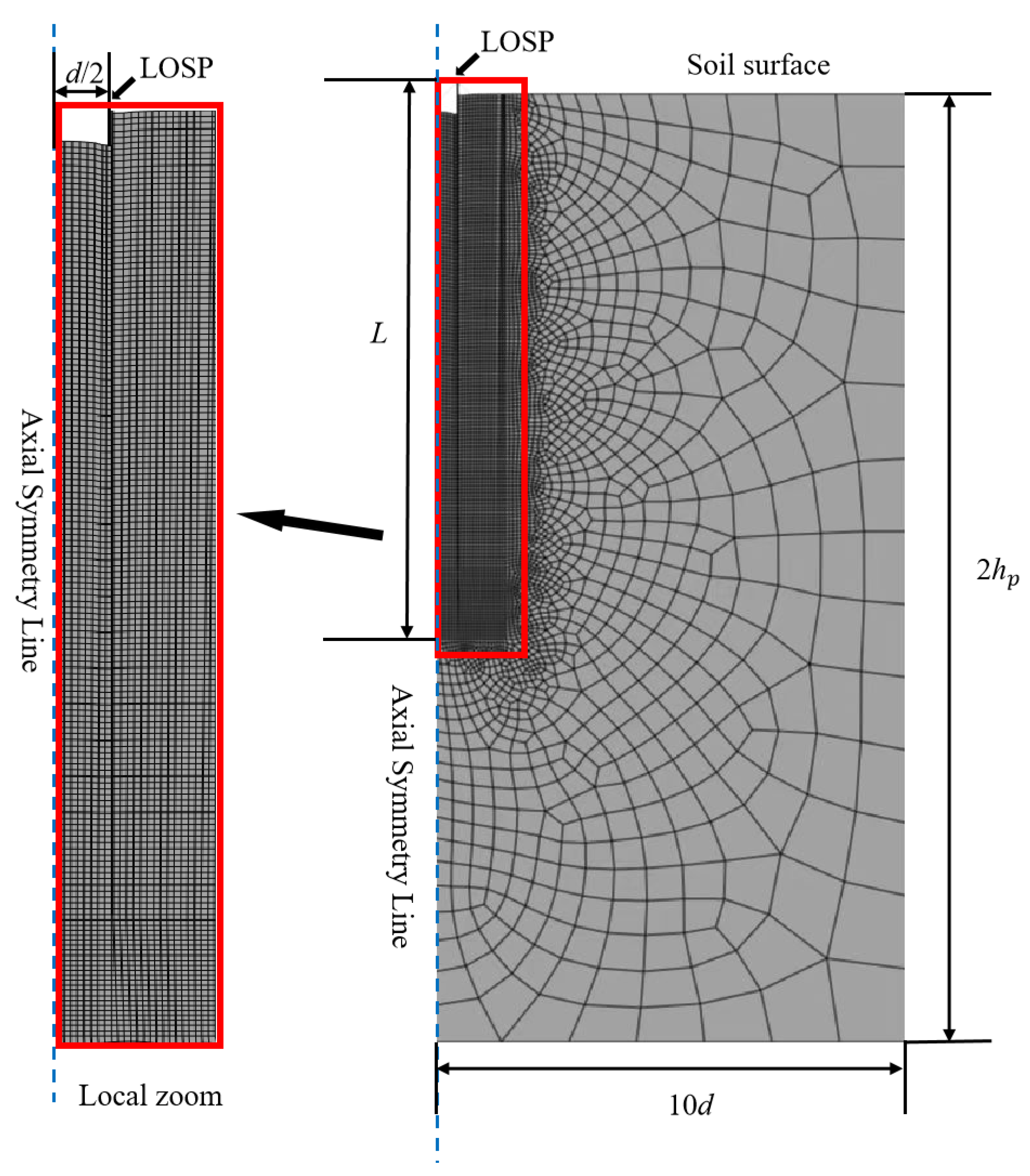
Figure 1. Schematic diagram of self-sinking force equilibrium of an open pile.
Jmse 10 00885 g001
Figure 2. Load transfer of LOSP under hammering load.
Jmse 10 00885 g002
Figure 3. Sensitivity analysis of the constant A.
Jmse 10 00885 g003
Figure 4. Sensitivity analysis of DCFR.
Jmse 10 00885 g004
Figure 5. Sensitivity analysis of the diameter of LOSP.
Jmse 10 00885 g005
Figure 6. A typical finite element model in this study.
Jmse 10 00885 g006
Figure 7. Comparison of displacement curves predicted from this study and the numerical result.
Jmse 10 00885 g007
Table 1. Parameters of open-ended piles installed by impact loading.
Elastic modulus of the pile, E (kPa)2 × 10⁸Inner diameter of the pile, d
(m)
2, 4, 6
Density of the pile
(kg/m3)
7.63 × 10³Pile length, L
(m)
10 d
Wave velocity, c (m/s)5119.7Ratio between thickness of pile wall and inner diameter, t/d0.015
Maximum number of summations of Fourier solutions, n1000DCFR0.1, 0.5, 1.0
Constant A in
Equation (19)
1, 1000, 1,000,000Shaft friction inside and outside the pile, fs
(kPa)
40.0
Single hammer penetration depth, Δl
(m)
0.01Average acceleration of soil inside and outside the pile, a (m/s2)1 (Outside the pile), 10 (Inside the pile)
Table 2. Adopted parameters values for comparison analysis.
ParametersValues
Internal diameter of pile, d (m)2.0
Wall thickness, tc (m)0.03
Pile length, L (m)20.5
Elastic modulus of pile, E (kPa)2 × 10⁸
Density of pile (kg/m3)7.63 × 103
Average frictional resistance inside and outside the pile, fs (kPa)35
Average acceleration of soil inside the pile (m/s2)17.0
Average acceleration of soil outside the pile (m/s2)12.1
Pile penetration by single blow, Δl (m)1.50
Pile penetration depth, hp (m)20.02
Shaft resistance dynamic coefficient, DCFR0.1
Duration of single blow (s)19.79
Constant A in Equation (18)65
Maximum number of summations of Fourier solutions, n1000
Publisher’s Note: MDPI stays neutral with regard to jurisdictional claims in published maps and institutional affiliations.

