Article

Prediction Method and Validation Study of Tensile Performance of Reinforced Armor Layer in Marine Flexible Pipe/Cables

1
Institute of Marine Machinery, College of Mechanical and Electrical Engineering, Harbin Engineering University, Harbin 150001, China
2
Department of Engineering Mechanics, Faculty of Vehicle Engineering and Mechanics, Dalian University of Technology, Dalian 116024, China
3
School of Civil Engineering, Dalian Jiaotong University, Dalian 116028, China
4
Department of Mechanical Engineering, Technical University of Denmark, 2800 Copenhagen, Denmark
5
Institute of Advanced Technology, Heilongjiang Academy of Science, Harbin 150001, China
*
Author to whom correspondence should be addressed.
J. Mar. Sci. Eng. 2022, 10(5), 642; https://doi.org/10.3390/jmse10050642
Submission received: 13 April 2022 / Revised: 2 May 2022 / Accepted: 4 May 2022 / Published: 8 May 2022
(This article belongs to the Special Issue Subsea Pipelines)

Abstract

:
Marine flexible pipe/cables, such as umbilicals, flexible pipes and cryogenic hoses, are widely adopted in ocean engineering. The reinforcing armor layer in these pipe/cables is the main component for bearing loads, which is a typical multi-layer helically wound slender structure with different winding angles for different devices. There has been no general theoretical methodology to describe the tensile performance of these flexible pipe/cables. This paper first introduces a theory to solve the tensile mechanical behavior of a helically wound structure. Based on the curved beam theory, a solution of the tensile stress of a helically wound slender is derived. Then, the deformation mechanism of the marine flexible pipe/cables structure with different winding angles is studied. Through comparing theoretical and numerical results, the deformation characteristic of the helically wound slender structure is further explained. It is found that a sectional torsional deformation generates when the structure with a larger winding angle is under tension condition, while the sectional deformation of the structure with a smaller winding angle is mainly tension. Finally, a couple types of marine flexible pipe/cables under the tension condition are provided to analyze the mechanical performance and compare the difference between different theoretical models. The research conclusion from this paper provides a useful reference for the structural analysis and design of marine flexible pipe/cables.

1. Introduction

Marine flexible pipe/cables are important devices in the ocean resource exploitation [1]. For example, umbilicals connect the floater and the manifold, which can be used to transmit the power and control signal, and flexible pipes can transport oil or gas. Cryogenic hoses link FLNG and LNG to deliver the liquefied natural gas. In order to improve the structural performance during operation, a single-layer or double-layer steel armor, the so-called “reinforced armor layer” is assembled inside the outer sheath, which is a usually helically wound structure. Helically wound structures can bear both axial and bending loads, which have been widely used in various industrial equipment [2]. For example, wire rope with a high tensile and fatigue strength is a key load-bearing component in special equipment, such as lifts and cranes [3]. Considering the complex loading condition in the sea environment, helically wound structures, such as umbilicals, flexible pipes and cryogenic hoses, have been introduced to ocean engineering [4]. Helically wound structures almost bear the overall axial load, and the accurate analysis of the structural tensile behavior is meaningful to the analysis and design of flexible pipe/cables [5].
In past research, the tensile behavior of helically wound structures has been a popular topic. Based on Hruska’s [6,7] assumption that the axial deformation of the helical wire is small and neglects the cross section shape, the helical wire can be taken as a whole component to derivate the tensile stiffness. Cardou [8] summarized multiple theoretical models of a single-strand and double-strand helical wire rope to evaluate the structural tensile property. In these models, the structural winding angles are usually small (0°~20°) so that the structure can bear the larger axial stretching. Knapp [9,10,11] proposed a theoretical model to calculate the axial strain and winding angle of the deformed structure, and in this model, the core deformation is not considered. The helically wound slender structure can be regarded as a spring model when the winding angle reaches 70°~90°, and the mechanical property of this type of structural model can be solved easily. In 2006, Feyrer [12] found that the local deformation of a single steel wire is affected by the fatigue and damage behavior of steel wire rope. For marine flexible pipe/cables, Kirchhoff’s nonlinear mechanical model was developed, and the theoretical accuracy was verified experimentally by Liu [13]. Some theoretical models are proposed to calculate the local pressure, radial force and contact force between the cable armor layer [14,15].
Many numerical methods have been gradually proposed to analyze the mechanical behavior of helically wound structures. In 2019, Chang and Chen [16] simulated the mechanical behavior of submarine cables under combined loads of tension, torsion and compression, and the coupling effects of loads generated a great influence on the analysis and design of submarine cables. In 2021, Yang [17] proposed a numerical method to calculate the nonlinear tension–torsion coupling effect. In the method, the stiffness of the structure inside the reinforced armor layer, or the so-called ‘core’ can be obtained easily. Then, the tension–torsion coupled stiffness can be calculated more accurately than the theoretical solution.
Recently, many scholars have proposed theoretical analysis models to analyze helically wound structures with different helix angles. However, there is a small number of discussions on the applicability of these models, especially when considering the helically wound structure in the cylindrical core. This paper discusses a tensile model of the helically wound structure wrapped around a cylindrical core. Based on the curved beam theory [12], a tensile solution to the helically wound structure with different winding angles is derived. Comparing with numerical results of three winding angle structures, the theoretical model is validated. Through comparing the error and application range of different theoretical analysis methods, the deformation mechanism is further explained.

2. Structural Characteristics of Reinforced Armor Layer in Marine Flexible Pipe/Cables

The different types of reinforced armor layers are required when marine flexible pipe/cables work in various conditions. The reinforced armor layer is typically a helically wound structure with different winding angles, as shown in Figure 1. For cables or umbilicals, the function of a reinforced armor layer is to resist the tensile load. Therefore, the winding angle of this type of structure is small, usually between 15° and 25° [18]. For flexible pipe, the reinforced armor layer is adopted for bearing the tension and inner pressure loads, and the winding angle is usually between 30° and 40° [19,20]. For cryogenic flexible hose, the reinforced armor layer mainly aims to bear the inner pressure and outer impacting loads, and the winding angle is usually between 75° and 80° [21]. The tensile strength of helically wound structures with a small angle is high, while the structure with an angle has a strong radial resistance capacity and is more flexible.
The mechanical model of helically wound structures can be generally established as shown n Figure 2. A helically wound structure with an undeformable cylindrical core is proposed. Considering the complexity of the reinforced armor layer, the following assumptions are given:
  • Ignoring the interaction between layers, only one of the armoring layers is taken to conduct the property analysis. The core is an undeformable cylinder.
  • The diameter of the helically wound structure is much smaller than that of the core.
  • Under the axial load, the section of the deformed structure remains flat.
  • The material property of the helically wound structure is isotropic.
  • The helically wound structure cannot be affected by the external bending moment per unit length.
Given that the armored layer is subjected to the axial tension F , and the average force on each helically wound wire is f . The winding angle is α , the thread pitch before the deformation is h = 2 π r   t a n   α and r is the distance between the central line of the core and the central line of the wounded wire. R 2 is the radius of the helically wound wire, R 1 is the radius of the cylindrical core and r = R 1 + R 2 .

3. Theoretical Model of Tensile Behavior of the Helically Wound Structure

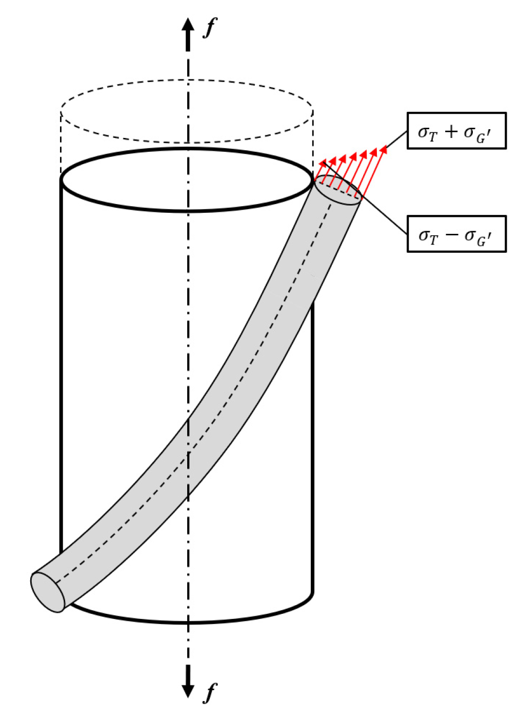
3.1. Mechanical Model of Helically Wound Structures

In order to explain the mechanical model clearly, a helically wound steel wire was taken, and the tensile loading condition is shown in Figure 3.
Assuming that the core is undeformable, the winding angle after stretching is α ¯ , the changed value of the winding angle because of stretching is Δ α = α ¯ α , the thread pitch after stretching is h ¯ and the amplitude of stretching deformation is Δ h = h ¯ h .
The axial strain ε can be expressed as:
ε = h ¯ h h
A micro-segment of the helically wound structure can be regarded as a 3D curve. Combining the curvature and torsion of the spatial helical curves, the subcomponents of the angular velocity vector are projected to the A, B, and C axes. κ , κ and τ indicate deformation curvature and torsion in per unit length. The curvature and torsion before deformation are expressed as:
κ = 0 ,   κ = sin 2 α r ,   τ = sin α cos α r
The curvature and torsion after deformation are expressed as:
κ ¯ = 0 ,   κ ¯ = sin 2 α ¯ r ,   τ ¯ = sin α ¯ cos α ¯ r
When the helically wound structure is only subjected to the tensile load, the force in each section along the winding path after canceling the boundary is the same. Three subcomponents of forces, two bending moments and one torque can be generated in the cross section.
N and N are the shear force components in the A- and B-axis directions on the cross-section of the helical structure, respectively. T is the axial tension of the central axis of the helically wound slender structure. G and G are the bending moments along the A and B axis, respectively. H represents the torsion moment on the central axis of the helically wound slender structure. X 1 , X 2 , and X 3 represent the linear load components per unit length of helically wound structures.
According to Hypothesis 4, its internal force can be expressed linearly through the curvature change and torsion per unit length as:
G = π R 2 4 4 E ( κ ¯ κ ) ,   G = π R 2 4 4 E ( κ ¯ κ ) ,   H = π R 2 4 4 E ( τ ¯ τ )
The thin rod theory of Love (1944) [22] gives the force and moment balance equations as Equation (5).
{ d N d S N τ + T κ + X 1 = 0 d N d S T κ + N τ + X 2 = 0 d T d S N κ + N κ + X 3 = 0 d G d S G τ + H κ N = 0 d G d S H κ + G τ + N = 0 d H d S G κ + G κ + Θ = 0
where Θ represents the external moment per unit length of the helically wound structure. According to Hypothesis 5, the balanced equation is simplified as:
{ N τ ¯ + T κ ¯ + X 1 = 0 X 2 = 0 X 3 = 0 G τ ¯ + H κ ¯ N = 0 N   = 0 Θ   = 0
The axial tension of the helically wound structure is T = π R 2 2 E ξ , where E is the elasticity modulus and ξ is the axial strain.
The length of the helically wound structure before stretching is L, and after stretching, the length becomes L(1 + ξ ). Therefore, Equation (1) can be rewritten as:
ε = h ¯ h h = ( 1 + ξ ) cos α ¯ cos α 1
Similarly, the rotation strain β of the helically wound structure can be expressed as:
β = ( 1 + ε ) tan α ¯ tan α
and cos α ¯ can be expressed as:
cos α ¯ = cos ( α Δ α ) = cos α + Δ α sin α
ξ is assumed to be small and higher-order terms are ignored, Equations (8) and (9) are rewritten as:
ε = ξ + Δ α tan α
β = ξ tan α Δ α = 0
Based on Equations (10) and (11), the axial strain ξ and the change value Δ α of the winding angle can be obtained by:
ξ = ε 1 + tan 2 α
Δ α = ε tan α 1 + tan 2 α
The curvature change and the torsion change per unit length can be linearized as:
R 2 Δ κ = 2 sin α cos α r / R 2 ε tan α 1 + tan 2 α
R 2 Δ τ = 1 2 cos 2 α r / R 2 ε tan α 1 + tan 2 α
where Δ κ and Δ τ are the curvature change and the torque change. The internal force of the helically wound structure can be calculated by:
{ G = E π R 2 4 ε cos 2 α tan 2 α 2 r ( 1 + tan 2 α ) H = E π R 2 4 ε tan α sin 2 α 2 r ( 1 + tan 2 α ) N = [ E π R 2 4 ε sin α cos α ( 1 2 cos 2 α ) + 2 E π R 2 4 ε cos 3 α sin α ] tan 2 α 4 r 2 ( 1 + tan 2 α ) T = E π R 2 2 ε 1 + tan 2 α
The stress caused by the axial tension T is:
σ T = T π R 2 2 = E ε 1 + tan 2 α
The maximum normal stress caused by the bending moment component G in the B-axis direction is:
σ G = 4 G π R 2 3 = 2 E R 2 ε cos 2 α tan 2 α r ( 1 + tan 2 α )
The maximum shear force caused by the torsion moment H on the central axis is:
σ H = 2 H π R 2 3 = E R 2 ε tan α sin 2 α r ( 1 + tan 2 α )

3.2. Theoretical Model of Tensile Mechanical Behavior of Helically Wound Structures with Typical Winding Angles

If the winding angle is between 0° and 20°, the helically wound structure can usually regard as a thin rod. One of typical appliccations of this type of helically wound slender structure is the tensile armor steel wire of dynamic submarine. The winding angle α is small, and sin α approaches zero. Therefore, some terms related to α can be dropped in the calculation. Equations (12) and (13) can be rewritten as the formula [9], which can be used to solve the axial strain ξ and the changed value of the winding angle Δ α by
ξ = ε   cos 2 α
cos α ¯ cos α = 1 + ε ξ
The internal force solution of the steel wire can be written as:
{ G = π 4 E R 2 3 ( 2 sin α cos α r / R 2 { cos 1 [ ( 1 + ε ε cos 2 α ) cos α ] α } ) H = π 4 E R 2 3 ( 1 2 cos 2 α r { cos 1 [ ( 1 + ε ε cos 2 α ) cos α ] α } ) N = H R 2 sin 2 α r / R 2 G R 2 sin α cos α r / R 2 T = π ε cos 2 α E R 2 2
The stress caused by the axial tension T , the maximum normal stress caused by the bending moment component G in the B-axis direction and the maximum shear force caused by the torque H can be calculated through the intermediate winding angle theory.
When the winding angle is between 70° and 90°, the helically wound slender structure will evolve into spring, and the mathematical model is shown in Figure 4. Here, α is a large value. Therefore, the terms related to cos α can be dropped, and the helically wound structures can be regarded as a classical spring model, the mechanical property of which can be solved briefly based on some existing methods. The tensile force f along the central axis of the core is expressed as [23]:
f = k Δ h
k = G R 2 4 4 N c r 3 = G R 2 4 4 r 3
where the shear modulus is G = E / 2 ( 1 + ν ) , E is the elasticity modulus, ν is the Poisson’s ratio, k is the spring constant and N c is the coil number. The tension force f can be obtained by:
f = ε E R 2 4 π 4 r 2 ( 1 + ν ) tan α
The torsion moment H of the spring is expressed as:
H = f r = ε E R 2 4 π 4 r ( 1 + ν ) tan α
The tension force f of the core is decomposed into the spring axial tension T as:
T = f cos α = ε E R 2 4 π cos α 4 r 2 ( 1 + ν ) tan α
The axial stress and the torsion stress can be expressed as:
σ T = T π R 2 2 = ε E R 2 2 cos α 4 r 2 ( 1 + ν ) tan α
σ H = 2 H π R 2 3 = ε E R 2 2 r ( 1 + ν ) tan α

4. Numerical Simulation Verification Analysis

Currently, Knapp’s [8] theory is used in the offshore engineering industry to solve the tensile properties of reinforced armored layers, while the spring theory is adopted for reinforced armor layers with large winding angles. Therefore, a general theoretical model of helically wound slender structures with different winding angles is derived in this paper. Thus, the accuracy of theoretical estimation in practical engineering can be improved. In order to validate the proposed theory models, an accurate 3D finite element model was built as a benchmark.

4.1. Establishing the Numerical Model

Using commercial software ABAQUS [24] to build a beam element of helically wound structures, helically slender structures were wound on a cylindrical shell model at different winding angles, from 10° to 90°, with a difference of 10°. The length of the model was a helical pitch, and the beam section was a circle with a radius of 2.5 mm. A model with a 45° winding angle was taken as an example to explain the proposed method. The material was elastoplastic, and the material parameters are shown in Table 1. [25]
When building a numerical model, a B31 beam element and a S4R shell element are taken to define the sectional property of the beam. There are interactions, such as the contact and extrusion, between the helically wound structure and the cylindrical core. In the numerical model, a universal contact between the beam element and the shell element is set up and the friction is not considered. Through a grid convergence analysis, high-efficient and accurate numerical models are given as the model meshed equally by 1000 grids along the axial direction, and the S4R shell model is divided by quadrilateral grids. After a numerical calculation, it was found that this numerical model could describe the contact between the beam and the shell very well. The finite element model is shown in Figure 5.

4.2. Loads and Boundary Conditions

Considering the axial periodicity of the helically wound structure, a proper way to apply loads on the ends is required for various loading conditions. An improper method may lead to an undesired displacement and a stress concentration. Therefore, we compared the mechanical property of different numerical models. The degrees of freedom of all points on the ending surface were respectively coupled with the ones of the central points as reference points RP-1 and RP-2. Shell elements were defined as rigid elements and were completely fixed with RP-2, and a displacement load with the amplitude of a thousandth the length of the pitch was applied to the RP-1. The loading and constraint conditions are shown in Figure 5. The quasi-static loading condition was applied to smooth the analysis step and avoid sudden stress generation. Because of the axial periodicity of the structure, the internal force and stress changed periodically. Therefore, the model with the length of a pitch was taken to conduct the numerical calculation.

4.3. Tensile Mechanical Behavior Deformation Mechanism

Figure 6 presents the numerical results of the mechanical property of helically wound structures with a winding angle of 45°, involving various loading conditions such as the axial tension, displacement, bending and torsion. Under the axial tension condition, the axial strain and torsional and bending deformation may appear. For this type of helically wound structures, the deformation is mainly the axial translation. The torsion direction at two ends is opposite and the bending strain is small during the middle segment, while the one is larger at ending parts and with an opposite direction. Due to the periodicity of helically wound structures, the mechanical behavior along the axial direction should be the same. Therefore, a further study on the tensile behavior was carried out in the following section.

5. Validation of Model Analysis

The winding angle of the helically wound slender structure is usually required to be changed for different service conditions. The angle in the steel wire rope or the umbilical is usually small, while the one in the vibration damping device is larger. Figure 7 presents the mechanical property of helically wound structures with different angles, where 10° and 20° are defined as smaller winding angles; 30°, 40°, 45°, 50°, and 60° are defined as intermediate winding angles; and 70° and 80° are defined as larger winding angles.

5.1. Mechanical Tensile Performance of Helically Wound Structures

Figure 7 shows the numerical solutions of the helically wound structure with different winding angles under stretching loads. From Figure 7a, the axial tensile force decreased linearly as the winding angle increased. The normal stress σ T was equal to the ratio of the axial force T to the cross-sectional area of the helically wound structure, so the stress change trend was similar to the tension change trend. From Figure 7b, the changing trend of the shear force along the B-axis direction was the same as that of the bending moment and the axial torque as the winding angle increased, and the internal force tended to the maximum when the winding angle was about 45°. Based on theoretical mechanics, the slender structure was tensile but easy to bend. With the increase of the winding angle, the load on the curved beam gradually changed from tension to shear, resulting in a linear decrease of the axial tension T, while the tensile strength of the structure was weakened. When the winding angle was about 45°, the structure was more comprehensive and the force was uniform, resulting in the internal force tending to the maximum value. From Figure 7b, not normally distributed, because the numerical solution outputted the data, the direction of the discrete nodal force was different, which caused the data to produce periodic fluctuations. Therefore, the limited output precision of the internal force of some angles caused the curve to fluctuate. As the winding angle changes, the theoretical results should also change regularly, which is also confirmed below.
Based on the simulation, the tensile force and stress of the helically wound structure increased linearly with the increasing winding angle. Another interesting behavior is that other internal forces and stresses may reach a peak when the winding angle reaches 45°. Therefore, a micro-element analysis method was applied to conduct a study on the symmetry of the mechanical behavior of the helically wound slender structure. When the winding angle increased, the torsion–stretch ratio changed, as shown in Figure 8. The cloud image was a torsion cloud image. The dotted line shows the undeformed state. As the winding angle increased, the torsional strain gradually increased and the stretching strain gradually decreased. When the winding angle was 45 degrees, the torsion–stretch ratio tended to the middle value. Both the torsional and tensile deformations were large, so the internal force and stress tended to the maximum when the winding angle was 45°.

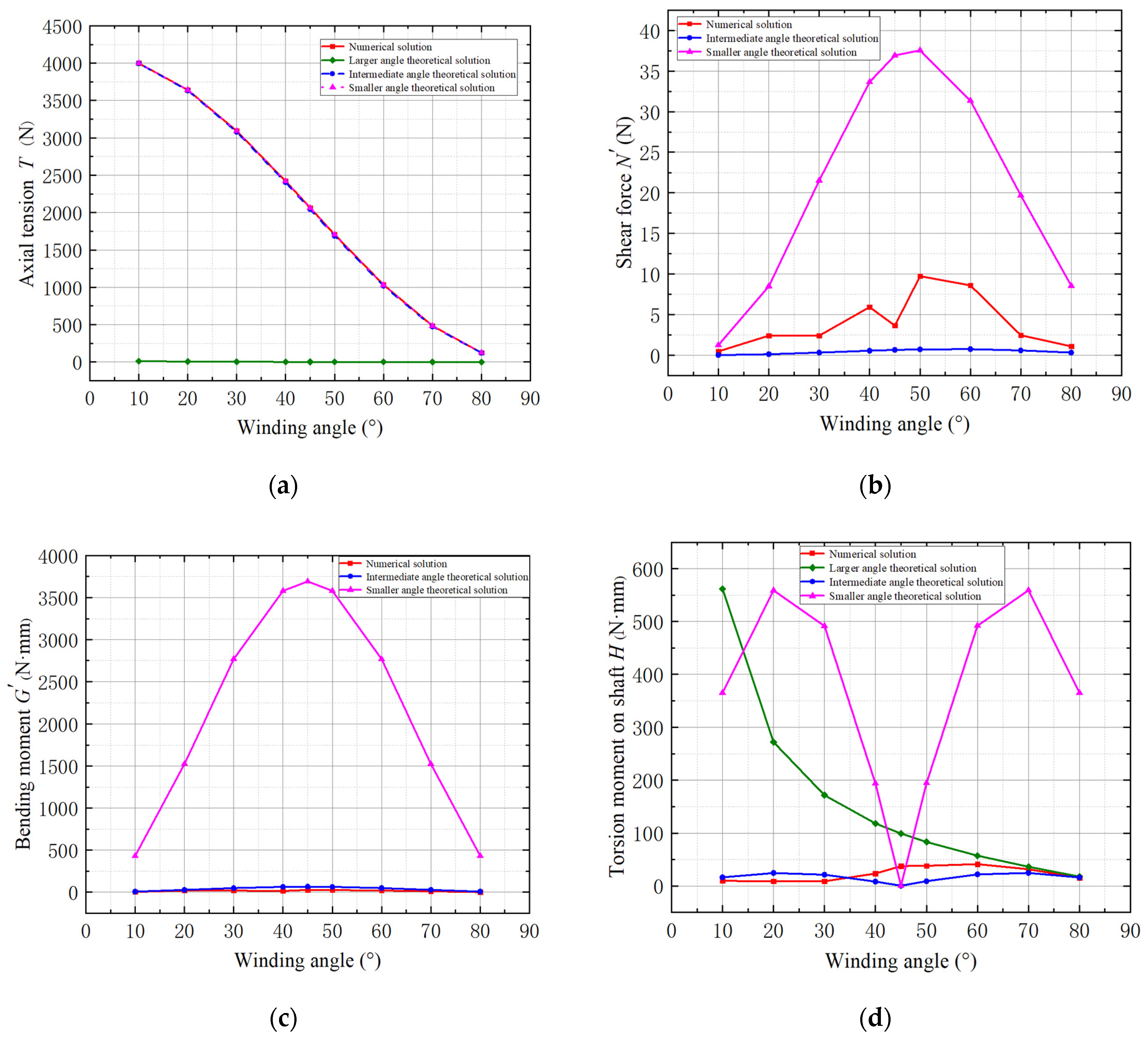
5.2. Theory Suitability Analysis

In order to discuss the application scope of different theories, the mechanical behavior was further analyzed based on different methods, and various solutions are plotted in Figure 9. It was observed that the intermediate winding angle theory and the small angle theory were basically consistent with the numerical solution in solving the axial tension T, and the solution error was less than 2%, which meets the requirements of engineering practice for the accuracy of the theoretical solution. For other internal forces, the changing trend of these two theoretical solutions are same as the numerical solution, but the accuracy of the intermediate winding angle solution is significantly better than that of the smaller winding angle theory. As the above theoretical models ignore the effect of torsion under the stretching condition, the accuracy of the solution for the smaller winding angle is better than that for the other winding angle. The smaller winding angle has a stronger tensile strength, which leads to a smaller axial strain. The classical spring theory assumes that the inner core can be contracted, and the tensile member is not subject to the reaction force of the inner core, resulting in a large error in the calculation of the axial stress T. The smaller winding angle theory ignores the influence of the changing value of the winding angle, resulting in only T with higher accuracy. The theoretical formulas of N , G and H have sine and cosine trigonometric functions, so the calculation results of the complementary winding angles are the same, resulting in a normal distribution of the curves. The stresses due to T, the maximum positive stress due to G and the maximum shear due to the torque H are obtained using the internal forces of the helically wound structure described above. Among them, the maximum normal stress due to N is small, which is not a priority strength requirement in engineering.
The theoretical formula for a middle winding angle has a higher accuracy and the widest applicability. In the theory for a large winding angle, the core is assumed to be deformable, which is more suitable for the spring than for the theory without considering the radial deformation.

5.3. Error Analysis of Tensile Behavior of Marine Flexible Pipe/Cables

The winding angles of helically wound structures in the engineering field are not all small or large, and structures with intermediate winding angles have been applied in some fields. The various types of helically wound armored or braided layers have been used in marine devices such as umbilicals, flexible pipes and cryogenic hoses, as shown in Figure 10. The winding angles of 20°, 30° and 80° are used for different functions.
The marine flexible pipe/cables mainly bear the axial tensile load during operation. The axial tensile bearing capacity is mainly affected by the tensile stiffness and strength. Tensile stiffness E A = σ A / ε . σ is the axial normal, ε is the axial strain, and A is the section area. In the numerical calculation, the axial strain ε and section area A were the same, so the tensile stiffness was only related to axial normal stress σ . The tensile strength was the minimum breaking force, which can be calculated by F = ε m a x E A / c o s α = σ ε m a x A / ε c o s α . Here, ε m a x is the yield strain of the material, and α is the winding angle of the helically wound slender structure. Therefore, the tensile strength was mainly affected by the normal stress σ .
In the design stage, the theoretical model of a small winding angle is unable to satisfy the design requirements because of the ignorance of the torsion deformation, which not only increases the manufacturing cost but also easily causes safety accidents. Therefore, this paper analyzed the error of stress estimation of marine flexible pipe/cables. The tensile, bending and torsional deformation may appear when stretching helically wound slender structure. The normal stress σ = σ T + σ G , as shown in Figure 11, and σ T were the normal stress due to tensile deformation, and σ G was the normal stress due to bending deformation.
Figure 12 presents an error comparison result. From Figure 12a, the error of the intermediate winding angle theory was smaller than that of the smaller angle theory. Because these theories ignore torsion, while the winding angle increased, the error increased, and this phenomenon is more obvious for the smaller winding angle theory. Because the Poisson effect was considered in the simulation, the theoretical normal stress of the intermediate winding angle was slightly larger than that of the numerical solution, and the error was less than 2%. From Figure 12b, when the winding angle was 45°, the shear stress error of the intermediate winding angle was the largest, reaching up to 100%. However, it was much smaller than the normal stress and had little effect on the resultant force. In order to improve the theoretical estimation accuracy of marine flexible pipe/cables, the more general method calculation error of three representative pipe/cables is proposed:
  • The normal stress of the umbilical increases by 0.36%, and the shear stress decreases by 50.51%.
  • The normal stress of the flexible pipe increases by 0.62%, and the shear stress decreases by 67.62%.
  • The normal stress of the cryogenic hose increases by 0.72%, and the shear stress decreases by 8.44%.
In summary, although the error is within the allowable range, when the tensile stress of helically wound structures is large, the effect cannot be underestimated. Therefore, the influence of the above errors should be considered in the calculation of engineering to improve the calculation accuracy.

6. Conclusions

In this paper, combining theoretical and numerical methods, the mechanical mechanism of the helical winding structure under tension was deeply studied. The conclusions are as follows:
  • A more general method was deduced for different winding angles, which solves the problem of poor applicability of previous theoretical formulas. The theoretical calculation errors of different marine flexible pipe/cables were analyzed, and the theoretical calculation accuracy was improved.
  • Under the premise of the same axial strain, the tensile–torsion ratio of different winding angles was analyzed. It was found that with the increase of winding angle, the torsion of the structure gradually replaced the stretch, leading to increased error, so the effect of torsion should be fully considered.
  • When the increase of winding angle T decreased linearly, the tensile strength decreased, and the theoretical formulas of N , G and H had sine and cosine trigonometric functions. Therefore, the calculation results of the complementary winding angles were the same, resulting in a normal distribution of the curves.
In summary, the intermediate winding angle theoretical provides positive suggestions for the design and verification of helically wound structures. Future work will consider the mechanical mechanism of helically wound structures under bending and torsion.

Author Contributions

Conceptualization, H.W., Z.Y., J.Y., G.W., D.S., B.Z. and Y.L.; Data curation, H.W.; Formal analysis, H.W. and J.Y.; Funding acquisition, Y.L.; Investigation, H.W. and Z.Y.; Methodology, Z.Y.; Project administration, Y.L.; Resources, Y.L.; Supervision, Z.Y. and J.Y.; Visualization, H.W. and G.W.; Writing—original draft, H.W. and Z.Y.; Writing—review & editing, H.W. and Z.Y. All authors have read and agreed to the published version of the manuscript.

Funding

This research was funded by the National Natural Science Foundation of China, grant number 52001088, the Natural Science Foundation (Key Joint Fund of Shandong Province), grant number U1906233, the Major Science and Technology Innovation Project in Shandong Province, grant number 2019JZZY010801, Natural Science Foundation of Heilongjiang Province, grant number LH2021E050, the State Key Laboratory of Structural Analysis for Industrial Equipment, grant number GZ20105.

Institutional Review Board Statement

Not applicable.

Informed Consent Statement

Not applicable.

Acknowledgments

The authors highly appreciate the financial support provided by the Natural Science Foundation. We would like to thank research center of marine equipment in Dalian University of Technology for all of their support for permitting us to use their facilities and/or resources to make this project possible.

Conflicts of Interest

The authors declare no conflict of interest.

References

  1. Xia, R.; Zhang, X.; Zheng, L.J. Reliability analysis of an umbilical under ultimate tensile load based on response surface approach. Underw. Technol. 2020, 37, 87–93. [Google Scholar]
  2. Meng, X.B.; Gao, K.; Sun, Y.H. Mathematical modeling and geometric analysis for wire rope strands. Appl. Math. Model. 2015, 39, 1019–1032. [Google Scholar]
  3. Xiang, L.; Wang, H.Y.; Chen, Y. Modeling of multi-strand wire ropes subjected to axial tension and torsion loads. Int. J. Solids Struct. 2015, 58, 233–246. [Google Scholar] [CrossRef]
  4. Inagaki, K.; Ekg, J.; Zahrai, S. Mechanical analysis of second order helical structure in electrical cable. Int. J. Solids Struct. 2007, 44, 1657–1679. [Google Scholar] [CrossRef] [Green Version]
  5. Usabiaga, H.; Pagalday, J.M. Analytical procedure for modelling recursively and wire by wire stranded ropes subjected to traction and torsion loads. Int. J. Solids Struct. 2008, 45, 5503–5520. [Google Scholar] [CrossRef] [Green Version]
  6. Hruska, F.H. Radial forces in wire ropes. Wire Wire Prod. 1952, 27, 459–463. [Google Scholar]
  7. Hruska, F.H. Tangential forces in wire ropes. Wire Wire Prod. 1953, 28, 455–460. [Google Scholar]
  8. Cardou, A.; Jolicoeur, C. Mechanical models of helical strands. Appl. Mech. Rev. 1997, 50, 1–14. [Google Scholar] [CrossRef]
  9. Knapp, R.H. Derivation of a new stiffness matrix for helically armoured cables considering tension and torsion. IJNME 1979, 14, 515–529. [Google Scholar] [CrossRef]
  10. Knapp, R.H. Structural modeling of undersea cables. J. Offshore Mech. Arct. Eng. 1989, 111, 323–330. [Google Scholar] [CrossRef]
  11. Knapp, R.H. Design methodology for undersea umbilical cables. In Proceedings of the OCEANS 91 Proceedings, Honololu, HI, USA, 1–3 October 1991; pp. 1319–1327. [Google Scholar]
  12. Feyrer, K. Wire Ropes: Tension, Endurance, Reliability; Springer: Berlin/Heidelberg, Germany, 2007; pp. 1–322. [Google Scholar]
  13. Liu, Y.W.; Chen, J.B.; Liu, J.G. Nonlinear mechanics of flexible cables in space robotic arms. Orig. Pap. 2018, 94, 649–667. [Google Scholar]
  14. Lanteigne, J. Theoretical estimation of the response of helically armored cables to tension, torsion, and bending. J. Appl. Mech. 1985, 52, 423–432. [Google Scholar] [CrossRef]
  15. Li, X.; Liang, L.; Wu, S. Analysis of mechanical behaviors of internal helically wound strand wires of stranded wire helical spring. Proc. Inst. Mech. Eng. C J. Mech. Eng. Sci. 2018, 232, 1009–1019. [Google Scholar] [CrossRef]
  16. Chang, H.C.; Chen, B.F. Mechanical behavior of submarine cable under coupled tension, torsion and compressive loads. J. Appl. Mech. 2019, 189, 106272. [Google Scholar] [CrossRef]
  17. Yang, Z.X.; Su, Q.; Yan, J. Study on the nonlinear mechanical behaviour of an umbilical under combined loads of tension and torsion. Ocean Eng. 2021, 238, 109742. [Google Scholar] [CrossRef]
  18. Tang, M.G.; Yan, J.; Wang, Y. Tensile stiffness analysis on ocean dynamic power umbilical. China Ocean Eng. 2014, 28, 259–270. [Google Scholar] [CrossRef]
  19. Zhu, X.H.; Lei, Q.L.; Meng, Y. Tensile response of a flexible pipe with an incomplete tensile armor layer. J. Offshore Mech. Arct. Eng. 2021, 143, 1–9. [Google Scholar] [CrossRef]
  20. Yue, Q.J.; Lu, Q.Z.; Yan, J. Tension behavior prediction of flexible pipelines in shallow water. Ocean Eng. 2013, 58, 201–207. [Google Scholar] [CrossRef]
  21. Yang, Z.X.; Yan, J.; Chen, J.L. Multi-objective shape optimization design for liquefied natural gas cryogenic helical corrugated steel pipe. J. Offshore Mech. Arct. Eng. 2017, 139, 1–11. [Google Scholar] [CrossRef]
  22. Love, A.E.H. A Treatise on the Mathematical Theory of Elasticity; Cambridge University Press: Cambridge, UK, 1944; p. 305. [Google Scholar]
  23. Lemaitre, J.; Chaboche, J.L.; Maji, A.K. Mechanics of solid materials. J. Eng. Mech. 1992, 119, 642–643. [Google Scholar] [CrossRef]
  24. ABAQUS CAE. Analysis User’s Manual Version 6.12; Dassault Systemes Simulia, Inc.: Johnston, RI, USA, 2012. [Google Scholar]
  25. Yin, Y.C.; Lu, Q.Z.; Wu, S.H. Experimental study on the interlayer friction and wear mechanism between armor wires of umbilicals. Mar. Struct. 2021, 80, 103102. [Google Scholar] [CrossRef]
Figure 1. Structural characteristics of the marine flexible pipe/cables armoring layer.
Jmse 10 00642 g001
Figure 2. Schematic diagram of the helically wound structure subjected to tensile load.
Jmse 10 00642 g002
Figure 3. Schematic diagram of the deformation of the helically wound structure.
Jmse 10 00642 g003
Figure 4. Schematic diagram of spring parameters.
Jmse 10 00642 g004
Figure 5. Finite element model and boundary conditions.
Jmse 10 00642 g005
Figure 6. Finite element cloud map. (a) Axial tension, (b) stretch, (c) bending, (d) torsion.
Jmse 10 00642 g006
Figure 7. Numerical solutions of internal forces at different winding angles. (a) Axial tension, (b) other internal forces.
Jmse 10 00642 g007
Figure 8. The torsion–stretch ratio diagram with different winding angles.
Jmse 10 00642 g008
Figure 9. Internal force comparison point line diagram. (a) Axial tension, (b) shear force in the B-axis direction, (c) B-axis direction bending moment, (d) torsion moment on the shaft.
Jmse 10 00642 g009
Figure 10. Three pipe/cables winding angles.
Jmse 10 00642 g010
Figure 11. Stress diagram.
Jmse 10 00642 g011
Figure 12. Error comparison. (a) Normal stress error, (b) shear stress error.
Jmse 10 00642 g012
Table 1. Model material parameters.
Elasticity Modulus (MPa)Poisson’s RatioDensity (kg·m−3)
210,0000.37800
Publisher’s Note: MDPI stays neutral with regard to jurisdictional claims in published maps and institutional affiliations.

