Article

CFRP Strengthening and Rehabilitation of Inner Corroded Steel Pipelines under External Pressure

1
State Key Laboratory of Hydraulic Engineering Simulation and Safety, Tianjin University, Tianjin 300072, China
2
College of Mechanical and Marine Engineering, Beibu Gulf University, Qinzhou 535000, China
3
Tianjin Key Laboratory of Port and Ocean Engineering, Tianjin University, Tianjin 300072, China
4
School of Architecture and Civil Engineering, Xiamen University, Xiamen 361005, China
*
Author to whom correspondence should be addressed.
J. Mar. Sci. Eng. 2022, 10(5), 589; https://doi.org/10.3390/jmse10050589
Submission received: 10 April 2022 / Revised: 22 April 2022 / Accepted: 25 April 2022 / Published: 26 April 2022
(This article belongs to the Special Issue Subsea Pipelines)

Abstract

:
The objective of this study was to investigate the performance of pipelines repaired with carbon-fibre-reinforced polymer (CFRP) under external pressure. The repaired pipeline experienced defects in terms of thinning of its local inner wall. The three-dimensional finite element method was used to analyse the collapse pressure of repaired pipes with internal corrosion defects. The traction–separation law and interlaminar damage criterion were applied to simulate the collapse process of repaired pipes. The results show that the collapse pressure of the composite-repaired pipe increased and the CFRP significantly reduced the strain in the defect region. It was observed that the ovality of the corrosion defect region was reduced and that the repair effectiveness mainly depended on the length, thickness, and interlayer cohesion.

1. Introduction

In recent years, with the reduction in resources inland and increasing difficulties in mining, submarine energy has been developing. Deep-sea energy mainly includes oil, gas, and minerals, which are transported through pipelines. Pipelines are widely used to transport deep-sea resources because of their safety and efficiency. However, the submarine environment is complex, so pipelines can be worn thin and corroded with the transportation of ore, which could eventually lead to the collapse of the pipeline in the deep-sea high-pressure environment, causing serious leakage problems.
Researchers have analysed the collapse of submarine pipelines in deep-sea high-pressure environments [1,2,3]. The local buckling of the pipeline occurs under high external pressure, and this buckling would propagate along the pipeline at a high speed, resulting in catastrophic accidents [4]. Dyau and Kyriakides and Sakakibara et al. [5,6] studied the pipe buckling caused by local collapse and proposed an empirical analysis method to evaluate the residual collapse pressure of an internally corroded pipeline. Netto [7] proposed an empirical formula of pipe collapse pressure through experiments and numerical simulation data. Meanwhile, researchers have investigated the influence of different defects. Ramasamy and Tuan Ya [8] studied the effect of dent defects on the collapse pressure. Wang et al. [9,10,11] studied the influence of pipelines’ external surface corrosion on their external-pressure-bearing capacity. Through tests and program development and calculation, it was found that random pitting corrosion increases the risk of a pipeline’s collapse and changes its buckling shape. Moreira Junior et al. [12] studied the effects of internal local corrosion and wall thickness eccentricity on pipeline collapse pressure. Zhang and Pan [13] analysed the effects of thickness eccentricity and overall ovality on pipeline crushing pressure. In [14,15], a local corrosion model is developed, and it is found that the defects caused by internal wear and corrosion have a great impact on the ability of a pipeline to withstand external water pressure and axial load.
In view of the above-mentioned situations that lead to local instability of pipelines, several researchers have put forward disaster-reduction measures for the arrestor, including steel and composite materials [16]. In the early stage, Johns et al. [17] and Hahn et al. [18] carried out experimental research on the influence of pipe arrestors on buckling propagation, and their research proved that the arrestor can enhance the pipe’s local collapse pressure. Kyriakides’s team has performed many experiments and analyses on the performance of steel buckling arrestors, finding that steel ring buckling arrestors can effectively prevent pipe buckling propagation and large area damage along pipelines. They also found that the effect of integral buckling arrestors is significantly better than that of slip-on arrestors. The interaction between buckling arrestors and pipes was also found to have a significant influence on propagation pressure [19,20,21,22,23]. However, the arrestors can only prevent the propagation of buckling and do not stop the collapse process. Once the pipeline collapses, it needs to be replaced to restore it to its working capacity but doing so is expensive. If effective measures can be taken in time to repair the pipeline, large area damage and high maintenance costs can be prevented. The study of deep-water pipeline repair is of great significance. Common repair methods of deep-water pipes include welding, grouting, sleeves, and composite materials [24,25,26,27,28].
At present, methods of repairing defective pipelines mainly involve cutting the damaged pipe section and replacing it, which is expensive and unsafe. Several experiments have found that the effect of the CFRP is better than that of GFRP when repairing pipes of the same size, but the tensile strength of GFRP is lower than that of the CFRP [29,30]. Several studies have been carried out to provide a reliable experimental and theoretical basis for CFRP pipeline repairs. It has been found that the CFRP has advantages in terms of high specific strength and stiffness and performance weight ratio [31,32]. Meanwhile, the bonding of CFRP and pipelines could improve pipelines’ pressure capacity [33], increase their ability to resist the lateral impact [34,35], strengthen the pipeline weld [25], and enhance the stability of its tubular structure [36] and the bearing capacity of the pipeline axial force and bending moment. Using their developed numerical model, Mokhtari and Alavi Nia [37] found that the repaired pipeline can reduce the influence of the staggered soil layer on the pipeline. Shamsuddoha et al. [38] proposed a CFRP manufacturing method and found that the bearing capacity of the repaired pipeline was improved. Meriem-Benziane et al. [39] studied the repair of the longitudinal crack of an API X65 pipeline under internal pressure with CFRP and found that CFRP could effectively enhance its bearing capacity under internal pressure, and they proposed a suitable safety evaluation method for CFRP crack repair. The bonding mechanical properties between CFRP and steel have also been widely investigated, with an overspread use in many fields [40] thanks to the good mechanical properties obtained in combination with steel plates. It was found that the surface roughness of the steel plate and repair environment have an impact on the bonding properties of CFRP [41]. The steel plate repaired by CFRP has strong durability in seawater [42]; the CFRP could repair the defected steel plate and still maintain a good repair effect in the marine environment [43], and the ultimate strength of cracked structures can be restored by CFRP [43]. In conclusion, CFRP is suitable for repairing deep-water pipelines.
Nevertheless, the research on improving the structural strength using CFRP has not been fully optimized. Based on the test data [44], suitable numerical models for simulating pipelines repaired by CFRP have been proposed in the literature. In this study, the finite element method is used to determine the collapse pressure and collapse mode of internally corroded pipelines repaired using CFRP. In addition, the mechanism of CFRP repairing internally corroded pipelines under external water pressure is studied. The collapse pressure, stress, ovality, and plastic deformation of the repaired pipeline are calculated with a numerical method. Finally, the effects of thickness and length of the CFRP, interlayer bonding, and internal corrosion metal loss rate on the collapse pressure are systematically analysed.

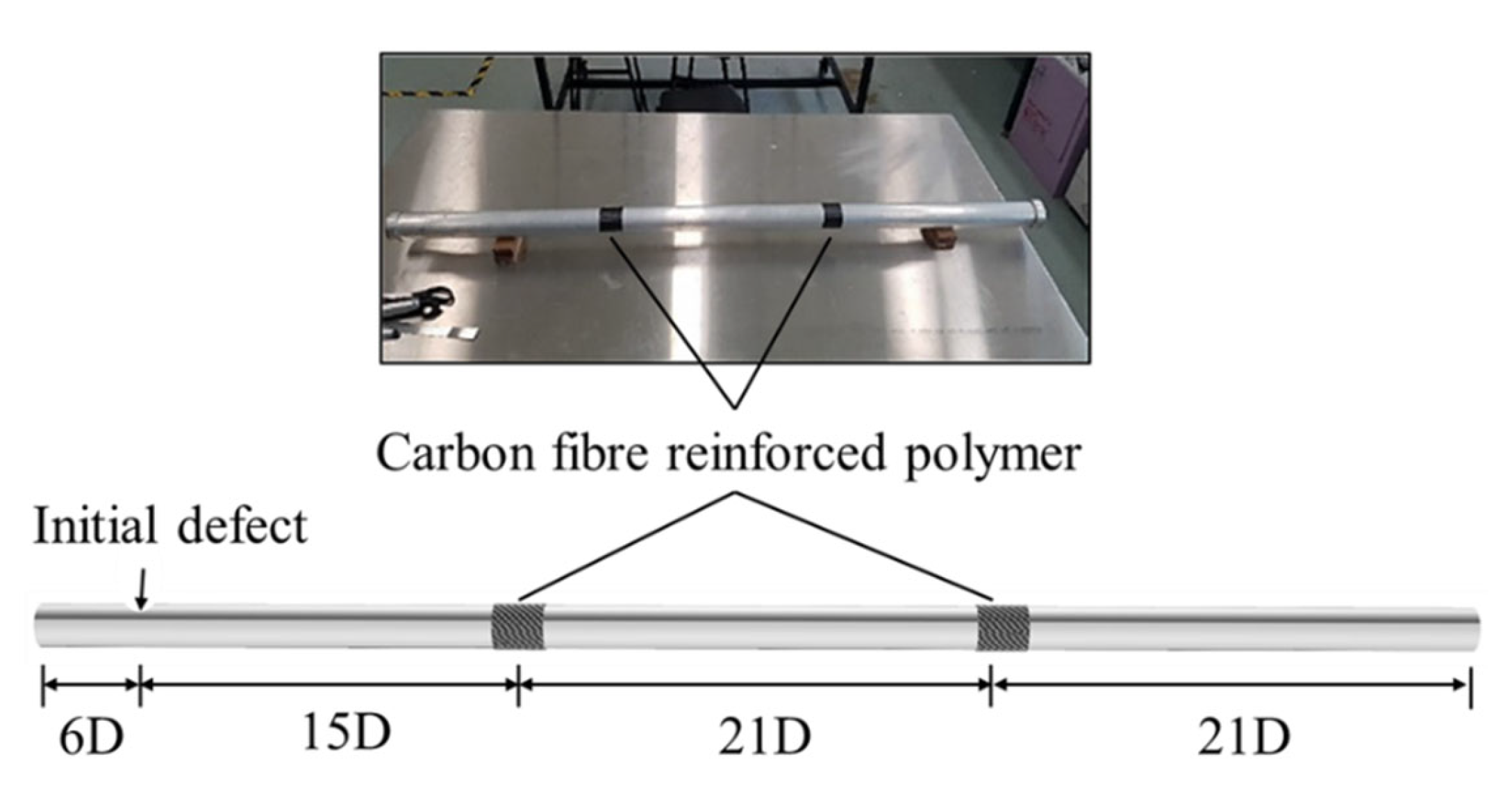
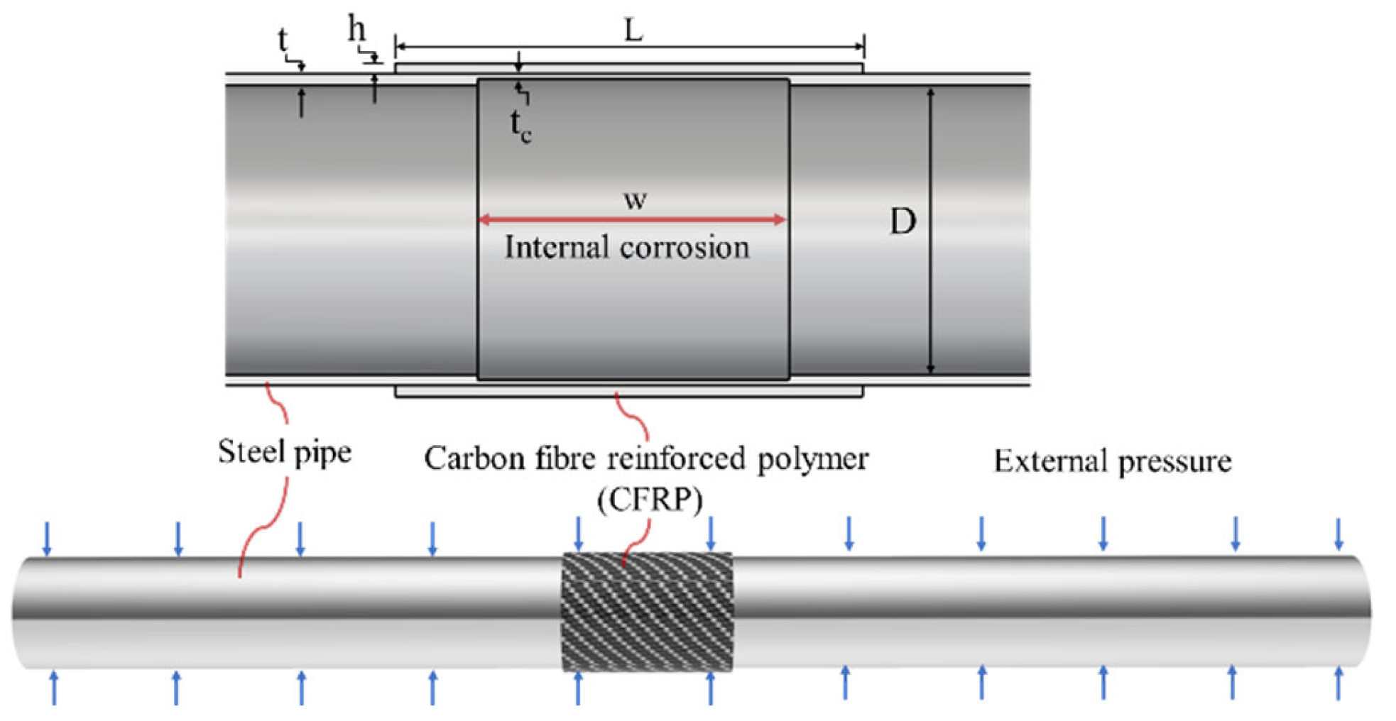
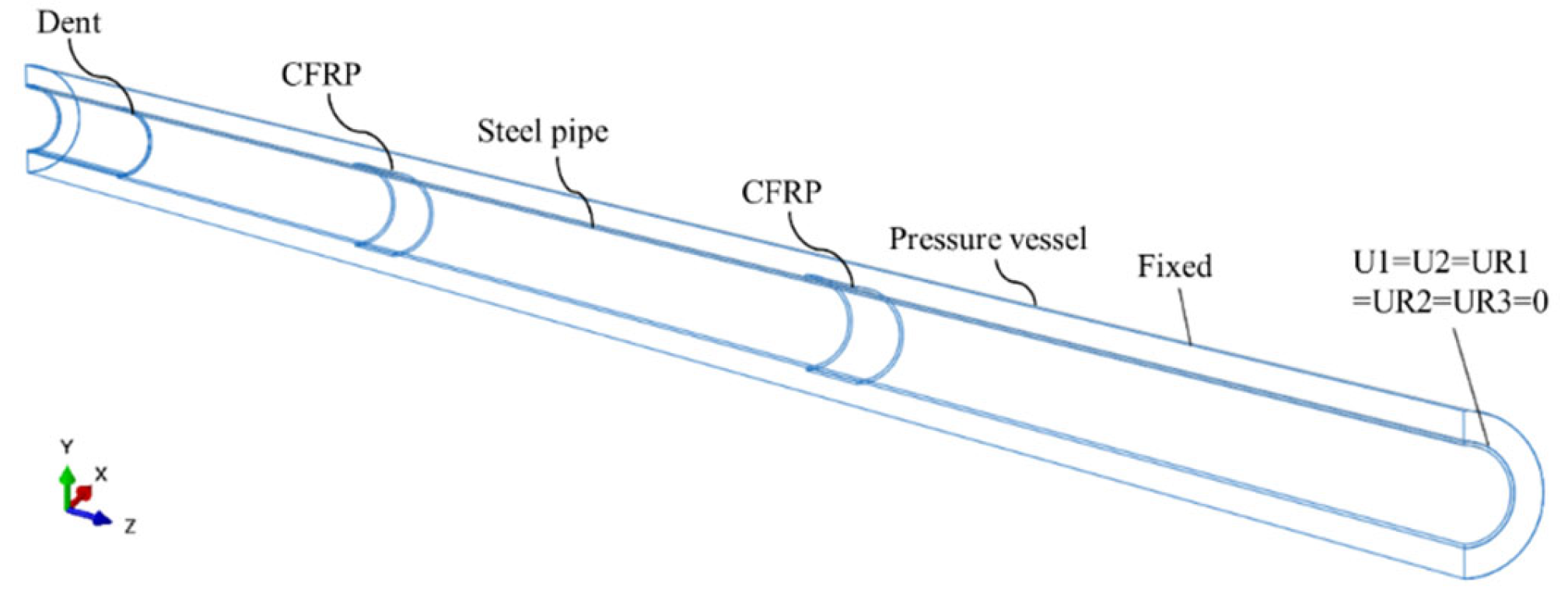
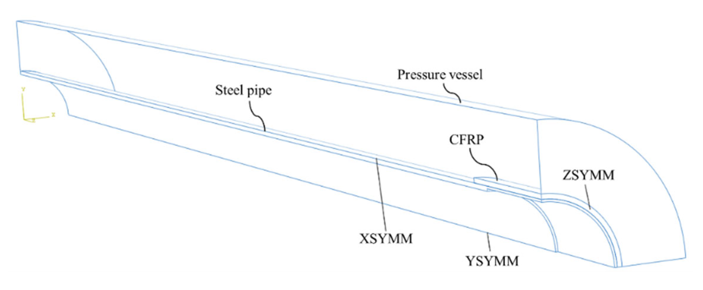
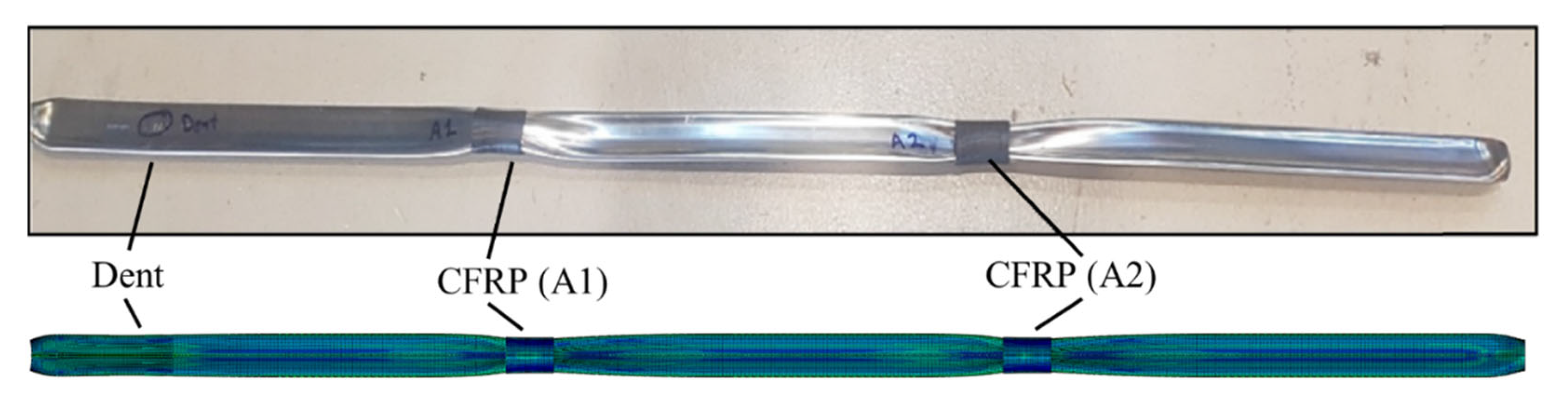
2. Description of the Repaired Model

A three-dimensional elastic–plastic finite element model is used to simulate the collapse and buckling propagation of pipelines under external pressure. This study is divided into two parts. In the first part, a model suitable for analysing the CFRP buckling arrestor is developed, and the feasibility and accuracy of the model are verified in relation to the literature [44]. The second part investigates the effectiveness of CFRP on the buckling behaviour of an annular internally corroded steel pipe.

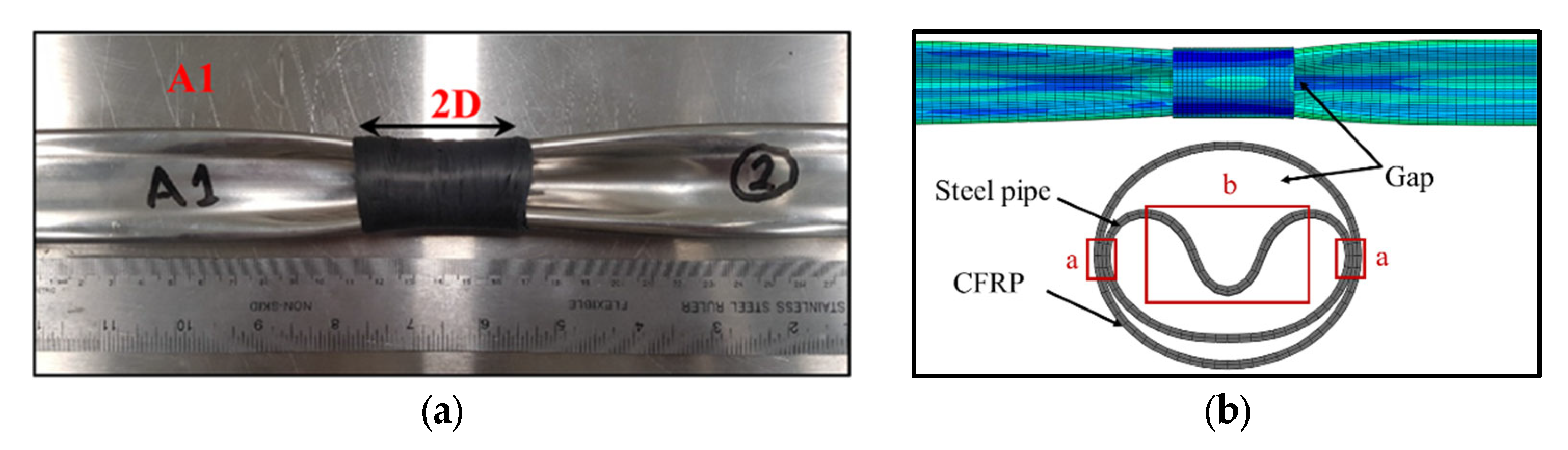
2.1. Numerical Model
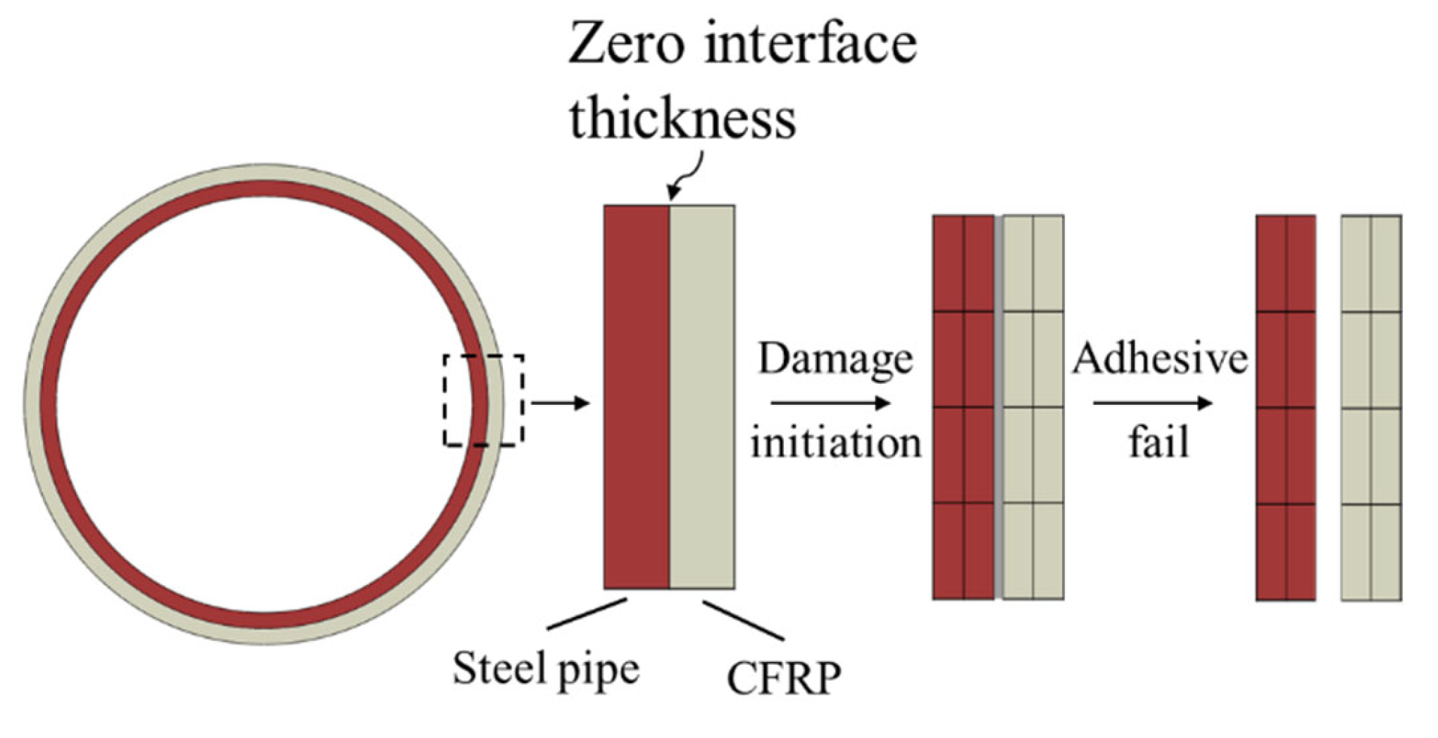
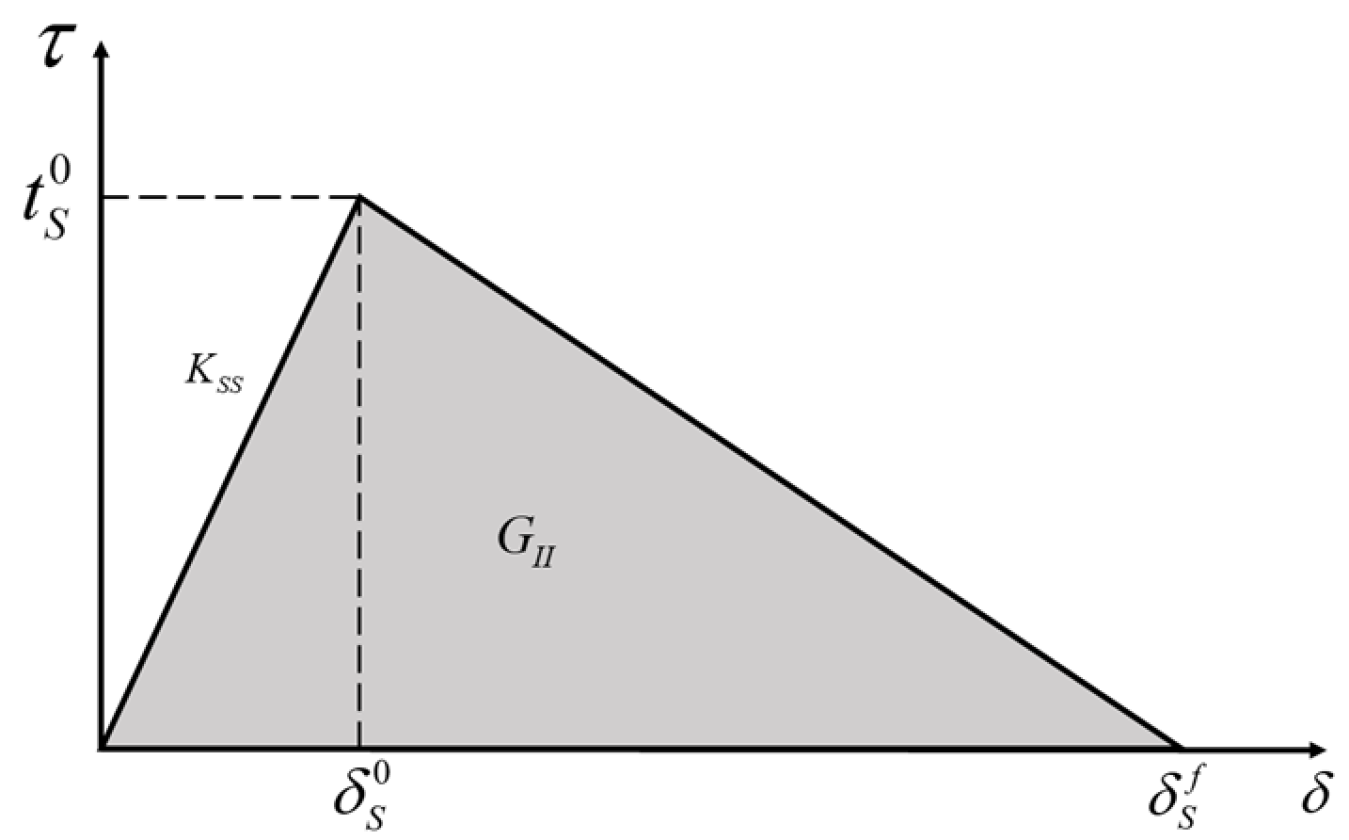
The aim of this paper is to study the repair effect of CFRP on an inner corroded pipeline under external pressure, and the methodology followed is a simulation experiment. ABAQUS/Standard code [45] was applied for investigation; steel pipe and CFRP were modelled using brick elements C3D8R (8-node linear brick).
For the loading, based on the requirements of the experiment, the continuous water injection in the pressure vessel was simulated using numerical simulation technology. As the internal water pressure increases, the pipeline collapses, and the water pressure in the pressure vessel drops. Loading continued until the water pressure was steady. The keyword “FLUID FLUX” was used to simulate the process of continuous and uniform water injection and pressurization in the pressure vessel.
For boundary conditions, the pressure vessel was fixed, and the sides of the steel pipe were set to be symmetrical along the X-axis (XSYMM: U1 = UR2 = UR3 = 0) and along the Y-axis (YSYMM: U2 = UR1 = UR3 = 0). The end of the steel pipe was set to be hinged, allowing axial movement along the pipe. The displacement in the remaining directions was 0. The pipe section at the defect and the section of the CFRP were set to be symmetrical along the Z-axis (ZSYMM = U3 = UR1 = UR2 = 0).
The steel is elastic–plastic material. When the element stress is less than the yield stress, the pipeline is in the elastic stage, and the stress–strain slope is Young’s modulus E. When the element stress is greater than the yield strength, the steel is in the plastic stage. The element will incur plastic deformation. The pressure vessel adopts rigid body.
First, to verify the accuracy of the model, we used the same material property parameters as the test group 28D 2. As shown in Figure 1, the CFRP was located at 1/3 and 2/3 of the stainless-steel pipes, with the pipe diameter D = 25.4 mm and the wall thickness t = 0.9 mm, respectively. An initial defect in the shape of the dent was generated at the position 6D away from the end so that the collapse position of the pipe would start from the end. To apply dents, the pipe was clamped in the jaws of a universal testing machine and a rigid semi-circular rod of the same diameter was gradually pressed to produce an ovality ratio of less than 1% Δ0. The defects were quantified by measuring the maximum and minimum diameters (Dmax and Dmin) of the dented pipe and measured by the ovality that Δ0 indicates: Δ0 = (DmaxDmin)/(Dmax + Dmin).
A dent with an ovalityΔ0 less than 1% was also introduced into the numerical model, as shown in Figure 1. The effect of CFRP on the propagation pressure is the goal of this study. The initial defect was only to ensure that the collapse position started from one end, so the residual stress effect of the dent defect in the test can be ignored. When the accuracy of the model was verified, the symmetrical model was used to save the calculation cost, as shown in Figure 2.
Then, a model was established to investigate the mechanism of CFRP in repairing corroded pipelines. Pipelines are corroded internally, and local pipe walls are thinned. As shown in Figure 2, the CFRP wrapped around the local defect. The outside of the pipe was evenly subjected to external pressure. The repair effect and mechanism of the CFRP arrestor on internally corroded pipes were studied by numerical simulation. Figure 2 illustrates the geometric features, where the pipe length is 1 m, D is the pipe diameter (D = 25.4 mm), t is the thickness of the pipe wall (t = 0.9 mm), L is the longitudinal length of the CFRP, tc is the wall thickness at the pipe defect, w is the longitudinal length of the defect, and h is the thickness of the CFRP. Pipelines were not subjected to internal pressure.

2.2. Adhesive Model

In this study, the CFRP was first subjected to external water pressure and then separated from the pipe when buckling propagation occurred, as shown in Figure 3a. As can be seen from Figure 3b, when the pipe buckling propagates across the CFRP, the pipe cross-section is U-shaped. There is a large gap between the pipe and the CFRP; thus, it can be inferred that the failure mode of the interlaminar bonding is the steel–adhesive interface failure.
The interaction of pipelines with CFRP was simulated using the bond layer model in ABAQUS®. The material parameters described in the literature were adopted for the interlaminar bonding of the pipe [45]. Since the CFRP is subjected to external water pressure in this study, if the finite thickness method in the literature is used to simulate the adhesive layer, the calculation will not converge during the hydraulic loading process. Therefore, the simulation method of the no-thickness adhesive layer was adopted in this study. As shown in Figure 4, the advantage of this method is that when the CFRP layer is subjected to external water pressure, a hard contact can be set between the CFRP and the steel pipe, and the pressure exerted on the CFRP can be transmitted to the outer surface of the pipe, making it more realistic to restore the process of experiments.
The behaviour of the adhesive layer is governed by the traction–separation law, and the following parameters were introduced into the model: interface stiffness (behaviour before damage), maximum stress before damage (damage initiation criterion), and the damage evolution law in the cohesive zone. Stress was taken as the main damage initiation criterion.
Initiation of damage is assumed to begin when a quadratic interaction function involving the separation ratios and stress ratios reaches a value of one. This criterion can be represented as [46]:
{ t n t n 0 } 2 + { t S t S 0 } 2 + { t t t t 0 } 2 = 1
{ δ n δ n 0 } 2 + { δ S δ S 0 } 2 + { δ t δ t 0 } 2 = 1
where tn, ts, and tt represent the pure mode nominal stresses (mode-I, mode-II, and mode-III, respectively), and t n 0 , t S 0 , and t t 0 represent the corresponding pure mode nominal strengths. δ n 0 , δ S 0 , δ t 0 represent the peak value of the separation distance when the normal direction or the first and second shear directions are separated.
For uncoupled behaviour, each traction component depends only on its conjugate nominal strain. In the local element directions, the stress–strain relations for uncoupled behaviour are as follows [47]:
{ t n t s t t } = ( K n n K s s K t t ) { ε n ε s ε t }
The quantities εn, εs, and εt represent the corresponding nominal strains, while Knn = E, Kss = G, Ktt = G, E, and G are the longitudinal and transverse elastic moduli of the adhesive, respectively.
The critical fracture energy input in the numerical model is the value inferred from the currently known parameters. This value is the area of GII in Figure 5. The relationship of Kss, t S 0 , δ S 0 , and GII is shown in Figure 5. Table 1 shows the values introduced in ABAQUS®.
To simulate the mutual contact of the inner surfaces of the steel pipe after buckling, a penalized friction formula model was adopted. In addition, a surface-to-surface master–slave contact interaction was employed between the outer face of the pipe and the inner face of the CFRP.

2.3. Boundary Condition

Firstly, to verify the accuracy of the model, a full-scale pipeline model was established that was the same as the test in the literature [44], with boundary conditions that were the same as the test, and the external pressure of the pipeline was simulated using fluid-chamber technology. As shown in Figure 6, the one end of the model is only allowed to move along the axis of the pipe, and the fluid chamber is restricted by all degrees of freedom.
In the study of corrosion repair by CFRP, a one-eighth model was established by the method of symmetrical boundary to reduce the computational cost. As shown in Figure 7, the pressure vessel was fixed, and the sides of the steel pipe were set to be symmetrical along the X-axis (XSYMM: U1 = UR2 = UR3 = 0) and along the Y-axis (YSYMM: U2 = UR1 = UR3 = 0). The end of the steel pipe was set to be hinged, allowing axial movement along the pipe. The displacement in the remaining directions was 0. The pipe section at the defect and the section of the CFRP were set to be symmetrical along the Z axis (ZSYMM = U3 = UR1 = UR2 = 0).

2.4. CFRP and Steel Pipes’ Properties

The material properties described in [44] were used for numerical simulation studies. As shown in Table 2, the material of the CFRP was manufactured by the Prepreg (PP) curing method in this paper. The steel pipe material was selected as the steel pipe property with Coupon ID 28D2 in the text. The tests were paused at the vicinity of the yield and ultimate points in order to capture the upper and lower yield and ultimate stresses, respectively. σLy is the lower yield stress, σUy is the upper yield stress, σLu is the lower ultimate stress, and σUu is the upper ultimate stress, Vf is the corresponding volume fractions.

3. Numerical Method for Collapse of Repaired Pipe

3.1. Loading Regime

Based the requirements of the experiment, the continuous water injection in the pressure vessel was simulated using numerical simulation technology. As the internal water pressure increases, the pipeline collapses, and the water pressure in the pressure vessel drops. Loading continued until the water pressure was steady. The keyword “FLUID FLUX” was used to simulate the process of continuous and uniform water injection and pressurization in the pressure vessel.

3.2. Methodology of the Present Work

This work is divided into two parts. Firstly, the pressure vessel model simulated the collapse behaviour of the corroded pipeline before and after repair and analysed the mechanism of CFRP repairing the pipeline. Secondly, the influence of different lengths and thicknesses of CFRP on the collapse pressure of steel pipes was determined. Additionally, for pipelines with different defect lengths, CFRP with different lengths was used, and the influence of CFRP corresponding to defects of different lengths was determined.

3.3. Pipeline Failure Criteria

The failure of the pipeline structure was judged based on the pressure change in the pressure vessel. This judgment was performed in the same way as in the literature [8]. As the water was injected into the pressure vessel, the surface pressure of the pipeline increased, and the deformation of the pipeline before the instability was still due to elastic strain. When the pressure reached a critical value, such as at position 1 in Figure 8, the pipeline was locally deformed, resulting in an increase in the ovality of the pipeline defect position. Global buckling occurred in pipes due to local deformation. The pressure in the vessel no longer increases, and the peak pressure is defined as the position of the pipeline failure, which is also the maximum bearing capacity of the pipeline.
With the continuous injection of water, the pipeline at the defect is the first to contact, as shown in the cross-sectional view 2 in Figure 8. Then, the range of the pipeline instability expands along the axial direction of the pipeline, and the pressure no longer changes significantly, as shown in position 3. This process was referred to as buckling propagation in previous studies. The X-axis represents the change in pipe volume. ΔV represents the volume of water injected into the high-pressure vessel. V represents the internal volume of the pipe.

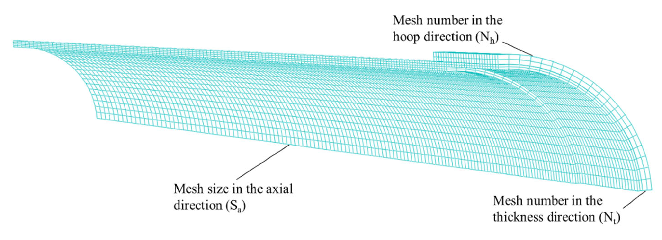
3.4. Model Verification and Mesh-Size Sensitivity

First, to verify the accuracy of the model, the same full-scale pipeline model as the test in [44] was established, and the buckling propagation and buckling crossing phenomena of the pipeline under the action of external pressure were observed. Figure 9 shows the comparison between the experimental results and the numerical simulation results. The numerical simulation reproduces the experimental situation well. The buckling of the pipeline passes through A1 and A2 successively, and the section of the pipeline presents a dumbbell shape during the propagation process and a U-shape when it passes through the CFRP.
Based on the numerical model described above, the collapse pressure was compared with Mahmoud’s experimental results [44]. It can be observed from Table 3 that the predicted collapse pressure is in good agreement with the experimental results, and most of the errors are within ±5%. In the following sections, the numerical models are applied for parametric studies. σLy is the lower yield stress, and σUu is the upper ultimate stress.
h is the thickness of CFRP, t is the thickness of the pipe wall, L is the longitudinal length of the CFRP, D is the pipe diameter, PXi is the result of experiment, PXS is the result of numerical simulation, Error is the deviation between numerical simulation and test results, and Error = (PXSPXi) ∗ 100%/PXi.
A meshing method with high accuracy and low computational cost was found through the different meshing of the model. Based on the geometry and loading characteristics, a 1/8 model was established to investigate the collapse pressure of the repaired pipes under external pressure. Mesh independence was determined before model verification, and the collapse pressure was used as the index of convergence. The results are summarized in Table 4, and the meanings of each parameter are shown in Figure 10: Nh is the mesh number in the hoop direction of the concrete jacket, Nt is the mesh number in the thickness direction of the CFRP and the steel pipe, Sa is the element size in the axial direction, and Pco is the collapse pressure.
It was observed that when the number of elements was increased from 9060 to 96,800, the collapse pressure deviation remained at 1%. Considering the accuracy and computational cost, No. 4 was used for further analysis.

4. Results and Discussion

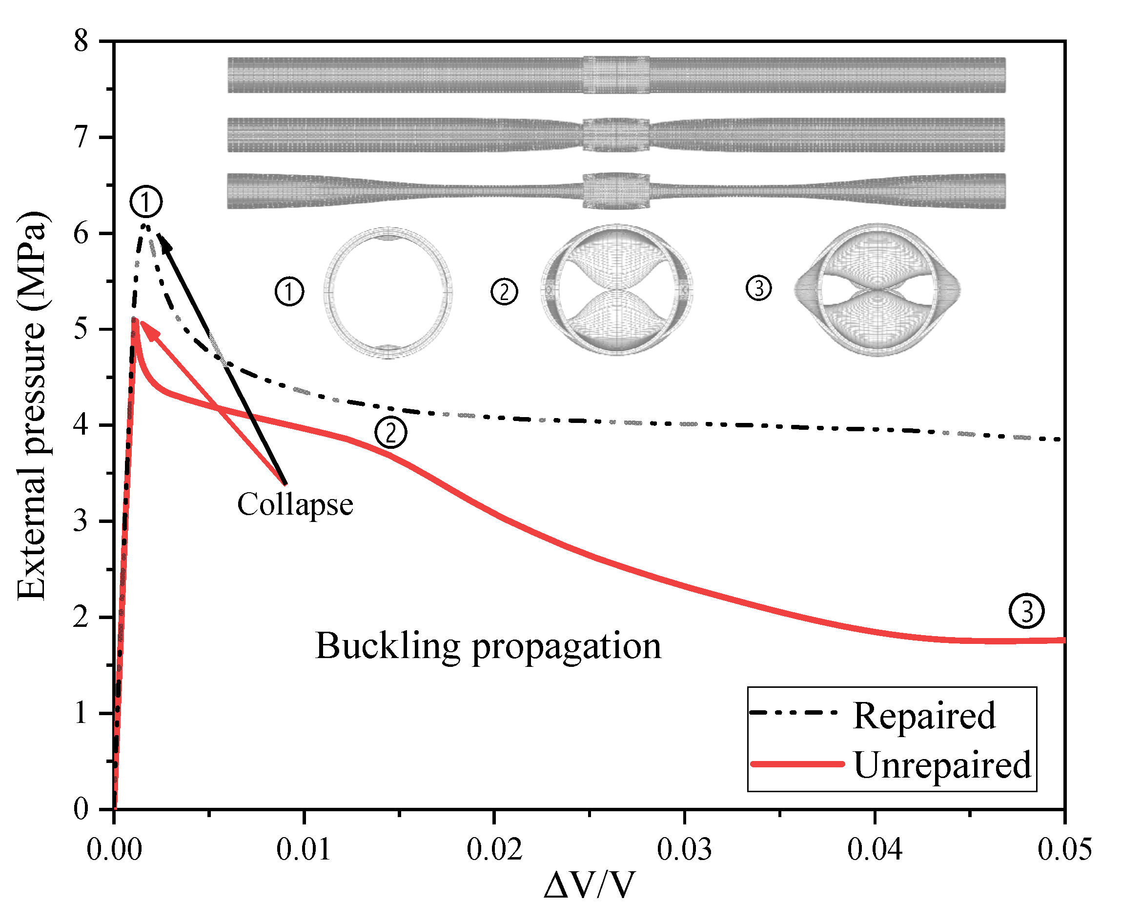
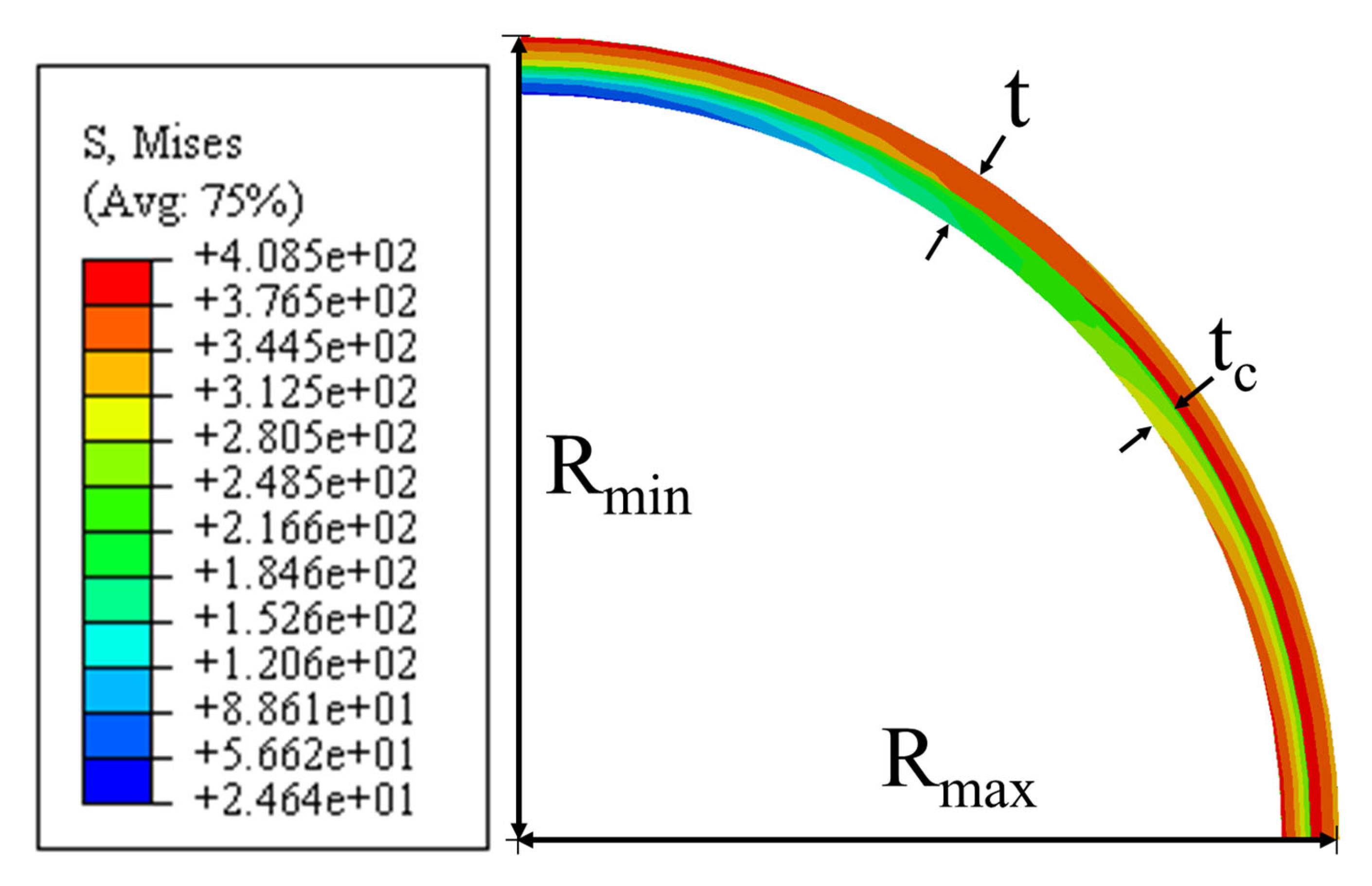
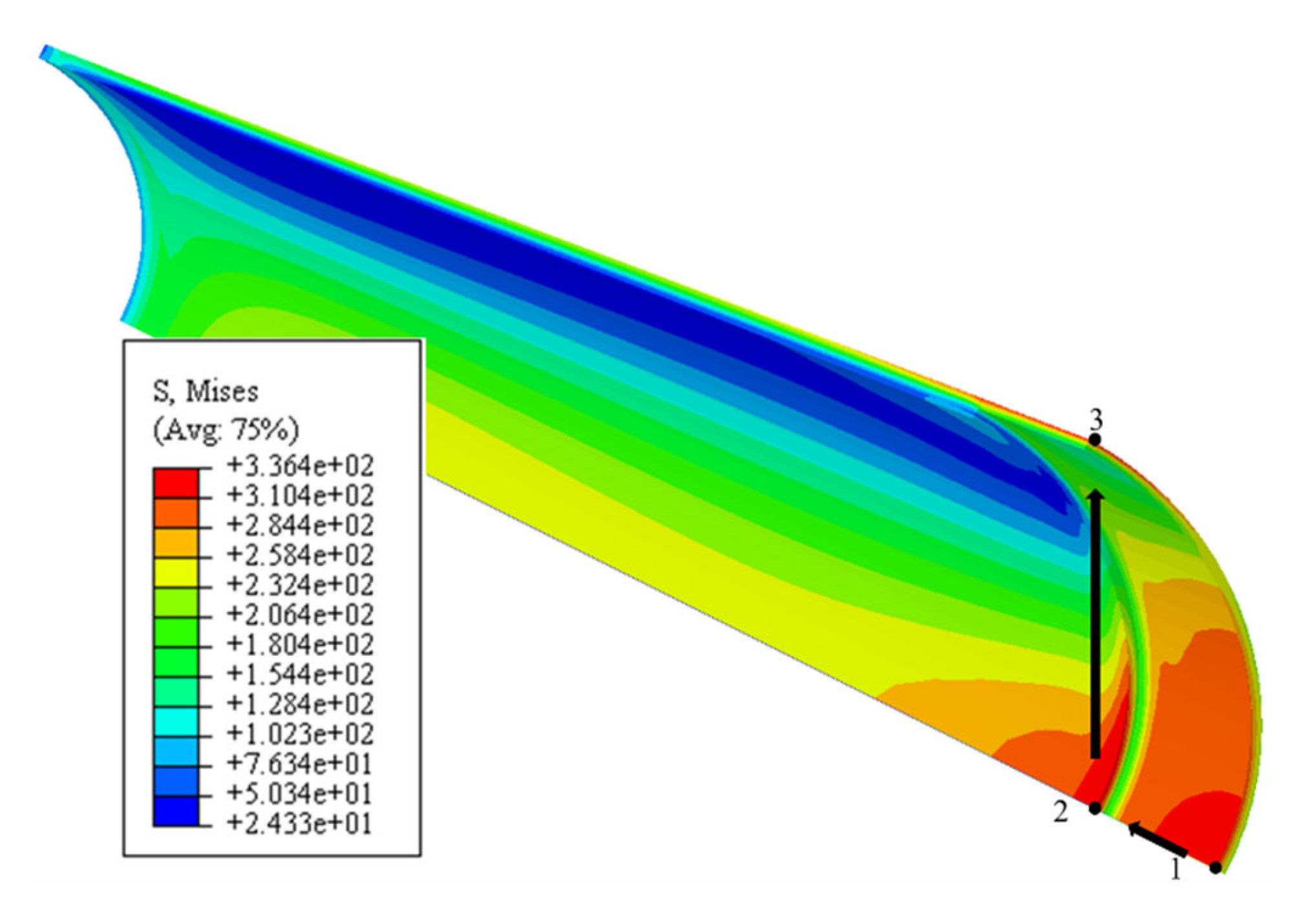
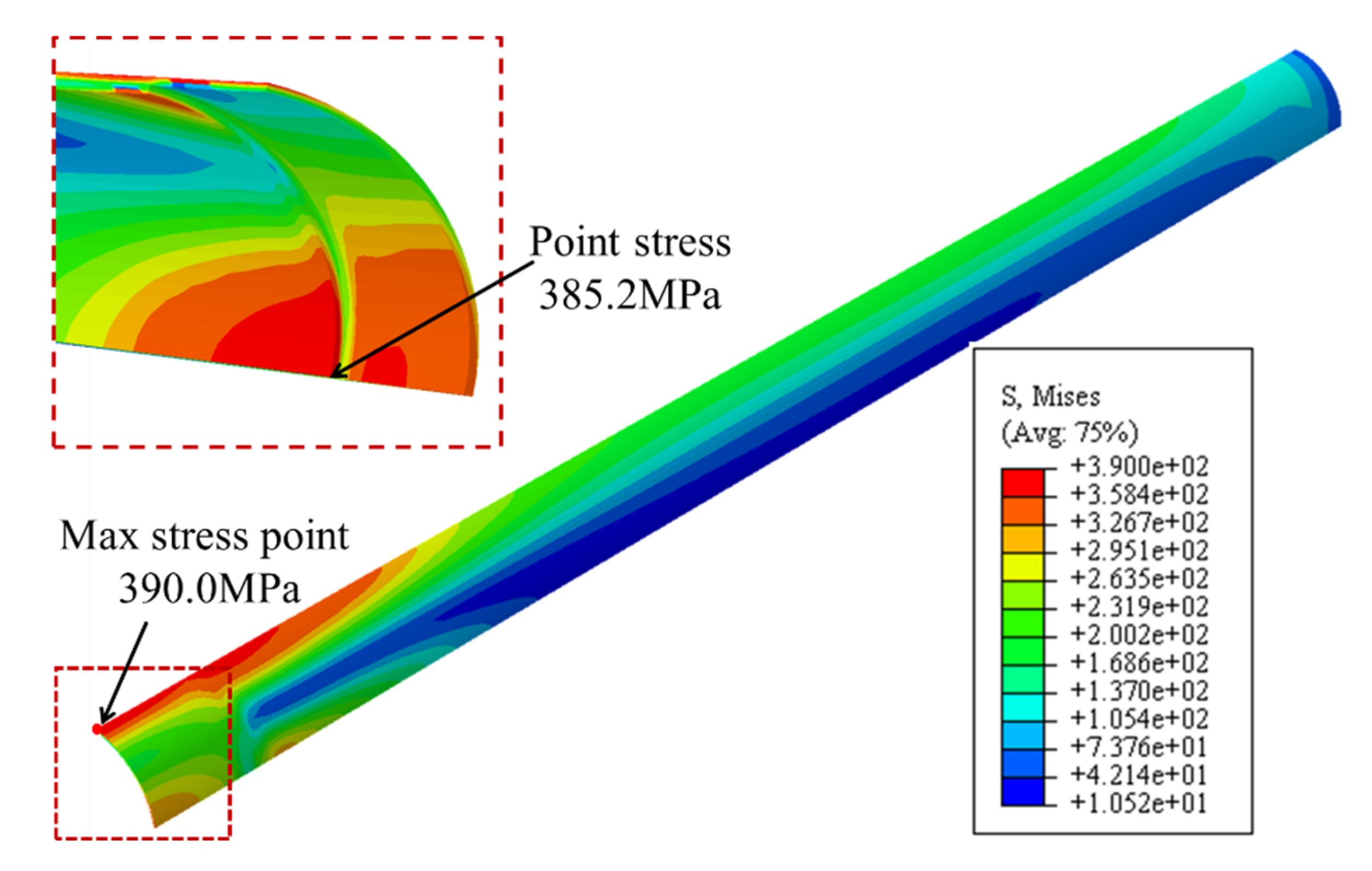
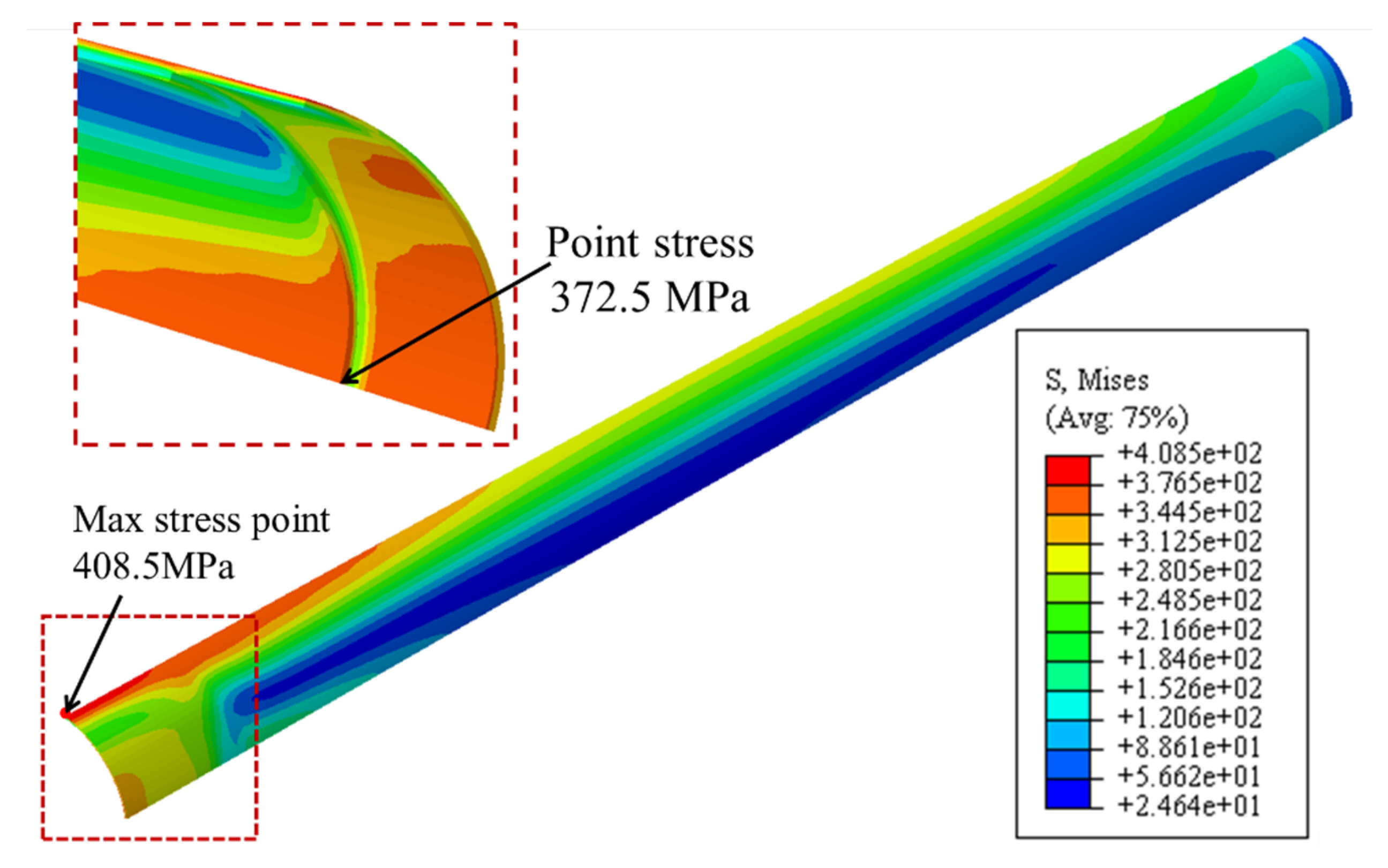
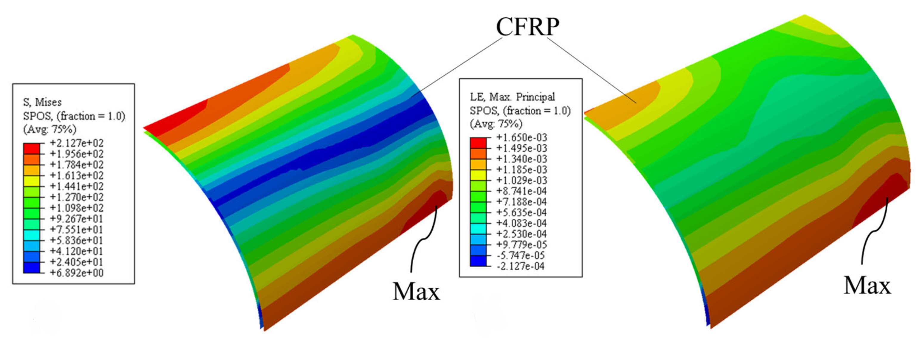
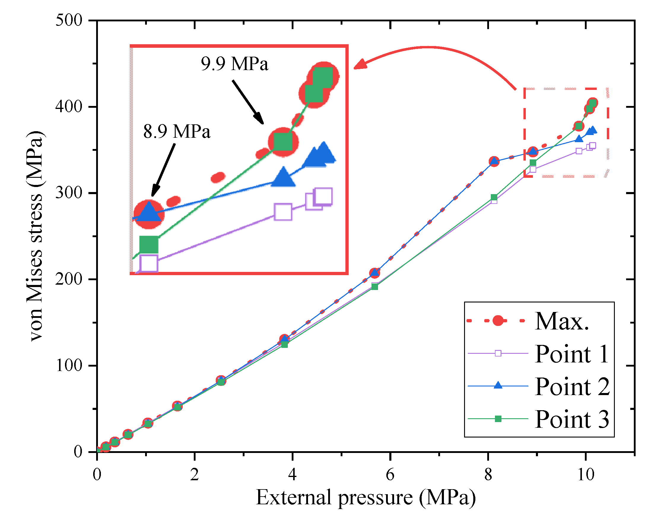
4.1. Stress Response under Ultimate External Pressure

CFRP significantly improves the pipe stress distribution and increases the maximum stress. In most cases, the occurrence of pipeline collapse is due to excessive stress in one or more locations. When the local stress of the pipeline exceeds the yield strength of the material, large deformation occurs in this part of the region. The deformation is generally caused by a small range of deformation, which drives the surrounding steel pipe to collapse in a larger area. The pipeline is subjected to external water pressure. Initially, due to its radial stiffness, the pipe can resist a part of the unstable force caused by the external water pressure due to the imperfect shape of the steel pipe.
However, when a large area of deformation occurs, the radial stiffness of the pipeline decreases and is not enough to support the external pressure; therefore, the pipeline becomes unstable, resulting in collapses. As shown in Figure 11, when the pipe is not repaired, the maximum stress of the steel pipe is located at the centre of the defect, reaching 390 MPa, which is similar to the yield strength of the steel pipe material.
The defects on the junction of the inner side of the steel pipe and the pipeline also have a large stress concentration, reaching 385.2 MPa. It can be seen that the collapse of the steel pipe is closely related to the yield strength of the steel pipe, and the authors of [5] have provided similar explanations. Figure 12 shows the stress distribution of the repaired pipeline at the maximum external water pressure. It can be seen from the highlighted areas in Figure 12 that the maximum stress on the pipeline reaches 408.5 MPa, which exceeds the yield strength of the steel. Similarly, there is stress concentration at the inner junction of the steel pipe, but the stress is smaller than it is for the unpaired pipeline, and the range of stress concentration is significantly larger than it is for the unpaired pipeline. The CFRP can effectively limit the local deformation of the pipeline and disperse the stress inside the pipeline.
To further study the repairing effect of CFRP on steel pipes, the stress distribution of carbon fibres was independently analysed. It can be seen from Figure 13 that when the external water pressure reaches 8.12 MPa, the stress above the middle of the defect and at the junction are larger than the unpaired pipelines, but both are significantly smaller than the failure strength of CFRP, while the interaction force between the steel pipe and the CFRP is uniform. As the pressure increases to 10.14 MPa, the maximum stress of the CFRP reaches 1650 MPa (less than the ultimate stress 1967.5 MPa), and the CFRP is damaged and deformed. The local failure of the CFRP is an important reason for the instability of the pipeline.
The influence of the interaction between the CFRP and steel pipe on the crushing pressure was further analysed through interlayer bonding. It is shown in Figure 14 that when the external pressure is 8.12 MPa, although the interlayer bonding is damaged, the stiffness of the bonding layer does not decrease, as shown in Figure 15.
When the external water pressure reaches the collapse pressure, a large area of bonding failure occurs in the centre of the defect, and the failure rate reaches 100%, while the stiffness damage only occurs in the middle position, and the damage degree reaches 37.29%. Therefore, the decrease in the stiffness of the interlayer bonding layer is an important factor that causes the local instability of the pipeline, and the ultimate bearing capacity of the repaired pipeline can be improved by improving the ductility and the maximum-failure tensile strength of the interlayer bonding.
The effect of the interlayer adhesion on the steel pipe was analysed above, and the interlayer contact was analysed to further determine the mechanism of the CFRP on the steel pipe. When the pressure was 5.68 MPa, the deformation of the steel pipe was small, and the contact stress with the CFRP was concentrated in the red box in Figure 16, which is the junction between the internal corrosion defect and the complete pipe section.
This stress concentration is mainly due to the deformation in the middle of the defect, and the steel pipes on both sides are in contact with the CFRP first. Since the elastic modulus of the CFRP is larger than that of the steel pipes, there is a large contact force at the junction. Figure 16 shows that when the pressure is increased to 10.14 MPa, the central part of the defect is obviously concave and deformed under collapse pressure, the defect is protruded outward as a whole, and more than half of the large area contact force appears. The CFRP limits the deformation of the pipeline very well.
The position of maximum contact force is located at the junction of the defect and the pipe section. Therefore, the effect of the CFRP on the pipeline is mainly to limit the deformation at the junction of the defect and the complete pipe segment through the contact force, increasing the local radial stiffness of the pipeline. Defective pipes with internal thinning are restrained from deformation by contact between the CFRP and the steel pipe.

4.2. Stress–Time History Response Analysis

In this section, the repairing effect of CFRP on steel pipes is investigated by analysing the stress changes in the pipes during the test. Figure 17 shows the 1/4 section of the steel pipe. In Figure 18, the relationship between the two and the effect on the collapse pressure of the pipe are explored through an analysis of the maximum stress and maximum ovality of the pipe. The ovality is defined by the following formula:
Δ = R max R min R max + R min × 100 %
where Rmax represents the maximum radius of the pipeline, and Rmin represents the minimum diameter of the pipeline. The initial ovality at the pipe section is 1%.
CFRP significantly enhances the external pressure resistance of the pipeline and reduces the ovality when the pipeline is crushed. As shown in Figure 18, the maximum stress and ovality of the steel pipe before and after repair both increase with the increase in external pressure. Before the repair, when the external pressure reached 7.84 MPa, the ovality in the middle of the pipeline defect was 4.08%, and the maximum stress of the repaired pipeline reached 404.67 MPa, which was higher than the maximum stress of 385.18 MPa before the repair. Therefore, when the external pressure reached 10.15 MPa, the local stress of the repaired pipeline exceeded the yield strength of the steel pipe material. However, there is no large-scale collapse due to the limitation in CFRP. According to previous studies, the collapse pressure of the pipeline is positively correlated with the ovality. Therefore, CFRP increases the radial stiffness of the pipeline and the stability of the defect parts, limits the deformation of the steel pipe, and improves the overall stability of the pipeline.
In the above analysis, it was found that the maximum stress of the repaired steel pipe does not increase uniformly with the increase in the external pressure. To explore this phenomenon and make corrections to the future CFRP manufacturing process, this section analyses the change in the maximum stress point of the steel pipe.
As shown in Figure 19, the external pressure–stress curves for points one, two, and three are extracted, respectively. It can be found from Figure 20 that the initial stress concentration of the steel tube occurs at point one. This shows that when the external water pressure is small, the middle position of the pipeline defect is most prone to deformation. Currently, the interaction force between the CFRP and the steel pipe is still very small. When the external pressure is greater than 2.54 MPa, the maximum stress of the steel pipe appears at point two. This shows that the CFRP has begun to limit the deformation of the defective pipe section. At this time, the overall strength of the defect is increased, the defect pipeline will not have local large deformation, and the stress concentration position will appear at the junction of the defect and the complete pipe section. When the external water pressure is 8.9–9.9 MPa, the maximum stress of the steel pipe changes from point two to point three. It can be seen from Figure 20 that point three maintains a linear increase before crushing, while the stress at point two increases at a slower rate of 8.12 MPa. This is because the bond between the CFRP and the steel pipe is damaged, the bond force at the centre of the pipe defect decreases, and the force on the compressed parts on both sides continues to increase. When the external water pressure is greater than 9.9 MPa, the maximum stress of the pipeline is concentrated in the depression in the centre of the defect position, and the stability of the steel pipe is greatly reduced by this external pressure. The central area undergoes large deformation due to the decrease in the bond strength. CFRP can effectively disperse the stress concentration when the water pressure is small, and the stress at the concave position of the pipeline is no longer a dangerous point in the pipeline. CFRP can significantly improve the stress concentration of steel pipes and delay the occurrence of pipeline collapse.

5. Influential Factors

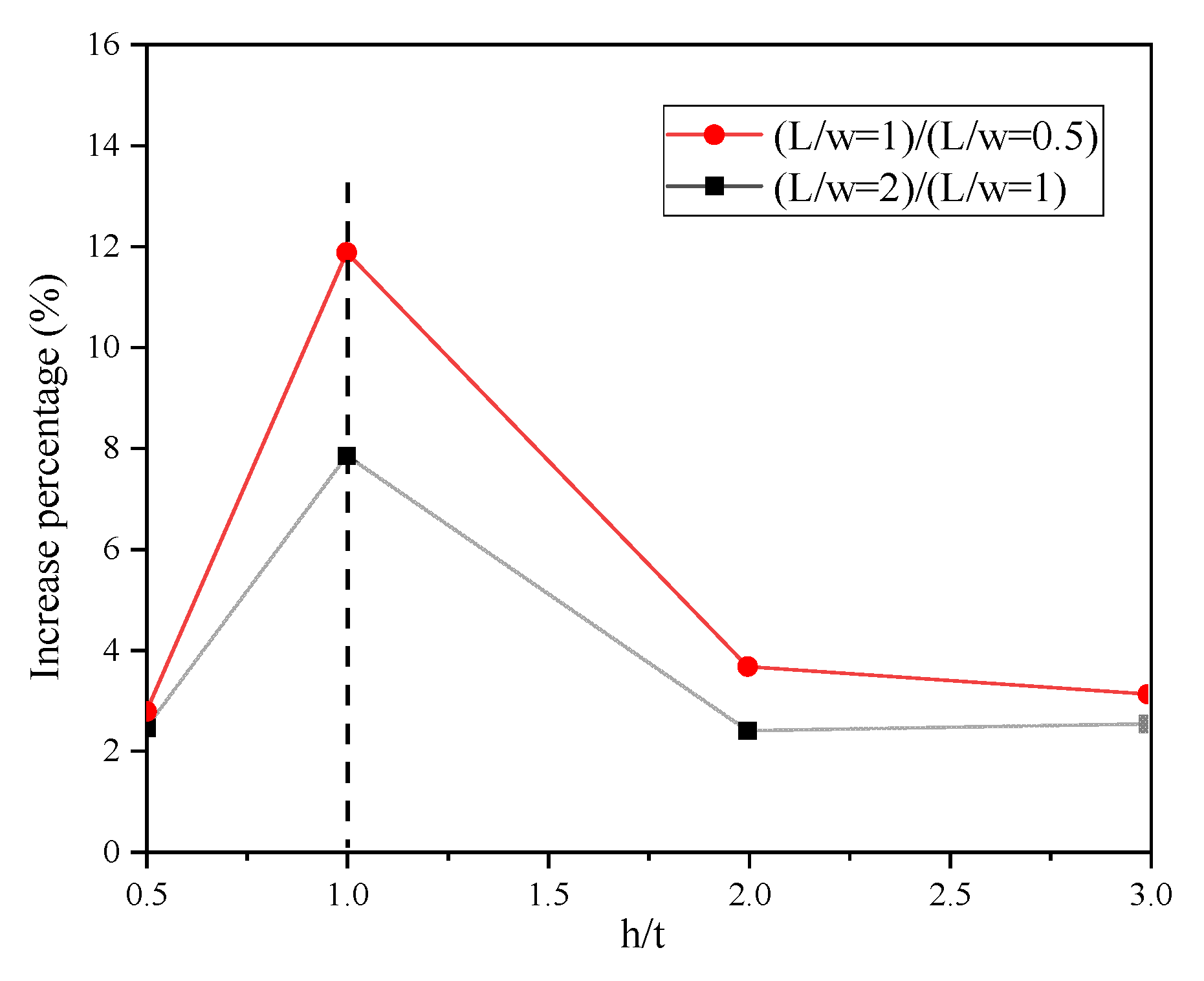
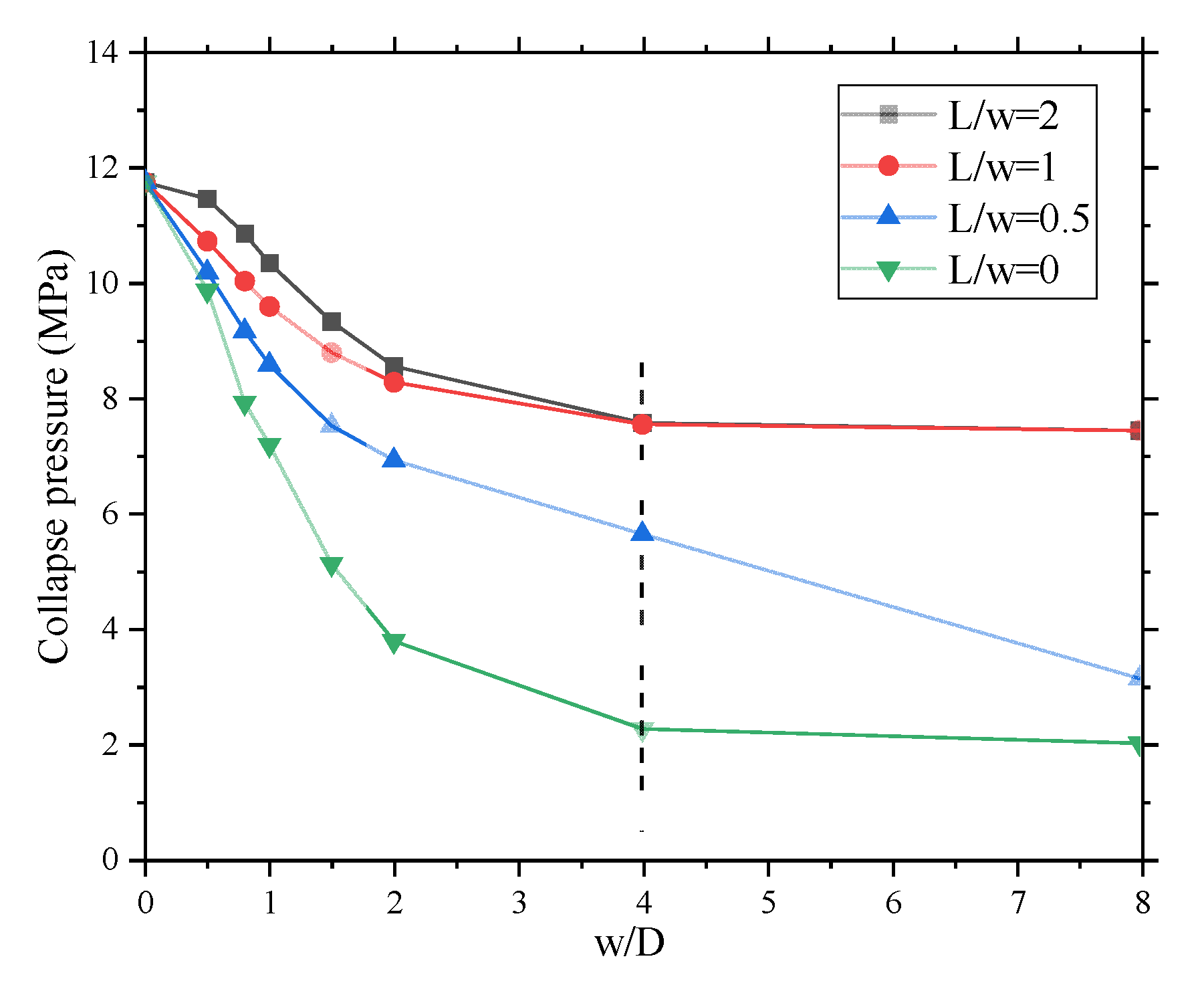
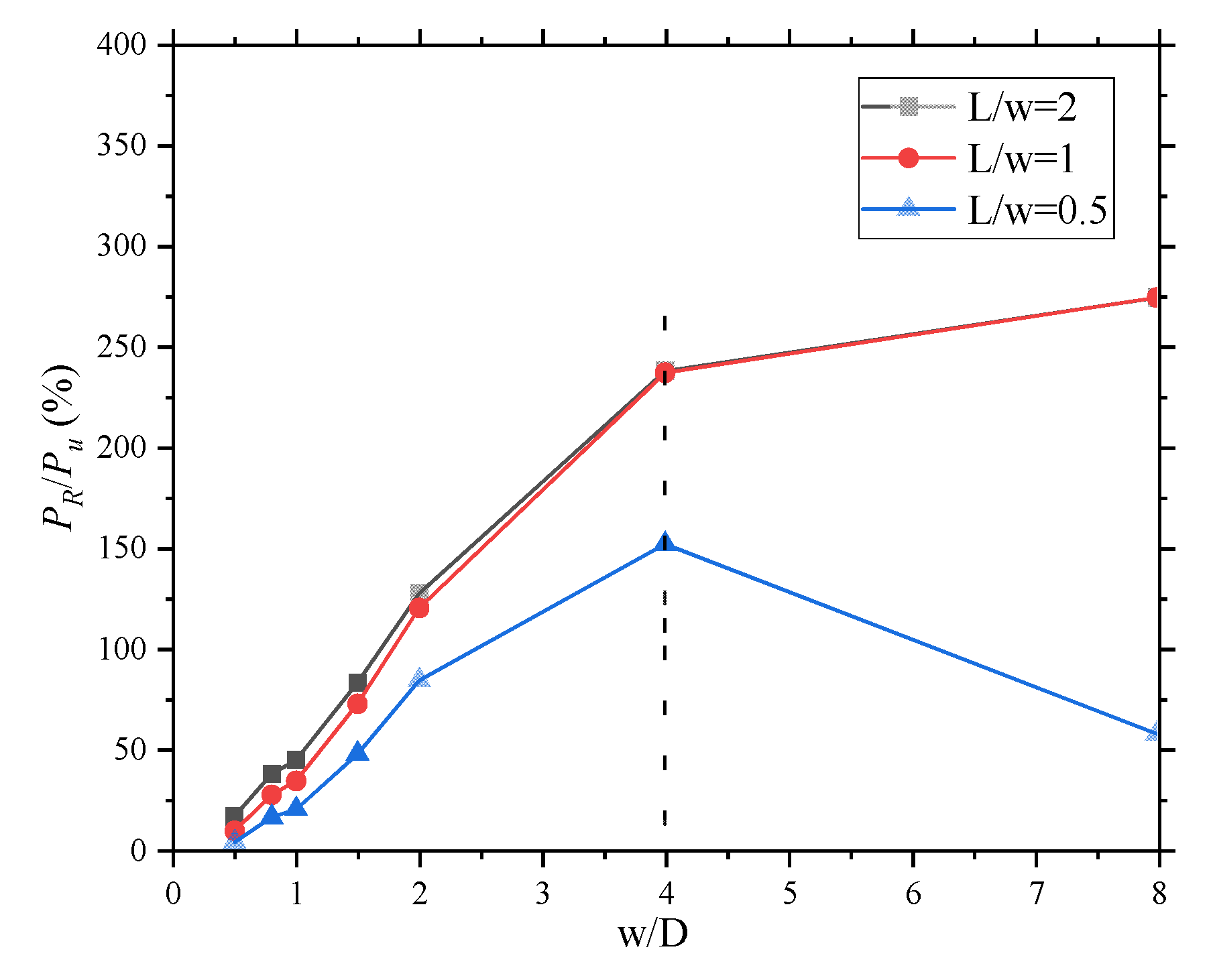
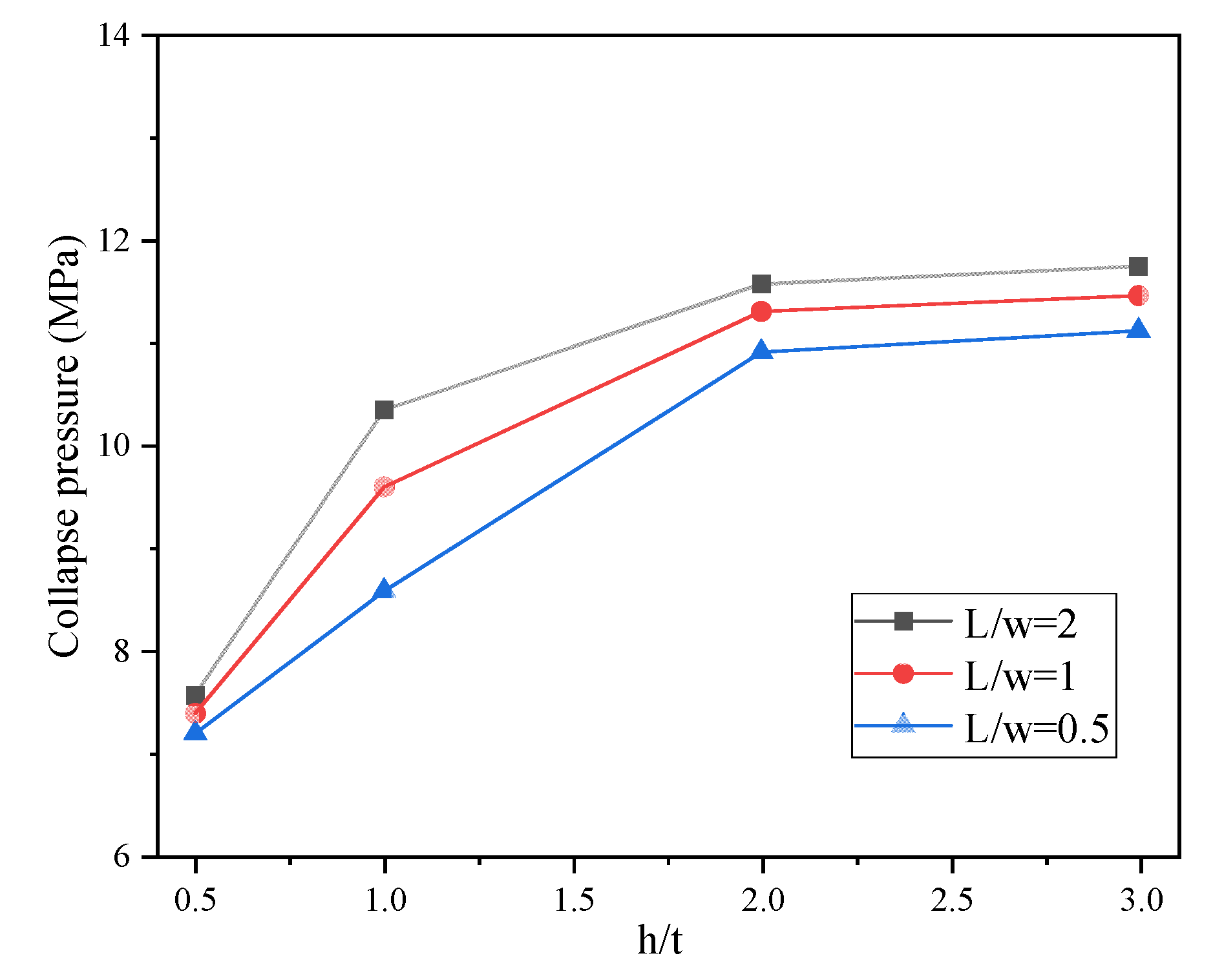
5.1. Longitudinal Length of Defect and CFRP

The length of the defect influences the repair effect of the pipeline. As shown in Figure 21, the repaired pipe does not fully restore the strength of the pipe. The curve of L/w = 0 indicates that the collapse pressure of unrepaired pipe decreases with the increase in defect length. When the ratio of the pipeline defect length to diameter w/D > 4, the change in pipeline collapse pressure decreases. The same phenomenon is observed when CFRP fully covers the pipeline defect location. However, if the CFRP does not fully cover the defect position, the collapse pressure of the pipeline will still decrease with the increase in the defect length.
The repair effect of CFRP is not linearly enhanced. As shown in Figure 22, when the defect length/diameter w/D < 2, the increase in the CFRP length can significantly increase the collapse pressure of the pipeline. However, when L/w > 2, the effect of CFRP is small, and the effect of increasing the length of the CFRP is not significant. It can be seen from the data analysis that the collapse pressure of the repaired pipeline is 3.1–274% higher than that of the pipeline before repair. When L/w is less than two, the collapse pressure of the repaired pipe decreases with the increase in defect width. The repair effect increases gradually from 3.1% and reaches the highest when w/D = 4. When w/D is greater than four, the collapse pressure can be increased to 65% of the pipe without defect, which is 274% higher than the unpaired pipe. When the CFRP length is greater than the defect length, the repair effect is similar. When the defect length is less than the diameter, the collapse pressure of the repaired pipeline can reach 72.98–97.53% of the initial external pressure capacity. However, as shown in Figure 22, when the defect length of the pipeline is greater than the CFRP, and the defect length is less than four times the diameter, the repair effect increases with the increase in the defect length; when the defect length is greater than four times the diameter, the repair effect increases. The effect decreases when the defect length increases.

5.2. Metal Loss Rate

In this section, the influence of different degrees of defects on the repair effect is analysed. tc/t refers to the defect wall thickness/wall thickness. The model used is L/w = 1, w/D = 4. The thickness of the CFRP is 0.5–3 times the wall thickness of the steel pipe, and the wall thickness at the defect is 0.3–0.8 times the wall thickness before corrosion. As shown in Figure 23, when the CFRP thickness is greater than the pipe wall thickness, the repair effect for defects with tc/t < 0.3 differs by 3.09%. When the CFRP thickness is twice the pipe wall thickness, the repair effect is almost the same. For pipes with large wall thickness defects, increasing the thickness of the CFRP has no obvious effect. For steel pipes with small defects, if the thickness tc/t of the defected part is greater than 0.3, increasing the thickness of the CFRP can effectively improve the repair efficiency. It can be seen from the bottom two curves in Figure 23 that when h/t = 0.5, the ultimate bearing capacity of the pipeline is increased by less than 1%.
When the tc/t defect wall thickness/wall thickness is less than 0.3, increasing the CFRP thickness cannot significantly improve the repair effect; when the ratio of the tc/t defect wall thickness and the wall thickness is greater than 0.3, increasing the CFRP wall thickness can improve the ultimate bearing capacity of the repaired pipeline. When the CFRP wall thickness is two times the steel pipe wall thickness, the repair efficiency is the highest, tc/t is greater than 0.5, and the ultimate bearing capacity of the pipeline after repair is the same as before the repair.

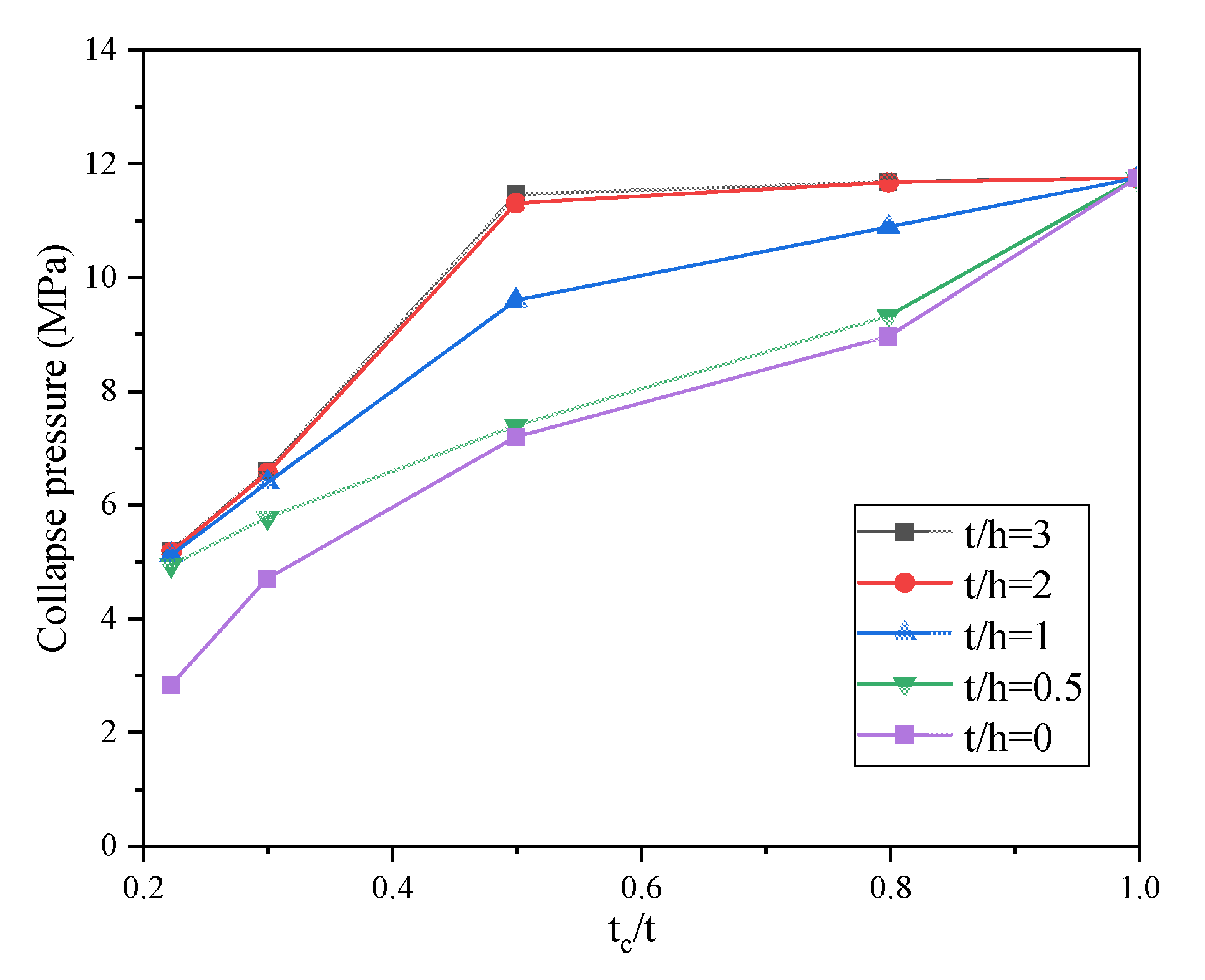
5.3. Thickness of CFRP

In this section, the effects of different sizes of CFRP are analysed. The adopted model is L/w = 0.5–2, h/t = 0.5–3. The thickness of the CFRP is 0.5–3 times the wall thickness of the steel pipe, and the length is 0.5–2 times the length of the defect. As shown in Figure 24, the collapse pressure of the repaired pipeline gradually increases as the thickness of the CFRP increases. Therefore, the greater the thickness, the better the effect of the repair. The repair efficiency has a nonlinear relationship with the length of the CFRP, as shown in Figure 25: when the length of the CFRP is the same as the pipeline defect, the repair efficiency is the highest. When the CFRP length is greater than the defect length, the repair effect decreases with the increase in thickness. When the CFRP thickness is the same as the pipe thickness, increasing the CFRP length can significantly improve the repair efficiency. Therefore, when the thickness of the CFRP is larger than the thickness of the steel pipe wall, the repair effect is not significantly improved.

6. Conclusions

This study investigated the buckling failure of internally corroded steel pipes repaired using the CFRP. The repaired internally corroded pipeline was analysed using the three-dimensional elastic–plastic finite element method. The collapse phenomenon of the repaired steel pipe under external hydrostatic pressure was simulated using the cohesive element and energy criterion. The results show that the CFRP thickness and length can change the collapse pattern and the pipeline’s stress distribution. A decrease in the ovality with corrosion defects was observed, and it was found that the repair of CFRP mainly depends on the length, thickness, and interlayer cohesion. From the above results, the following conclusions can be drawn:
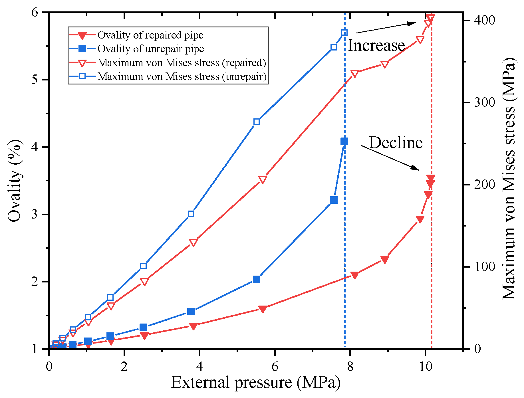
  • CFRP limits the deformation at the junction of defects and complete pipe segments, thereby increasing the local radial stiffness of the pipe and the stability of the defect parts. The interaction of CFRP with the steel pipe causes the deformation at the defects of the steel pipe to be limited by the uncorroded pipe. CFRP can effectively limit the local deformation of the pipeline and disperse the stress inside it, which improves the pipeline’s overall stability.
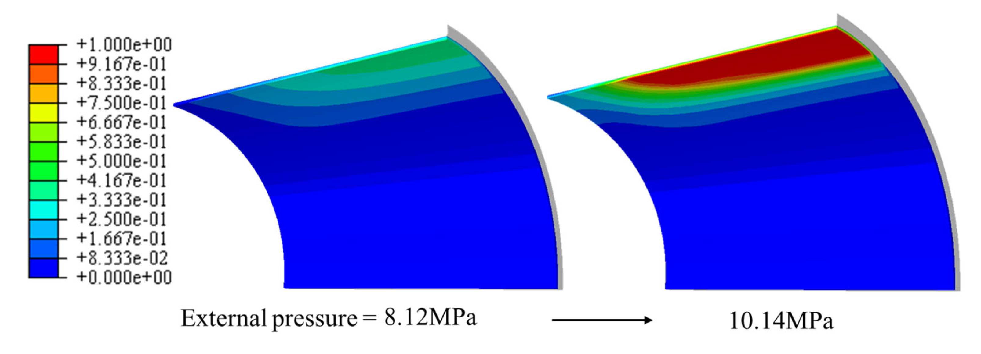
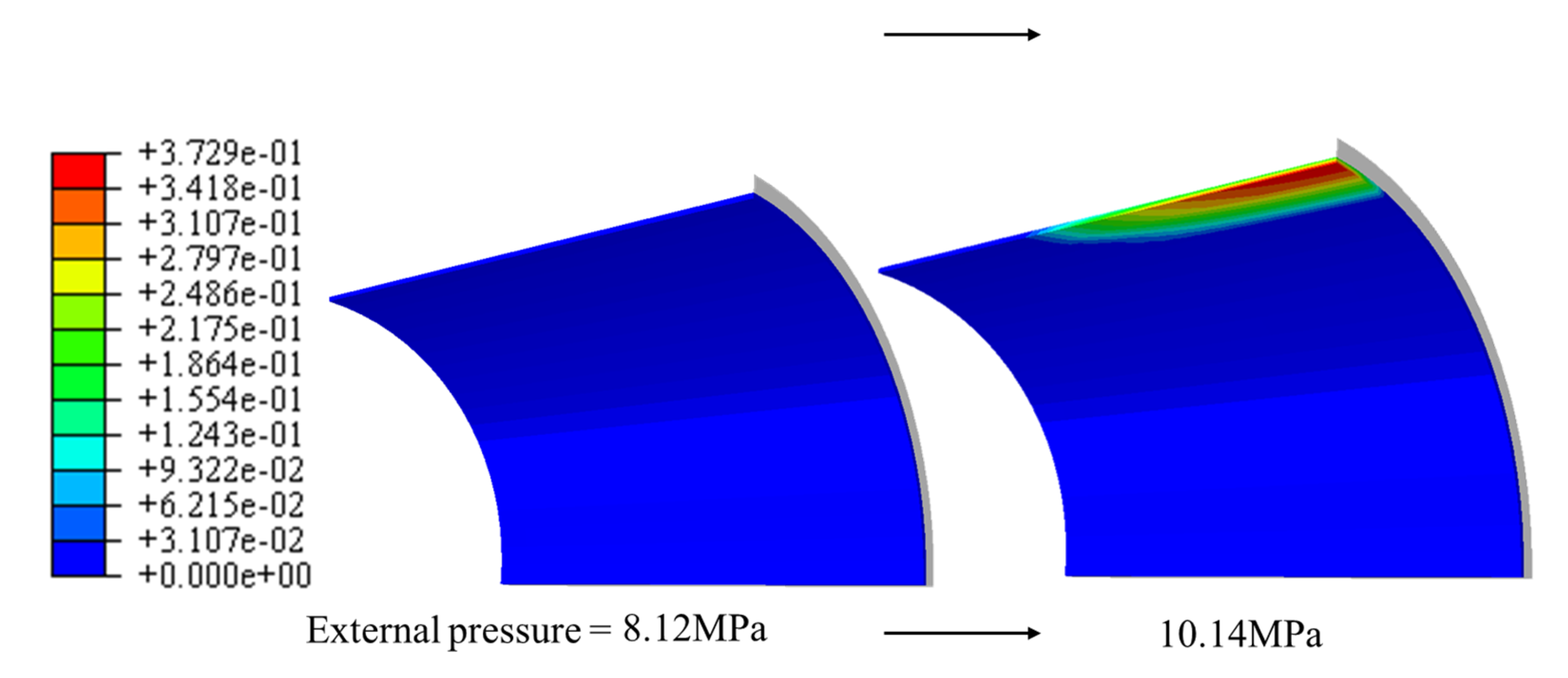
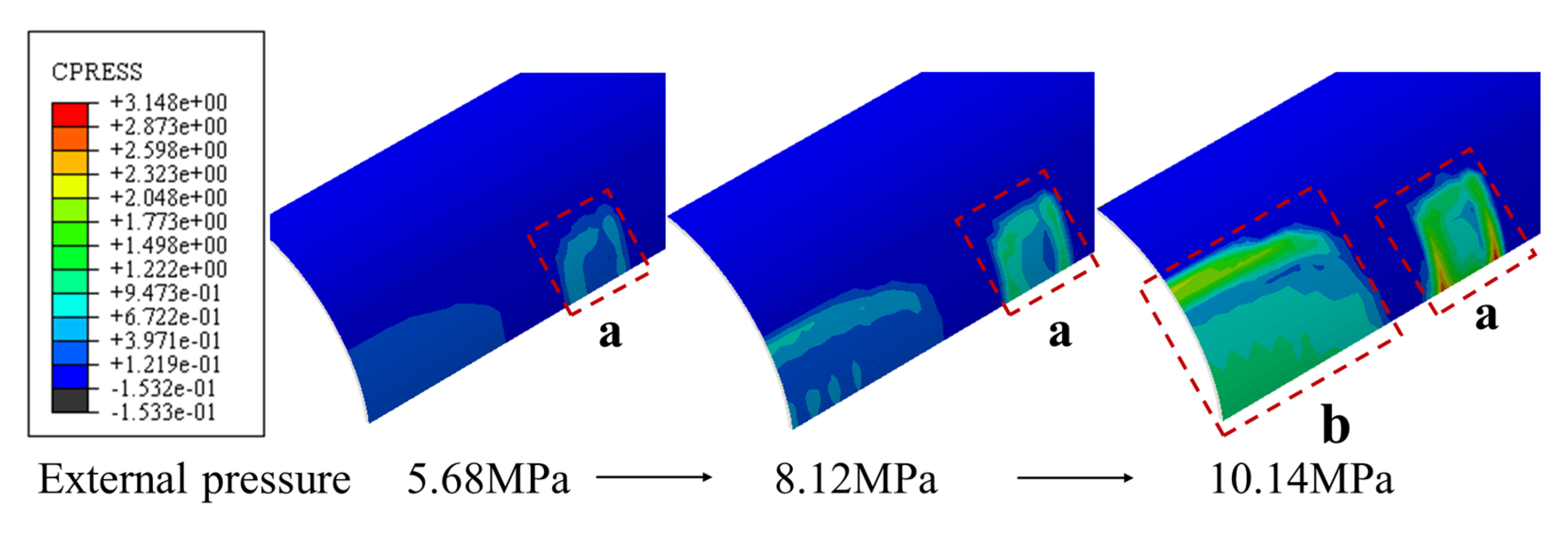
  • CFRP disperses the stress concentration well when the water pressure is small and the stress at the concave position of the pipeline is no longer a dangerous point of the pipeline. CFRP can significantly improve the stress concentration of steel pipes and delay the occurrence of pipeline collapse. Local CFRP failure is an important cause of pipeline instability.
  • The decrease in stiffness of the interlayer bonding layer is an important factor that causes the local instability of the pipeline, and the ultimate bearing capacity of the repaired pipeline can be improved by improving the ductility and the maximum-failure tensile force of the interlayer bonding.
  • When the defect length is less than the diameter, the collapse pressure of the repaired pipeline can reach 72.98–97.53%, and the repair effect increases with the increase in CFRP length. When the defect length is less than the CFRP length and the defect length is less than four times the diameter, the crushing pressure of the repaired pipeline is increased by 3.1–274%, and the repair effect increases with the increase in the defect length. When the defect length is greater than four times the diameter, the repair effect decreases with the increase in the defect length.
  • When the defect wall thickness/steel wall thickness is less than 0.3, increasing the CFRP thickness cannot significantly improve the repair effect; when the ratio of the tc/t defect wall thickness and the wall thickness is greater than 0.3, increasing the CFRP wall thickness can improve the ultimate bearing capacity of the repaired pipeline. When the CFRP wall thickness is two times the steel pipe wall’s thickness, the repair efficiency is the highest, and the bearing limit of the pipeline after repair can reach 100%. When it is more than two times the steel pipe wall’s, it has no obvious effect on the bearing limit after the repair. If the ratio of the wall thickness of the defect and the wall thickness of the steel pipe is greater than 0.5, the ultimate bearing capacity of the pipeline after repair is the same as before the repair.

Author Contributions

Conceptualization, J.Y., W.X. and Y.Y.; methodology, J.Y., W.X. and Y.Y.; software, W.X., Y.Y., F.F. and H.W.; validation, W.X., Y.Y., F.F. and H.W.; formal analysis, S.X. and S.W.; investigation, S.X. and S.W.; resources, F.F.; data curation, F.F.; writing—original draft preparation, W.X. and Y.Y.; writing—review and editing, F.F., H.W., S.X. and S.W.; visualization, J.Y.; supervision, J.Y.; project administration, J.Y.; funding acquisition, J.Y., Y.Y. and F.F. All authors have read and agreed to the published version of the manuscript.

Funding

This research is supported by Guangxi Zhuang Autonomous Region Bagui Scholars Program and the National Natural Science Foundation of China (Grant No. 52071234, Grant No. 51879189).

Institutional Review Board Statement

Not applicable.

Informed Consent Statement

Not applicable.

Conflicts of Interest

The authors declare that they have no known competing financial interests or personal relationships that could have appeared to influence the work reported in this paper.

References

  1. Yun, H.D.; Peek, R.R.; Paslay, P.R.; Kopp, F.F. Loading History Effects for Deep-Water S-Lay of Pipelines. J. Offshore Mech. Arct. Eng. 2004, 126, 156–163. [Google Scholar] [CrossRef]
  2. Xie, P.; Zhao, Y.; Yue, Q.; Palmer, A.C. Dynamic loading history and collapse analysis of the pipe during deepwater S-lay operation. Mar. Struct. 2015, 40, 183–192. [Google Scholar] [CrossRef]
  3. Yuan, L.; Kyriakides, S. Liner wrinkling and collapse of bi-material pipe under axial compression. Int. J. Solids Struct. 2015, 60–61, 48–59. [Google Scholar] [CrossRef]
  4. Kyriakides, S. Effects of Reeling on Pipe Structural Performance—Part I: Experiments. J. Offshore Mech. Arct. Eng. 2017, 139, 051706. [Google Scholar] [CrossRef]
  5. Dyau, J.Y.; Kyriakides, S. On the localization of collapse in cylindrical shells under external pressure. Int. J. Solids Struct. 1993, 30, 463–482. [Google Scholar] [CrossRef]
  6. Sakakibara, N.; Kyriakides, S.; Corona, E. Collapse of partially corroded or worn pipe under external pressure. Int. J. Mech. Sci. 2008, 50, 1586–1597. [Google Scholar] [CrossRef]
  7. Netto, T.A. A simple procedure for the prediction of the collapse pressure of pipelines with narrow and long corrosion defects—Correlation with new experimental data. Appl. Ocean Res. 2010, 32, 132–134. [Google Scholar] [CrossRef]
  8. Ramasamy, R.; Ya, T.T. Nonlinear finite element analysis of collapse and post-collapse behaviour in dented submarine pipelines. Appl. Ocean Res. 2014, 46, 116–123. [Google Scholar] [CrossRef]
  9. Wang, H.; Yu, Y.; Yu, J.; Jin, C.; Zhao, Y.; Fan, Z.; Zhang, Y. Effect of 3D random pitting defects on the collapse pressure of pipe—Part II: Numerical analysis. Thin-Walled Struct. 2018, 129, 527–541. [Google Scholar] [CrossRef]
  10. Wang, H.; Yu, Y.; Yu, J.; Duan, J.; Zhang, Y.; Li, Z.; Wang, C. Effect of 3D random pitting defects on the collapse pressure of pipe—Part I: Experiment. Thin-Walled Struct. 2018, 129, 512–526. [Google Scholar] [CrossRef]
  11. Wang, H.; Yu, Y.; Xu, W.; Li, Z.; Yu, S. Time-variant burst strength of pipe with corrosion defects considering mechano-electrochemical interaction. Thin-Walled Struct. 2021, 169, 108479. [Google Scholar] [CrossRef]
  12. Junior, N.M.; Carrasquila, A.; Figueiredo, A.A.; da Fonseca, C. Worn pipes collapse strength: Experimental and numerical study. J. Pet. Sci. Eng. 2015, 133, 328–334. [Google Scholar] [CrossRef]
  13. Zhang, X.; Pan, G. Collapse of thick-walled subsea pipelines with imperfections subjected to external pressure. Ocean Eng. 2020, 213, 107705. [Google Scholar] [CrossRef]
  14. Chen, B.-Q.; Zhang, X.; Soares, C.G. The effect of general and localized corrosions on the collapse pressure of subsea pipelines. Ocean Eng. 2022, 247, 110719. [Google Scholar] [CrossRef]
  15. Chen, Y.; Dong, S.; Zang, Z.; Ao, C.; Liu, H.; Gao, M.; Ma, S.; Zhang, E.; Cao, J. Buckling analysis of subsea pipeline with idealized corrosion defects using homotopy analysis method. Ocean Eng. 2021, 234, 108865. [Google Scholar] [CrossRef]
  16. Yu, J.; Xu, W.; Yu, Y.; Wang, H.; Li, H.; Xu, S.; Han, M. Effectiveness of concrete grouting method for deep-sea pipeline repairs. Thin-Walled Struct. 2021, 169, 108336. [Google Scholar] [CrossRef]
  17. Johns, T.G.; Mesloh, R.E.; Sorenson, J.E.; Laboratories, B.C. Propagating Buckle Arrestors for Offshore Pipelines. J. Press. Vessel Technol. 1978, 100, 206–214. [Google Scholar] [CrossRef]
  18. Hahn, G.D.; She, M.; Carney, J.F. Buckle propagation and arresting in offshore pipelines. Thin-Walled Struct. 1994, 18, 247–260. [Google Scholar] [CrossRef]
  19. Lee, L.-H.; Kyriakides, S. On the arresting efficiency of slip-on buckle arrestors for offshore pipelines. Int. J. Mech. Sci. 2004, 46, 1035–1055. [Google Scholar] [CrossRef]
  20. Netto, T.A.; Kyriakides, S. Dynamic performance of integral buckle arrestors for offshore pipelines. Part I: Experiments. Int. J. Mech. Sci. 2000, 42, 1405–1423. [Google Scholar] [CrossRef]
  21. Netto, T.A.; Kyriakides, S. Dynamic performance of integral buckle arrestors for offshore pipelines. Part II: Analysis. Int. J. Mech. Sci. 2000, 42, 1425–1452. [Google Scholar] [CrossRef]
  22. Lee, L.-H.; Kyriakides, S.; Netto, T.A. Integral buckle arrestors for offshore pipelines: Enhanced design criteria. Int. J. Mech. Sci. 2008, 50, 1058–1064. [Google Scholar] [CrossRef]
  23. Bardi, F.; Kyriakides, S. Plastic buckling of circular tubes under axial compression—Part I: Experiments. Int. J. Mech. Sci. 2006, 48, 830–841. [Google Scholar] [CrossRef]
  24. Bruce, W.A. Comparison of Fiber-Reinforced Polymer Wrapping Versus Steel Sleeves for Repair of Pipelines; Elsevier: Amsterdam, The Netherlands, 2015; ISBN 9780857096920. [Google Scholar]
  25. Farag, M.H.; Mahdi, E. New approach of pipelines joining using fiber reinforced plastics composites. Compos. Struct. 2019, 228, 111341. [Google Scholar] [CrossRef] [Green Version]
  26. Lim, K.S.; Azraai, S.N.A.; Yahaya, N.; Noor, N.M.; Zardasti, L.; Kim, J.-H.J. Behaviour of steel pipelines with composite repairs analysed using experimental and numerical approaches. Thin-Walled Struct. 2019, 139, 321–333. [Google Scholar] [CrossRef]
  27. Yu, J.; Xu, W.; Chen, N.-Z.; Jiang, S.; Xu, S.; Li, H.; Han, M. Effect of dent defects on the collapse pressure of sandwich pipes. Thin-Walled Struct. 2022, 170, 108608. [Google Scholar] [CrossRef]
  28. Sun, C.; Mao, D.; Zhao, T.; Shang, X.; Wang, Y.; Duan, M. Investigate Deepwater Pipeline Oil Spill Emergency Repair Methods. Aquat. Procedia 2015, 3, 191–196. [Google Scholar] [CrossRef]
  29. Keller, M.W.; Jellison, B.D.; Ellison, T. Moisture effects on the thermal and creep performance of carbon fiber/epoxy composites for structural pipeline repair. Compos. Part B Eng. 2013, 45, 1173–1180. [Google Scholar] [CrossRef]
  30. Wonderly, C.; Grenestedt, J.; Fernlund, G.; Cěpus, E. Comparison of mechanical properties of glass fiber/vinyl ester and carbon fiber/vinyl ester composites. Compos. Part B Eng. 2005, 36, 417–426. [Google Scholar] [CrossRef]
  31. Lukács, J.; Nagy, G.; Török, I.; Égert, J.; Pere, B. Experimental and numerical investigations of external reinforced damaged pipelines. Procedia Eng. 2010, 2, 1191–1200. [Google Scholar] [CrossRef] [Green Version]
  32. Xu, X.; Shao, Y.; Gao, X.; Mohamed, H.S. Stress concentration factor (SCF) of CHS gap TT-joints reinforced with CFRP. Ocean Eng. 2022, 247, 110722. [Google Scholar] [CrossRef]
  33. Kong, D.; Huang, X.; Xin, M.; Xian, G. Effects of defect dimensions and putty properties on the burst performances of steel pipes wrapped with CFRP composites. Int. J. Press. Vessel. Pip. 2020, 186, 104139. [Google Scholar] [CrossRef]
  34. Elchalakani, M. Rehabilitation of corroded steel CHS under combined bending and bearing using CFRP. J. Constr. Steel Res. 2016, 125, 26–42. [Google Scholar] [CrossRef]
  35. Elchalakani, M.; Karrech, A.; Basarir, H.; Hassanein, M.F.; Fawzia, S. CFRP strengthening and rehabilitation of corroded steel pipelines under direct indentation. Thin-Walled Struct. 2017, 119, 510–521. [Google Scholar] [CrossRef] [Green Version]
  36. Mohamed, H.S.; Shao, Y.; Chen, C.; Shi, M. Static strength of CFRP-strengthened tubular TT-joints containing initial local corrosion defect. Ocean Eng. 2021, 236, 109484. [Google Scholar] [CrossRef]
  37. Mokhtari, M.; Nia, A.A. The influence of using CFRP wraps on performance of buried steel pipelines under permanent ground deformations. Soil Dyn. Earthq. Eng. 2015, 73, 29–41. [Google Scholar] [CrossRef]
  38. Shamsuddoha; Manalo, A.; Aravinthan, T.; Islam, M.; Djukic, L. Failure analysis and design of grouted fibre-composite repair system for corroded steel pipes. Eng. Fail. Anal. 2021, 119, 104979. [Google Scholar] [CrossRef]
  39. Meriem-Benziane, M.; Abdul-Wahab, S.A.; Zahloul, H.; Babaziane, B.; Hadj-Meliani, M.; Pluvinage, G. Finite element analysis of the integrity of an API X65 pipeline with a longitudinal crack repaired with single- and double-bonded composites. Compos. Part B Eng. 2015, 77, 431–439. [Google Scholar] [CrossRef]
  40. Kupski, J.; Teixeira de Freitas, S. Design of adhesively bonded lap joints with laminated CFRP adherends: Review, challenges and new opportunities for aerospace structures. Compos. Struct. 2021, 268, 113923. [Google Scholar] [CrossRef]
  41. Borrie, D.; Liu, H.B.; Zhao, X.L.; Raman, R.K.S.; Bai, Y. Bond durability of fatigued CFRP-steel double-lap joints pre-exposed to marine environment. Compos. Struct. 2015, 131, 799–809. [Google Scholar] [CrossRef]
  42. Ramirez, F.A.; Carlsson, L.A.; Acha, B.A. Evaluation of water degradation of vinylester and epoxy matrix composites by single fiber and composite tests. J. Mater. Sci. 2008, 43, 5230–5242. [Google Scholar] [CrossRef]
  43. Hu, L.; Li, M.; Yiliyaer, T.; Gao, W.; Wang, H. Strengthening of cracked DH36 steel plates by CFRP sheets under fatigue loading at low temperatures. Ocean Eng. 2022, 243, 110203. [Google Scholar] [CrossRef]
  44. Alrsai, M.; Karampour, H.; Hall, W.; Lindon, A.K.; Albermani, F. Carbon fibre buckle arrestors for offshore pipelines. Appl. Ocean Res. 2021, 111, 102633. [Google Scholar] [CrossRef]
  45. Jimenez-Vicaria, J.D.; Pulido, M.D.G.; Castro-Fresno, D. Influence of carbon fibre stiffness and adhesive ductility on CFRP-steel adhesive joints with short bond lengths. Constr. Build. Mater. 2020, 260, 119758. [Google Scholar] [CrossRef]
  46. Campilho, R.D.S.G.; de Moura, M.F.S.F.; Pinto, A.M.G.; Morais, J.J.L.; Domingues, J.J.M.S. Modelling the tensile fracture behaviour of CFRP scarf repairs. Compos. Part B Eng. 2009, 40, 149–157. [Google Scholar] [CrossRef]
  47. Zhang, Y.; Liu, Z.; Xin, J.; Wang, Y.; Zhang, C.; Zhang, Y. The attenuation mechanism of CFRP repaired corroded marine pipelines based on experiments and FEM. Thin-Walled Struct. 2021, 169, 108469. [Google Scholar] [CrossRef]
Figure 1. Comparison of experimental (up) [44] and numerical models (down).
Jmse 10 00589 g001
Figure 2. Schematic diagram of internal defects and repaired pipeline.
Jmse 10 00589 g002
Figure 3. U-shape buckling propagation through arrestor (a) Experiment result, (b) Simulation result [44].
Jmse 10 00589 g003
Figure 4. Schematic diagram of zero-thickness adhesive layer.
Jmse 10 00589 g004
Figure 5. Traction–separation law with linear softening available in ABAQUS® [45].
Jmse 10 00589 g005
Figure 6. Schematic diagram of the boundary conditions of the pipeline model.
Jmse 10 00589 g006
Figure 7. The 1/8 Simplified Model Boundary Condition Diagram.
Jmse 10 00589 g007
Figure 8. Diagram of external pressure and interface change in the pipeline before and after repair.
Jmse 10 00589 g008
Figure 9. Comparison of experimental results [44] and numerical simulations.
Jmse 10 00589 g009
Figure 10. Schematic diagram of meshing.
Jmse 10 00589 g010
Figure 11. Stress distribution of the pipeline at the collapse pressure (unrepaired pipe).
Jmse 10 00589 g011
Figure 12. Stress distribution of the pipeline at the collapse pressure (repaired pipe).
Jmse 10 00589 g012
Figure 13. CFRP stress distribution diagram at limit state.
Jmse 10 00589 g013
Figure 14. Quadratic displacement damage initiation criterion for cohesive surfaces.
Jmse 10 00589 g014
Figure 15. Scalar stiffness degradation for cohesive surfaces.
Jmse 10 00589 g015
Figure 16. Interaction stress diagram at the limit state.
Jmse 10 00589 g016
Figure 17. Schematic diagram of ovality. Where t is the thickness of the pipe without defect, and tc is the pipe wall thickness at the local defect location.
Jmse 10 00589 g017
Figure 18. Variation of maximum stress and ovality with external pressure.
Jmse 10 00589 g018
Figure 19. Schematic diagram of the maximum stress transfer path. (The direction of the arrow indicates the direction of movement of the point of maximum stress).
Jmse 10 00589 g019
Figure 20. Stress curves of three points in the pipeline.
Jmse 10 00589 g020
Figure 21. Repairing effect of CFRP on defects of different lengths.
Jmse 10 00589 g021
Figure 22. Comparison of the collapse pressure of the pipeline before (Pu) and after repair (PR).
Jmse 10 00589 g022
Figure 23. Comparison of the effect of metal loss rate.
Jmse 10 00589 g023
Figure 24. Influence of CFRP thickness on the repair effect.
Jmse 10 00589 g024
Figure 25. Comparison of repairing effects of different lengths of CFRP.
Jmse 10 00589 g025
Table 1. Parameters of the traction–separation behaviour for the cohesive elements to model the adhesive layer [45].
Interfacial stiffness (N/mm3)Knn1451
Kss537
Ktt537
Damage initiation (N/mm2) t n 0 19.0
t S 0 19.0
t t 0 19.0
Damage evolution (N/mm)GII1.40
Table 2. Steel pipe and CFRP material parameters [44].
SS-304 pipeline (28D2)E (GPa)198.3
σy0.2% (MPa)338.4
σLy (MPa)386.9
σUy (MPa)391.6
σLu (MPa)658.4
σUu (MPa)678.3
Elongation at Rupture (%)67.20%
CFRPE1132.7
E27.4
σU1 (MPa)1967.5
σU2 (MPa)13.6
Vf0.547
Table 3. Comparison between the numerical simulation and experiments in the literature [44].
Exp. IDE (GPa)σy 0.2% (MPa)σLy (MPa)σUu (MPa)CFRP IDh/tL/DPXi (MPa)PXS (MPa)Error (%)
28D1PPF1196.2341.2387.7672.21_A1225.305.534.34
1_A2227.007.213.00
1_A3226.506.682.77
28D2PPF2198.3338.4386.9678.32_A1126.206.332.10
2_A2127.007.020.29
Table 4. Mesh convergence test.
No.NhNtSaElement Number of Steel PipeElement Number of CFRPElement Number TotalPco/MPaError/%
11012290013030305.33−7.79
2101414506015104.98−13.84
310169704010106.115.71
4202211,60052012,1205.76−0.35
52024580024060405.922.42
6201619408020205.75−0.52
7302217,40078018,1805.77−0.17
83024870036090605.75−0.52
93016291012030306.034.33
10402223,200104024,2405.75−0.52
11404246,400208048,4805.70−1.38
12404192,800400096,8005.780.00
Publisher’s Note: MDPI stays neutral with regard to jurisdictional claims in published maps and institutional affiliations.

