1. Introduction
Subsea pipelines play an important role in the offshore oil and gas industry, as the fastest, safest, and most economical and reliable means of transporting oil and gas continuously [
1,
2]. Among all mechanical properties of pipelines during the service life, the carrying capacity of external pressure is the first concern. In addition, it is necessary to maintain a high temperature of the liquid to keep the smooth flow. Due to the outstanding thermal protection, sandwich pipes (SPs) are applied in many subsea applications [
3]. The SPs are made of three layers, two metal pipes as the inner and outer pipe, and a core layer between the two pipes. The core layer is usually light weighted and has low heat conductivity with low cost [
4,
5,
6].
During the whole procedures of manufacture, transportation and installation, imperfections are unavoidable to be introduced onto the structure. The level of the imperfection of the cross-section is described by the ovality,
Δ,
The collapse strength of circular pipe is highly dependent on the ovality [
4,
6,
7]. After the concept of SPs was proposed by Netto et al. [
8] and Xia et al. [
9], the collapse strength of SPs under external pressure was investigated [
10,
11]. The post-buckling behaviour and stability of SPs were studied by Arjomandi and Taheri [
12], in which the importance of core material in SPs was figured out.
In addition to experiments, numerical simulation is also an active method [
13,
14,
15] for the analysis of offshore structures such as subsea pipelines. An et al. [
6] studied the collapse strength of SPs experimentally and numerically. By increasing the hydrostatic pressure in a water chamber, the collapse strength of the specimens was obtained, then finite element method (FEM) calculations were performed in ABAQUS in 2D cases.
Following the study of the improvement of the introduction of the core layer in SPs [
6], the influence of steel grades was investigated by Yang et al. [
16]. After obtaining experiment results, numerical simulation was performed. Then, Yang et al. [
17] proposed an equation to fit the data. The accuracy of eight fitted equations was shown, more specifically, the average error is about 8% to 20% with the maximum error of 100% approximately, indicating the difficulties to capture the complex behaviour of the collapse pressure of an SP without the guidance of the physical background.
More recently, Li et al. [
18] proposed an equation to describe the relationship between the collapse strength and geometrical parameters of SPs based on a series of numerical calculations.
It was found in Li and Guedes Soares [
19] that the ovality length has a significant influence on the collapse strength of the pipeline under external pressure. Hence, the objective of this work is to investigate the effect of the ovality length on the collapse strength of SPs. At first, validation of the FEM calculations in ANSYS is performed by comparing with the experimental results from [
6]. Then, the effect of the shape of ovality is examined by a series of FEM cases changing the geometrical parameters of SPs and the ovality. Finally, an equation is fitted to the results, to describe the relationship between the collapse strength of SPs and ovality.
2. Validation of the Finite Element Calculations
The results of the numerical calculations of this research are compared with those from the experiments of An et al. [
6]. In the experiment, the collapse strength of SPs under external pressure is determined in a hyperbaric chamber. The length of SPs is 1750 mm. The geometrical parameters of the specimens’ cross-section are illustrated in
Table 1, in which three cases are calculated to compare with SP1~3, respectively. The radii of the outer pipe (
Ro) and that of the inner pipe (
Ri) of the three cases are very similar. The thickness of the outer pipe (
to) is set to be the same in three cases, as well as that of the inner pipe (
ti). The difference between the three cases is the ovality of the outer (
Δo) and inner (
Δi) pipe is changeable.
The collapse strength test results are, 30.5 MPa for SP1, 30.6 MPa for SP2, and 29.7 MPa for SP3.
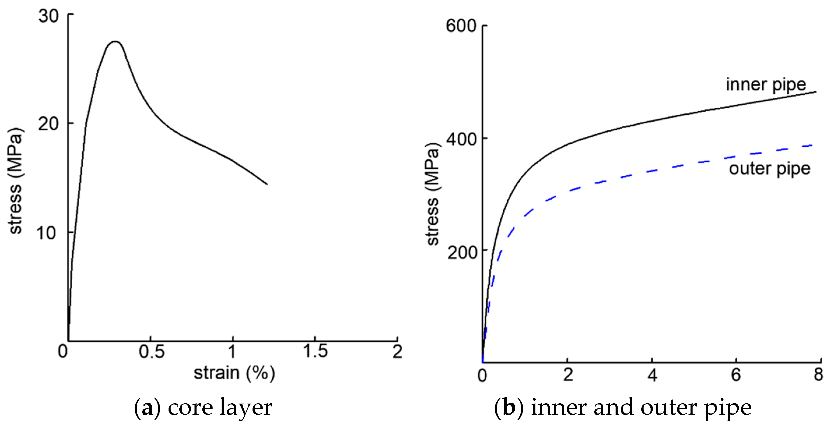
The physical properties of the core layer and pipes are shown in
Figure 1. By measuring the curves in
Figure 1, for the core layer, the yield stress is 27 MPa, Young’s modulus is 9 GPa. In FEA, the perfect elastic-plastic material model is applied for the core layer. For the inner pipe, the yield stress and ultimate stress are 215 MPa and 474 MPa, Young’s modulus is 82.1 GPa. For the outer pipe, the yield stress and ultimate stress are 147 MPa and 381 MPa, Young’s modulus is 59.9 GPa. In FEA, the flexibility-linear hardening model is applied for pipes.
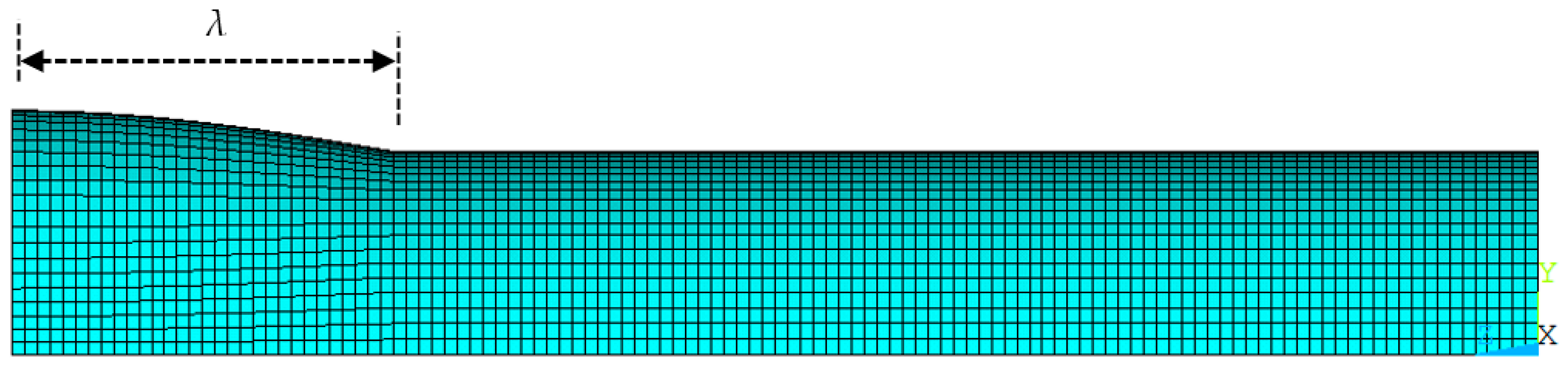
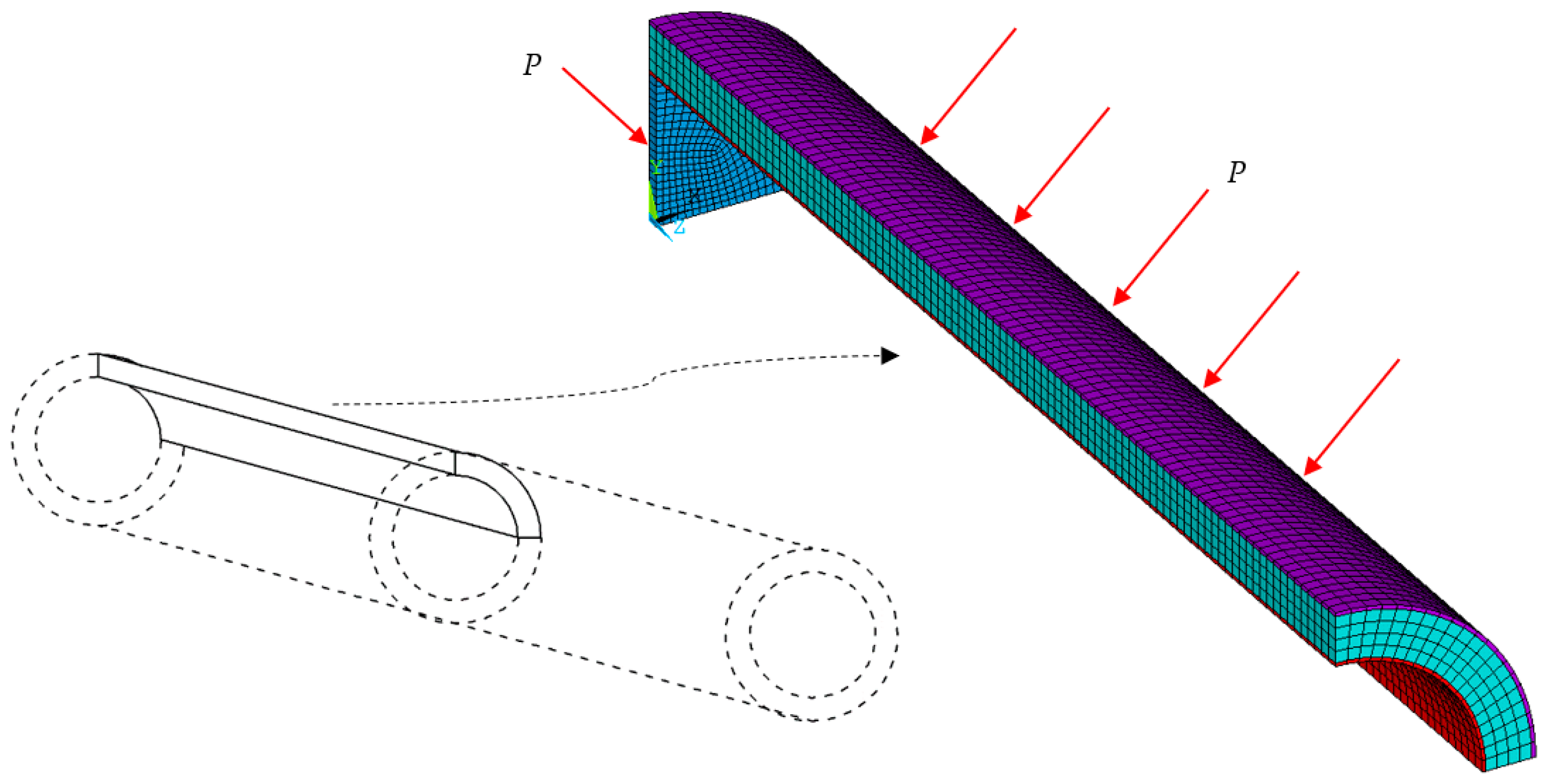
The numerical calculations of this research are performed in ANSYS with an implicit computation procedure. The element type is SOLID185. The finite element mesh and load condition are shown in
Figure 2. The length of the pipe is 1200 mm. Only a quarter of the cross-section of a half-pipe is modelled because of the symmetry. In the circumferential direction, the number of elements is 20, with an element size of about 7 mm on average. In the radius direction, the number of elements is 1, 4, and 1, respectively, for the inner pipe, core layer, and outer pipe. The element size is 5.8 mm for the core layer. In the axial direction, the number of elements is 120, corresponding to an element size of 5 mm. A rigid end is created in the position of
z = 0 to simulate the plug from the experiment. Symmetrical boundary conditions are set in the plane
XOZ and
YOZ.
A fully bonded adhesion condition is adopted between the interfaces of the core layer and metal pipes. In ANSYS, this is realized by coupling the displacement of the nodes from both sides of the interfaces which is the same as that used in Li et al. [
18].
The uniform pressure acts on both the outer surface of the outer pipe and the end of the pipe at the position of z = 0. Thus, the loading condition of this case is the coupling of external pressure and axial compression. Two kinds of load increase simultaneously which is the same as that in the experiment.
At this step, the half-wave number in the circumferential direction is selected to be 2, which will be studied later in
Section 3. The length of the ovality
λ is 50 mm, whose meaning is shown in
Figure 3.
The comparison results between calculations and experiments are shown in
Table 2. Good agreement is confirmed between the collapse strength (
Pe) measured in experiments from [
6] and the collapse strength (
Pco) from FEM calculation in this research.
Then, the mesh sensitivity is performed. As shown in
Table 3, five cases with different element sizes are calculated for every pipe configuration, SP1 SP2, and SP3. The elements of the core layer from each case are almost cubic. The comparison results of the calculation and experiment are shown in
Table 4. Despite the small errors in all five cases, a relatively larger error appears with finer mesh in
Table 4. The reason is that the ovality measured in experiments could not be as perfect as that used in FEM, and the collapse strength is influenced by many factors as shown in the conclusions of this research. From the results, the mesh division of N20 has acceptable accuracy and high computation efficiency.
3. Effect of Ovality Shape in the Circumferential Direction
The circular pipes are usually manufactured by rolling flat plates. During this procedure, ovality in pipe circumferential direction is usually introduced into the pipe, according to the variable,
where
w is the additional variable in the radius direction;
w0 is the maximum amplitude;
nc is the number of half-waves in the circumferential direction;
θ is the central angle.
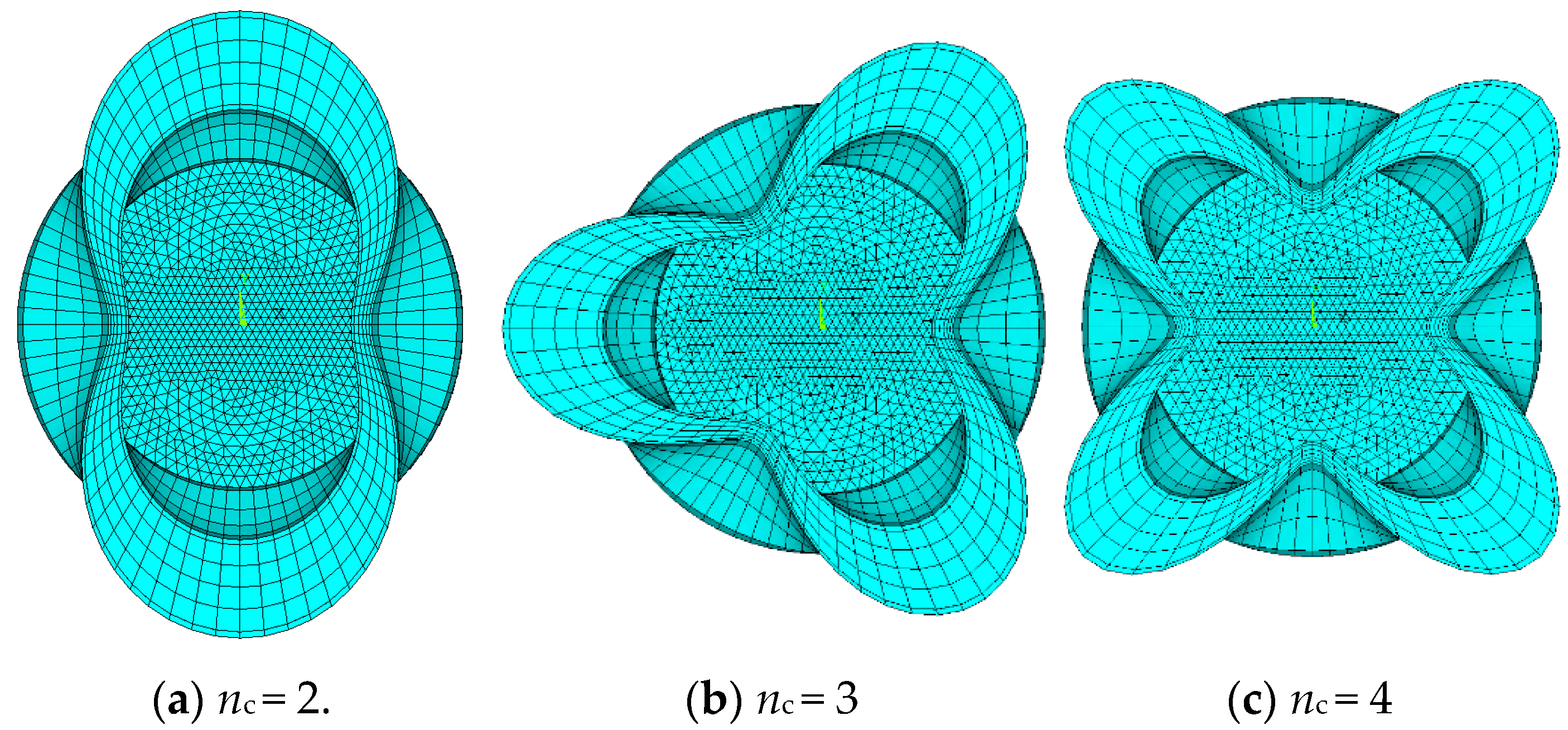
Different types of ovality are compared to each other. For the overall ovality, the value of
nc is selected to be 2, 3, and 4. In this section, half of the whole circle is modelled in each case instead of one quarter in the previous because of the case Nc3. The cross-sections of three patterns are shown in
Figure 4, with a scale factor of 100 for a clear illustration. The comparison result of the collapse pressure of the sandwich pipes is shown in
Table 5.
From
Table 5, the case Nc2 with
nc = 2 is the most severe situation. Therefore, in this paper, the half wave number in the circumferential direction is set to be 2 for the parametrical study.
4. Parametric Study
In the previous calculation, the specimens are under loads of both axial compression and external pressure. The purpose is to compare with the results from the experiment. After the validation, in parametrical study cases, the load is set to be only the uniform external pressure. The length of SPs is 1200 mm, half of the length and one-quarter of the cross-section is modelled. The physical property of the core layer is the same as shown in
Figure 1a. The physical property of the metal pipe is selected as the same as that of the outer pipe in
Figure 1b.
Five groups of pipes with various radii of outer and inner pipes are considered. As shown in
Table 6, the value of
Ro/
Ri is almost evenly distributed between 1.2 and 2.0. In this section, the ovality of the outer and inner pipe is selected to be of the same value, unlike that in [
18], since the effect of ovality is not the principal task in this research.
In each group, four ratios of radius over thickness are set,
R/
t = 20, 25, 40, and 50, for both inner and outer pipe. The value of ovality (
Δ) is set to be 0.01, 0.05, 0.2, and 1%. The length of ovality area (
λ) is 50, 80, 120, 160, 200, 300, 400, 600, and 1200 mm. To perform dimensionless, a ratio of
λ/
Ro is selected, this parameter means the gradient of an ovality in SPs axial direction. In this regard, 240 cases are calculated in each group. The case name is represented by a five-number ‘
abcde’, as shown in
Table 7. In detail, ‘
a’ means the group, ‘
b’ means the ratio of radius and thickness of the outer pipe, ‘
c’ means the ratio of radius and thickness of the inner pipe, ‘
d’ means the ovality length, and ‘
e’ means the ovality.
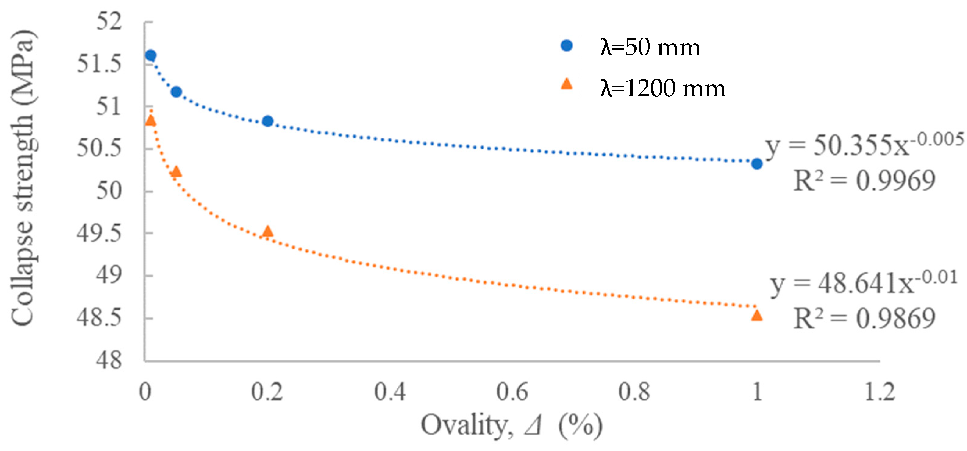
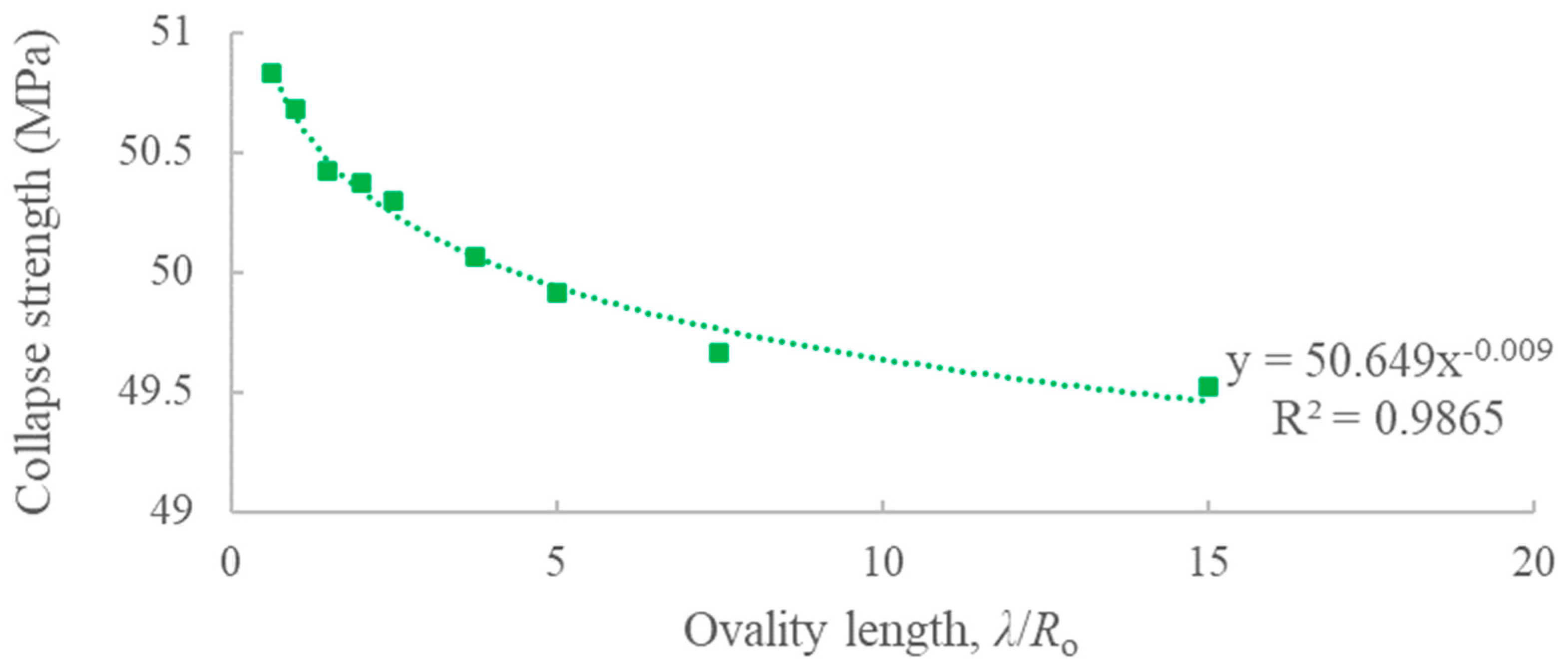
For example, in the case series of ‘313
de’, the relationships between collapse strength (
Pco) and ovality (
Δ) and ovality length (
λ) are shown in
Figure 5 and
Figure 6, respectively.
The relationships between collapse strength and ovality/ovality length follow a power function. The good fit is obtained as illustrated in
Figure 5 and
Figure 6. Moreover, the physical meaning of power function is suitable. When the values of
Δ and
λ are set to be zero, it means no imperfection is introduced to the SPs, so the collapse strength of intact SPs is only decided by the material properties and geometrical parameters. As a result, in the final fitted equation, the power function is selected. Five variables are included, where
Δ and
λ/
Ro describe the features of ovality,
Ro/
to,
Ri/
ti, and
Ro/
Ri describe the collapse strength of intact SPs.
After summarizing all 1200 calculation cases, a fitted equation is derived,
where
,
,
In Equation (3), the expression of fitted collapse strength (Pfit) contains several constants. These constants are regarded as the effect of material properties of SPs.
The accuracy of Equation (3) is checked. Some cases from Group 1 have large errors. In these cases, the value of
λ/
Ro is too large, for example, when
λ = 1200 mm, the value of
λ/
Ro is 20. A large value of
λ/
Ro means the ovality area occurred to a large part of SPs. The issue discussed in this research focuses on the local buckling so that the cases with
λ/
Ro ratios large than 16 are removed. Therefore, 1136 cases are summarized. The comparison result of the other cases between fitted equation and calculation is shown in
Figure 7, in which good agreement is achieved.
In Equation (3), Δ and λ/Ro are the features to describe the ovality. Except for these two parameters, the other two variables, Ro/Ri and R/t, describe the geometrical property of the SP It is concluded that the R/t ratio is a dominant factor not only in the collapse strength of the single-walled pipes but also in the collapse strength of SPs. The influence of the core layer is described by Ro/Ri, a higher value of it means a thicker layer of the core material. There are several constant values included in Equation (3) controlled by the physical properties of SP, since the material has not been changed in this research. The influence of the physical properties is worth to be investigated in the future.
In terms of the geometrical property of SPs, the increase in Ro/Ri and decrease in R/t can both lead to the improvement of the collapse strength of imperfect SPs.
5. Discussion
In Equation (3), the relationship between collapse strength and ovality length and ovality follows a power function. The influence of ratios of radius to thickness (
R/
t) of inner and outer pipe refers to Equation (2) in [
18]. It is confirmed that the influence of the
R/
t of the inner pipe is greater than that of the outer pipe.
The value of md in Equation (3) is almost twice of nl when the ratio of Ro/Ri is set, that means for a certain SP, the effect of ovality is a more dominant factor of ovality to reduce the loading capacity when the SP is acted by external pressure.
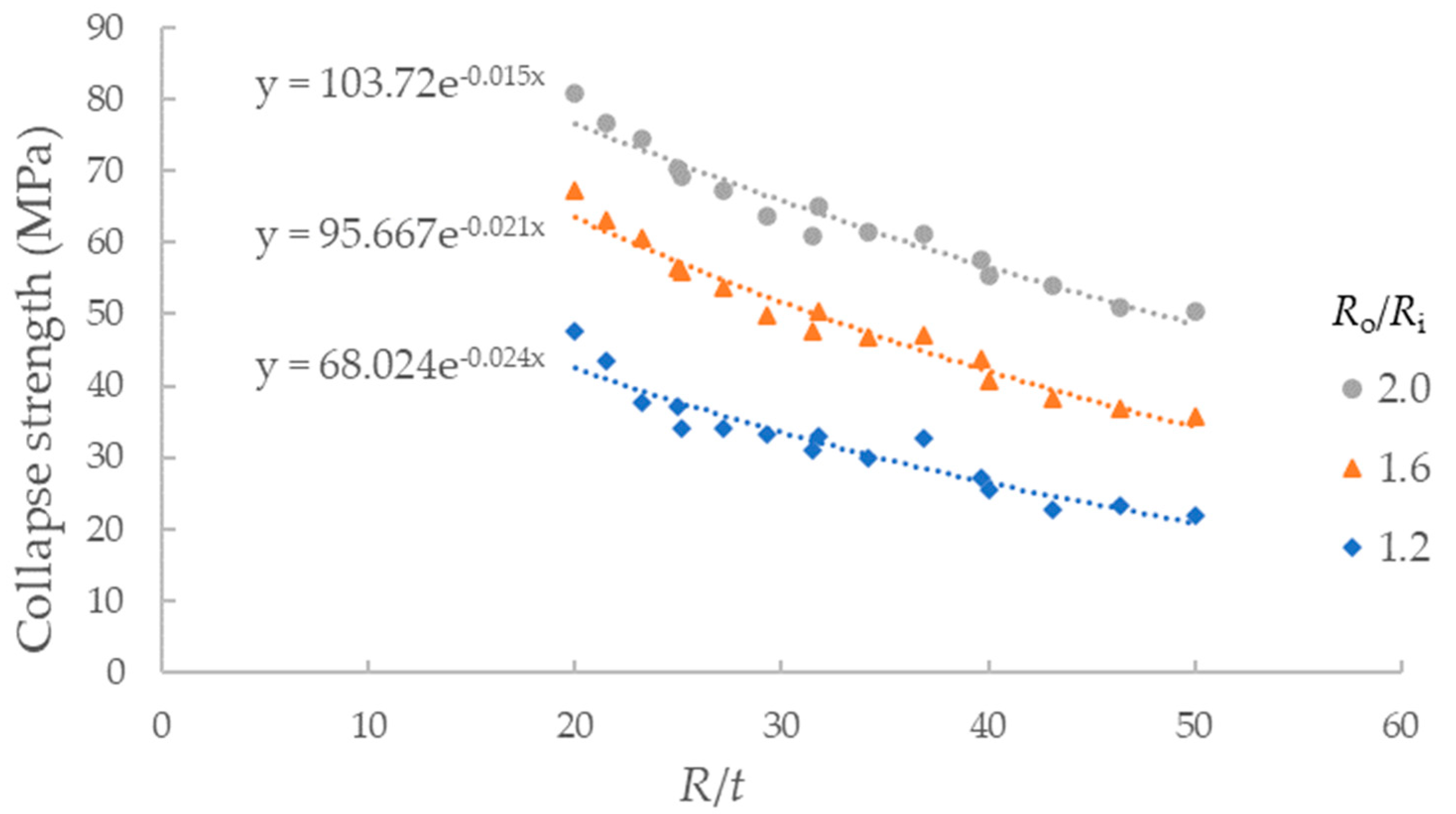
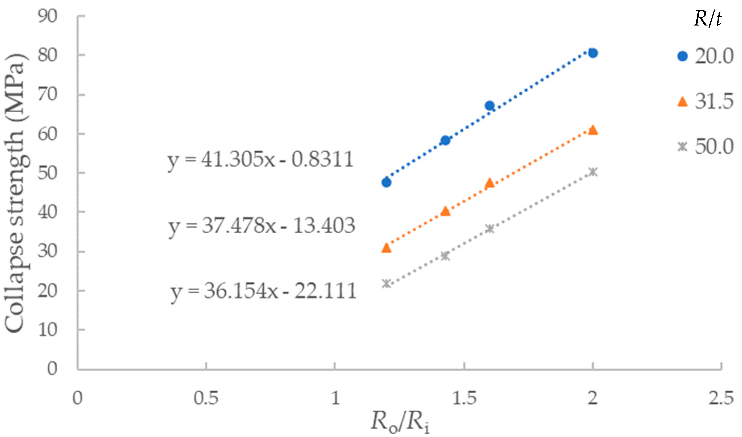
The relationship between collapse strength of imperfect SPs and
R/
t is shown in
Figure 8, and the relationship between collapse strength and
Ro/
Ri is shown in
Figure 9. In both figures, the ovality is the same with the parameter
λ/
Ro = 2.0 and
Δ = 0.2%. It is clear that the collapse strength is greater of SPs with a higher value of
Ro/
Ri or a lower value of
R/
t. The changing rates of the curves are almost the same in both figures. However, it is concluded from the expression of
C in Equation (3) that the influence of
R/
t is greater than that of
Ro/
Ri by checking the partial derivatives of both parameters. Due to the material strength of the metal pipe that is much higher than that of the core layer, the improvement of strength of both outer and inner pipes results in significant promotion of the collapse strength of SPs. Thus, in order to obtain SPs with a higher carrying capacity of external pressure, it is recommended to increase the strength of metal pipes, especially the inner pipe.
Considering local buckling as the main concern, 64 cases with the ratio of λ/Ro greater than 16 are taken out of consideration. From the comparison result of calculation and Equation (3), the error of most cases is smaller than 20%, except for 51 cases out of 1136. The average value of error is only 4.4%, which indicates a good fit.


