Article

Study on the Performance of an Electric-Field-Enhanced Oil–Water Separator in Treating Heavy Oil with High Water Cut

1
Beijing Institute of Petrochemical Technology, Beijing 102617, China
2
Beijing Key Laboratory of Pipeline Critical Technology and Equipment for Deepwater Oil & Gas Development, Beijing 102617, China
3
State Key Laboratory of Offshore Oil Exploitation, Beijing 100028, China
4
CNOOC Research Institute Co., Ltd., Beijing 100028, China
*
Author to whom correspondence should be addressed.
J. Mar. Sci. Eng. 2022, 10(10), 1516; https://doi.org/10.3390/jmse10101516
Submission received: 3 September 2022 / Revised: 3 October 2022 / Accepted: 12 October 2022 / Published: 17 October 2022

Abstract

:
As most offshore oilfields come to the middle- and late-exploitation period, and with the popularization of tertiary enhanced oil recovery (EOR) technology, the physical properties of produced fluids become more complex, bringing new challenges to oil-water separation. Conventional solutions, such as increasing the input of chemicals, enlarging the volume of the separator equipment, and extending the processing, are usually uneconomical and space-wasting. Electric-field-enhanced oil-water separation equipment was developed in this paper, and a mine field test was carried out. With the average water cut of different sampling ports and the overall dehydration rate taken as indicators, the effects of electric field frequency, inlet flow, chemical type, and addition upon the separation of the device were evaluated. The experimental results showed that for the ABJ mixed liquid, the optimal operating frequency of the electric field is above 3500 Hz. Compared with traditional separation equipment, the advantages of the electric-field-enhanced oil–water separation equipment are more significant in large flow conditions. When the water cut of the platform inlet fluctuates between 78% and 97%, and without the addition of chemicals, the average water cut was reduced to 7% and the average dehydration rate reached 90%, an improvement of about 15%.

1. Introduction

Crude oil usually exists in the form of oil–water emulsion, and effective demulsification is the key to ensuring the subsequent production and processing of the oilfield in an orderly manner [1]. In engineering practice, the two-stage series process of “three-phase separator followed by electric dehydrator“ is often used to ensure that crude oil meets the specified quality standard. However, when the water cut of the crude oil is over 90%, this process is usually time-consuming and labor-intensive [2,3]. At the same time, compared with onshore platforms, which are affected by the development environment and space limitations, the development process for offshore platforms often requires higher performance and various parameters of oil–water separation equipment [4,5]. For this reason, many scholars have tried to combine processes such as electrostatic demulsification, centrifugation, microwave radiation, and other technologies with three-phase separation devices to simplify the operation process, improve the processing efficiency, eliminate the negative impact of chemicals on the environment, and realize harmony in economic returns and environmental protection [6,7,8,9].
In recent years, the synergy of “integration of electric and gravitational fields” has attracted much attention in the industry. Vessel internal electrostatic coalescer (VIEC) technology was first developed by the ABB company in 1999 and was successfully applied to the Troll C platform of Norsk Hydro in 2003, showing good performance [10].
Electrostatic coalescer separation performance is affected by many factors. In 2001, Lee et al. conducted a study on the effect of the electric field type on coalescer efficiency. Their results, contrary to the results of most investigators, indicated that AC fields were more effective than pulsed DC fields in increasing the coalescence rate [11]. In 2005, Wood et al. studied the influence of the VIEC components on the multiphase flow inside the separator by establishing a computational fluid dynamics (CFD) model; the backflow phenomenon in the separator was captured, and the fluid flow was similar to the experimental results [12]. In 2007, Fortuny et al. and Fjeldly et al. studied the effects of a series of crude oil emulsions and their variables, including pH, salt contents, and water contents, on the demulsification process; they found that higher demulsification efficiency contained higher water cut, unless both high pH and salt content were involved [13,14].
Simone et al. experimentally studied the relationship between the performance of an electrostatic coalescer and the water cut and droplet size distribution of an emulsion, as well as the effect of chemicals. The results showed that the separation of the water phase and the emulsion can be significantly promoted by the application of an AC electric field [15]. In 2015 and 2016, Aryafard et al. and Kakhki et al. established mathematical models to simulate the influence of the parameters of the electric field on the dehydration efficiency. Their results showed that the electric field has a significant effect on dehydration efficiency, and that increasing the current frequency can enhance the electric field strength and reduce the water cut of crude oil after treatment [16,17].
Kothmire et al. reported an experimental study of two different modes of operation, using COMSOL to calculate the volume of the emulsion under an electric field of ~0.3 kV/cm to 1.0 kV/cm; they found a good correlation with water separation [18]. Mhatre and Thaokar experimentally investigated the spatial electric field distribution and electrode configuration in an electrocoagulator, showing that they played an important role in effective coalescence [19,20]. In 2020, Ismail et al., using a self-developed compact high-performance electrostatic coalescer, placed several static mixers with different geometries in a compact inline coalescing chamber to test the demulsification performance of crude oil in Arabian media, under different temperatures and electric field strength conditions; their results showed that the addition of static mixers in the electrostatic coalescing tank generates favorable mild turbulence, which enhances the dewatering performance [21].
Most of the studies on VIEC technologies have been laboratory experiments and simulations. There is a relative lack of systematic studies on heavy oil treatment in the industry, involving electric field parameters, flow rates, and chemical effects on VIEC separation performance. Therefore, this article reports on a recent study conducted by our research group, the CNOOC Research Institute, and others to self-develop a 10 m3/h electric-field-enhanced oil–water separation device and to carry out a systematic dynamic test on the SZ36-1CEPK platform in the Suizhong oilfield. The dehydration effect under the different of electric field parameters, the inlet flow, and the types and amounts of chemicals were comprehensively investigated, to provide an empirical basis for the development and industrial application of efficient and compact electrical dehydration equipment in offshore oilfields.

2. The Oil–Water Separator Design

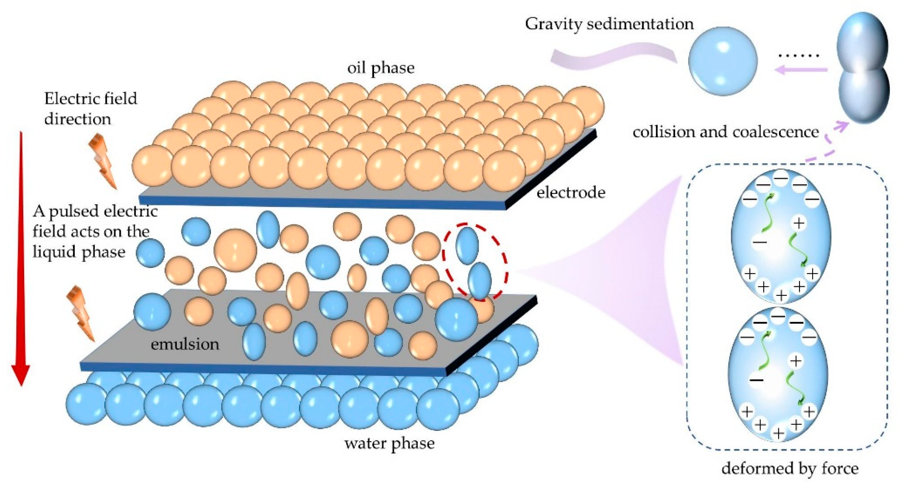
2.1. Coalescer and Settlement Performance Theory

The three-phase separator mainly relies on the gravity of the water particles to complete oil–water separation [22]. Ignoring the flow of liquid, the droplets in the tank are affected by the viscous resistance, the buoyancy, and the gravity, and when their resultant force is 0, the droplet settling velocity is greatest [23]. That is:
π D 2 4 C x ρ o v 2 2 + 4 3 π ( D 2 ) 3 ρ o g = 4 3 π ( D 2 ) 3 ρ w g
v = D 2 ( ρ w ρ o ) g 18 μ o
where D is the droplet diameter, m; Cx is the oil resistance coefficient, Nm/s; ρo and ρw are the densities of oil and water, respectively, in kg/m3; v is the sedimentation velocity, m/s; g is the acceleration of gravity, m/s2; and μo is the continuous oil phase viscosity, Pa·s.
It is clear that the settling velocity of the droplets is positively related to the square of the droplet size, which demonstrates that the performance is highly improved, possibly by the increased droplet size [24].
The electrostatic coalescence module was added to the separator tank, primarily to use the influence of the electrostatic field on the conductive water droplets in an insulating oil media. When the droplets passed through the rectangular channel of the VIEC module, they were subjected to electric field force. According to the studies of Song et al. on the numerical simulation of droplets, the electric field force on the droplets can be expressed, using the Maxwell stress tensor [25], as follows:
F e = ( ε 0 ε r E E ) 1 2 E 2 ε 0 ε r + ( 1 2 ρ w ε 0 ε r ρ w E 2 )
where ε0 is the vacuum permittivity, F/m; εr is the relative permittivity, without dimensions; and E is the intensity of the electric field, V/m. The first term on the right in the formula is the electric field force of the charge to the surface charge in the direction of the electric field; the second term is the polarization stress of the electric field force; and the third is the force caused by the change in medium density. This means that the water molecules in the oil are polarized as dipoles, with a positive and a negative end; a dipole force was generated between neighboring droplets, pressing them together. The tension of the surface induces the emulsified membrane between them to flow and, eventually, to drain. This improves the coalescence to large droplets [26]. A diagram of this process is shown in Figure 1.
A model was assumed, as shown in Figure 2. According to the dynamic analysis of droplets by Zhang et al. [27,28,29], the above dipole force between droplets can be expressed as follows:
F e = F r a d + F t a n
where Frad and Ftan are, respectively, the radial force that drives the droplets to deform and the tangential force that makes the line connecting the centers of the two droplets tend to the direction of the electric field. They satisfy the following equation:
F r a d = 3 π φ 2 ε O E 2 D 1 3 D 2 3 16 d 4 ( 3 K 1 cos 2 θ 1 )
F t a n = 3 π φ 2 ε O E 2 D 1 3 D 2 2 8 d 4 K 2 s i n 2 θ
where d indicates the distance between the centers of the two droplets, m, and θ is the angle between the electric field line and the center connection of the two droplets. The Clausius–Mossotti (φ) and the constant coefficient s(K1), (K2) are expressed as follows:
φ = ε w ε o ε w + 2 ε o
K 1 = 1 + 8 2 φ D 1 3 d 5 2 ( 4 d 2 D 2 2 ) 4 + 8 2 φ D 2 3 d 5 2 ( 4 d 2 D 1 2 ) 4 + 3 φ 2 D 1 3 D 2 3 ( 12 d 2 D 1 2 D 2 2 ) 256 ( d 2 R 1 2 R 2 2 ) 4
K 2 = 1 + 4 3 φ D 1 3 d 3 8 ( 4 d 2 D 2 2 ) 3 + 4 3 φ D 2 3 d 3 8 ( d 2 D 1 2 ) 3 + 4 3 3 φ 2 D 1 3 D 2 2 32 ( 4 d 2 D 1 2 D 2 2 ) 3
It may be noticed that the dipole force is inversely proportional to the fourth power of the distance between the droplets, which means that the dipole force decreases rapidly as the distance between the droplets increases. However, when the water cut of the oil is high, the droplet density is sufficiently large, and there will be many of these close contacts, which are good ways of increasing droplet size.

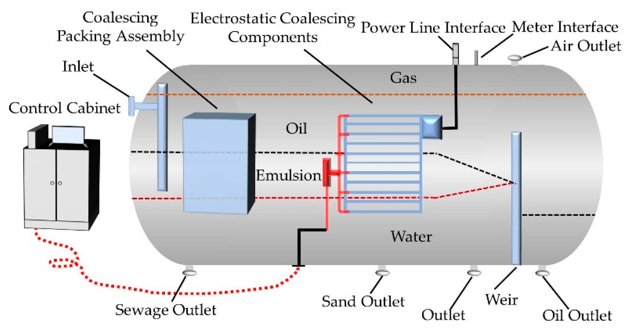
2.2. The Oil–Water Separator Structure

The internal overall layout of the electric-field-enhanced oil–water separation device is shown in Figure 3. The produced liquid from the wells is fed into hydrocyclones for preliminary separation of the gas and liquid. The gas released is discharged through the gas outlet and collected for use. The liquid enters the horizontal separator after passing through the bottom devortexer. The oil in the liquid floats up through the coalescing packing assembly to form an oil phase, and after dehydration in the rectangular channel of the VIEC, it overflows the weir plate and flows out of the oil outlet at the bottom of the tank. The basic parameters of the internal components of the oil–water separation device were designed on the basis of the process data of the pilot test platform shown in Table 1, including the size and installation parameters of the coalescing packing assembly and the electrostatic coalescence module. It should be noted that only a reference value is provided here.

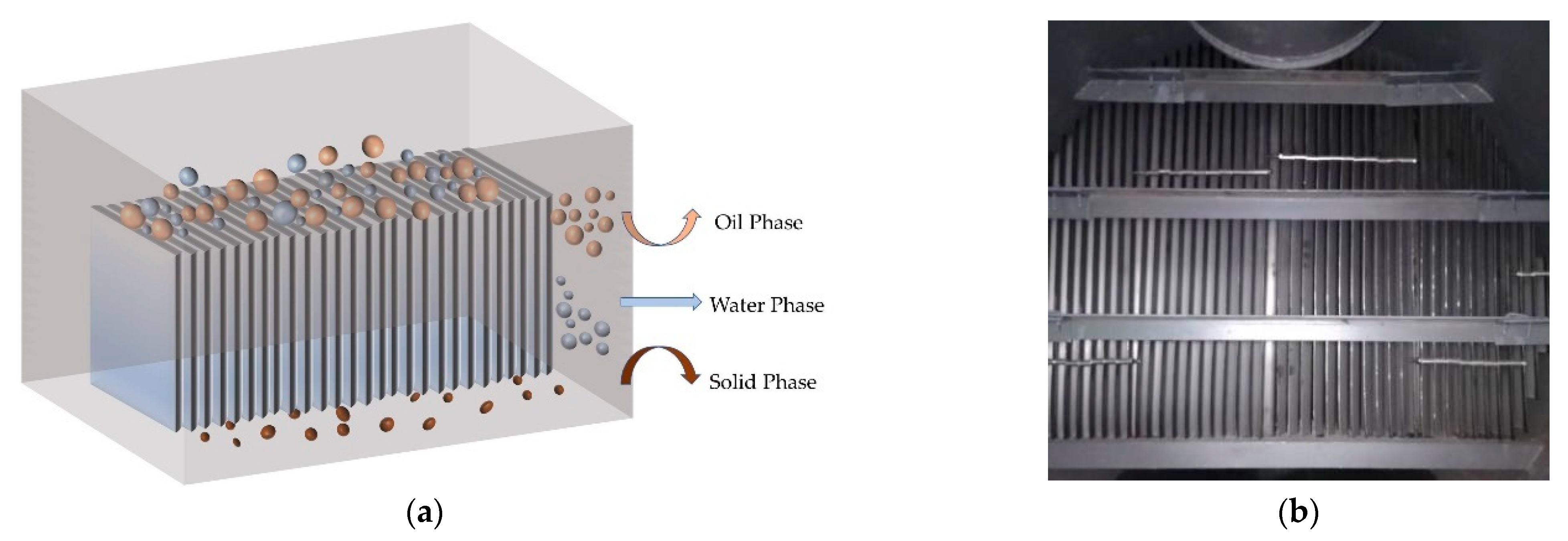
2.2.1. Parameter Design of the Coalescing Packing Assembly

The calculation of basic parameters of the oil–water separator, according to the process parameters shown in Table 1, mainly considers the distance and time of the particle sedimentation [30]. The analytical model is shown in Figure 4. The coalescing packing assembly was mainly used to accelerate the floating of oil particles to form an oil phase. It was composed of multiple pieces of lipophilic and hydrophobic stainless-steel-inclined plates with a size of 0.3 m (length) × 1 m (width) × 0.02 m (height) and a thickness of 5 × 10⁻⁴ m. The liquid flowed in a “Z” shape in the channel of the inclined plate group, and the flow direction and section were constantly changing, which provided the adhesion and coalescence of the oil droplets on the surface of the corrugated plate and more opportunities for the collision between the oil droplets [31]. The coalesced droplets were detached from the surface of the inclined plate under the action of water flow’s shear stress, thereby improving the oil–water separation efficiency. The model and the physical diagram are shown in Figure 5a,b. In an ideal state, the first-stage coalescing packing assembly inside a conventional three-phase separator can usually remove water particles with a particle size d > 1.5 × 10−40 m, and shorten the settling time with a particle size d > 1 × 10⁻⁴ m.
In the laminar flow state, the droplet settling velocity (v) satisfied Equation (2). Therefore, the settling velocity of droplets with particle size 1.5 × 10⁻⁴ m and 1×10⁻⁴ m were 1.47 × 10⁻⁴ m/s and 6.52 × 10⁻⁵ m/s, respectively. The time required for settling and the length of the tank corresponding to the settling time were calculated according to t = D X v and L = t t d × L d . They were t1.5 = 2.27 min, t1 = 5.12 min, L1.5 = 0.39 m, and L1 = 0.89 m, respectively. Where, the numbers in all subscripts of the article represent the particle size of the particles; Dx is the distance between the inclined plates, m; td is the hydraulic retention time, 30 min; and Ld is the length of the tank, m.
According to the calculation results, when the distance between the inclined plates was 0.02 m, the length of the corresponding assembly required, when the dispersed phase droplets with a particle size larger than 1.5 × 10⁻⁴ m were completely removed by the coalescing packing assembly, was 0.39 m, rounded to 0.4 m (i.e., Lc in Figure 3). The water droplets with smaller particle sizes can be separated, the axial length of the assembly can be increased, or the spacing between the inclined plates can be reduced.

2.2.2. Parameter Design of the VIEC Components

The VIEC components were designed as a perforated plate wall and installed at the supporting wall, perpendicular to the fluid flow inside the three-phase separator, a position that allowed most of the emulsion and oil to pass through without adding to the platform layout [32,33]. The VIEC mainly included three parts:
  • The electrode assembly inside the three-phase separator;
  • The connector assembly through the separator wall; and
  • The power and its control devices that were located in the nearby control room.
In order to be able to use this technology in the case of high water cut, each electrostatic coalescence module was required to work normally under the coexistence of oil, gas, and water, without a “collapsed electric field” [34]. Therefore, the single rectangular channel of the traditional electrostatic coalescence module was primarily designed as double-insulated electrodes. However, this caused the effective electric field strength to be attenuated. In this paper, the method of an alternately installed metal electrode plate and an insulating electrode plate was adopted [35]. The size of the VIEC body was 0.44 m (length) × 0.44 m (width) × 0.15 m (height), and it was composed of a metal pole plate, an insulated metal pole plate, and plate brackets. Two kinds of electrodes were installed alternately and vertically to form a wide rectangular flow channel, which avoided the problem of oily-sludge-deposition blockage and was conducive to the long-term stable operation of the equipment.
The insulation process of the insulated electrode plate was mainly via surface insulation treatment on the electrode plate, the transformer, and the low-voltage introduction device, with whole vacuum casting using epoxy resin casting technology. The input terminal of the built-in transformer was connected to the external high-frequency pulse power supply. The output high-voltage terminal was connected to the metal pole, while the other was grounded together with the external flange interface, the insulating pole, the bracket, and the tank body of the three-phase separator. This design avoided the short circuit when high voltage was connected [36]. Figure 6 shows a schematic diagram of the built-in electrode assembly and the actual appearance of the electrodes that were installed.
The electrostatic coalescence module was controlled by the PC in the control room, and the communication between them was presented through an RS485 communication protocol. In addition to adjusting the power parameters, the module also monitored, in real time, the running status of the VIEC. Usually, the VIEC components were started or stopped by the master switch; however, because each pair of electrode plates was provided with an independent switch, each electrode plate could also be monitored and controlled independently.
In addition to considering the parameters shown in Table 1, the following two aspects in the design of the installation location of the VIEC components were considered:
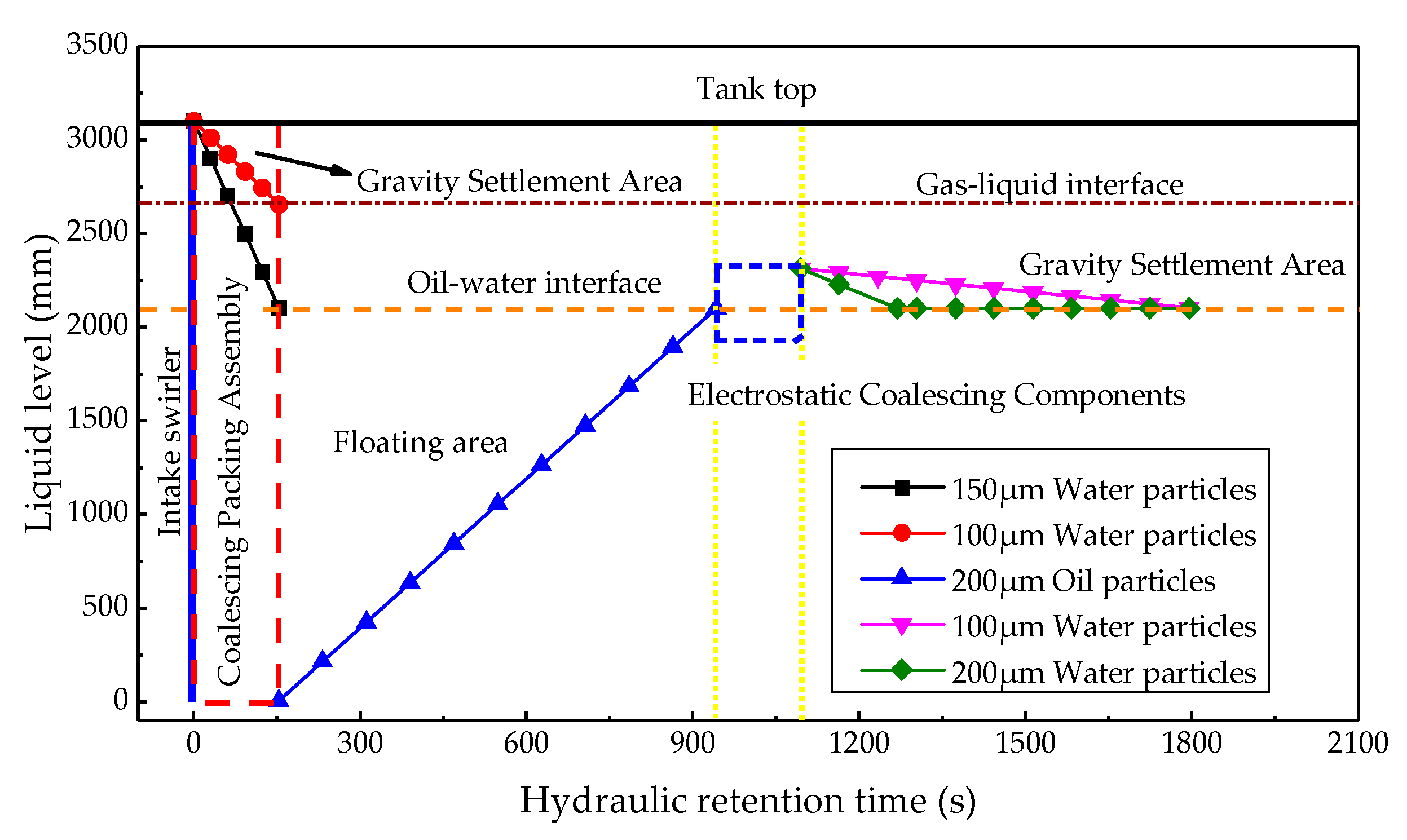
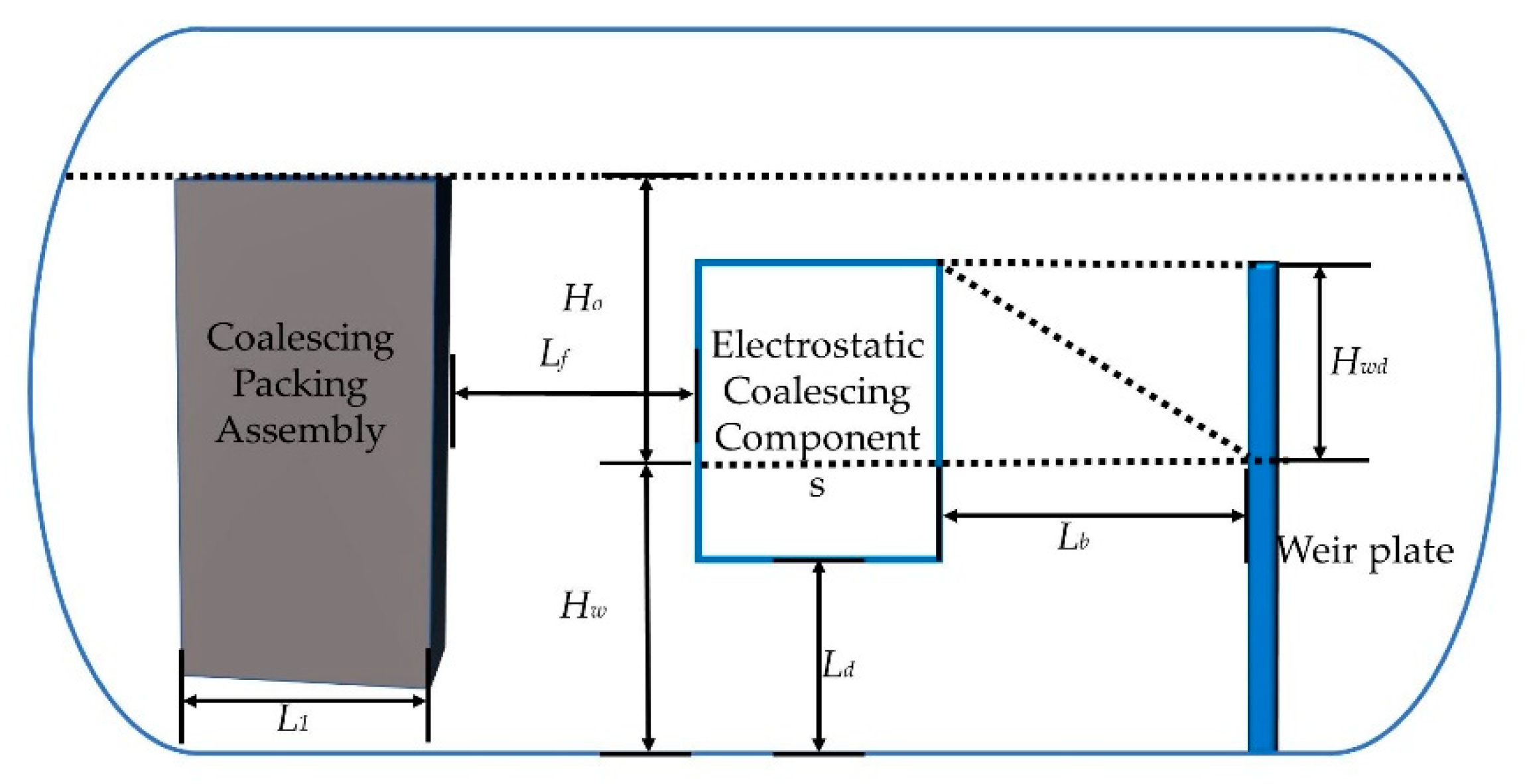
  • The space in front of the VIEC components ensured that the oil particles at the bottom of the tank could float to the oil phase, and the height of oil–water interface (Hw) had to be higher than the bottom of the VIEC to ensure that all the oil could enter the flow channel;
  • The space downstream of the VIEC components ensured that the water particles of after coalescing under the electric field force had enough time to settle. In order to strictly ensure the safety performance of the device, its top had to be at least 0.2 m below the gas–liquid interface [37].
Assuming that an oil particle with a particle size of 2 × 10⁻⁴ m is only affected by gravity during the process of floating to the oil–water interface, the floating velocity v2 = 3.01 × 10⁻³ m/s and the floating time (t2) (i.e., the residence time at the space in front of the VIEC) could be calculated according to the following equation:
t 2 = H w v 2 = 11.63 min
where the height of the oil–water interface was Hw = 2.1 m. From the equation L 2 = t 2 t d × L d , the distance between the front end of the electrostatic coalescing components and the downstream of the coalescing packing assembly were calculated as 2.02 m (i.e., Lf in Figure 3).
After being accelerated by the coalescing packing assembly, the floating velocity of the oil particles increased, so it was reasonable to believe that those oil droplets with a particle size of <2 × 10⁻⁴ m could also float to the desired height.
The three-phase separator was usually able to remove particles of approximately 1 × 10⁻⁴ m, and we used this as a design criterion. Here, we mainly considered the velocity and the time of the water particles with a particle size of 1 × 10⁻⁴ m and 2 × 10⁻⁴ m that underwent gravity sedimentation after passing through the electrostatic coalescence component. According to Equation (2), vwd1 = 6.52 × 10⁻⁵ m/s, vwd2 = 2.61 × 10⁻⁴ m/s. The settlement time was further calculated as follows:
t w d = t d t 1 t 2 t Δ
where the wd in the subscript represents particle sedimentation and the number still represents the particle size; the time required for the droplet to pass through the electrostatic coalescing component was calculated as tΔ =2.54 min. Therefore, the corresponding settlement time was twd = 10.71 min, and the settlement heights were Hwd1 = 0.04 m and Hwd2 = 0.17 m, respectively.
The distances (Lb) between the downstream of the electrostatic coalescing components and the weir plate were calculated as 1.86 m, according to the following equation:
L b = t w d t d × L
In order to ensure that the water particles with a particle size of 1 × 10⁻⁴ m at the top of the electrostatic coalescence components completed sedimentation within the sedimentation time, the upper reference installation height of the VIEC was less than 2.14 m.
All of the parameters of the VIEC components were considered. According to this analysis, with the hydraulic retention time as the horizontal axis and the liquid level as the vertical axis, the schematic diagram of the droplet sedimentation and the floating curve inside the separator is shown in Figure 7.

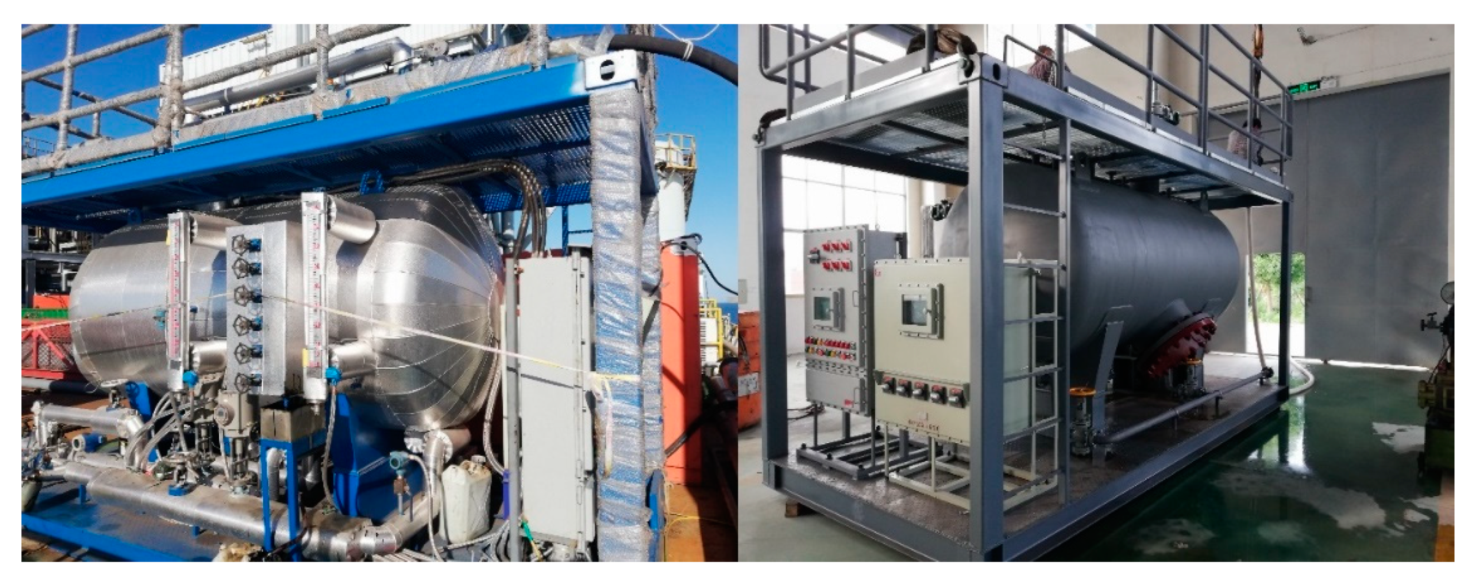
3. Experimental Set-Up and Process

3.1. Experimental Set-Up

The test prototype used in this paper mainly included an electric field-enhanced oil–water separator skid, an instrument control system, and a high-frequency pulse power supply, as shown in Figure 8.
The electric-field-enhanced oil–water separation skid was a separation tank with a built-in VIEC component. Its design size was 5.2 m (length) × 2.4 m (width) × 3.695 m (height), the design flow was 10 m3/h, the volume was 8.7 m3, the design pressure was 1.6 MPa, and the design temperature was 150 °C. The inlet was set at the upper left of the tank and the water and oil outlets were on both sides of the weir plate at the bottom of the tank. Multiple sampling ports were set at the inlet of the separator, at the outlet of the oil phase, and between the VIEC components and the weir plate. In order to assist in regulating the internal liquid level of the separator, safety valves, flow meters, liquid level gauges, pumps and other related instruments were also set up.
To better adapt to the changes in the physical properties of the crude oil, the power supply adopted the self-developed high-frequency/high-voltage AC pulse with the function of increasing the voltage in stages within pulse width, which greatly eliminated the adverse effects of spikes on the system under high-frequency/high-voltage working conditions, and had high operating stability. This was also a key to the efficient operation of the electric-field-enhanced oil–water separator [38]. After the power supply was boosted by the transformer, the AC pulse output was realized, with a frequency of ~500 Hz to 20 kHz, a voltage of ~100 V to 20 kV, and a duty ratio of ~5% to 49%, which could be adjusted on demand.

3.2. Process

The test was conducted on an eight-leg center platform, 36-1CEPK, in Suizhong, where the three-phase separator is the main equipment for crude oil dewatering. A total of three separators are installed there, of which, two are in the first stage and one in the second stage. For a better comparison, the original plan was to run the test device in parallel with the second three-phase separator to carry out secondary treatment on the liquid after the first stage separation treatment. However, due to the layout of the main platform, the distance of the first stage three-phase separator outlet pipeline is far away from the pilot plant. After the comprehensive trade-off, the test material was replaced by the original integrated liquid mixed, with chemicals to an ABJ mixed liquid without added chemicals. (That is, the mixture containing oil, water, and gas from platforms A, B, and J was directly exported by a pipeline to the pilot plant for the test). This obviously increased the difficulty for the pilot plant.
The specific gravity of the crude oil in the ABJ mixed liquid, which was high water cut heavy oil, was ~0.96 to 0.97; the water cut was ~78% to 97%; and the temperature was 75 °C,. During the test, the influence of electric field frequency, inlet flow, types of chemicals, and addition, etc., on the performance of the electric-field-enhanced oil–water separator when applied to heavy oil with a high water cut was investigated, and the optimal operating parameters were determined. When the VIEC was without power, the electric-field-enhanced oil–water separation device was equivalent to the three-phase separator of ordinary engineering. Therefore, the validity was verified by the VIEC with or without power supply test [39]. After the start-up procedure, the operators adjusted parameters and initiated a test run. After a stabilization period of 2 h, data logging was started, and each parameter was logged twice, with an interval of 1 h each time. The water cut of each sample was measured using a rapid analysis instrument, the petroleum water content analyzer, to analyze the performance of the VIEC components and the integrated system.

4. Results and Discussion

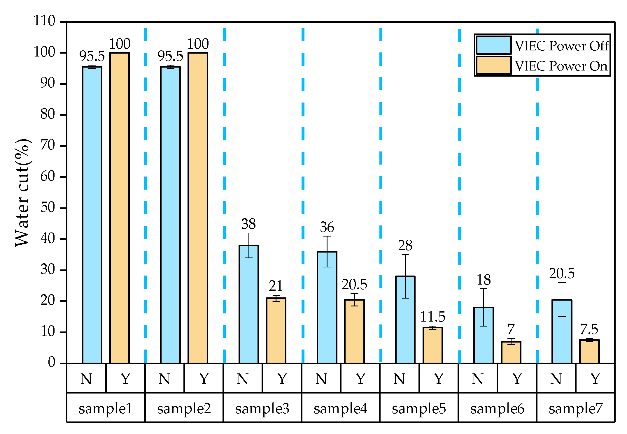
4.1. Influence of the Electric Field Frequency

Several tests were performed to determine the optimal operating frequency. The frequency setting was gradually increased from 1500 Hz to 3500 Hz, the increment was 500 Hz, the voltage and the duty cycle were separately kept at 250 V and 8%, respectively, and the output was 4.98 kV through the high-frequency transformer.
The ABJ mixed liquid (i.e., the water cuts in the inlet) and the water cuts in the oil outlet were sampled and tested. Figure 9 shows the effect of different frequencies on the performance of the electric-field-enhanced oil–water separator in treating heavy oil with high water cut when the flow was 6.5 m3/h, the pressure was ~170 kPa to 210 kPa, the hydraulic retention time was 30 min, and the water and oil level of the oil–water cavity were ~700 mm to 750 mm and ~450 mm to 600 mm, respectively. We know that high temperature decreases the viscosity of crude oil and increases the chance of water droplet collision, which is conducive to the rapid separation of oil and water; however, too-high temperatures are bound to consume fuel, resulting in higher heat cost. Considering the dehydration efficiency and economic benefits, the operating temperature was set to ~55 °C to 65 °C. As can be seen from Figure 8, when the frequency was 1500 Hz, the water cut in the oil outlet was 25%, which was basically the same as that at 2000 Hz. However, the color of the drained water was black when the frequency was 1500 Hz; analysis indicated that the oil cut in the water outlet was too high and did not meet the requirements. Therefore, the VIEC had no significant electrocoalescence effect on the stabilized emulsion at 1500 Hz. When the frequency increased from 2000 Hz to 3500 Hz, the water cut in the oil outlet gradually decreased from 25% to approximately 12%. When the pulse frequency was 3000 Hz, the dewatering rate showed a significant increase. The water cut of the oil outlet was the lowest at 3500 Hz. This was because when the frequency of the external field changed, the vibration amplitude of the water particles also changed [40]. The electric field frequency of 3500 HZ is close to the natural frequency of water particles in the crude oil water-in-oil emulsion system, the vibration frequency of water particles to reach the maximum, the most absorbed electric field energy, the strongest polarization effect, the largest polarization force, and the lowest oil–water interface film strength. Adjacent water particles in the electric field force accelerated collision agglomeration, the water particles’ sizes were increased, and the gravitational sedimentation was accelerated. With a continued increase in the electric field frequency, the positive and negative alternating period of the electric field was shorter than the minimum oscillation period required of the water particles and the oscillation process of water particles could not be synchronized with the alternating process of the electric field; i.e., the polarity of the electric field changed before the water particles completed an oscillation cycle, thereby generating an electrostatic force opposite to the oscillation or tensile direction, and the electrostatic field could not continue to provide the driving force of the oscillation deformation of the droplet and canceled out the inertia force of the droplet to continue to deform [41]. Therefore, we believe that for the ABJ mixed liquid, a voltage of 250 V, a pulse frequency of 3500 Hz, and a duty cycle of 8% were relatively good operating parameters of the electric-field-enhanced oil–water separator.

4.2. The Influence of Flow on the Dehydration Effect

The VIEC components were all powered on during the test of the effect of frequency on the dehydration effect; to verify the effectiveness of the electric-field-enhanced oil–water separator, we conducted a test under the same flow and without powering the VIEC components. The results are shown in Table 2. It can be seen that in the case of small flow (that is, 6.5 m3/h), the dewatering advantage of the electric-field-enhanced oil–water separation device was not obvious, which caused us to doubt the effectiveness of the device. Therefore, we increased the flow rate to 10 m3/h, and tests of the VIEC components, power-off and power-on, were carried out. During this period, the electric field parameters in the case of power-on of the VIEC components were set as the optimal parameters considered above. Because the produced fluid from the platform was discontinuous and the liquid inside the separator was left standing for a long time, it was not accurate to measure the dehydration performance of the device only by comparing the water cut of the oil outlet. Therefore, six additional sampling ports were added for auxiliary analysis.
In the large flow, the average water cuts of each sampling port, with and without power of the VIEC, are shown in Figure 10. In the figure, N and Y represent the water cut of VIEC, power-off and power-on, respectively. All data were taken as the average value of the water cut of the tested samples. The sampling port 7 was located at the oil outlet. The sampling point 6 was located at the inlet of the oil chamber; the average water cut was 20.5% with large flow and VIEC power-off and 7.5% with VIEC power-on, which was significantly lower. The sample point 5 was located at the oil phase; the average water cut was 28% with large flow and VIEC power-off and 11.5% with VIEC power-on, which was also significantly lower. The sampling ports 3 and 4 were located at the emulsion layer; it can be seen that the average water cut of this area under VIEC power-on was lower, 15%, than that with power-off. The sampling ports 1 and 2 were located at the water phase; the average oil cut of this area when the VIEC was power-off was more than 4% higher than when the power was on. Comprehensive analysis showed that the dehydration rate of the VIEC with power was approximately 15% higher than that without power at large flow. Therefore, the electric-field-enhanced oil–water separation device had a stronger dewatering capacity than the traditional three-phase separation device under the large flow. The dewatering advantage was more pronounced relative to that at a smaller flow. This was expected, because the flow directly affects the residence time of water droplets in the electric field [42]. Obviously, as the flow rate increased, the residence time decreased, which resulted in many small droplets not having enough time to coalesce, or not coalesce sufficiently under the electric field. Therefore, it was reasonable to conclude that an electric-field-enhanced oil–water separation device can significantly shorten the hydraulic residence time and reduce production cost.

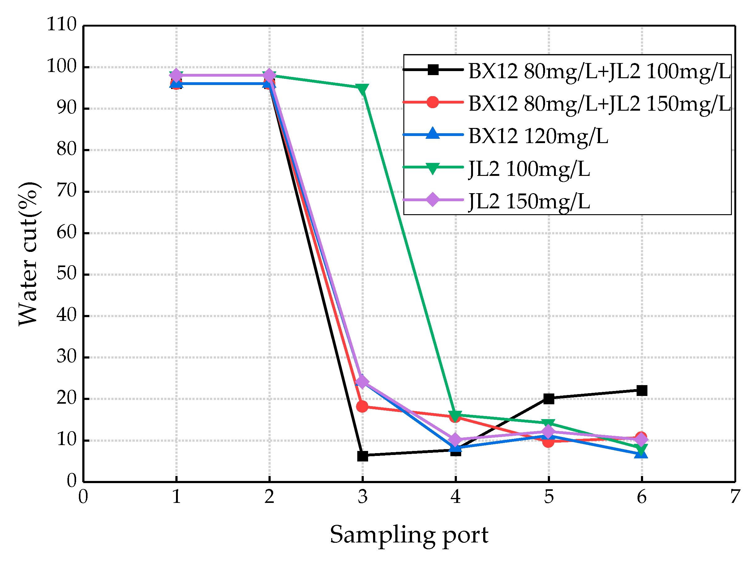
4.3. Influence of Chemicals on the Dehydration Effect

TWe tested he effects of two chemicals, the polyether demulsifier BX12 with phenolic resin as the initiator and the hyperbranched polyether revers demulsifier JL2 with organic amine as the initiator, on the dehydration effect of the device. The tests included five cases: (1) BX12 addition of 100 ppm, (2) BX12 addition of 150 ppm, (3) JL2 addition of 120 ppm, (4) BX12 80 ppm + JL2 100 ppm, and (5) BX12 80 ppm + JL2 150 ppm. During the testing period, the flow was 10 m3/h, the inlet water cut fluctuated between 90% and 96%, and the electric field and other parameters were basically consistent with the previous experiments.
The water cut of each sampling port for different chemicals and additions is shown in Figure 11. When the dosage of JL2 was 150 ppm, the overall dehydration effect was better than 100 ppm, and the effect of reducing the tension of the emulsified layer was better. Obviously, the dosage of the chemical JL2 had an influence on the dehydration efficiency, and within a certain range, the dehydration effect was better with the increase in the dosage chemicals of JL2. When the dosage of BX12 was 120 ppm, its dehydration rate was equal to or even higher than the dosage of JL2, which was 150 ppm. The weakening effect on the emulsified layer was best when the chemicals BX12 80 ppm + JL2 150 ppm were mixed; that is, the water cut of sampling ports 3 and 4 were the lowest. However, careful observation showed that the water cut at the oil outlet rose rather than fell. The analysis showed that when the dosage of the chemicals exceeded the optimal range, the molecules of the demulsifier began to aggregate into agglomerated micelles, which increased the oil–water interfacial tension, resulting in a decrease in the dehydration rate. Relatively speaking, when the chemicals BX12 80 ppm and JL2 100 ppm were mixed, the dehydration efficiency was ideal. However, this undoubtedly increases the costs.
After comprehensive consideration, we concluded that when the chemicals BX12 was used alone and the dosage was 120 ppm, the dehydration effect was best. However, the dehydration rate was only slightly increased, compared to when no chemicals were used. Therefore, we believe that the use of chemical agents has little effect on the dehydration efficiency of the electric-field-enhanced oil–water separator. This further shows that the electric-field-enhanced oil–water separation device has an excellent ability to break the routine, which not only reduces production costs, but also contributes to environmental protection.

5. Conclusions

The electric-field-enhanced oil–water separator showed a good dehydration effect for heavy oil with high water content. For the ABJ mixed liquid coming from the platform of 36-1CEPK in Suizhong, the frequency was ≥3500 Hz, the power supply voltage was 250 V, and the duty cycle was 8%, which are the optimal power supply operating parameters.
Taking the water cuts of different sampling ports and the overall dehydration rate as the evaluation index can accurately reflect the actual engineering application. Compared with small flow conditions, the dewatering advantage of the electric-field-enhanced oil–water separator is more obvious in the large flow conditions. Under the best working conditions, the heavy oil with water cut greater than 90% can be reduced to about 10%, and the dehydration rate can reach about 90%. In practical applications, the use of chemicals can be reduced or avoided. The dehydration problem of heavy oil with high water cut on offshore platforms is solved.
Compared with ordinary industrial three-phase separators, the overall dehydration rate was increased by about 15%. Our self-developed engineering prototype with a flow rate of 10 m3/h and a high-frequency/high-voltage AC pulse power supply, with the function of increasing voltage in stages within the pulse width, showed good performance in the oilfield test. It has been running stably in the Suizhong Oilfield for nearly 2 years. The research in this paper can provide evidence for the design and application of compact engineering prototypes in oilfields.

Author Contributions

Conceptualization, X.W., J.C., S.H., J.Z. and B.Z.; methodology, S.H., X.W., J.Z., J.C. and B.Z.; software, X.H. and J.D.; project administration, X.W., J.Z., J.C., S.H. and B.Z.; validation, J.Z., X.W. and S.H.; data curation, J.Z., X.W., S.H. and X.H.; writing—original draft, S.H., X.H. and J.D.; writing—review and editing, J.C., S.H., X.W. and X.H. All authors have read and agreed to the published version of the manuscript.

Funding

This research was funded by the National Natural Science Foundation of China Enterprise Innovation and Development Joint Fund (No. U20B2030), the Joint Fund of the Beijing Municipal Education Commission and Beijing Municipal Natural Science Foundation (No. KZ202010017026).

Institutional Review Board Statement

Not applicable.

Informed Consent Statement

Not applicable.

Data Availability Statement

Not applicable.

Acknowledgments

The authors acknowledge the financial support from the National Natural Science Foundation of China (No. 52274059).

Conflicts of Interest

The authors declare no conflict of interest.

References

  1. Urdahl, O.; Nordstad, K.; Berry, P.; Wayth, N.; Williams, T.; Bailey, A.; Thew, M. Development of a new, compact electrostatic coalescer concept. SPE Prod. Facil. 2001, 16, 4–8. [Google Scholar] [CrossRef]
  2. Bahú, J.O.; Miranda, N.T.; Khouri, N.G.; Batistella, C.B.; Concha, V.O.C.; Maciel, M.R.W.; Schiavon, M.I.R.B.; Filho, R.M. Crude oil emulsion breaking: An investigation about gravitational and rheological stability under demulsifiers action. J. Pet. Sci. Eng. 2022, 210, 110089. [Google Scholar] [CrossRef]
  3. Shi, Y.; Chen, J.; Pan, Z. Experimental study on the performance of a novel compact electrostatic coalescer with helical electrodes. Energies 2021, 14, 1733. [Google Scholar] [CrossRef]
  4. Chen, J.; Chu, Q.; Zhang, B.; Ding, Y.; Wang, C. Compact electrostatic pre-coalescence technology for crude oil dehydration (2). China Pet. Mach. 2009, 37, 77–82. [Google Scholar]
  5. Han, F.; He, Z.; Ye, T.; Guo, P. Coalescing assemblies structure optimization of compact electrostatic coalescer. Oil-Gasfield Surf. Eng. 2012, 31, 15–18. [Google Scholar]
  6. Mhatrea, S.; Vivacqua, V.; Ghadiri, M.; Abdullah, A.M.; Al-Marri, M.J.; Hassanpour, A.; Hewakandamby, B.; Azzopardi, B.; Kermani, B. Electrostatic phase separation: A review. Chem. Eng. Res. Des. 2015, 96, 177–195. [Google Scholar] [CrossRef]
  7. Parvasi, P.; Hesamedini, A.K.; Jahanmiri, A.; Rahimpour, M.R. A Comparative Study on Droplet Coalescence in Heavy Crude Oil Emulsions Subjected to Microwave and Ultrasonic Fields. Sep. Ence 2013, 48, 1591–1601. [Google Scholar] [CrossRef]
  8. Issaka, S.A.; Nour, A.H.; Yunus, R.M. Review on the fundamental aspects of petroleum oil emulsions and techniques of demulsification. J. Pet. Environ. Biotechnol. 2015, 6, 1. [Google Scholar] [CrossRef] [Green Version]
  9. Zhang, H.; Bukosky, S.C.; Ristenpart, W.D. Low-voltage electrical demulsification of oily wastewater. Ind. Eng. Chem. Res. 2018, 57, 8341–8347. [Google Scholar] [CrossRef]
  10. Wolff, E.A.; ABB Offshore Systems; Knutsen, T.L.; Hydro, N.; Piasecki, W.; ABB Corporate Research; Hansson, P.; ABB Offshore Systems; Nilsen, P.J.; ABB Offshore Systems. Advanced Electrostatic Internals in the 1st Stage Separator Enhance Oil/Water Separation and Reduce Chemicals Consumption on the Troll C Platform; Offshore Technology Conference: Houston, TX, USA, 2004; pp. 3–6. [Google Scholar]
  11. Lee, C.M.; Sams, G.W.; Wagner, J.P. Power consumption measurements for ac and pulsed dc for electrostatic coalescence of water-in-oil emulsions. J. Electrost. 2001, 53, 1–24. [Google Scholar] [CrossRef]
  12. Wood, D.J.; Kolbu, J.; Nilsen, P.J. Modelling of the VIEC-A New Device which Aids Separation. In Fourth International Conference on CFD in the Oil and Gas; Metallurgical & Process Industries, SINTEF/NTNU Trondheim: Trondheim, Norway, 2005; pp. 6–8. [Google Scholar]
  13. Fortuny, M.; Oliveira, C.B.Z.; Melo, R.L.F.V.; Nele, M.; Coutinho, R.C.C.; Santos, A.F. Effect of salinity, temperature, water content, and pH on the microwave demulsification of crude oil emulsions. Energy Fuels 2007, 21, 1358–1364. [Google Scholar] [CrossRef]
  14. Fjeldly, T.A.; Hansen, E.B.; Nilsen, P.J. Novel Coalescer Technology in First-Stage Separator Enables One-Stage Separation and Heavy-Oil Separation; Offshore Technology Conference: Houston, TX, USA, 2006; pp. 1–4. [Google Scholar]
  15. Less, S.; Hannisdal, A.; Bjørklund, E.; Sjöblom, J. Electrostatic destabilization of water-in-crude oil emulsions: Application to a real case and evaluation of the Aibel VIEC technology. Fuel 2008, 87, 2572–2581. [Google Scholar] [CrossRef]
  16. Aryafard, E.; Farsi, M.; Rahimpour, M.R. Modeling and simulation of crude oil desalting in an industrial plant considering mixing valve and electrostatic drum. Chem. Eng. Processing: Process Intensif. 2015, 95, 383–389. [Google Scholar] [CrossRef]
  17. Kakhki, N.A.; Farsi, M.; Rahimpour, M.R. Effect of current frequency on crude oil dehydration in an industrial electrostatic co-alescer. J. Taiwan Inst. Chem. Eng. 2016, 67, 1–10. [Google Scholar] [CrossRef]
  18. Kothmire, P.P.; Bhalerao, Y.J.; Naik, V.M. Experimental studies on the performance and analysis of an electrostatic coalescer under different electrostatic boundary conditions. Chem. Eng. Res. Des. 2020, 154, 273–282. [Google Scholar] [CrossRef]
  19. Mhatre, S.; Thaokar, R. Electrocoalescence in non-uniform electric fields: An experimental study. Chem. Eng. Processing Process Intensif. 2015, 96, 28–38. [Google Scholar] [CrossRef]
  20. Mhatre, S.; Deshmukh, S.; Thaokara, R.M. Electrocoalescence of a drop pair. Phys. Fluids 2015, 27, 092106. [Google Scholar] [CrossRef]
  21. Ismail, A.S.; Menchaca, A.E.; Balk, W.; Akdim, M.R. High-Performance Electrostatic Coalescer–A Novel Technology for Improving the Economics of Oil-Water Separation; Abu Dhabi International Petroleum Exhibition: Abu Dhabi, United Arab Emirates, 2020; pp. 9–12. [Google Scholar]
  22. Kharoua, N.; Khezzar, L.; Saadawi, H. CFD modelling of a horizontal three-phase separator: A population balance approach. Am. J. Fluid Dyn. 2013, 3, 101–118. [Google Scholar]
  23. Liu, Y.; Cheng, Q.; Zhang, B.; Tian, F. Three-phase hydrocyclone separator–A review. Chem. Eng. Res. Des. 2015, 100, 554–560. [Google Scholar] [CrossRef]
  24. Piasecki, W.; Florkowski, M.; Fulczyk, M.; Sipowicz, J. Vessel Internal Electrostatic Coalescer (VIEC) Novel oil-water separation technology. Innov. Eng. 2004, 4, 69–70. [Google Scholar]
  25. Song, F.; Wang, W.; Chen, Q.; Fan, J. Coalescence characteristics of the double droplets under electric field. CIESC J. 2021, 72, 371–381. [Google Scholar]
  26. Zhang, L.; Chen, J.; Li, W.; Zhuang, G.; Hu, C.; Xi, J.; Meng, H. Three-phase separation and electric field demulsification and dehydration integration (VIEC) technology and its performance research. Pet. Plan. Eng. 2017, 28, 8–12+16+54. [Google Scholar]
  27. Zhang, J.; He, H.; Huang, G. Simulation of droplet deformation in uniform electric field with dissipative particle dynamics approach. CIESC J. 2014, 65, 3872–3877. [Google Scholar]
  28. Hiesa, M.; Melheim, J.; Pedersen, A.; Ingebrigtsen, S.; Berg, G. Forces acting on water droplets falling in oil under the influence of an electric field: Numerical predictions versus experimental observations. Eur. J. Mech. B/Fluids 2005, 24, 717–732. [Google Scholar]
  29. Pethig, R. Dielectrophoresis: Status of the theory, technology, and applications. Biomicrofluidics 2010, 4, 022811. [Google Scholar] [CrossRef] [PubMed] [Green Version]
  30. Olson, M.D.; Grave, E.J.; Juarez, J.C.; Gul, K. Performance Testing of an Integrated, Subsea Compact Separation System with Elec-trocoalescence for Deepwater Applications; Offshore Technology Conference: Houston, TX, USA, 2015; pp. 4–7. [Google Scholar]
  31. Ni, L.; He, L. Experimental Studies of Separating Behavior of Gravitational Oil-Water Separator with a Coalescing Internal Installed. Oil Field Equip. 2007, 10, 61–64. [Google Scholar]
  32. AlQahtani, A. Vessel Internal Electrostatic Coalescer Technology (VIEC); International Production and Operations Conference & Exhibition: Doha, Qatar, 2012; pp. 66–70. [Google Scholar]
  33. Zhang, M.; Shang, C.; Wang, H.; Zheng, X.; Wang, C. Prospect of offshore electrostatic coalescence crude oil dehydration technology. Ocean. En-Gineering Equip. Technol. 2017, 4, 86–90. [Google Scholar]
  34. Xu, M.; Zhang, Z.; Hao, B.; Shen, B.; Lv, Z. Application of novel electrostatic coalescence dehydration technology in oil-water separator. China Offshore Platf. 2020, 35, 84–89. [Google Scholar]
  35. Raya, S.A.; Mohd Saaid, I.; Abbas Ahmed, A.; Umar, A.A. A critical review of development and demulsification mechanisms of crude oil emulsion in the petroleum industry. J. Pet. Explor. Prod. Technol. 2020, 10, 1711–1728. [Google Scholar] [CrossRef] [Green Version]
  36. Xiong, H.; Zhang, B.; Chen, J.; Hu, C.; Zhang, X.; Huang, S.; Xi, J. Crude oil dehydration technology by vessel internal electrostatic coalescer in three-phase separator. China Pet. Mach. 2016, 44, 108–112. [Google Scholar]
  37. Zhang, L.; Xiao, H.; Zhang, H.; Xu, L.; Zhang, D. Optimal design of a novel oil–water separator for raw oil produced from ASP flooding. J. Pet. Sci. Eng. 2007, 59, 213–218. [Google Scholar] [CrossRef]
  38. Huang, S.; He, X.; Li, W.; Jiao, X.; Chen, J. An AC Pulse Crude Oil Dehydration Power Supply Device with the Function of Increasing the Voltage in Sections within the Pulse Width. China Patent CN113179028A, 27 July 2021. [Google Scholar]
  39. Tang, X.; Zhang, Y.; Wang, X.; Chen, J. Application research of electric field enhanced oil-water separation in oilfield produced liquid. Ind. Water Treat. 2022, 42, 168–171+177. [Google Scholar]
  40. Kang, W.; Li, M.; Yang, H.; Kang, X.; Wang, F.; Jiang, H.; Zhang, M.; Zhu, T.; Sarsenbekuly, B. Coalescence behavior of aqueous drops in water-in-oil emulsions under high-frequency pulsed AC fields. J. Ind. Eng. Chem. 2021, 93, 415–422. [Google Scholar] [CrossRef]
  41. Dong, J.; Chen, J.; Ji, Y.; Wang, C.; Shang, C.; Zhang, M. Performance test of compact tubular high-voltage electric field coalescers. Process Eng. 2021, 40, 1390–1400. [Google Scholar]
  42. Shi, Y.; Chen, J.; Meng, H. Experimental study on the performance of an electric field enhanced separator for crude oil production fluid. J. Pet. Sci. Eng. 2022, 212, 110315. [Google Scholar] [CrossRef]
Figure 1. Schematic diagram of the electrostatic coalescence process.
Jmse 10 01516 g001
Figure 2. Dipole force model for conductive droplets.
Jmse 10 01516 g002
Figure 3. Internal overall layout of the electric-field-enhanced three-phase separator.
Jmse 10 01516 g003
Figure 4. Schematic diagram of the installation position of each component inside the separator.
Jmse 10 01516 g004
Figure 5. (a) Theoretical model diagram of coalescent packing assembly; (b) the actual appearance of coalescent packing assembly.
Jmse 10 01516 g005
Figure 6. (a) Schematic diagram of the built-in electrode assembly and a close-up of insulated electrode structure; (b) the actual appearance of the alternating metallic and insulating electrodes.
Jmse 10 01516 g006
Figure 7. Droplet settling and floating curve inside the electric field-enhanced three-phase separator tank.
Jmse 10 01516 g007
Figure 8. Schematic diagram of the overall structure of the test prototype.
Jmse 10 01516 g008
Figure 9. The water cut of oil and the dehydration rate in different pulse frequencies.
Jmse 10 01516 g009
Figure 10. The average water cut of each sampling port in the VIEC power-on and power-off test under the large flow conditions.
Jmse 10 01516 g010
Figure 11. Water cut of each sampling ports under different chemicals and addition.
Jmse 10 01516 g011
Table 1. The process parameters of the pilot test platform.
ParameterValueParameterValue
Design flowrate10 m3/hWater density at 50 °C992 kg/m3
Tank size5.2 m × 2.4 m × 3.695 mOil density at 50 °C932 kg/m3
Water content90%Oil viscosity at 50 °C6.47 × 10−3 Pa·s
Temperature50 °CWater viscosity at 50 °C5.57 × 10−4 Pa·s
Table 2. The water cut of each sampling port in the VIEC power-on and power-off test at different inlet flows.
Flow (m3/h)Inlet Water Cut (%)Water Cut of Each Sampling Point (%)Dehydration Rate (%)VIEC Power
1234567
6.5909092383725151682.2Off
869898323016211681.4
78------1284.6On
82------1285.4
10909595343121121583.3Off
969696424135242771.9
951001002222.5118891.6On
901001002019126693.3
Publisher’s Note: MDPI stays neutral with regard to jurisdictional claims in published maps and institutional affiliations.

