Article

Research on the Hydrodynamic Performance of a Horizontal-Axis Tidal Current Turbine with Symmetrical Airfoil Blades Based on Swept-Back Models

1
Key Laboratory of Advanced Energy Development and Application Innovation under Jilin Province, School of Physics, Northeast Normal University, Changchun 130024, China
2
School of Energy and Power Engineering, Changchun Institute of Technology, Changchun 130012, China
*
Author to whom correspondence should be addressed.
J. Mar. Sci. Eng. 2022, 10(10), 1515; https://doi.org/10.3390/jmse10101515
Submission received: 11 September 2022 / Revised: 29 September 2022 / Accepted: 15 October 2022 / Published: 17 October 2022
(This article belongs to the Special Issue Tidal and Ocean Current Energy)

Abstract

:
For the design of a horizontal-axis tidal current turbine with adaptive variable-pitch blades, both numerical simulations and physical model experiments were used to study the hydrodynamic performance of symmetrical airfoil blades based on backward swept models. According to the lift–drag ratio of symmetrical airfoils, variable airfoil sections were selected for each part of the blade in the spanwise direction. Then, three kinds of blades were designed by using different swept-back models from wind turbines. A rotation model with a multi-reference frame was employed to conduct a three-dimensional steady numerical simulation of the turbine model based on the CFD method. The axial thrust and energy-capturing efficiency under different tip speed ratios, as well as the corresponding starting torque under different flow rates, were analyzed. The simulation results indicate that model 2 has optimal start-up performance, and model 3 has the largest power coefficient. The thrust coefficient of model 1 is the smallest. In all, model 2 has better comprehensive performance. The experiments of model 2 show that it has suitable hydrodynamic performance to capture bidirectional energy via passively variable pitch. This research provides an important solution for the design and optimization of horizontal-axis turbines to harvest bidirectional tidal current energy.

1. Introduction

The effective utilization of marine renewable energy is one important way to achieve the carbon peaking and carbon neutrality goals of China. Tidal current energy is a type of marine renewable energy that has the features of abundant reserves, stability, regularity, and so on [1,2,3]. The horizontal-axis turbine is the core component of the tidal current energy conversion device used to capture energy, which has the advantages of stability, high efficiency, and large self-starting torque [4]. The optimal design of the turbine is essential to improve its energy conversion efficiency and reliability, which are the key issues for the research of the tidal current energy generation system. Some have studies shown that the swept-back blade, as an optimal layout method, can significantly enhance the passive pitch characteristic of the turbine, and also has important influences on other hydrodynamic performances of the turbine [5].
Swept-back blades have been widely applied to wind turbines [6,7,8,9], but theoretical and experimental research is rare in the field of tidal current turbines. Kaya et al. found that the backward swept blades of wind turbines tend to reduce the thrust coefficient, and various swept offsets and swept starting positions have different effects on the thrust coefficient. For the backward swept blade with the starting position close to the blade tip and larger offset, the thrust drop is more obvious [6]. Hansen studied the influence of nonlinear coupling of blades with different swept shapes on the power and thrust coefficients, which explained the reason for the load with swept blades [7]. Larwood et al. pointed out that the blade tip offset has the greatest impact on the energy generation and blade load, indicating that the larger the blade tip offsets, the lower the load acts [8]. Khalafallah et al. investigated different swept starting points and swept directions under various tip speed ratios (TSRs) by numerical simulation. The results showed that at a high TSR, the energy harvesting efficiency of the downstream sweeping blade is higher than that of the straight blade, but it has a larger axial thrust [10]. Amano et al. found that the swept-back blades generate greater power than that of the straight blades at lower wind speeds, whereas the straight blades obtain less energy at higher wind speeds [11]. For a generic 5MW NREL wind turbine model, Verelst and Larsen studied 120 different backward swept and forward swept blades, and found that backward swept blades can reduce fatigue loads but have lower energy harvesting efficiency at rated conditions, and the forward swept blades increase fatigue loads [12]. In terms of variable-pitch symmetrical airfoil blades for tidal current energy turbines, the swept design was first introduced by our group. The model experiments and field tests showed that this method can effectively improve the blade pitch efficiency [13]. For the general-purpose design of tidal current turbine blades, Blade Element Momentum (BEM) and its correction theory are usually used to provide theoretical supports for hydrodynamic performance analysis of the turbines [14]. A modified BEM-CFD method proposed by Edmunds et al. solves the problem of the tip loss not being accurately determined by changing the angle of attack. The power coefficient has been enhanced dramatically compared to the experimental data [15]. Based on the BEM theory, Ma et al. [16] applied the optimal blade design approach for variable-speed operation based on the BEM theory to design the chord length and the pitch angle of the blade. A mathematical model was developed to forecast the hydrodynamic performance of the turbine by using the blade tip and hub loss correction theory. The results revealed that the experimental data are in good accordance with the theoretical value, indicating that the BEM theoretical prediction is reasonable. To predict the hydrodynamic performance of the turbine under certain working conditions, ANSYS Fluent software is mostly applied for the numerical modeling and simulation of the model turbine [17,18]. The system coupling module in ANSYS software can also be used for fluid-structure coupling analysis to calculate the influence of blade structure changes on the hydrodynamic performance of the turbine [19]. The numerical calculation results have good accuracy in predicting the performance of the turbine, which can provide a certain reference for the design of the tidal stream energy turbine [20].
In order to further study the influence of backward swept design on the hydrodynamic performance of adaptive variable-pitch symmetrical airfoil blades, three kinds of blades with different backward swept models are presented in this paper. The software of SolidWorks was used to build the 3D model of the hydraulic turbine. Based on the pre-processing software ICEM CFD, the solver Fluent, and the post-processing software CFD-Post, axial thrust coefficient, energy acquisition characteristics, and starting torque of the turbine models were analyzed and discussed. In addition, physical model experiments of the selected model were carried out to verify the performance of the numerical simulation.

2. Backward Swept Blade Design

2.1. Initial Model

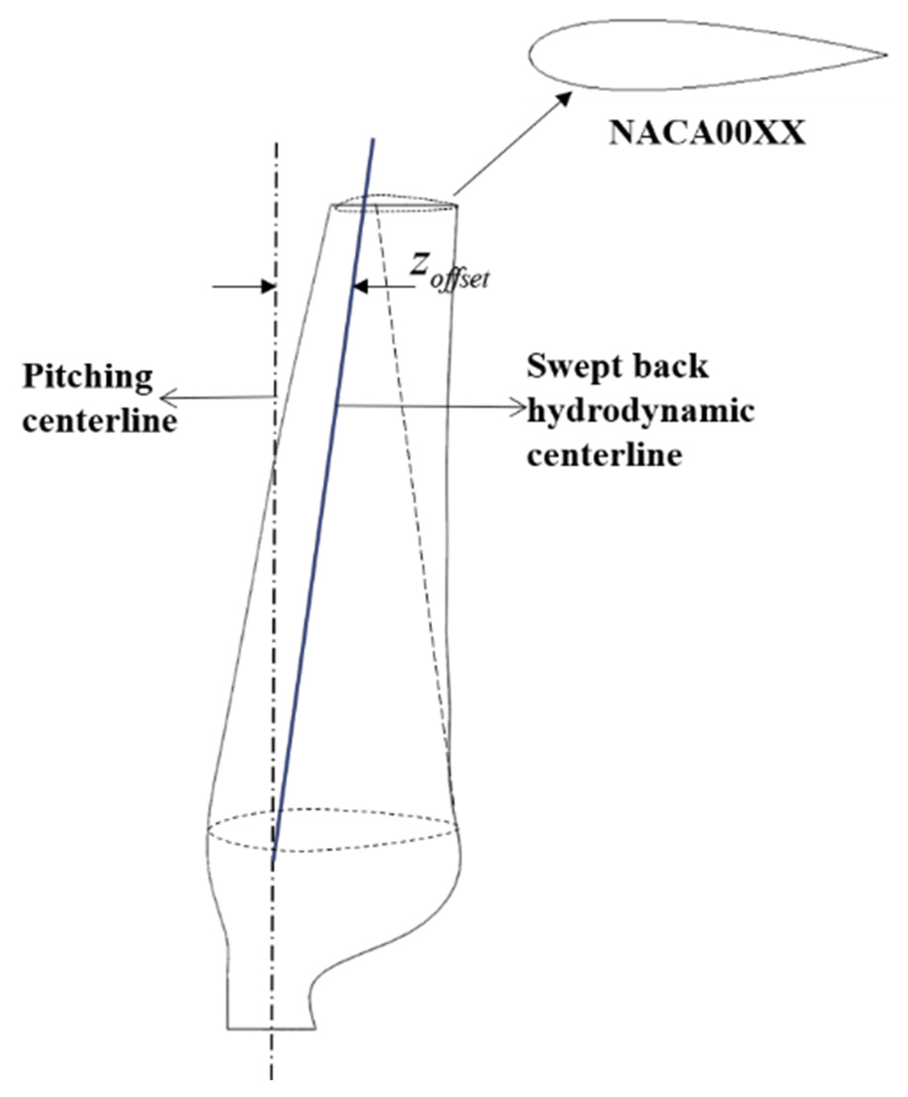
In the initial blade design, a thicker NACA0030 airfoil was selected at the blade root for transition to meet the strength requirements at the blade root. Different sections along the blade span have different angles of attack. The airfoil with the maximum lift–drag ratio at the best angle of attack for each section was selected for the initial blade design. In other words, different airfoils were selected in turn along the spanwise direction to design the segmented airfoils, and the swept-back symmetrical airfoil blades were optimized by the variable section design. The initial model has no swept design, that is, its pitch centerline coincides with the hydro-dynamic centerline, as shown in Figure 1. Thus, there is not an effective torque under the action of the hydrodynamics to make the blade pitch passively. The blade design of the initial model in this paper is based on the modified BEM theory, and the fmincon function in the Matlab optimization toolbox was used to iteratively solve the design target of the maximum power output of a single section of the blade, and then the chord length of the blade was obtained. The initial turbine radius R is 166 mm. The diameter and the length of the hub are 50 mm and 62 mm, respectively. The pitch angle is 6°. Table 1 shows the specific design parameters of the initial blades.

2.2. Swept Model

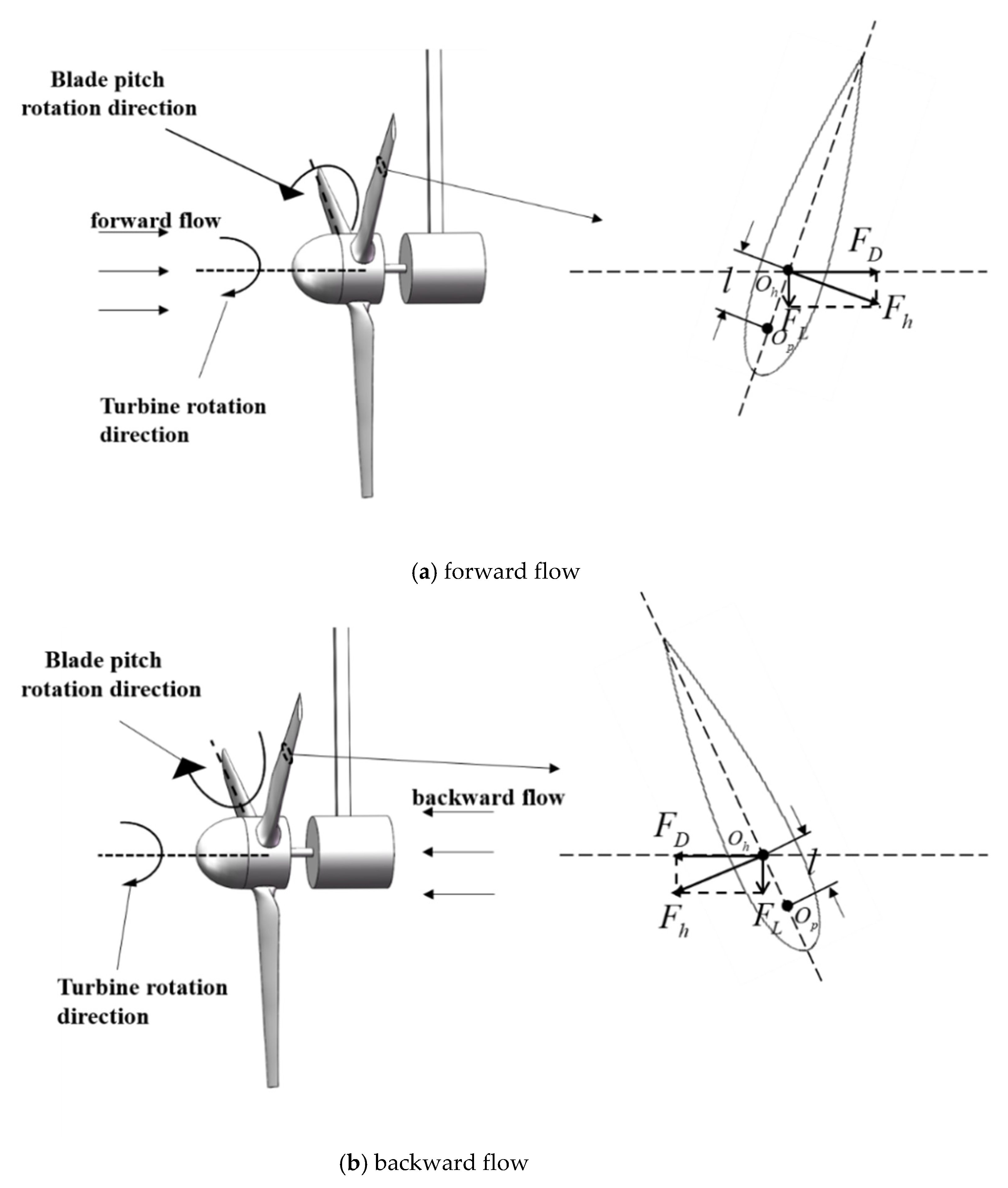
The adaptive variable-pitch approach of horizontal-axis tidal current turbines proposed by our group relies on the deflection moment of the hydrodynamic force generated by the symmetrical airfoil blades relative to the pitching axis of the blade under the water flow, as shown in Figure 2. Through sweeping, the hydrodynamic center O h of the blade element is closer to the trailing edge than its pitching center O p , as shown in Figure 3. Thus, there is a moment arm l between the hydrodynamic center and the pitching center. Then, under the resultant force F h from the lift F L and the drag F D , a pitching torque relative to O p will be produced, which is illustrated in Figure 3a for the forward flow and in Figure 3b for the backward flow.
To increase the pitch torque as much as possible, the initial swept offset position of the model in this paper is set at 35% of the blade span, the hydrodynamic center of each section is offset to the trailing edge, and the tip offset reaches the maximum value, which was designed to be 10%R.
The swept design methods derive from references [6,7,8]. Kaya et al. [6] studied the influence of different offsets of wind turbine swept blades and the starting position of swept blades on the thrust coefficient. Hansen et al. [7] investigated the influence of the torsion and bending moment coupling of the swept blade on the static and dynamic performance of the blade, and calculated the aerodynamic power and thrust of the blade with different swept shapes. The applied model comprehensively considers the influence of linear and quadratic functions and sweep curvature on sweep. Larwood et al. [8] conducted a study on the design parameters of wind turbine swept blades and found that in addition to the tip offset, which has a greater impact on energy harvesting and blade load, other parameters have less impact. Table 2 presents the sweep offset equations for the three models.
Among the above three equations, z o f f s e t is the blade section offset. R represents the rotor radius, which is 0.166 m in this study. r r is the radius of the section. r s t a r t is the radius of the section at the backward swept starting position, which is 35% of the rotor radius. P s is the ratio of the tip offset to the rotor radius ( P s   =   d / R ), where d is 10% of the rotor radius. R   ×   P s denotes the deflection of the blade at the tip. P r is the ratio of the radius of the section to the radius of the rotor ( P r   =   r r / R ). P r s t a r t is the ratio of the radius of the section at the backward swept starting position to the radius of the rotor. M represents the sweep strength ( P r s t a r t   =   r s t a r t / R ), and M = 2 was chosen to represent the average sweep strength. a and b are constants, and their selections can refer to [7]. Here, a and b are 9 and 25, respectively. γ is expressed as the equation offset exponent, and the exponent was chosen to be 2 in this paper. The specific swept model parameters are shown in Figure 4.
According to Table 2 and the values of related parameters above, the offset values calculated by each model are shown in Table 3. Figure 5 presents the comparison of offsets for different models under different radial distributions. Obviously, among these three models, the overall offset of model 1 is the largest, and that of model 3 is the smallest.

2.3. 3D Model

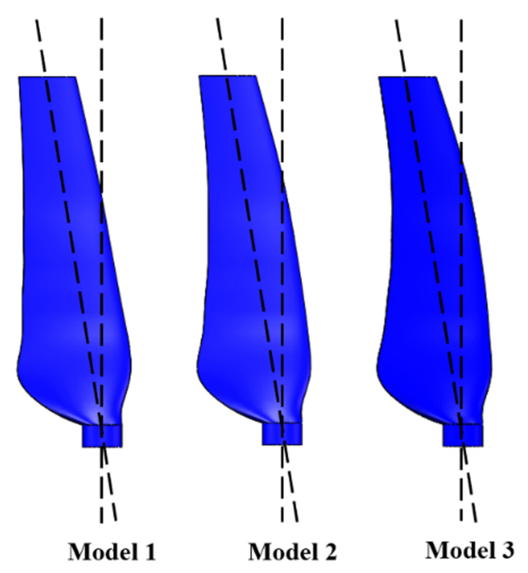
According to the corresponding section offsets of different models shown in Table 3, the 3D models of three different swept blades and the overall 3D model of the turbine were constructed in SolidWorks software, as shown in Figure 6 and Figure 7, respectively.

3. Numerical Simulation

3.1. Meshing

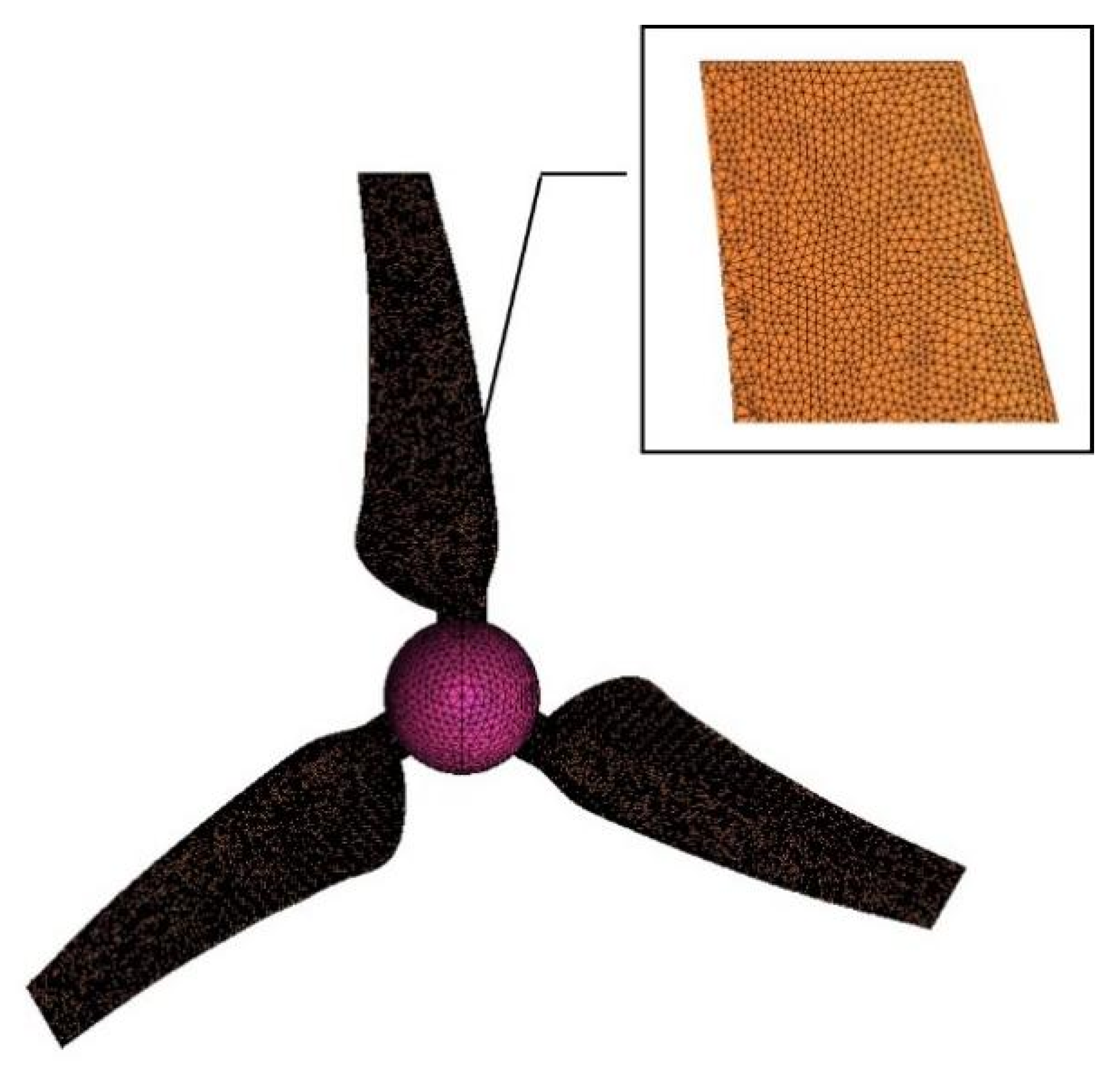
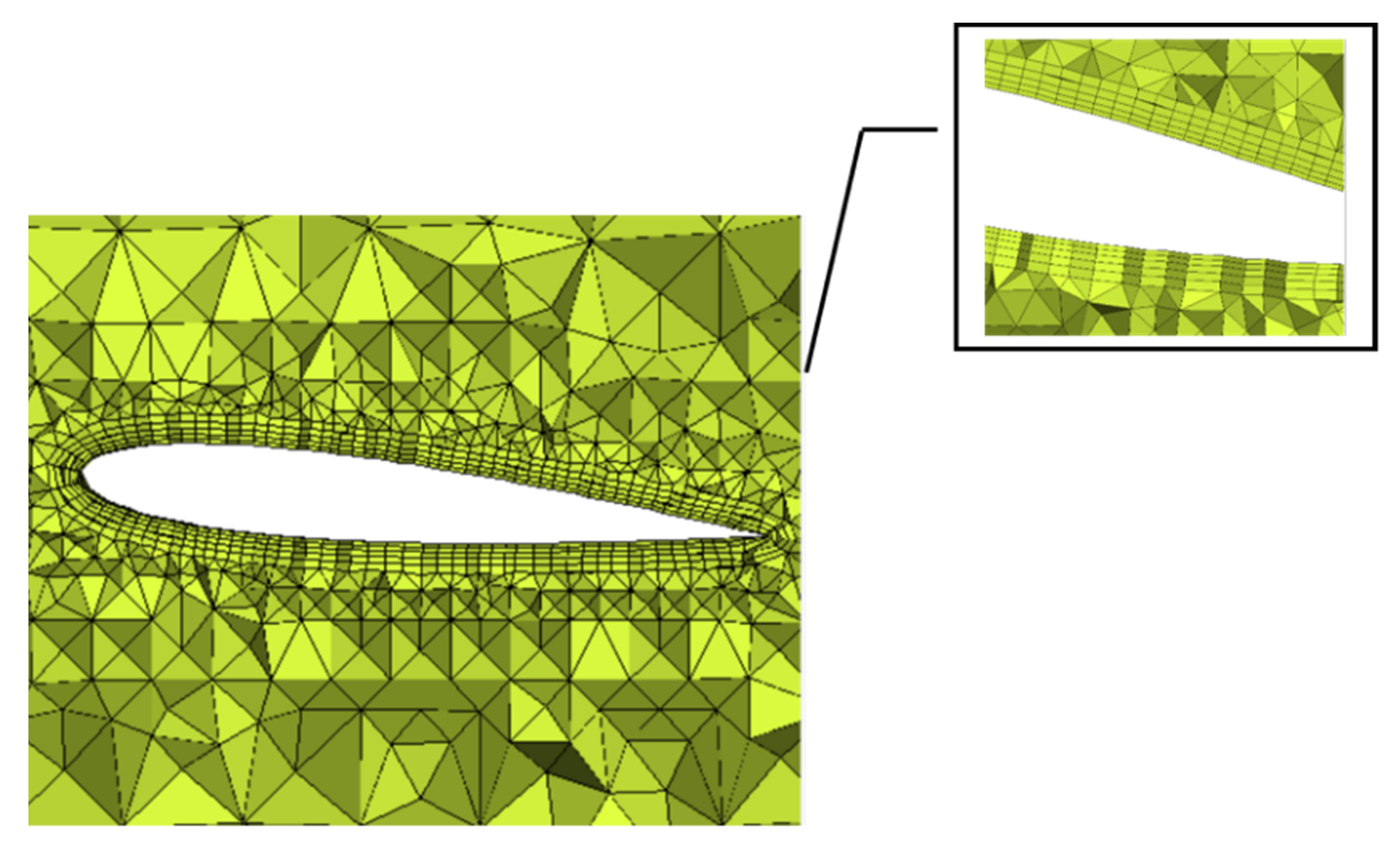
For the numerical modeling and simulation of the turbine model based on the Computational Fluid Dynamics (CFD) method, the pre-processing software ICEM CFD was adopted to generate and optimize the grid. The mesh division needs to consider the quality of the mesh and the computer capability, select the unstructured tetrahedral mesh, and perform mesh division after setting other basic parameters. Figure 8 shows the mesh of the blade surface and its partial enlargement feature. It should be noted that the height of the first layer grid node of the boundary layer can be calculated by y+. After calculating the Reynolds number, wall friction coefficient, wall shear stress, and estimated velocity, the boundary layer height of the first layer is 0.25 mm. The boundary layer after meshing and its local enlarged features are shown in Figure 9.

3.2. Mesh Independence Analysis

By employing the CFD method to carry out numerical simulation so as to predict the power coefficient of the tidal current turbine, the accuracy and economy of the scheme should be considered. The number of nodes generated by the above scheme is about 500,000, and the total number of grids is about 2.06 million. Grid independence testing is required. For this model, five kinds of grid refinement methods are discussed, and the grids are refined, respectively, in the inner domain and outer domain. The calculation results of different numbers of nodes and grids are obtained, as shown in Table 4.
It can be seen from Table 4 that when the number of grids increases in multiples, the power coefficient does not change significantly, indicating that the increase in the total number of grids does not mean that the energy efficiency will definitely increase. Within the limit range of grid density, the denser the grid, the higher the calculation accuracy is. According to the comparison of scheme 5 and scheme 4, it is obvious that beyond this limit, further densification could not improve the accuracy effectively. When exceeding the mesh density limit, the number of different meshes will not have a great impact on the simulation results. In general, the mesh in scheme 4 has achieved a relatively ideal prediction effect. Considering the efficiency of computing resource allocation and simulation, the more the grids, the longer the computing time takes, so scheme 4 could be selected for the subsequent simulation.

3.3. Calculation and Post-Processing

The finite volume solver Fluent was employed to solve the three-dimensional incompressible Reynolds-averaged Navier-Stokes (RANS) equation. Furthermore, the k ε turbulence model, which is the most widely used in industrial flow calculation, was used to simulate the turbulence in the water flow, where the equation was closed. The rotating coordinate system, combined with the method of Multiple Reference Frame (MRF), was applied for the rotation of the turbine in the inner watershed. In addition, the post-processing software CFD-Post was harnessed to analyze the simulation results. As shown in Figure 10, the boundary condition of the computational domain inlet was set to the velocity inlet. The outlet was subjected to a static pressure-outlet boundary condition. The surrounding boundary of the computational domain was defined by a fixed wall condition. The non-slip rotating wall condition was applied on the blade and hub surface. The rotational domain’s relationship to the computational domain was set as an interior condition. The convective term was discretized by the second-order incoming flow scheme. Then, the Simple algorithm was used to achieve the coupling between pressure and velocity, and the residual of each block was reduced to less than 10−3 to converge.

4. Analysis of Simulation Results

4.1. Starting Torque

The starting torque is the torque of the stationary blade under water flow. Table 5 shows the model starting torque corresponding to the change of the velocity range from 0.2 m/s to 0.5 m/s. According to the data, the starting torque of all the three models increases with the increase of the flow speed. Different backward swept methods have a certain influence on the starting performance. However, due to the small initial design size of the models, the difference in starting performance is small. In comparison, model 1 has the smallest starting torque, and the other two models have a small increase compared with model 1. Among them, the increase amplitude of model 2 is larger than that of model 3. When the flow velocity is 0.2 m/s, the increments of models 2 and 3 are the largest, which are 1.53% and 0.18%, respectively. With its relatively good start-up characteristics, model 2 can be used as the optimal choice among the three models in applications with lower requirements for the design index of start-up flow velocity.

4.2. Energy Efficiency Analysis

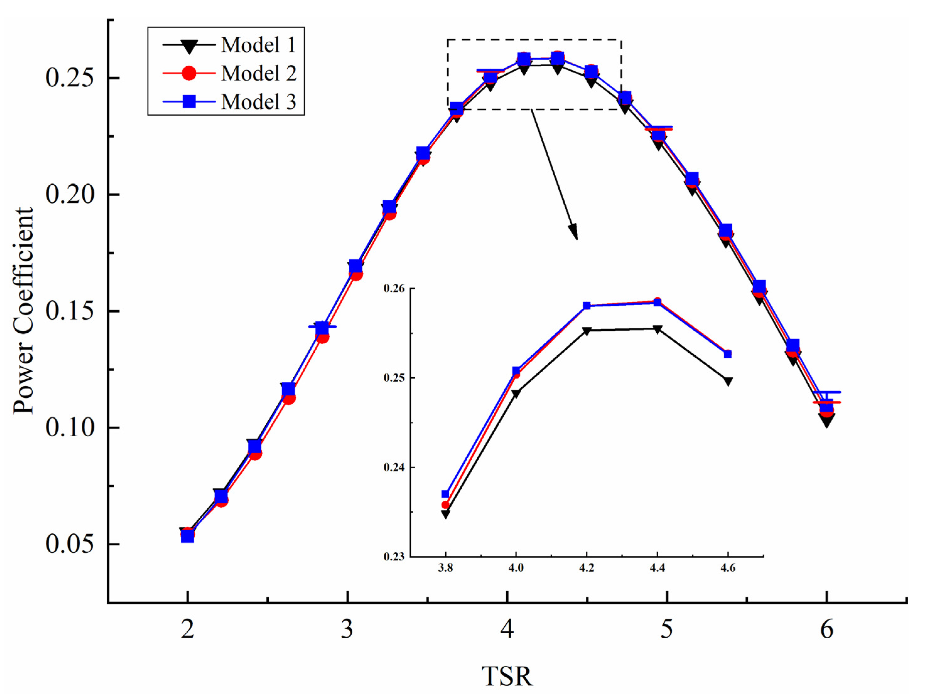
Figure 11 presents the variation trend of the energy-harvesting efficiency with increasing TSR at the flow velocity of 0.4 m/s. The typical power coefficient values at several TSRs, as well as corresponding comparison, are shown in Table 6.
It can be seen from Figure 11 that the captured energy of the three swept-back models increases first and then decreases with the increasing TSR. When the TSR is about 4, the power coefficient of each model is maximized. At the TSR of 2, the power coefficient of model 3 is the smallest. Compared with model 1, the power coefficients of models 2 and 3 are reduced by 1.35% and 2.86%, respectively. Meanwhile at the TSR of 3, the power coefficient of model 2 is the smallest, and the power coefficients of model 1 and model 3 are increased by 1.92% and 2.21%, respectively, compared with that of model 2. In the range of high TSR from 4 to 6, model 2 and model 3 show good energy harvesting characteristics. Compared with model 1, the power coefficients of both model 2 and model 3 increase, and model 3 has a larger increase than model 2, where the corresponding values are increased by 3.22% and 5.17%, respectively. Generally speaking, when only considering the energy efficiency, model 3 is superior to the other two models.

4.3. Load Analysis

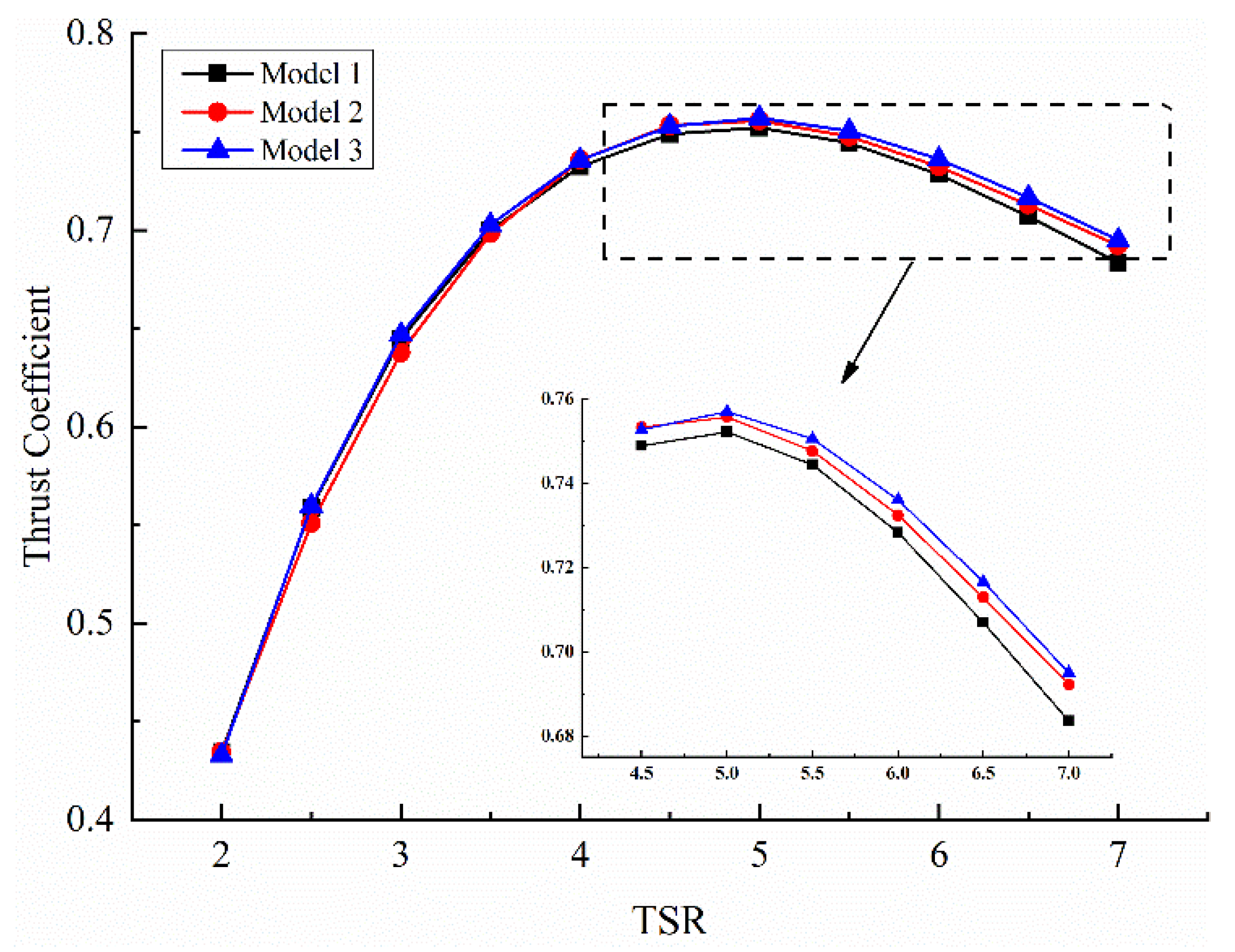
The thrust coefficient obtained by numerical simulation is shown in Figure 12. The thrust coefficients and corresponding comparisons at certain TSRs are shown in Table 7. The overall thrust trend of the three groups of models increases first and then decreases with the increasing TSR, and the thrust coefficient decreases when TSR is greater than 5. When the TSR is less than 4, the thrust load of model 3 is the smallest, and the thrust loads of model 1 and model 2 increase by 0.33% and 0.36%, respectively, compared with model 3. For the TSR more than 4 or equal to 4, the thrust load of model 1 is the smallest, and that of model 3 is the largest. When the optimum TSR is 4, the thrust load of model 3 is increased by 0.63% compared with that of model 1. Apparently, model 1 can perform better in practical applications to minimize the thrust load on the turbine as much as possible.

5. Experimental Verification

According to the above simulation analysis, model 2 has the optimal starting performance, which is especially suitable for the utilization of the tidal current resource with low velocity in most areas of China. For the characteristics of energy-capturing efficiency and thrust load, model 2 is between the other two models. Furthermore, the power coefficient of model 2 is only a little less than that of model 3 at high TSR. Therefore, model 2 was selected as the optimal design. To verify the numerical simulation, it is very necessary to carry out physical model experiments. Figure 13 shows the model experiment test platform. The hydrodynamic performances of the turbine were analyzed by measuring the torque, rotational speed, and thrust of the turbine when the flow velocity was 0.4 m/s.
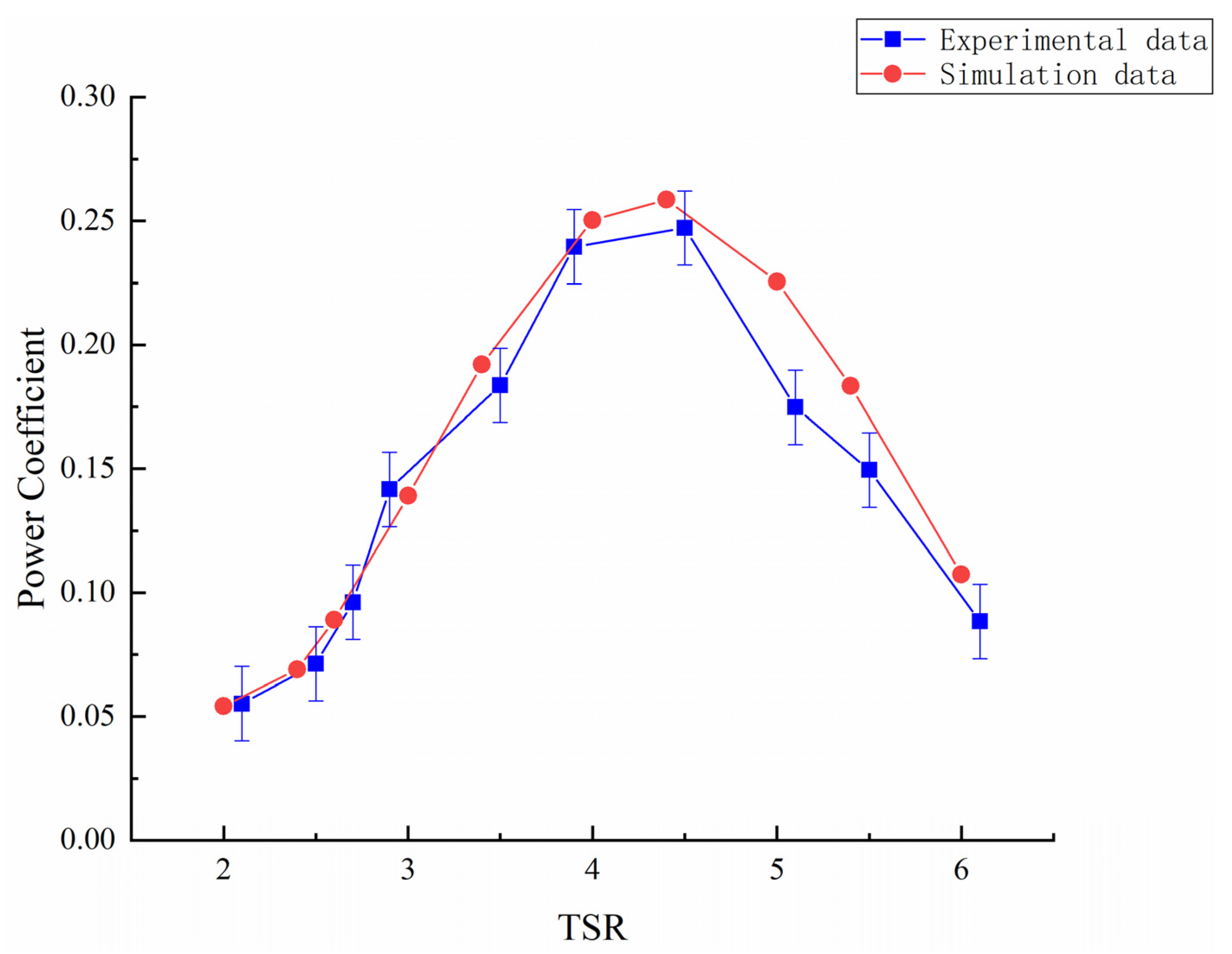
Figure 14 presents the comparison results between the experimental data and the simulation data of the power coefficient of the turbine under different TSRs. It can be seen that the power coefficient obtained from the simulation data and the experimental data shows a trend of first increasing and then decreasing with the increasing TSR. When the TSR is about 4.5, the power coefficient is nearly the largest, which is 0.247. When the TSR is less than 3, the experimental data are close to the simulation value. For TSR values from 3 to 6, the experimental data are smaller than the simulation value. This is because the simulation calculation is in ideal conditions, and the energy loss is small. However, the numerical simulation could generally reflect the energy harvesting feature of the turbine.
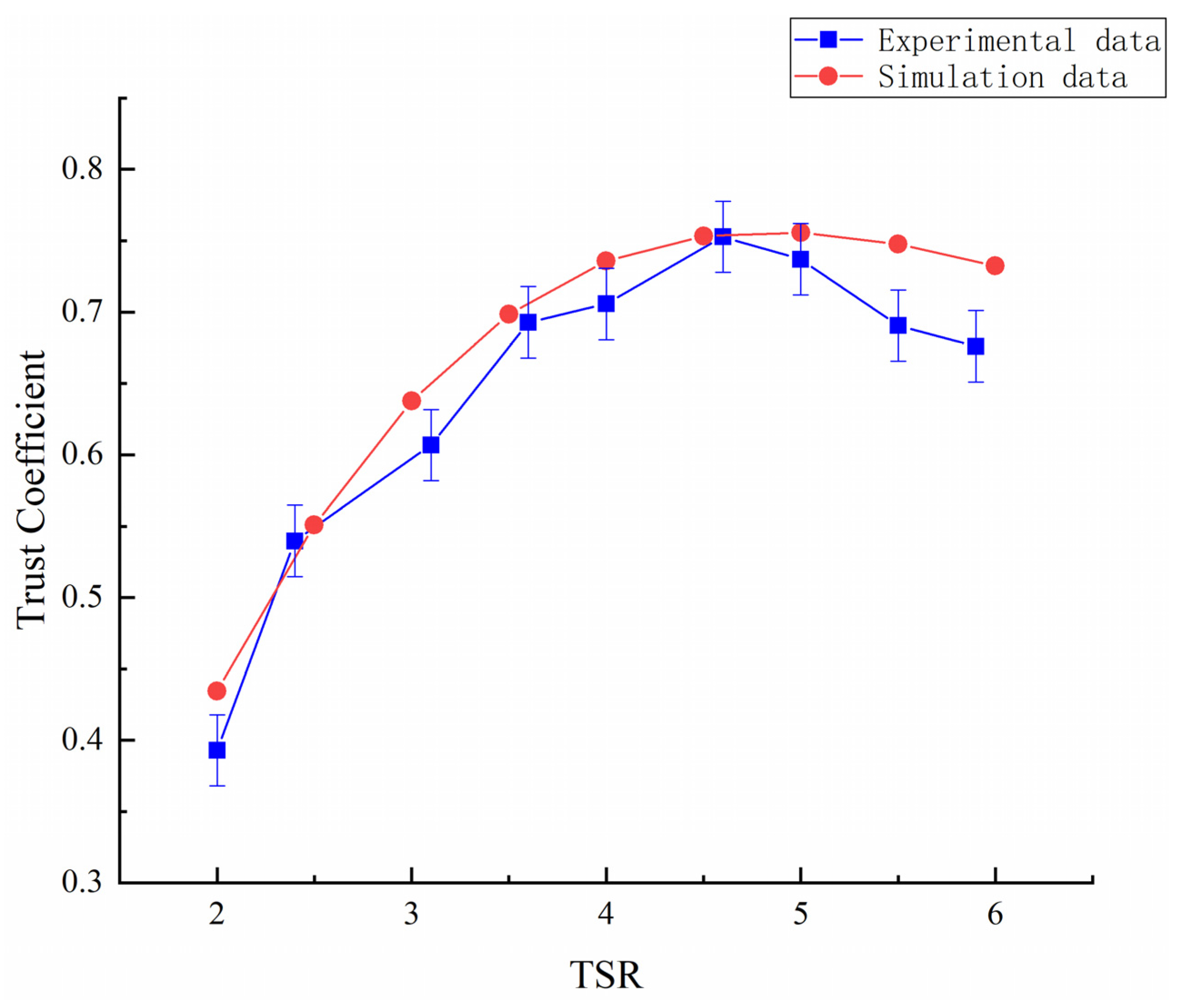
Figure 15 presents the comparison results between the experimental data and the simulation data of the trust coefficient of the turbine under various TSRs. The results illustrate that the change trend of the thrust coefficient is roughly the same in the two environments of the experiment and the numerical simulation. When the TSR is 4.6, the thrust coefficient is 0.75278, which is close to the design condition. When the TSR is greater than 4.6, the simulation value is greater than the test value. As for when the TSR is less than 4.6, the experimental value is similar to the simulation value. In general, the variation trend of the numerical simulation is the same as that of the experimental data, which could be used to predict the thrust performance of the turbine.

6. Conclusions

In this paper, swept-back symmetrical airfoil blades were designed based on three kinds of swept design methods, and the influence of different designs on the hydrodynamic performance of the adaptive variable pitch blade was discussed. Through SolidWorks modeling and CFD simulation, starting torque, power coefficient, and load conditions of the three models were analyzed. When considering the starting performance, the starting torques of model 2 and model 3 have increased values compared with that of model 1, and the maximum increasing value of model 2 is 1.53%. For the energy harvesting efficiency, model 2 and model 3 show better power characteristics than model 1, where the corresponding power coefficient has been increased by 3.22% and 5.17%, respectively. When considering the thrust characteristics, the load coefficient of model 2 is also between model 1 and model 3. For the application of tidal current resource with low velocity in most areas of China, model 2 is the best choice among these three models, which could harvest low-speed tidal current energy more effectively, while the increase of the thrust load is not very obvious. In addition, the water tank experiment of model 2 showed that the experimental data of thrust load and energy harvesting efficiency under different TSRs have the same trend as the numerical simulation, which verifies the rationality of the numerical simulation. This study can provide an important reference for the design and optimization of the adaptive variable pitch turbine.

Author Contributions

Conceptualization, Y.-J.D.; methodology, Y.-J.D. and C.L.; software, X.Z. and S.-M.X.; writing—original draft preparation, C.L. and Y.-T.Y.; writing—review and editing, Y.-J.D.; supervision, J.-M.C. and X.-M.Z. All authors have read and agreed to the published version of the manuscript.

Funding

This research was funded by “the National Key Research and Development Project of the Ministry of Science and Technology of China—NKRDPMST, grant number 2018YFB1501903-03” and Jilin Provincial Department of Education Scientific Research Project—JPDESRP, grant number JJKH20221165KJ”.

Institutional Review Board Statement

Not applicable.

Informed Consent Statement

Not applicable.

Data Availability Statement

Not applicable.

Conflicts of Interest

The authors declare no conflict of interest.

References

  1. Zhang, D.; Wang, J.; Lin, Y.; Si, Y.; Huang, C.; Yang, J.; Huang, B.; Li, W. Present situation and future prospect of renewable energy in China. Renew. Sustain. Energy Rev. 2017, 76, 865–871. [Google Scholar] [CrossRef]
  2. Melikoglu, M. Current status and future of ocean energy sources: A global review. Ocean. Eng. 2018, 148, 563–573. [Google Scholar] [CrossRef]
  3. Lewis, M.; McNaughton, J.; Marquez-Dominguez, C.; Todeschini, G.; Togneri, M.; Masters, I.; Allmark, M.; Stallard, T.; Neill, S.; Goward-Brown, A.; et al. Power variability of tidal-stream energy and implications for electricity supply. Energy 2019, 183, 1061–1074. [Google Scholar] [CrossRef]
  4. Payne, G.S.; Stallard, T.; Martinez, R. Design and manufacture of a bed supported tidal turbine model for blade and shaft load measurement in turbulent flow and waves. Renew. Energy 2017, 107, 312–326. [Google Scholar] [CrossRef]
  5. Dong, Y.; Guo, J.; Chen, J.; Sun, C.; Zhu, W.; Chen, L.; Zhang, X. Development of a 300 kW horizontal-axis tidal stream energy conversion system with adaptive variable-pitch turbine and direct-drive PMSG. Energy 2021, 226, 120361. [Google Scholar] [CrossRef]
  6. Kaya, M.N.; Kose, F.; Ingham, D.; Ma, L.; Pourkashanian, M. Aerodynamic performance of a horizontal axis wind turbine with forward and backward swept blades. J. Wind. Eng. Ind. Aerodyn. 2018, 176, 166–173. [Google Scholar] [CrossRef] [Green Version]
  7. Hansen, M. Aeroelastic Properties of Backward Swept Blades. In Proceedings of the Aiaa Aerospace Sciences Meeting Including the New Horizons Forum & Aerospace Exposition, Fort Worth, TX, USA, 7–10 January 2013. [Google Scholar]
  8. Larwood, S.; Dam, C.V.; Schow, D. Design studies of swept wind turbine blades. Renew. Energy 2014, 71, 563–571. [Google Scholar] [CrossRef] [Green Version]
  9. Chen, J.; Shen, X.; Zhu, X.; Du, Z. Study on Capability of Backward Swept Blades to Mitigate Loads of Wind Turbine in Shear Flow. J. Energy Resour. Technol. 2019, 141, 081201.081201–081201.081211. [Google Scholar] [CrossRef]
  10. Khalafallah, M.G.; Ahmed, A.M.; Emam, M.K. CFD study of some factors affecting performance of HAWT with swept blades. Int. J. Sustain. Energy 2017, 36, 489–501. [Google Scholar] [CrossRef]
  11. Amano, R.; Avdeev, I.; Malloy, R.; Shams, M.Z. Power, structural and noise performance tests on different wind turbine rotor blade designs. Int. J. Sustain. Energy 2013, 32, 78–95. [Google Scholar] [CrossRef]
  12. Verelst, D.R.; Larsen, T.J. Load Consequences when Sweeping Blades—A Case Study of a 5 MW Pitch Controlled Wind Turbine; Risø-R-Report Risø-R-1724(EN); Risø DTU National Laboratory for Sustainable Energy: Roskilde, Denmark, 2010. [Google Scholar]
  13. Chen, J.; Wu, B.; Zhu, W.; Xu, M.; Dong, Y.; Zhang, X. Design and Research of Passive Adaptive Bidirectional Flow Blade for Horizontalaxis Tidal Current Energy. Acta Energ. Sol. Sin. 2018, 39, 3295–3301. [Google Scholar]
  14. Wang, S.; Chen, C.; Tan, J.; Yuan, P.; Zhou, X. Hydrodynamic performance of horizontal axis tidal current turbine based on blade element momentum theory. Acta Energ. Sol. Sin. 2014, 35, 599–604. [Google Scholar]
  15. Edmunds, M.; Williams, A.J.; Masters, I.; Croft, T.N. An enhanced disk averaged CFD model for the simulation of horizontal axis tidal turbines. Renew. Energy 2017, 101, 67–81. [Google Scholar] [CrossRef] [Green Version]
  16. Ma, S.; Li, W.; Liu, H.; Lin, Y. Research on the Energy Capture Device of Horizontal Axis Tidal Current Energy Conversion Systems. Chin. J. Mech. Eng. 2010, 46, 150–156. [Google Scholar] [CrossRef]
  17. Lan, Y.; Zhang, T.; Wang, S.; Song, Q.; Rao, Y. Structure Design and Hydrodynamic Performance Analysis of Tidal Current Turbine Blades. Ship Eng. 2021, 43, 140–144. [Google Scholar]
  18. Li, D.; Zheng, Y.; Zhang, Y. Blade design of tidal current turbines using blade element theory. J. Hydroelectr. Eng. 2017, 36, 113–120. [Google Scholar]
  19. Badshah, M.; Badshah, S.; Kadir, K. Fluid Structure Interaction Modelling of Tidal Turbine Performance and Structural Loads in a Velocity Shear Environment. Energies 2018, 11, 1837. [Google Scholar] [CrossRef] [Green Version]
  20. Kulkarni, S.S.; Chapman, C.; Shah, H. Computational Fluid Dynamics (CFD) Mesh Independency Study of A Straight Blade Horizontal Axis Tidal Turbine. Preprints 2016, 2016080008. [Google Scholar] [CrossRef] [Green Version]
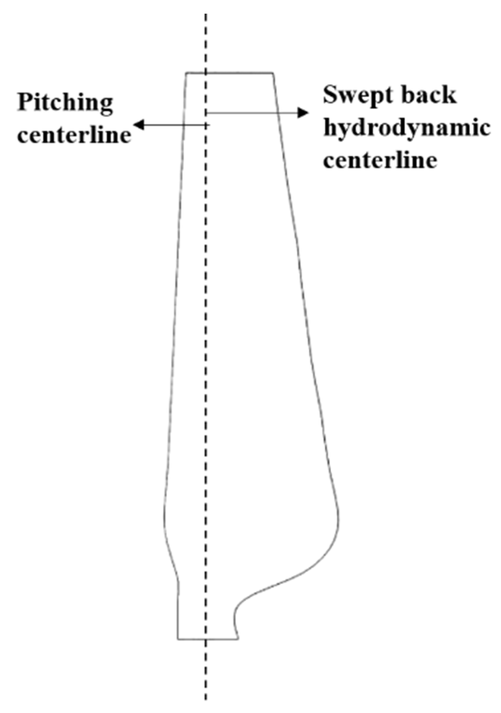
Figure 1. The structure of the initial blade.
Jmse 10 01515 g001
Figure 2. The structure of the backward swept blade.
Jmse 10 01515 g002
Figure 3. The principle of adaptive variable pitch in bidirectional flow.
Jmse 10 01515 g003
Figure 4. The parameters of the backward swept blade.
Jmse 10 01515 g004
Figure 5. Offset comparison of different models.
Jmse 10 01515 g005
Figure 6. Different swept blades 3D model.
Jmse 10 01515 g006
Figure 7. Rotor overall 3D model.
Jmse 10 01515 g007
Figure 8. Grid division of turbine blade surface.
Jmse 10 01515 g008
Figure 9. Grid division of boundary layer.
Jmse 10 01515 g009
Figure 10. Computational domain and boundary conditions.
Jmse 10 01515 g010
Figure 11. Comparison of power coefficients of different models.
Jmse 10 01515 g011
Figure 12. Comparison of trust coefficients of different models.
Jmse 10 01515 g012
Figure 13. Experimental test platform.
Jmse 10 01515 g013
Figure 14. Comparison of experimental data and simulation data of power coefficient.
Jmse 10 01515 g014
Figure 15. Comparison of experimental data and simulation data of the trust coefficient.
Jmse 10 01515 g015
Table 1. Initial blade design geometric parameters.
Spanwise Position (r/R)Radius
r/mm
Chord Length
c/mm
Airfoils
0.0914.94
0.1524.90circle with radius 10
0.2033.2033.44NACA0030
0.2744.8245.54NACA0018
0.3558.1043.51NACA0018
0.4066.4041.49NACA0015
0.4778.0239.46NACA0015
0.5387.9837.44NACA0015
0.6099.6035.42NACA0015
0.66109.5633.39NACA0015
0.73121.1831.37NACA0012
0.79131.1429.34NACA0012
0.86142.7627.32NACA0012
0.93154.3825.30NACA0012
1166.0023.32NACA0012
Table 2. Sweep offset equations for three models.
Model TypeOffset Equation
1 z o f f s e t   =   r r     r s t a r t R   ×   P s / R     r s t a r t M 1     P r 1     P r s t a r t / P r
(Kaya 2018)
2 z o f f s e t   =   a r r R   +   b r r R 2
(Hansen 2011)
3 z o f f s e t = d r r     r start R     r start γ
(Larwood 2014)
Table 3. Offsets corresponding to different models.
Spanwise Position (r/R)Offset/mm
Model 1Model 2Model 3
0.09000
0.15000
0.20000
0.27000
0.3500.001000
0.400.6496220.508800.0982
0.471.8433851.432800.5657
0.533.0828262.422801.2729
0.604.7281193.808802.4556
0.666.2770705.194703.7757
0.738.2149977.042605.6734
0.799.9685968.824407.6065
0.8612.1035211.134210.2193
0.9314.3184113.692713.2171
116.6000016.600016.6000
Table 4. Grid independence verification.
SchemeNumber of NodesTotal Number of GridsPower Coefficient
1497,1982,068,0950.2527
2659,9073,060,7270.2537
3889,3144,972,2070.2486
41,000,1415,035,2950.2898
51,639,7277,848,8630.2899
Table 5. The starting torques corresponding to the three models at different flow velocities.
Velocity(m/s)Starting Torque/N.m
Model 1Model 2Model 3
0.20.00558510.0056708 (+1.53%)0.0055949 (+0.18%)
0.30.01262930.0126649 (+0.28%)0.0126492 (+0.16%)
0.40.02254410.0226049 (+0.27%)0.0225837 (+0.18%)
0.50.03535020.0354231 (+0.21%)0.0354115 (+0.17%)
Table 6. Power coefficients of three models under different TSR.
TSRPower Coefficient
Model 1Model 2Model 3
20.054980.05424 (−1.35%)0.05341 (−2.86%)
30.162360.15923 (−1.93%)0.16284 (+0.3%)
40.25270.25514 (+0.96%)0.25534 (+1.00%)
50.218380.22091 (+1.20%)0.22151 (+1.40%)
60.103930.10739 (+3.22%)0.1096 (+5.17%)
Table 7. Trust coefficients of three models under different TSR.
TSRThrust Coefficient
Model 1Model 2Model 3
20.434410.43453 (+0.03%)0.43299 (−0.33%)
30.644840.63774 (−1.1%)0.64689 (+0.32%)
40.732390.73574 (+0.457%)0.73575 (+0.459%)
50.752270.75575 (+0.46%)0.75702 (+0.63%)
60.728290.73242 (+0.57%)0.73610 (+1.07%)
70.683590.69225 (+1.27%)0.69507 (+1.68%)
Publisher’s Note: MDPI stays neutral with regard to jurisdictional claims in published maps and institutional affiliations.