1. Introduction
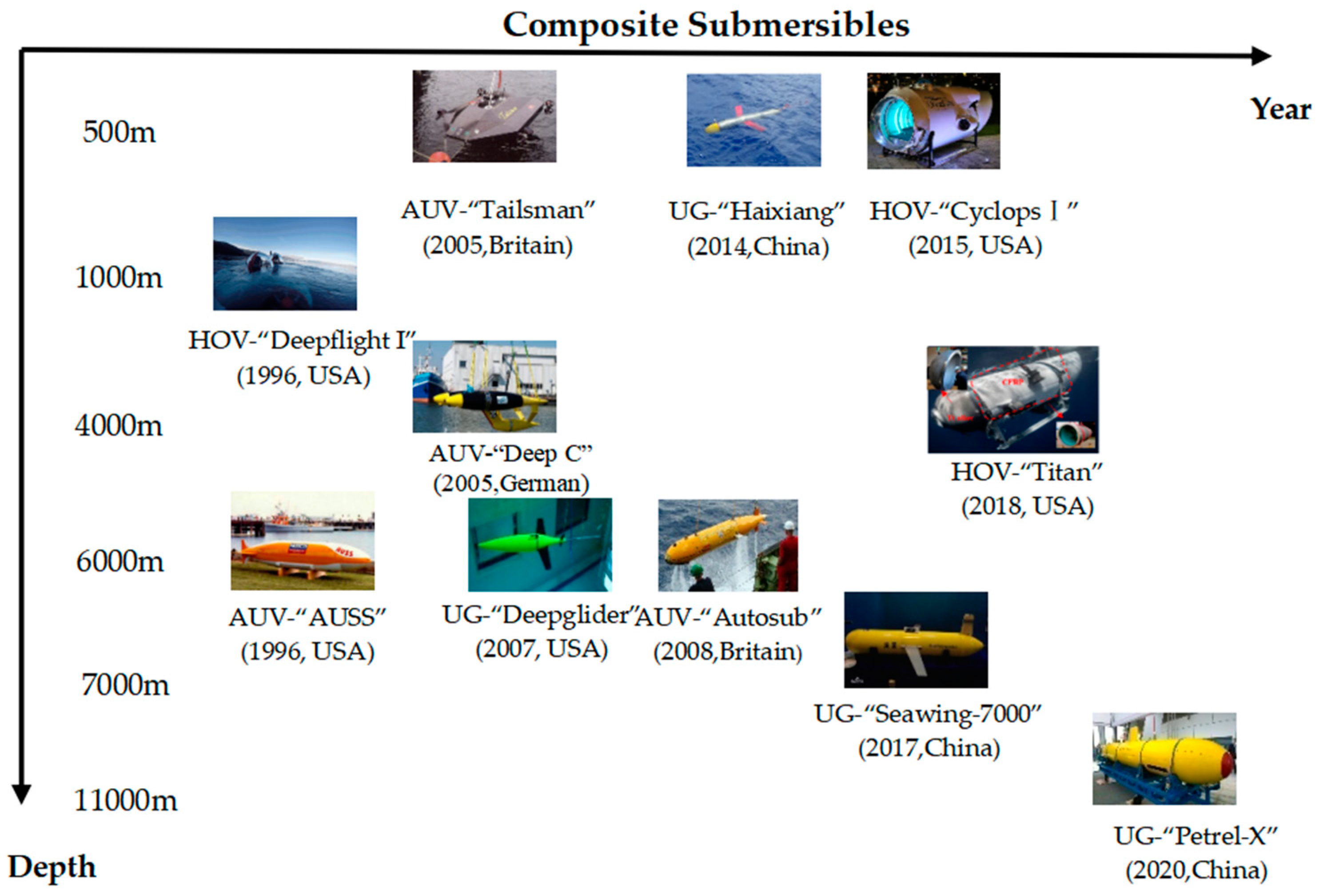
In recent years, the research frontier of equipment technology has developed rapidly in the deep sea field. Various types of high-tech deep-sea equipment have been widely used in marine scientific research, resource exploration, military security and other fields. The composite pressure hull of a submersible is the main provider of buoyancy, and its weight accounts for about 1/4~1/2 of the total weight of the underwater vehicle. Perhaps the most critical consideration for the pressure hull of a submersible is the weight to displacement ratio. The structural material of a pressure hull is one of the main factors that determines its weight-displacement ratio and structural bearing capacity, which is also related to the progressiveness and reliability of submersibles. High strength steel is the most widely used material in general submersibles, and in recent years, titanium alloys with higher specific strength have been gradually adopted. However, deep submersibles have higher material requirements for specific strength and stiffness. Considering all the factors, fiber reinforced polymer (FRP) has greater advantages. In addition to high specific strength and specific stiffness characteristics, composite materials also have a comprehensive range of properties such as the excellent designability, seawater corrosion resistance, acoustic stealth and fatigue resistance. Therefore, composite materials are ideal structural materials for deep sea pressure hulls, and have been widely studied by scholars [
1,
2,
3,
4,
5]. They have been used in deep-sea submersibles worldwide, such as Autonomous Underwater Vehicles (AUV) [
6,
7], Underwater Glider (UG) [
8,
9,
10,
11] and Human Occupied Vehicle (HOV) [
12,
13,
14]; see
Figure 1. Composite materials also have great potential in marine equipment, such as composite pipelines [
15,
16], composite pressure vessels for submarine external stowage [
17,
18]. Composite materials have advantages in improving vibration damping, vibration decoupling and anechoic characteristics [
19,
20], especially the Glass Fiber Reinforced Polymer (GFRP), which has the characteristics of reducing magnetic and electrical signals [
21,
22].
However, due to the particularity of the deep sea environment and the complexity of the composite material, composite pressure hulls will have more complex damage mechanisms than the traditional metal counterparts. For a long time, the mechanical behavior and structural safety of composites in the marine environment have been of wide concern and deeply studied by researchers worldwide. The traditional buckling research system for composite pressure hulls is relatively mature, but it is more suitable for shallow water where the overall buckling resistance design of thin-walled composite pressure structures is dominant. With the increase of the diving depth of the submersibles and the thickness of the composite pressure hull, the structural failure of the pressure hull may change from the overall buckling to gradual material failure. As a result, the design concept of the structure has to be changed. In addition, the large thickness composite pressure hull used in the very deep sea also has its unique failure mode, snap buckling. This problem appeared in the application of deep sea pressure pipelines in the 1980s, and has received more attention and research since then. Therefore, the research on the structural failure mechanism of the large-scale and thick composite pressure hull is an important scientific issue, which needs to be considered not only at the preliminary design stage, but also during the whole service cycle of composite pressure hulls. This paper reviews the structural failure of composite pressure hulls mainly from three aspects, including the overall buckling, materials failure and snap buckling. Based on the research status in China and elsewhere, further problems to be solved for structural failure of composite pressure shells for deep sea application are discussed, which may provide a reference for the study of the mechanical behavior of the composite pressure hull with large scale and thickness, as well as the design and application of actual deep sea equipment.
2. Overall Buckling Failure
At present, cylindrical constructions are the main forms studied in composite pressure hulls, which can be divided into three categories: unstiffened (simple), stiffened and sandwich shells [
23,
24]. In shallow water, stiffeners are often adopted to enhance circumferential flexural rigidity of a cylindrical shell, and hence increase buckling strength as well as achieving an efficient design. Smith [
25] also proposed composite sandwich construction as an alternative form instead of a stiffened cylindrical pressure hull. Because of the thick but low density core and the relatively thin but stiff skins, the composite sandwich shell has a much higher specific stiffness and specific strength, so it can well meet both the overall yield failure and buckling failure criteria of the pressure hull, as well as reducing the heat conduction along the shell thickness, improving the structural strength when the temperature rises, and even providing a stealth function for marine equipment.
Similar to the metal pressure shells, thin-walled or long composite shells mainly produce buckling failure under hydrostatic pressure, and buckling becomes the main failure mechanism. The theoretical and experimental research on buckling failure of composite pressure shells under hydrostatic pressure has been very active in recent years, and most of the research relates to cylindrical shells or circular tubes. Ross and Little [
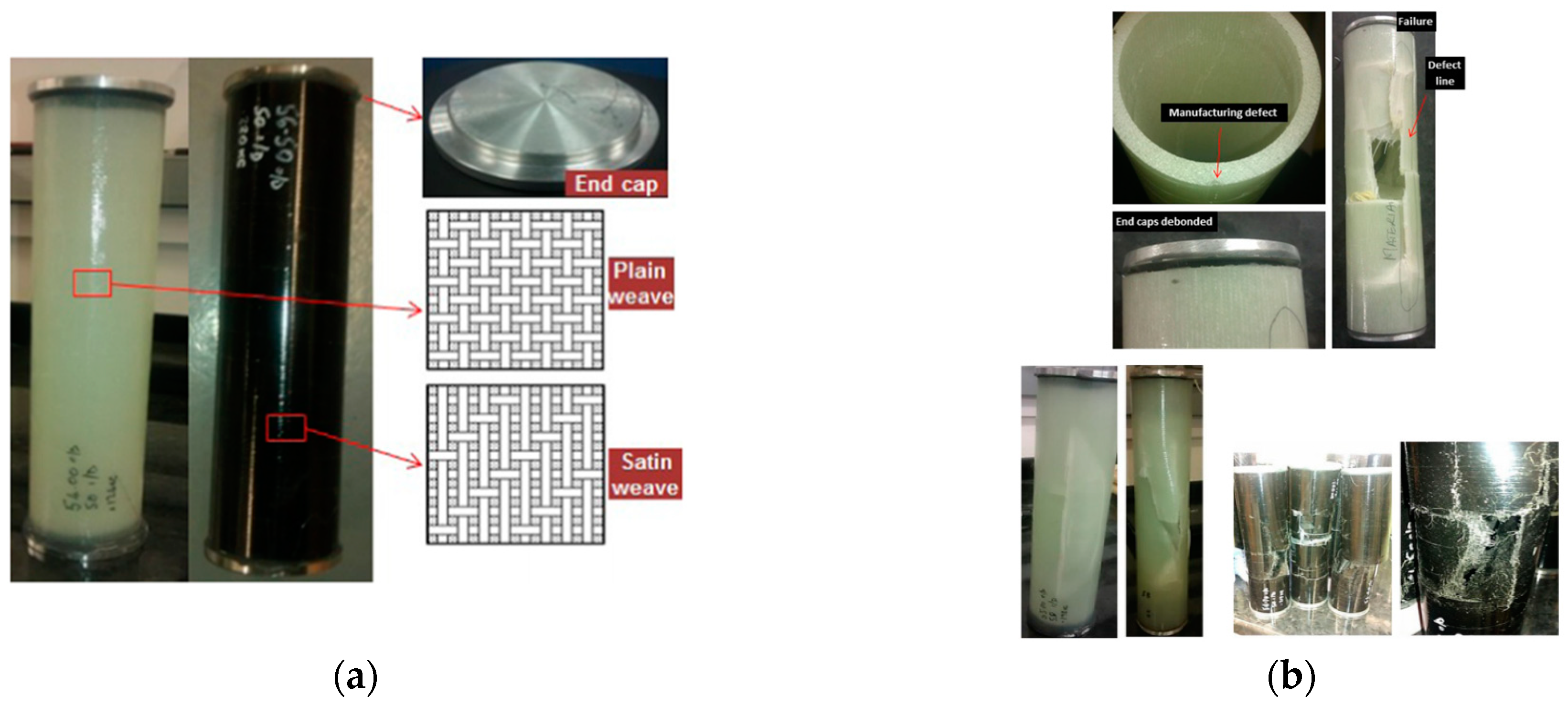
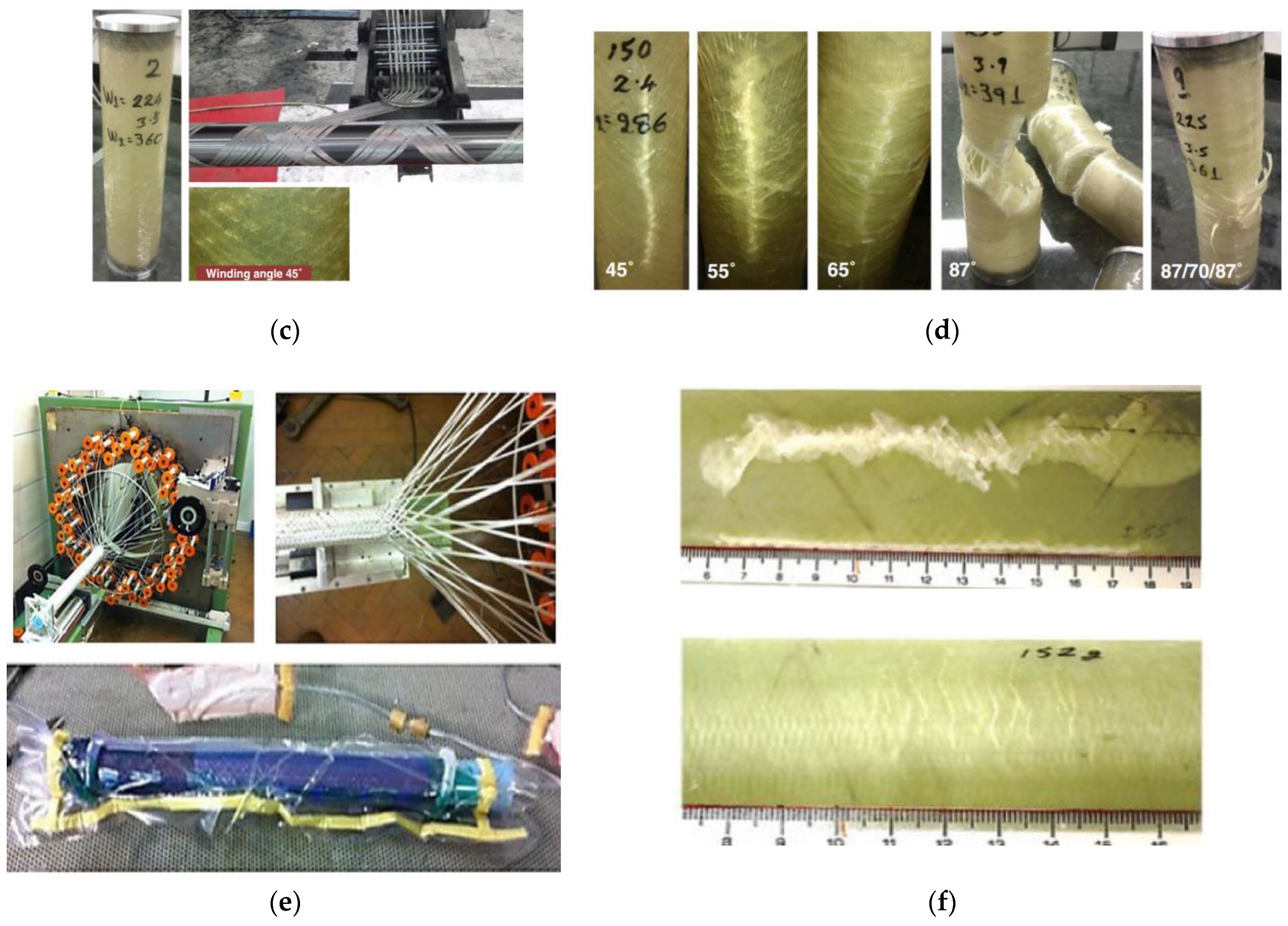
26] tested and analyzed the failure mode of 44 composite circular tubes under hydrostatic external pressure, which were made from a mixture of three carbon and two E-glass fiber layers. Three failure modes were observed including the elastic buckling, inelastic buckling and axisymmetric ‘yield’ failure. Pavlopoulou and Roy [
27] took E-glass fiber as raw material and used three different manufacturing processes, namely laminated prepreg, filament wound and braided process to prepare composite circular tube models. Then, all the composite tubes prepared by different processes were tested to failure under hydrostatic pressure. Typical overall buckling failure modes are shown in
Figure 2. Zhang, Li and others [
28] carried out experiments on three composite cylindrical shells with different stacking sequences under hydrostatic pressure; overall buckling failure occurred in all three specimens, and from the experiment they found that from buckling to final failure, the process was very short.
Based on these failure modes observed in the experiments, the current research on buckling failure of composite pressure shells is mainly divided into two categories, that are the elastic buckling and nonlinear buckling.
2.1. Elastic Buckling
Elastic buckling, also known as linear buckling, is based on linear assumptions. The purpose of linear buckling analysis is to determine critical buckling load, which has been widely used in engineering. Moreover, the results of linear buckling analysis are the basis of nonlinear buckling. Therefore, researchers have carried out many studies on elastic buckling, theoretically and numerically, respectively.
In the theoretical approach, the buckling formula has been established to solve the linear buckling load of composite cylindrical shells, which provides a scientific, reasonable and efficient approach for studying the buckling failure mechanism of composite shells. The buckling problem of the cylindrical shell under hydrostatic pressure (combining lateral and axial pressure) can be solved analytically, when the both ends are simply supported. In the work of Messager et al. [
29], Carvelli et al. [
30], Hur et al. [
31], Hernandez Moreno et al. [
32], and Moon et al. [
33], there were analytical calculation results of the critical buckling load of the composite cylindrical shell under external pressure. Paul and Vasudevan [
34] reviewed the latest research status of stress analysis, buckling and post buckling responses of composite shells under mechanical and thermal loads, focusing on the buckling and post buckling responses of cylindrical shells and conical shells under mechanical and thermal loads and their behaviors under buckling and post buckling conditions. The review showed that hydrostatic pressure, axial pressure and thermal environment had significant effects on the buckling behavior of laminated composite shells. Kardomateas [
35] proposed the benchmark solution of the buckling problem of orthotropic cylindrical shells based on the three-dimensional elastic theory, and pointed out that the classical laminated shell theory is generally highly non conservative in predicting the critical load of thick-walled composite shells. Kasagi and Sridharan [
36] proposed an analysis method of laminated composite thick shells based on three-dimensional nonlinear elastic mechanics, which provides an accurate and effective calculation method for the analysis of thick-walled composite pressure shells under hydrostatic pressure. At the same time, based on p-type finite element, they analyzed the buckling and post buckling responses of laminated thick shells under hydrostatic pressure by axisymmetric solid element calculation processes, and especially studied the interlaminar stress assessment of thick shells in the range after buckling. Gohari and Golshan [
37] used numerical simulation and analytical methods to analyze the first layer failure of thick-walled GFRP cylindrical shells under external pressure, and studied the critical external pressure to avoid the failure of laminated shells by applying various phenomenon failure criteria. Liu and Xu [
38], respectively, used the first-order shear deformation theory and Reddy’s higher-order shear theory to solve linear and geometrically nonlinear instability loads of composite cylindrical shells considering the influence of lateral shear deformation; they obtained the influence curves of geometric parameters, number of layers, layer angle, radius-to-thickness ratio of the shell on the critical load of instability, and revealed the influence mechanism of key shell parameters on buckling failure of the composite pressure shell. Lopatin and Morozov [
39] further considered the torsional stiffness of the end flange of the composite cylindrical shell, used Fourier decomposition and Galerkin methods to analytically solve the buckling problem of the composite cylindrical shell with rigid end plate under hydrostatic pressure, and derived the calculation formula of the critical buckling load of the orthotropic cylindrical shell under hydrostatic pressure. By comparison with the results of finite element analysis, the correctness of the analytical solution was verified, and the computational efficiency of the analytical solution in the optimization design of the buckling resistance of composite pressure shell is verified by typical examples. Li and Guedes Soares et al. [
40] presented buckling solutions for composite laminated cylindrical shells in the underwater environment, and the influences of the geometrical imperfections generated from the process were considered by correcting the stiffness coefficients of the proposed analytical mode, which were validated by finite element analysis.
In numerical research, the finite element method is undoubtedly the most popular method to deal with various buckling and post buckling behaviors of different stiffened shell structures. Numerical simulation and extensive parameter analysis can provide a reference for structural design and optimization. In particular, the finite element method can be used to understand important local effects that are difficult to measure in experiments [
41]. Using commercial finite element software packages such as ABAQUS, ADINA, ANSYS, DYNA and NASTRAN, the buckling behavior of composite pressure shells can be well simulated and solved. Joung et al. [
42] designed an Unmanned Underwater Vehicle using the CFRP/GFRP, and used the ANSYS, MSC and other finite element software to establish the external pressure test model of composite cylindrical shell structure to verify the test results. Ng, Yousefpour and others [
43] used E-glass fiber fabric/epoxy resin composite material to prepare an AUV model prototype, carried out real pressure tests at sea, and compared the findings with the numerical analysis results. Kim and Chao [
44] studied the effectiveness of the finite element method for buckling analysis of wound composite cylinders under external static pressure, and proposed two methods for analyzing the buckling characteristics of thick-walled wound composite cylindrical shells under hydrostatic pressure: one is to use the equivalent performance of composite materials and the other is to use the layer analysis method. They verified the correctness of the finite element analysis by the hydrostatic pressure test, and difference between the finite element calculation results and the test results is about 1~5%. Pandey [
45] used FEM to study the buckling characteristics of the medium-thick-walled wound reinforced carbon fiber/epoxy composite pressure shell under external pressure, and compared it with the buckling characteristics of the unreinforced composite pressure shell. The results showed that the failure pressure of the reinforced composite cylindrical shell was much higher than the unreinforced one, and the buckling pressure of the cylindrical shell with the winding angle of [±60°/90°] was the largest. Jung et al. [
46] selected several groups of different winding angles, such as [±30°/90°]
FW, [±45°/90°]
FW and [±60°/90°]
FW, to conduct finite element analysis and comparative analysis of buckling criteria for the buckling characteristics of wound composite cylindrical shells under external hydrostatic pressure. It was found that the buckling pressure calculated by the ASME 2007 formula had the highest safety factor compared with the test value, and the finite element results were in good agreement with the test value.
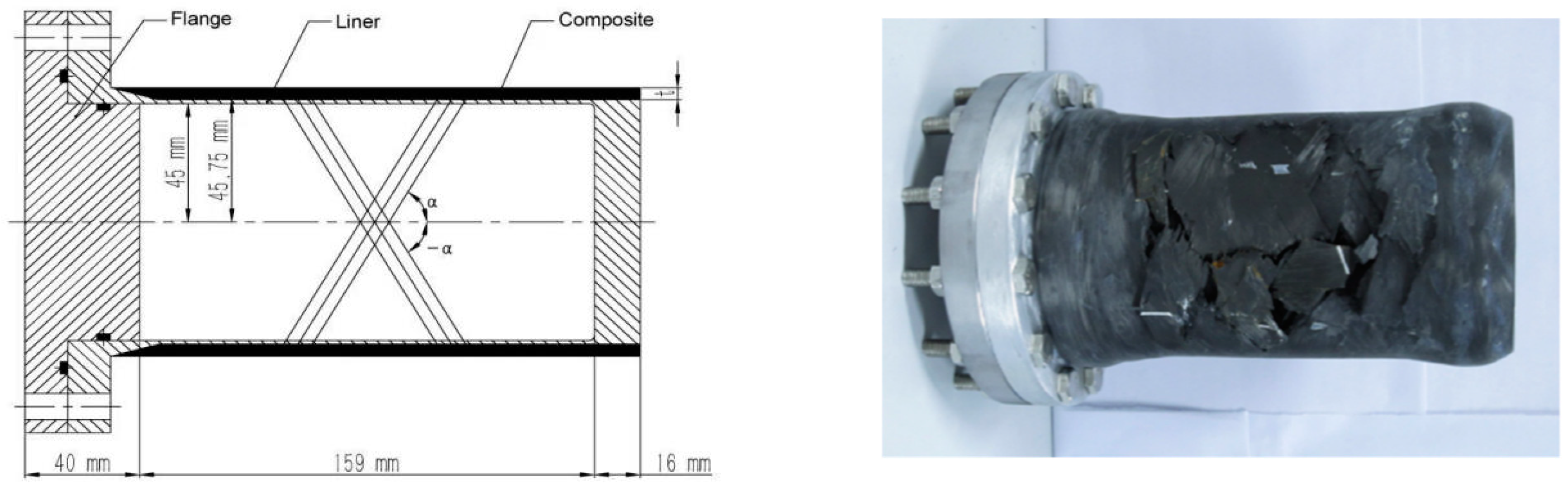
The above researches were mainly aimed at the simple composite shell without reinforcement under hydrostatic pressure. However, in recent years, composite shell with a thin-walled metal liner has been concerned by some researchers. This structural form has been widely used in the fields of aerospace, petrochemical and mobile vehicles due to its light weight, high strength and characteristics of leakage before explosion. However, due to the different load environment, this structural failure research is not sufficient in the underwater area. Cai et al. [
47] carried out the hydrostatic failure test of carbon fiber composite cylindrical shell with aluminum liner. The total thickness-to-diameter ratio of the hybrid shell was 0.0322, with a 3 mm thick composite layer and a 0.75mm aluminum liner, respectively. The shell was crushed just after an overall buckling of the shell in the hydrostatic pressure test, as shown in
Figure 3. It is indicated that using the liner may have some reinforcement effect compared to the pure composite shell. Sumana et al. [
48] conducted an experimental and numerical comparative study on the buckling of composite cylindrical shells with aluminum liner under external pressure, and found that the cylindrical shells with winding angle of 0°/90° have higher buckling strength and lower buckling deformation than those with winding angle of 60°/30°, ±45° and ±55°. Zuo, Zhang and others [
49] carried out a comparative study on steel and steel–composite cylinders under external pressure; three nominally identical steel-composite cylinders and three nominally identical steel ones were tested under uniform external pressure. The total thickness-to-diameter ratio of the steel-composite and steel cylinders was 0.017 and 0.0094. Overall buckling failure occurred in all six specimens, and ultimate load capacity results showed that the steel cylinders could be considerably strengthened by wrapping composite materials.
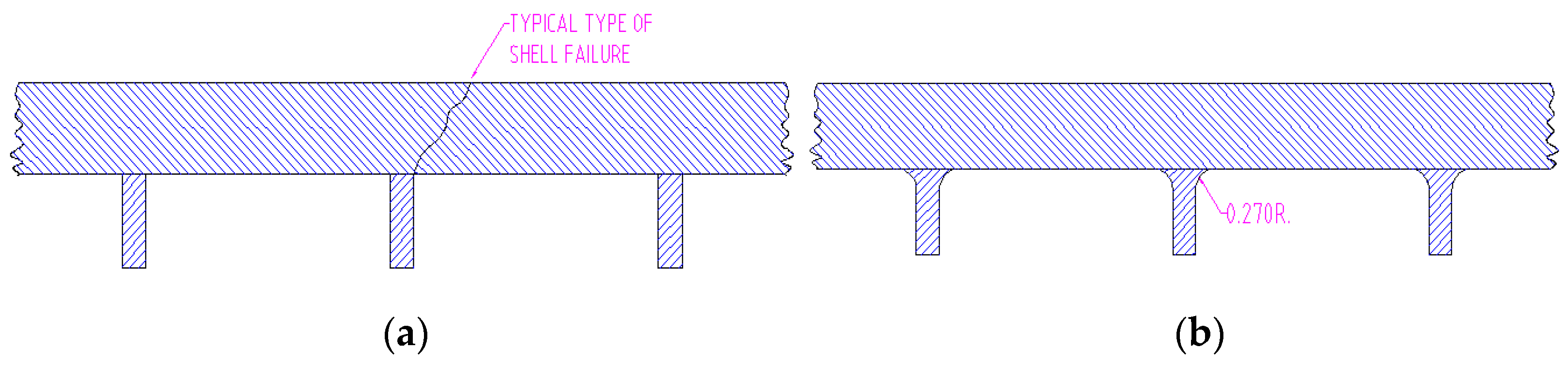
Stiffeners are one of the ways to improve the buckling resistance of composite cylindrical shells. However, if the stiffeners themselves are not strong enough, the stiffened composite pressure shell will produce overall buckling failure. When the composite shell is reinforced by the ring-stiffening, the discontinuity of the structure at the interface between the shell and the stiffeners will cause large local shear and bending stresses. Due to the weak interlaminar performance of the fiber composite structure, the composite shell is destroyed at a lower strength level, and the main failure mechanism is attributed to the shear force. The report of Hom and Couch [
24] studied the problems caused by the buckling resistance design of the ring-stiffened cylindrical pressure shell structure of an underwater vehicle. The research pointed out that when the GRP cylinder was strengthened by the ring frame, the shear crack appeared at the junction of the frame and the shell due to the local bending and shear stress caused by the ring frame, as shown in
Figure 4a, resulting in the failure of the pressure shell at a lower strength level. The structure is improved by setting arc transition between the frame and the shell, and the buckling pressure of the shell is increased by 32%. To study the behavior of externally pressurized elliptical steel cylinders stiffened with helical composite stripes, Zuo, Zhang and others [
50] carried out a hydrostatic experiment on three nominally identical elliptical steel–composite cylinders together with elliptical steel ones. Test results indicated that the collapse mode of the hybrid structure was similar to the typical characteristic of a shell of revolution under uniform external pressure.
2.2. Nonlinear Buckling
In practice, instability is a typical nonlinear behavior. Nonlinear buckling can occur on structures without defects, mainly due to large deformation caused by structural buckling, resulting in geometric nonlinearity. In addition, some material nonlinearities and/or boundary nonlinearities may be experienced, so it is generally recommended to perform nonlinear effect simulation step by step. Krasovsky, Marchenko and others [
51] conducted geometric nonlinear finite element modeling and research on buckling analysis of stiffened cylindrical shells under axial compression and external local loads. Pan, Lu and others [
52,
53,
54] studied the nonlinear buckling behavior of composite cylindrical pressure shells, and analyzed the buckling behavior of composite cylindrical shells with different rib forms under hydrostatic pressure.
Actually, the composite pressure shells are not always ideal perfect shells, and defects may occur in the process of manufacturing, storage, transportation, installation and use. It is generally considered that an initial geometric defect is the main reason for the reduction of the buckling load of the shell. The geometric defect can be an overall shape defect, such as the elliptization of the circular shell and the deviation of the shell axis from the straight line, or a local geometric defect, that is, the deviation from the nominal geometric value, called as the thickness change. For the composite shell, in addition to the geometric defects, the defects generated in the manufacturing process of the material should also be considered, such as delamination defects unique to the composite, the pores in the composite, the fiber misalignment and the deviation from the theoretical layering sequence. The occurrence of defects has an important impact on the buckling and failure of the shell. In order to quantify the influence of defects on the ultimate load of shell, the concept of “defect sensitivity” is introduced. The defect sensitivity is measured by the Knockdown Factors (KDF), which is the ratio of the critical buckling load of the shell with defects to the nonlinear buckling critical load of the ideal perfect shell. The buckling critical load of the ideal shell obtained by theoretical calculation is sometimes 50% higher than that obtained by experiment because the influence of defects is not considered.
One of the important contents of the early shell buckling research is to explain the huge gap between the classical theory and the experimental measurement, and it is aimed at the cylindrical shell under axial compression. The study on the stability of cylindrical shells under external pressure is much later than that under axial pressure. The earliest work was carried out by Von Mises and Flugge. Simitses and Kardomates [
55] studied the instability problem of composite cylindrical shells with defects in medium thickness under uniform transverse pressure, and considered that the range of defect sensitivity of composite shells largely depends on the anisotropy of materials, the thickness of shells and whether the influence of end loading pressure is included. Shen, Jiang and others [
56] studied the buckling characteristics of a thin-walled composite cylindrical pressure shell with defects under hydrostatic pressure, and considered the influence of geometric defects caused by the winding process on the buckling load of a composite pressure shell. The results show that the existence of geometric defects leads to the sharp reduction of the buckling load of the composite pressure shell. Tsouvalis, Zafeiratou and others [
57,
58] proposed a method of introducing geometric defects into the finite element model of composite cylindrical shells. The accuracy of the method was verified by comparing the calculation results with the experimental ones. Through the parametric model, the influence of the initial defect amount and the end boundary conditions on the buckling load of composite cylindrical shells under external hydrostatic pressure was studied. It was found that the buckling ultimate load of cylindrical shells decreased with the increase of the geometric defect amplitude. The actual buckling load of the shell is 24~40% lower than that of the intact shell, and the influence of geometric defects on the critical buckling load grows with the rise of the end support stiffness. Sun [
59] studied the influence of geometric defects on the bearing capacity of composite cylindrical shells with initial defects under external pressure by using the single point perturbation load method, the least favorable point perturbation load method, the eigenvalue buckling mode defect method and the measured defects method, and obtained the corresponding effects of single point hollow defects, multi-point hollow defects, eigenvalue buckling mode defects and the measured defects on the bearing capacity of composite cylindrical shells. Jiang [
60] studied the influence of circumferential, axial and rectangular delamination on the critical load of laminated cylindrical shells under axial and external pressure. Li, Liu and others [
61] considered the nonlinear pre buckling deformation and initial geometric defects of the shells in the post buckling analysis of the medium thickness and thick anisotropic laminated cylindrical shells under the combined action of external pressure and axial compression, and extended the boundary layer buckling theory of laminated cylindrical shells. Błachut [
62] considered geometric shapes including hemispherical, ellipsoidal and elliptical shapes in the buckling research of composite heads with local defects under external pressure. They mainly studied the nonlinear buckling characteristics of composite heads with concave defects based on Force-Induced-Dimple method and nonlinear finite element method. Zhang, Li and others [
63] studied the buckling problems of composite shells with initial imperfections under hydrostatic pressure; a novel initial imperfection model was introduced to study the effects of initial imperfection parameters and ply angle as well as stacking sequence on the critical buckling pressures of composite shells. Wei, Shen and others [
64] numerically investigated the delamination damage and the effect of buckling behavior on delamination propagation in the composite cylindrical shell subjected to hydrostatic pressure. It was found that local or global buckling of the shell promoted the propagation of delamination, and the ultimate buckling pressure of the shell was more sensitive to the axial initial delamination length.
In a word, scholars in China and elsewhere have carried out extensive research work on buckling failure of composite pressure shells under hydrostatic pressure. Most of them focused on thin shells with relatively small thickness to radius ratio. For thick composite pressure shells, there was still a lack of effective theoretical methods to predict critical buckling loads. The effects of shell defects formed by different processes, composite layer structure and thickness ratio on shell nonlinear buckling require further study.
3. Material Failure
In addition to structural stability, the factor of material failure of the pressure hull cannot be ignored. In some cases, especially for thick wall composite shells, the loss of bearing capacity was caused by material failure under compression. Under hydrostatic pressure, uniform compressive stress was mainly generated in the composite shell. However, the compression strength of the composite material was not only related to the placement of the shell, but also to the coupling relationship of tension-bending and tension-shear in the constitutive relationship of the material, making the failure analysis and strength prediction of the composite structure much more complicated.
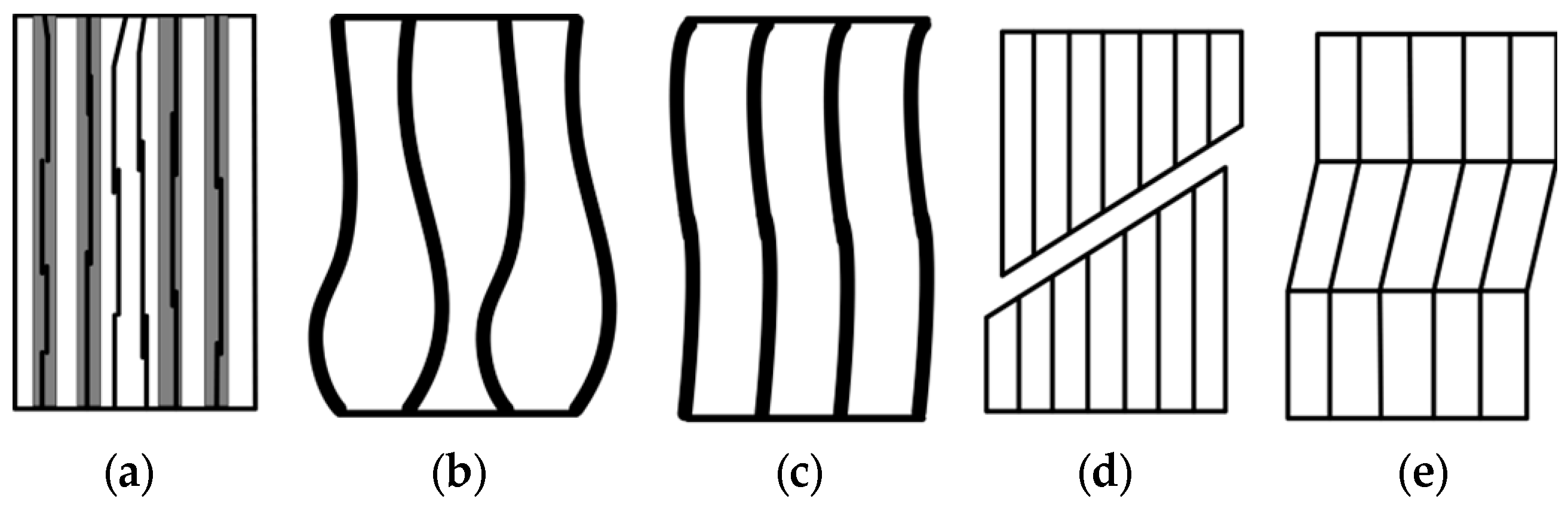
However, at present, the compression failure research of fiber composites has mainly focused on the composite structure under axial compression, while the combined load of axial and lateral pressure was less studied. When composite structure is subjected to unidirectional compressive load along the fiber direction, the continuous fiber acts like an elongated column, and the fiber would buckle. Even if the volume content of the composite fiber is very low, and even when the matrix stress is within the elastic range, the fiber microbuckling will also occur. Fiber buckling failure and microbuckling failure are the most important failure modes of composite materials under axial compression. The main failure mechanisms are as follows [
65,
66,
67,
68]: (i) If the strength and toughness of the matrix are relatively weak compared with the fiber, the internal fracture of the matrix will occur under the action of compressive load. Macroscopically, the failure mode is longitudinal splitting of the substrate through the plate thickness parallel to the fiber direction (
Figure 5a). (ii) If the matrix has higher toughness and strength than the fiber, and the interface between the fiber and the matrix is not well bonded, the material will produce delamination defects and wear damage under the action of compressive load. Macroscopically, the main failure mode under longitudinal compression load is shear failure (
Figure 5d). (iii) If the toughness and strength of the matrix are higher than that of the fiber, that is, when the interface between fiber and matrix is well combined, the specimen will bend under compressive load, leading to shear instability. The section and the loading direction are about 45°, which shows that the fiber is crushed macroscopically (
Figure 5e). Fiber microbuckling usually occurs after matrix yield, component degumping and matrix microcracking, which is manifested as follows: when the fiber volume fraction is small (V
f < 0.2), the fiber will buckle in the reverse direction, and the strain in the matrix will be either tensile or compressive, which is the tension-compression mode (
Figure 5b). However, at the actual fiber volume fraction (V
f > 0.2), the fiber buckles in the same direction, which is the shear mode (
Figure 5c).
The failure modes of composites under compression are mainly affected by four factors: material properties, fiber deflection angle (the angle between longitudinal direction of the fiber and loading direction), fiber volume content, and defect sensitivity. An effective technical approach to improve the compressive bearing capacity of a composite materials is to improve the shear modulus, shear strength, fiber volume content, and to reduce the fiber deflection angle and its own defects [
69].
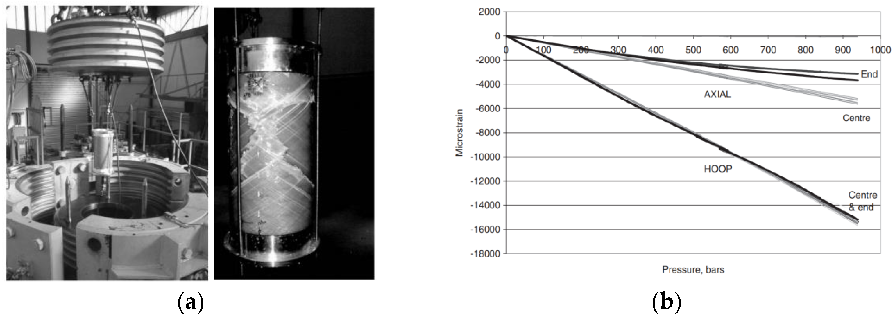
Under hydrostatic pressure, the composite shell needs to bear bi-axial compressive load, and the failure modes are very complex. The researches on its bearing capacity and failure mode have been mainly based on experimental research. As part of the research work of The World Wide Failure Exercise, Soden et al. systematically gave The Failure test results of thick wall fiber composite circular tubes under biaxial compressive load (lateral and axial pressure) [
70,
71]. It has important reference significance for understanding the compression failure mechanism of composite materials under hydrostatic pressure. The results show that all thick-walled composite tubes fail due to rupture rather than buckling.
Figure 6 is the shell strain diagram of E-glass fiber/epoxy composite circular tube with winding angle of 55° under biaxial compressive load.
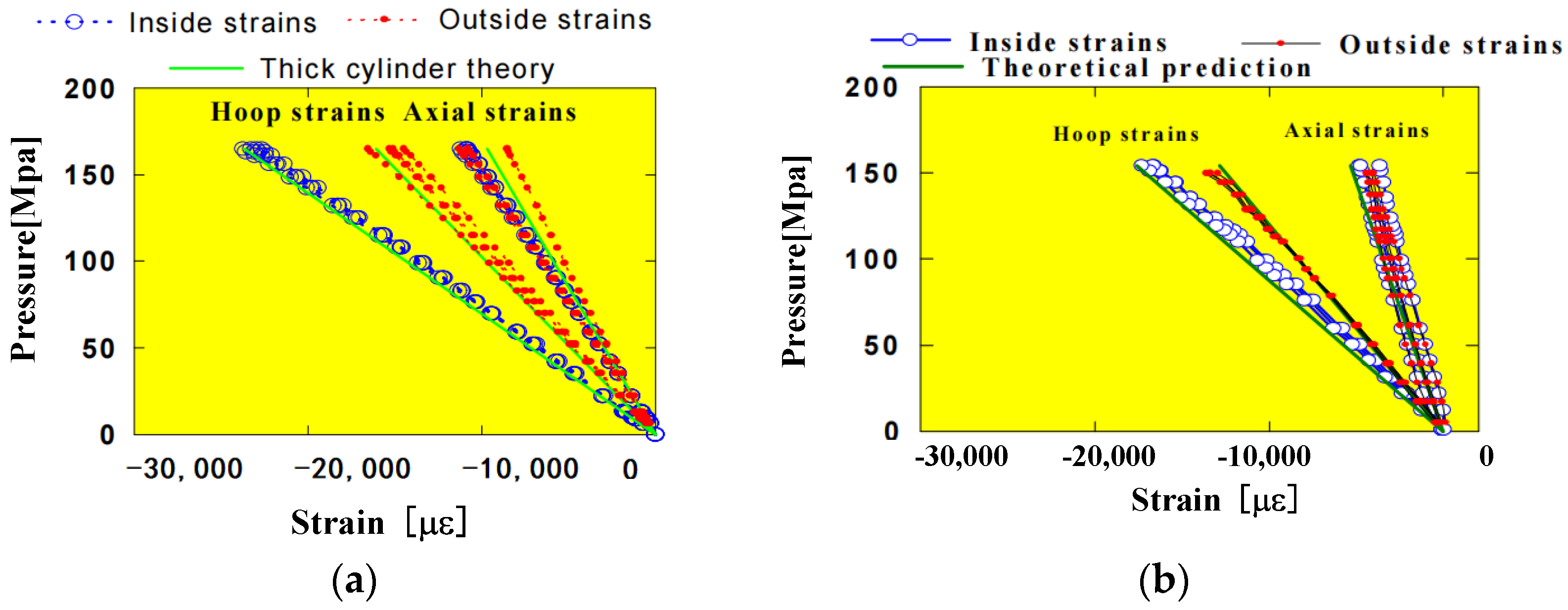
Davies, Riou and others [
72] conducted a comparative study on the mechanical behaviors of glass-fiber and carbon-fiber reinforced epoxy composite thick-walled cylindrical shells under hydrostatic pressure. The diameter and thickness of specimen were 175 mm and 20 mm, respectively. Eventually the specimen was failed at about 90 MPa. The failure mode, hoop and axial strains of the shells are shown in
Figure 7 and
Figure 8. For thick glass fiber/epoxy and carbon fiber/epoxy composite cylindrical shells, strain gauges detected no signs of buckling.
The main theoretical prediction methods for composite material performance subjected to compressive load include elastic microbuckling theory, nonlinear microbuckling theory, three-parameters model, fracture mechanics method, finite element analysis method and cumulative damage analysis technology [
73,
74]. Among them, the first three methods mainly predict the compressive strength of unidirectional composite material under compression failure. The last three methods can be used to predict the compression failure of composite shell structures. At present, the possible strength failure factors of the pressure shell are considered in the failure research and performance optimization of some deep sea composite pressure shells, and the method based on First Ply Failure is adopted, that is, the failure of any single layer of the composite laminates will result in the overall failure of the entire composite. Carvelli et al. [
29] analyzed the shell strength under buckling failure and material compression failure modes, respectively, for the glass fiber composite cylindrical thin shell with an external diameter of 740 mm, and carried out a real sea test. The Tsai-Hill criterion was used to predict the structure failure or the strength of the shell. The analysis results showed that the buckling strength of the shell was less than the compressive strength of the material, and the final failure was dominated by the overall structural buckling. Tsai–Wu and maximum stress failure criteria were used by Fathallah et al. [
75,
76] to analyze the material strength failure. They minimized the buoyancy coefficient of the composite pressure shell as the objective function, and took the failure strength and buckling strength of the shell as the constraint function to optimize the layup of the composite pressure shell. Shen et al. [
77,
78] predicted shell failure based on the Tsai–Wu failure criterion and established an optimization platform based on genetic algorithm and analytical schemes to optimize the design of filament wound cylindrical shells.
In view of the characteristics of nonlinear material and progressive failure of composite materials, it is necessary to consider the influence of material damage on the strength and stability of composite pressure shells during the pressure bearing process, which can be achieved by establishing a progressive failure model. According to the progressive failure theory, the failure of one layer of composite material does not mean the failure of the whole laminate. After the failure of some elements, the laminate can continue to bear the load, and the failure of the whole laminate is not considered until all the laminates fail. This method is called the Last Ply Failure method. The analysis model based on this method is a progressive failure model, and the corresponding load is named as the ultimate strength.
Graham et al. [
79,
80] carried out a series of tests and analyses for thick-walled composite cylindrical pressure shells in the European composite underwater pressure structure project, and believed that the Hashin criterion was more appropriate for gradual failure analysis of shell strength. Hur et al. [
30] used the maximum stress criterion combined with the complete stiffness degradation model to study the layer failure behavior of the thin-walled composite shell after buckling. Chen and Zhu [
81] consider structures such as initial geometric imperfection and the material nonlinearity and so on, using the algorithm of nonlinear arc length and introduce the Hashin failure criterion and the damage evolution criterion, for the sandwich composite cylindrical shell model, carrying out numerical research on voltage, assessing both structural strength and stability of the double indicator, predicting structure gradual failure mode and ultimate load. The numerical analysis results are in good agreement with the experimental results.
In a word, the microscopic failure mechanism of composite materials under axial compression has been studied in detail. However, the composite materials under hydrostatic pressure are under bidirectional compressive stress, and their damage characteristics and failure mechanism are different from those under axial compression; this needs to be further studied. Some scholars have carried out failure tests of composite thick wall round tubes or cylindrical shells under hydrostatic pressure to obtain the compression failure mode of composite shells, and complex progressive failure processes such as fiber and matrix failure, fiber-matrix in-plane shear damage, and interlayer delamination/debonding of composite shells. The progressive damage failure analysis methods for deep sea thick wall composite pressure shells need further research and improvement.
4. Snap Buckling Failure
Snap buckling is a unique failure mode of composite shell with large thickness under high hydrostatic pressure in the deep sea. Its particularity lies in the fact that delamination buckling can occur without initial delamination under high pressure stress. In this case, buckling is accompanied by instantaneous interlaminar fracture. On the other hand, snap buckling is a nonlinear problem, different from the linear problem in which the post-buckling equilibrium form is close to the pre-buckling equilibrium form. The transition of snap buckling to a new equilibrium state occurs instantaneously, and the new form is essentially different from the original form, as depicted in
Figure 9.
In the 1970s, Kachanov [
82,
83] made a theoretical study on the snap buckling phenomenon in thick-walled fiberglass composite pipe under pressure in the deep sea, and its failure mechanism was as follows: When the external water pressure reached a critical value, the thin sub-layer of the thick-walled composite pipe would be delaminated from the inner surface suddenly and snap buckling would occur; then the interlaminar cracks would propagate rapidly along the interface of the delaminated composite layer, leading to the final failure of the structure. This paper pointed out the necessity and importance of the study of the snap buckling problem. Since the deflection at the center of the delaminated sub-layer was several times the shell thickness, a large deflection theory was needed to solve the critical load of structure.
At present, when considering the delamination buckling problem of a composite shell, delamination was assumed to be already present in most instances, mainly due to manufacturing factors or in service, resulted in the interlaminar fect. For example, Kardomateas and Chung [
84] theoretically analyzed the critical load of the buckled composite cylindrical shell model with an axial through-film delamination. Li and Zhou [
85,
86] established an axial buckling analysis model of laminated cylindrical shells containing circumcircular through-delamination composite materials by using the high-order shear deformation theory. The buckling equation and fixed solution conditions of delamination shells were derived by using the variational principle, and the critical buckling load of delamination shells was obtained by using the state-space method. Tafreshi [
87,
88,
89] used gap element to prevent the mutual penetration of delamination sub-layers after buckling, and applied binding constraints to the nodes in the undelamination zone and the nodes in delamination zone to maintain displacement coordination. The buckling of laminated composite cylindrical shells with rectangular delamination on the surface and axial through-delamination was studied. The critical buckling loads and the influence laws of parameters of composite cylindrical shells with delamination under axial compression, lateral compression and combined loading are obtained. It is proved that neglecting the contact effect of delamination will lead to unreasonable calculation results. Fu and Yang [
90], based on the variational principle of movable boundary and considering the contact effect between delamination, studied delamination extension of composite cylindrical shells with circumferential penetration delamination under external pressure in combination with the Griffith criterion.
However, it should be noted that even if there was no initial delamination in the structure under certain specific loads, delamination will occur in the process of loading due to the lower interlaminar strength, and the generation of delamination and the buckling of delamination sub-layers may occur simultaneously, namely the so-called “delamination coupled buckling”. Kachanov [
91] specifically explained this problem in his work. He divided the delamination buckling of composite materials under external pressure into two categories. One was linear buckling, that is, the equilibrium configuration of the film after delamination buckling was similar to that before buckling, which could be solved by using the theory of linear elastic fracture mechanics. The other was a nonlinear buckling problem, the equilibrium configuration of film delamination changing greatly compared to that before buckling. This snap buckling becomes a nonlinear problem and needed to be solved theoretically by using large deflection theory combined with fracture mechanics method. In either case, the local delamination could be regarded as a crack in the bonding zone of the composite material. With the local buckling deformation of the film delamination, high interlaminar stress was generated at the crack tip, which leads to the propagation of the delamination crack and ultimately to the loss of the overall stability of the structure.
Bottega [
92,
93] regarded the delamination buckling of composite cylindrical shells as a variational problem of movable boundary, established a mathematical model of delamination buckling based on flat shell theory, obtained the buckling control equation and boundary conditions, matching conditions and cross-sectional conditions by energy functional, and carried out numerical analyses on the post-buckling distortion. Based on Griffith energy balance principle, we obtain the delaminating extension path, concluding that due to the existence of contact area, for the delaminating extension in type II fracture pattern or type I and II mixed mode fracture, the process is likely to be stable or unstable, or even disastrous, mainly depending on the size of the delamination and bond strength of structural materials.
Yin [
94] established a model for delamination and jump buckling of thin films on the inner surface of cylindrical shells under axial compression, and deduced a nonlinear difference equation with elliptic integral by using classical elastic line theory, which is suitable for finite deformation and arbitrarily large rotation. The classical laminated shell theory, transverse shear deformation theory and small deflection flat shell theory were used to solve the problem. By comparing the theoretical solutions, it is found that transverse shear deformation causes greater buckling deflection of film delamination, but it has no significant effect on the energy release rate of delamination, while the theoretical solution of flat shell based on small deflection significantly underestimates the strain energy release rate of delamination.
Based on the elastic similarity theory, Wang and Shenoi [
95] established a nonlinear difference equation with elliptic integral, and analyzed the delamination buckling and propagation characteristics of composite laminated curved beams subjected to the closing moment. The derived results could evaluate the critical load and analyze the buckling characteristics of composite rings and long composite cylindrical shells under uniform external pressure.
Recently, Luo and Wang [
96] established a model of delamination and hopping buckling of the inner surface of composite spherical shells under compression based on the principle of elastic similarity. The governing equation of delamination buckling was established by using nonlinear large deflection theory, and the critical load expression of delamination buckling of composite spherical shells was obtained. The coupling buckling characteristics of composite spherical shells without delamination in the initial state were studied, and the effects of delamination thickness, delamination location and delamination size on the critical buckling load were discussed.
In general, snap buckling of large-thickness composite pressure shells under the high pressure of the deep sea had only been studied theoretically, and few experimental and numerical results had been obtained. The possible reason is that at present, it is difficult to directly observe the snap buckling failure mode of composite shells in the test under external load, and the influence of snap buckling on the ultimate bearing capacity of deep sea composite shells could not be quantitatively evaluated. As future composite materials are developed for large scale use, and large depth of latent application of the pressure shell, special attention needs to be paid to shell structure buckling failure as an important security hidden danger. Further research is needed to establish deep big thickness of composite pressure shell buckling failure criterion layer coupling, to guide the design of deep sea pressure shell material resistant to delaminating buckling.
5. Other Failure Modes
With the further recombination of FRP with core or metal materials, new underwater pressure shells, such as composite sandwich shells or composite shells with metal liner, have been investigated. Some new failure modes have emerged besides the above mentioned main failure modes. For the sandwich composite shell, affected by the properties of the composite skin and core material, the sandwich shell may produce complex failure modes such as skin fiber fracture, fiber delamination, local skin shear instability, skin and core material denomination, core material shear instability, and combined failure [
97,
98]. Lee, Kweon and others [
97] carried out hydrostatic external pressure test and calculation verification on the sandwich composite cylindrical shell. The core material of the sandwich shell was Nomex honeycomb, and the skin was carbon fiber prepreg with [0/90]
4s. The sandwich shell was formed by co-bonding process. The failure mode of the sandwich shell obtained during a hydrostatic external pressure test is shown in
Figure 10. The sandwich shell exhibits complex failure modes, such as global buckling and skin fiber fracture, fiber delamination, skin and core interface debonding and combined failure. The design load of the composite sandwich cylindrical shell under external hydrostatic pressure was improved by the optimization method, in which the overall buckling and material failure modes were considered.
Yuan, Bengsima and others [
98] carried out hydrostatic tests on the composite sandwich cylindrical shell, with a low modulus polyurethane core. Overall buckling failure mode was found in the shell, together with an obvious fiber fracture that occurred in both inner and outer skin. Simultaneously, combined failure modes such as delamination between the skin layers and the skin/core interface occurred. In addition, another composite sandwich shell model with a larger modulus of core was manufactured and tested under hydrostatic pressure, by Zhu and Li [
99], to compare their failure modes and mechanical behaviors. It was found that composite sandwich shell with a large Young’s modulus core was crushed, with the composite part of the model split into several parts. It was indicated that material failure of the skin, initiated by the matrix cracking, not overall buckling, dominated the overall failure of the composite sandwich shells, according to the numerical results of the model. Kardomateas, Simitses and others [
100] proposed an elastic solution to the buckling of long composite sandwich cylindrical shells under external pressure load. The results showed that there was a great difference between the three-dimensional elastic theoretical solution and the shell theoretical solution, for the composite sandwich shell, compared with the uniform laminated composite ones. Li, Wu and others [
101] numerically simulated the stability of the composite sandwich shell and the delamination evolution behaviors between the skin and core, under the same load of internal and external pressure by FEM. Liang and Chen et al. [
102] optimized the filament-wound composite sandwich pressure hull for an underwater vehicle. Multiple discrete variables, such as overall buckling failure of the shell, composite skin failure and yield failure of the core, were considered to identify design constraints. The thickness and fiber orientations of the skin, together with the thickness and shear modulus of the core, were chosen as design variables. Using carbon fiber, glass fiber and boron fiber reinforced epoxy resin as composite materials for the skin, respectively, the influence of operating depth, geometric parameters and aspect ratio (L/D) on the performance of the composite pressure shell was studied, which could provide a reference for the design of pressure shell of underwater vehicles.
6. Conclusions and Recommendations
The current study mainly reviews the progress of structural failure of composite pressure hulls in the deep sea from three aspects: overall buckling failure, material failure and snap buckling failure. Overall buckling failure tends to occur for thin or long composite shells for underwater vehicles, which was the main concern of many researchers till now. A large number of theoretical, numerical and experimental results have been obtained, giving a profound understanding of the buckling failure mechanism of composite pressure hulls under external pressure.
However, with the increasing depth of composite submersibles and deep sea pipelines, etc., the pressure shells will become more and more thick, material failure may occur before overall buckling, and it is difficult to directly determine the ultimate strength of the pressure shell, for in some cases only the material failure mode was observed in the hydrostatic test. Correspondingly, progressive damage analysis was adopted as a way to study the influence of material failure on the ultimate bearing capacity of the pressure hull. In addition, material failure may also occur in the post-buckling stage of moderately thick shells, which was a concern of some researchers.
In particular, a unique failure mode that is prone to emerge only in the underwater environment for composite shells, namely so-called snap buckling or delamination coupled buckling failure mode, has already been demonstrated to exist for the very thick GFRP composite pipes used in the deep sea. Unfortunately, however, investigations on this subject have remained at theoretical level. There is still very little research in this area in recent years.
Generally speaking, the current research on the structural failure of composite pressure hulls in the deep sea is still in the exploratory stage. According to the authors, there are still some problems as follows:
- (1)
The composite pressure hull that is suitable for large diving depths is a medium thick or large thick shell; either overall buckling or material failure may occur, or both. However, there are few studies on the relationship between them, and no appropriate criterion has been established to distinguish them.
- (2)
Under hydrostatic pressure, the composite material of the pressure hull withstands a bidirectional compressive stress. Whether the existing progressive damage methods are appropriate to study the effects on a thick composite pressure hull or not, has not been sufficiently investigated.
- (3)
Research on the important snap buckling failureof a large thickness composite pressure shell under high external pressure has been limited to theoretical approaches, while the experiment validation is not sufficient.
- (4)
The nonlinear buckling behavior of thick composite shells under hydrostatic pressure needs to be further studied, to evaluate the effect of various defects on the ultimate bearing capacity of the composite shells.
- (5)
Studies on progressive failure of thick composite pressure shells in the deep sea are still lacking.
Future studies should pay more attention on the structural failure of moderate thick and thick composite pressure shells under hydrostatic pressure, since their bearing capacities may be directly determined by material failure or overall buckling, or by the coupling of them. An efficient method for progressive damage analysis of composite pressure hulls should be established and validated, to predict the ultimate load capacity of the composite pressure hull in a deep sea environment.
Moreover, the structural failure caused by nonlinear buckling should be further studied, since overall buckling is still the main form of failure of composite pressure hulls. The existence of defects is the key factor to determine the collapse load of the shell. Defect introduction methods suitable for study of composite pressure shells need to be developed. The influence of the unique lamination defects, internal pores, fiber misalignment and the deviation from the theoretical layup sequence of composite materials on the ultimate load capacity of pressure shell need to be further investigated.
Finally, great effort should be paid to strengthen research on the snap buckling failure of large-thickness shells under high hydrostatic pressure, not only limited to the theoretical investigation, but also the numerical and experimental aspects. In particular, effective and reliable tests are needed to understand this unique failure mode and the critical buckling load caused by snap buckling, though this is very difficult in practice. This is vital to gain an insight into the snap buckling failure characteristics, and helpful to validate the theoretical and numerical work on this form of failure.


