Article

An Electro-Hydraulic Hitch System Based on Digital Hydraulic Valves with Adaptive Control for High-Horsepower Tractors

1
Key Laboratory of Advanced Transducers and Intelligent Control System, Ministry of Education, Taiyuan University of Technology, Taiyuan 030024, China
2
School of Mechanical Engineering, Taiyuan University of Science and Technology, Taiyuan 030024, China
*
Author to whom correspondence should be addressed.
Agriculture 2026, 16(18), 2020; https://doi.org/10.3390/agriculture16182020 (registering DOI)
Submission received: 18 August 2026 / Revised: 9 September 2026 / Accepted: 17 September 2026 / Published: 20 September 2026

Abstract

Conventional tractor hitch systems employing mechanically controlled multi-way valves suffer from low control precision and sluggish dynamic response, which render them inadequate for field operations characterized by highly variable soil resistance. To address these limitations, this paper proposes an electro-hydraulic hitch control system based on digital hydraulic valves for high-horsepower tractors. The proposed system integrates a load-sensing pump with pressure-compensated proportional valves to achieve supply-demand flow matching for the hitch cylinder, improving the smoothness of implement attitude regulation. Furthermore, an adaptive fuzzy Proportional-Integral-Derivative (PID) control strategy is developed for simultaneous tillage depth and traction force control, enhancing the accuracy of both controlled variables. A tractor simulation model and an experimental test rig are established to evaluate the hitch control performance under various operating modes. Experimental results demonstrate that the proposed digital-valve-based hitch system exhibits favorable control performance. Compared with conventional PID control, the proposed approach improves the depth stability coefficient and the load stability coefficient by 7.5% and 7.4%, respectively, under depth and traction control modes. Under force-position combined control, the depth and load stability coefficients reach 92.1% and 89.1%, respectively, confirming that the proposed method maintains both tillage depth consistency and load regulation effectiveness.

1. Introduction

The tractor three-point electro-hydraulic hitch system is a key actuation system for implement attachment, lifting/lowering, attitude adjustment, and working-depth regulation. Its dynamic response characteristics and control precision directly affect the operational quality and traction performance of the tractor [1,2]. In recent years, with the rapid development of smart agriculture technologies, tractor operations have been progressively evolving towards intelligent and high-efficiency practices. Consequently, more stringent requirements have been placed on the intelligent control level, working-condition adaptability, and control robustness of tractor hitch systems [3,4]. Therefore, conducting research on advanced control strategies for the implement hitch system of high-horsepower tractors is of significant engineering value for enhancing the independent innovation capability of China’s high-end agricultural machinery [5].
At present, tractor electro-hydraulic hitch systems mainly include three control modes: position control, force control, and float-height control. Advanced electro-hydraulic hitch systems have further developed force-position combined control [6,7,8]. Position control maintains a constant relative height between the implement and the tractor, which is suitable for operations on flat terrain such as seeding and inter-row cultivation [9,10]. Force control automatically adjusts the working depth according to the tillage traction resistance to maintain a stable load, and is mostly used for ploughing operations [11,12]. Float control relies on the gauge wheels of the implement to adaptively adjust the working depth following the terrain undulations, offering strong adaptability to field surface variations [13,14]. Force-position combined control integrates the advantages of position and resistance control, and can balance both depth accuracy and load stability through setting force-position weighting factors; it is the predominant control mode for high-horsepower tractors [15,16].
Furthermore, based on these control modes, experts and scholars have conducted extensive research on control algorithms for electro-hydraulic hitch systems. Traditional PID controllers are simple in structure and convenient for engineering implementation, and have been widely used in agricultural electro-hydraulic systems [17,18]. However, due to the time-varying nature of soil resistance, variations in implement mass, and the strong nonlinearity of hydraulic systems, fixed-parameter PID controllers cannot achieve ideal control performance under all operating conditions [19,20]. The operating loads of tillage implements are strongly affected by the interaction between the working bodies and the soil. Variations in soil properties and the mechanical characteristics of the working bodies can lead to fluctuations in the resistance transmitted to the tractor hitch, thereby affecting the dynamic response of the electro-hydraulic hitch system. Flexible working elements have been reported to influence the quality and stability of tillage operations [21], while the transporting ability of rotary soil-processing components affects soil movement and redistribution within the cultivated soil layer [22]. Such variations in soil–tool interaction generate continuously changing external loads, further increasing the difficulty of maintaining stable control performance using fixed controller parameters. To enhance the system’s ability to suppress external disturbances, researchers have applied advanced control methods such as sliding mode control, model predictive control, and adaptive control to tractor hitch systems [23,24]. Among these, sliding mode control exhibits strong robustness against parameter perturbations and external disturbances, effectively suppressing depth fluctuations caused by sudden changes in soil resistance, but it is prone to chattering in practical control [,25]. Model predictive control can accomplish multi-objective optimisation under constraints, making it suitable for the multi-objective coordination requirements of force-position combined control in hitch systems; however, this algorithm demands high model accuracy and entails heavy online computation, posing high requirements on the computing power of on-board controllers [26,27]. Adaptive control can adjust controller parameters online to compensate for model uncertainties caused by variations in soil characteristics and hydraulic component parameters, yet the parameter tuning process is relatively complex, and its engineering deployment under diverse and changing field conditions still faces certain challenges [28,29].
In tractor electro-hydraulic hitch systems, the load-sensing pump, as the power source, can adaptively adjust the output flow according to the real-time load demand, providing a feasible solution for the efficient operation of agricultural machinery [30,31]. Digital hydraulic valves, with their advantages of fast response, strong anti-interference capability, and easy integration with controllers, have gradually become high-quality alternatives to conventional proportional valves in agricultural machinery [32,33]. Meanwhile, there are few published studies that combine load-sensing pumps with digital valves and specifically address force-position combined depth control. Some existing force-position combined controllers suffer from complex parameter tuning and lack a simple and effective equivalent conversion method between traction force and working depth, which limits their practical application on high-horsepower tractors [34,35,].
Although previous studies have investigated force–position control, adaptive or fuzzy PID algorithms, and field performance of tractor hitch systems, the coordinated integration of digitally commanded proportional valves, load-sensing hydraulic supply, and working-condition-adaptive hitch control remains insufficiently explored for high-horsepower tractors. In particular, conventional electro-hydraulic hitch systems commonly rely on conventional proportional valve architectures, while the potential of digitally commanded proportional flow regulation combined with load-sensitive power matching and equivalent-working-depth-based control has not been fully investigated. Therefore, this study develops a tractor three-point electro-hydraulic hitch system that integrates digital proportional valves, a load-sensing hydraulic circuit, and an adaptive control strategy to improve control accuracy and operating-condition adaptability under variable field loads. The system employs direct-acting digital valves as the core control elements, leveraging their direct-drive spool advantages to ensure rapid response of the implement during dynamic operations. Combined with a load-sensing pump and a pressure-compensated proportional valve, the system achieves on-demand flow supply, thereby improving the smoothness of hitch control. Considering the coupling characteristics among working depth, soil resistance, and traction force during tillage, a fuzzy Proportional-Integral-Derivative (PID) combined control strategy is designed. By equivalently transforming the traction force control loop into a closed-loop depth control, the strategy realizes force-position coupled regulation, which effectively enhances both the dynamic response and steady-state accuracy of the hitch system. Furthermore, a full-vehicle simulation model and an experimental test platform for a high-horsepower tractor are established. Through a combination of simulation and bench tests, the dynamic performance and control precision of the proposed system and strategy under typical operating conditions are systematically analyzed, providing a foundation for the onboard application of the electro-hydraulic hitch system.
The remainder of this paper is organised as follows. Section 2 presents the principle and mathematical modelling of the electro-hydraulic hitch system. Section 3 outlines the overall control framework, while Section 4 elaborates on the controller design and parameter tuning. Section 5 describes the experimental test platform and presents the corresponding test results. Finally, Section 6 concludes the study.

2. Agricultural Implement Hitch Electro-Hydraulic System

2.1. Principle of the Electro-Hydraulic Hitch System

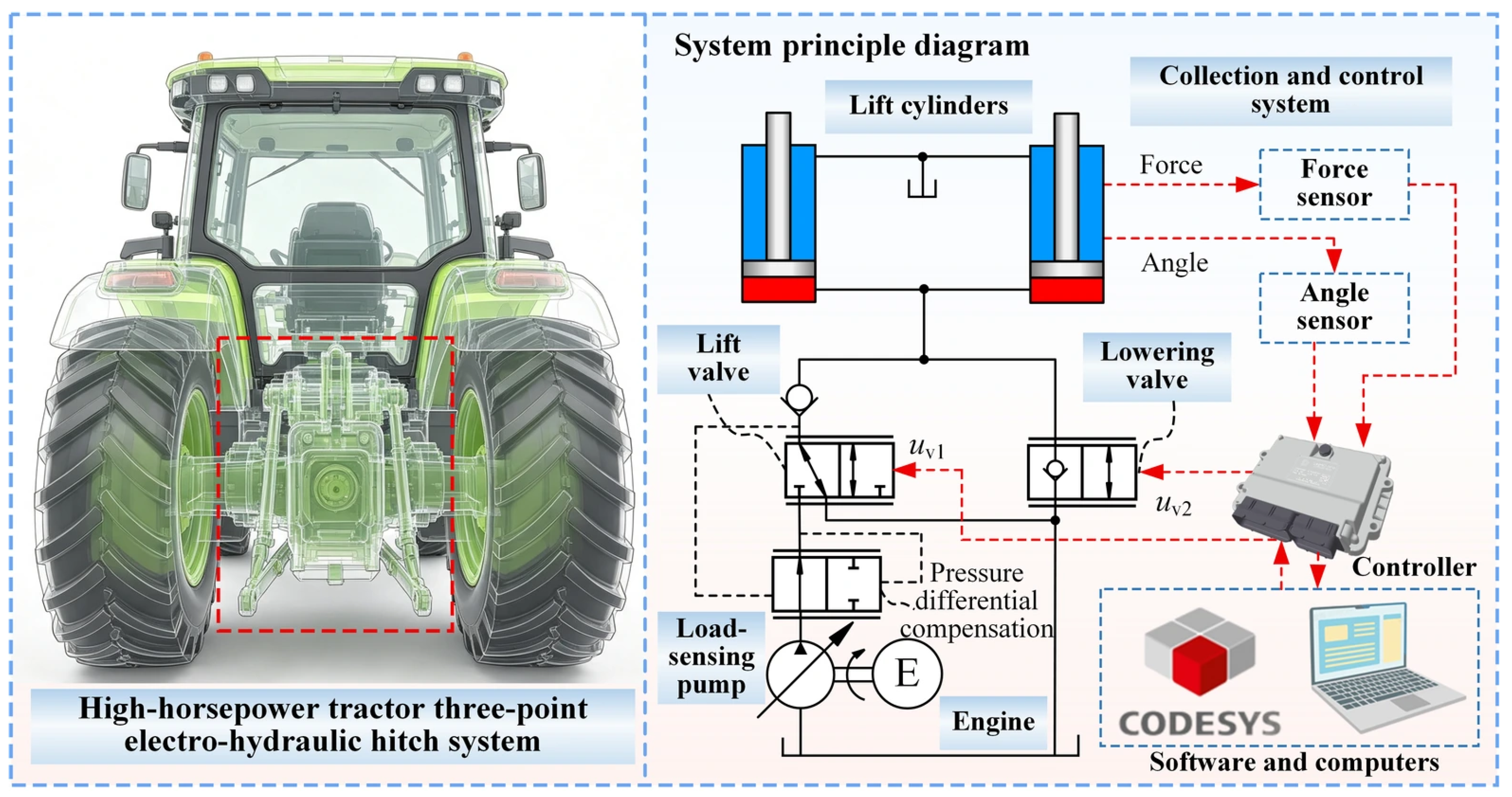
The tractor three-point electro-hydraulic hitch system for high-horsepower tractors consists of three subsystems: the mechanical actuation system, hydraulic power system, and data acquisition and control system, as shown in Figure 1. The mechanical execution system, with the three-point hitch mechanism as its core, is an important carrier for agricultural implement attitude adjustment and operation load transmission. The hydraulic power system is mainly composed of a load-sensing pump, a digital lift valve group, and a hydraulic cylinder, aiming to realize efficient energy conversion and accurate supply. Among them, the displacement control of the load-sensing pump is adjusted according to the oil pressure in the rodless cavity of the hydraulic cylinder to achieve flow matching between supply and demand. The digital lift valve group includes a lift valve and a lower valve. Both the lifting and lowering valves are cartridge-type proportional hydraulic valves. Their valve openings are continuously regulated by electrical actuation signals corresponding to digital control commands generated by the controller, rather than operating only in fully open or fully closed states. A pressure difference compensator is installed at the oil inlet of the lift valve to keep the pressure difference at the valve port constant and reduce the impact caused by load fluctuations, thereby significantly improving the stability of agricultural implement hitch control. The acquisition and control system is mainly responsible for system state perception and system control. It mainly includes an inclination sensor and a force sensor installed on the three-point hitch mechanism, which are used to detect tillage depth and traction force in real time. The controller and the human–machine interaction control panel are used to set operation parameters and control modes.
The controller takes the difference between the set values of tillage depth and traction force and the feedback values from the sensors as the deviation input, combines the force-position comprehensive weighting coefficient, calculates through the fuzzy PID control law, and then outputs the control signal for the digital hydraulic valve to drive the agricultural implement to perform lifting or lowering actions. When the controller outputs a forward control signal, the lift valve is energized and opens. The high-pressure oil output by the load-sensing pump flows through the pressure difference compensator, the lift valve, and the check valve in sequence, and enters the rodless cavity of the hydraulic cylinder. As the pressure in the rodless cavity rises, the piston rod of the hydraulic cylinder extends outward, pushing the three-point hitch mechanism to drive the agricultural implement to rise, realizing the lifting action. When the controller outputs a negative control signal, the lower valve is energized and opens. At this time, the rodless cavity of the hydraulic cylinder is connected to the oil return circuit. The agricultural implement pulls the piston rod to retract under the action of its own gravity and the reaction force of the soil, and the oil in the rodless cavity is squeezed and flows back to the oil tank through the lower valve, completing the lowering action of the agricultural implement. In the above process, the pressure difference compensator installed at the oil inlet of the lift valve ensures that the pressure difference at the valve port is not affected by load fluctuations, so that the lifting speed is only determined by the opening of the valve core, thus ensuring the speed stability and controllability of the lifting action.

2.2. Model of Electro-Hydraulic System for Agricultural Implement Hitch

Based on the working principle of the suspended electro-hydraulic system, a theoretical model of the agricultural implement suspended electro-hydraulic system is established, covering the load-sensing pump, digital lift valve group, hydraulic cylinder and three-point hitch mechanism, which lays a foundation for the subsequent control system design and simulation analysis. During the modeling process, the oil is assumed to be an ideal incompressible fluid. The pressure loss along the pipeline and local throttling loss are ignored. The internal and external leakage of the hydraulic cylinder is treated as linear leakage. The influence of oil temperature change on oil viscosity is not considered.

2.2.1. Flow Model of Load-Sensing Pump

The displacement control of the load-sensing pump is adjusted based on the pressure of the rodless chamber of the hydraulic cylinder to achieve supply-demand flow matching. Its core lies in the dynamic balance between the pump’s displacement adjustment mechanism and the pressure feedback link.
This system adopts a load-sensing pump, whose output flow is adaptively adjusted with the load pressure of the rodless chamber of the hydraulic cylinder to achieve on-demand flow matching.
The output flow Q p of a load-sensing pump can be expressed as:
Q p = V p n p η v
where V p is the pump displacement; n p is the driving speed; and η v is the volumetric efficiency.
The displacement of the load-sensing pump is regulated according to the difference between the actual pressure margin and its preset value. To describe the dynamic response of the load-sensing regulating mechanism, an equivalent first-order relationship is adopted:
τ L S d V p d t = K L s Δ p L s ( p p p L s )
where τ L S is the equivalent time constant of the load-sensing regulating mechanism; K L s is the equivalent regulating gain; p p is the pump outlet pressure; p L s is the load-sensing pressure corresponding to the actuator load; Δ p L s is the preset load-sensing pressure margin.
When the actual pressure margin falls below the preset value, the regulating mechanism increases the pump displacement to increase the supplied flow and pressure. Conversely, when the pressure margin exceeds the preset value, the pump displacement is reduced. Therefore,
p p p L s = Δ p L s
Thus, the load-sensing pump maintains an approximately constant pressure margin above the load pressure and adjusts its displacement according to the instantaneous load demand, thereby reducing unnecessary throttling losses.

2.2.2. Complete Dynamic Model of Digital Valve Block with Differential Pressure Compensator

The digital poppet valve group consists of a poppet valve, a lowering valve and a pressure difference compensator. The control signal of the poppet valve comes from the output of the controller, which is converted into the driving force of the valve core by the electromagnet to control the opening degree of the valve port.
  • Flow equation of the proportional directional valve
The proportional directional valve is a throttle valve. The flow rate Q v through the valve port is related to the port area A v and the pressure differential Δ p v across the port by the orifice flow equation:
Q v = C d A v 2 ρ f d Δ p v
where C d is the discharge coefficient and ρ f d is the fluid density. The port area A v is determined by the spool displacement x v . For a spool-type valve structure, A v = w x v , where w is the area gradient of the port.
The transfer function between the spool displacement x v and the input control current can be approximated as a second-order oscillatory element:
x v s i s = k v ω v 2 s 2 + 2 ζ v ω v s + ω v 2
where k v is the gain coefficient of the valve; ω v is the natural frequency of the valve; and ζ v is the damping ratio.
2.
Pressure compensator model
A pressure compensator installed at the inlet of the proportional valve is intended to maintain a constant pressure differential across the valve, reducing the influence of load fluctuations on flow control. According to the operating principle of the pressure compensator, the force balance equation on the compensator spool is given by:
p p A c = p 1 A c + k c x c 0 + x c + F f
where A c is the effective area of the compensator spool; p p and p 1 are the pressures acting on the spool; k c is the spring stiffness; x c 0 is the spring pre-compression; x c is the spool displacement from the neutral position; and F f is the steady-state flow force.
Rearranging gives the compensator spool displacement:
x c = A c p p p 1 k c x c 0 F f k c
Since p p p 1 = Δ p v , the pressure compensator maintains Δ p v near the spring setting by adjusting the spool displacement. When the load pressure p 1 increases, the spool shifts to the right, enlarging the compensator orifice opening, which causes the pump outlet pressure p p to rise correspondingly, thereby keeping Δ p v constant. Under ideal compensation conditions, the pressure differential across the proportional valve port is Δ p v p s e t , so the flow rate through the proportional valve is determined solely by the spool opening:
Q v = C d w x v 2 Δ p s e t ρ f d
This indicates that the incorporation of the pressure compensator decouples the lifting speed from the load, significantly improving the smoothness of hitch control.
3.
Lowering valve model
The lowering valve is also a proportional cartridge valve whose opening is continuously regulated by the control command. Its characteristics in the open state also obey the orifice flow equation. When the controller outputs a negative signal, the lowering valve opens, connecting the piston-side chamber of the hydraulic cylinder to the return line. Since the return line pressure is approximately zero, the pressure differential across the lowering valve port is equal to the piston-side chamber pressure p 1 , and the return flow rate is given by:
Q d = C d d A d 2 ρ p 1
where Q d is return flow rate; C d d is the discharge coefficient of the lowering valve; and A d is the port area of the lowering valve.

2.2.3. Hydraulic Cylinder Model

The hydraulic cylinder is a single-rod double-acting cylinder. The flow continuity equation for the piston-side chamber can be expressed as:
Q 1 = A 1 d y d t + V 1 β e d p 1 d t + C i p p 1 p 2 + C e p p 1
where Q 1 is the piston side chamber flow rate; A 1 is the effective area of the piston-side chamber; y is the piston displacement; V 1 is the volume of the piston-side chamber; β e is the effective bulk modulus of the fluid, and the hydraulic fluid is treated as weakly compressible with a finite effective bulk modulus; p 1 and p 2 are the pressures in the piston-side and rod-side chambers, respectively; C i p is the internal leakage coefficient; and C e p is the external leakage coefficient. The flow continuity equation for the rod-side chamber is analogous.
The force balance equation for the piston of the hydraulic cylinder is:
p 1 A 1 p 2 A 2 = m e q d 2 y d t 2 + B c d y d t + F l o a d
where A 2 is the effective area of the rod-side chamber; m e q is the equivalent mass; B c is the viscous damping coefficient; and F l o a d is the load force.

2.2.4. Kinematics Model of the Hitch Mechanism

The three-point linkage mechanism converts the linear displacement of the hydraulic cylinder into the lifting/lowering motion of the implement. In the linkage mechanism consisting of the upper link and the lower links, the kinematic relationship between the piston displacement y of the hydraulic cylinder and the implement lift angle θ is given by:
y = f θ
By linearising the relationship for small displacements, we can obtain:
Δ y = J Δ θ
where J = d y d θ is the Jacobian matrix, θ is the lift angle.
The initial working depth and initial hitch angle are explicitly defined as the reference configuration.
h = h 0 L t o o l sin θ 0 + Δ θ sin θ 0
where h 0 is the initial working depth; L t o o l is the equivalent lever arm from the hitch point to the implement bottom; and θ 0 is the initial lift angle.
The measured forces are projected onto the tractor travelling direction to obtain the draft force:
F d r a f t = F L L cos γ L + F L R cos γ R
where F L L and F L R are the forces measured by the left and right lower-link sensors, cos γ L and cos γ R are the corresponding angles relative to the travelling direction. Under quasi-static conditions, the draft force is further related to the soil resistance and the gravitational component of the implement along the travelling direction.

2.2.5. Overall System Model

Combining the load-sensing pump, digital valve block, hydraulic cylinder, and three-point hitch mechanism, the nonlinear dynamic model implemented in the simulation is obtained by coupling the governing equations of the individual subsystems described above. To explicitly present the state equations used in the simulation, the state vector is defined as:
x = y , y ˙ , p 1 , p 2 , x v , x c , V p T
The state vector and control input are defined as:
u = i r a i s e i l o w e r T
The hitch angle is determined from the kinematic relation and the system outputs are:
h F t r a c = h 0 L t o o l sin θ 0 + θ F s o i l + G t o o l sin α
This model describes the complete dynamic process from the control signal inputs to the outputs of working depth and traction force, providing a theoretical basis for subsequent controller design and system simulation.

3. Control Strategy

3.1. Multiple Control Modes for Agricultural Implement Hitching

The tractor implement hitch system mainly adopts three control modes: tillage depth control, traction control, and force-position compound control. Tillage depth control takes the soil tillage depth as the direct control objective. It mainly ensures the uniformity of tillage depth by maintaining a constant tillage depth of the implement, and is suitable for operating conditions with flat ground and uniform soil texture. Traction control takes constant traction resistance as the control objective. It can mainly stabilize the engine load and suppress drive wheel slippage, but has the problem of large tillage depth fluctuations. Force-position compound control can take into account both consistent tillage depth and engine load stability. On the one hand, traction regulation is realized through tillage depth adjustment to maintain stable engine load. On the other hand, it can suppress the severe tillage depth fluctuation under pure traction control and ensure tillage quality.
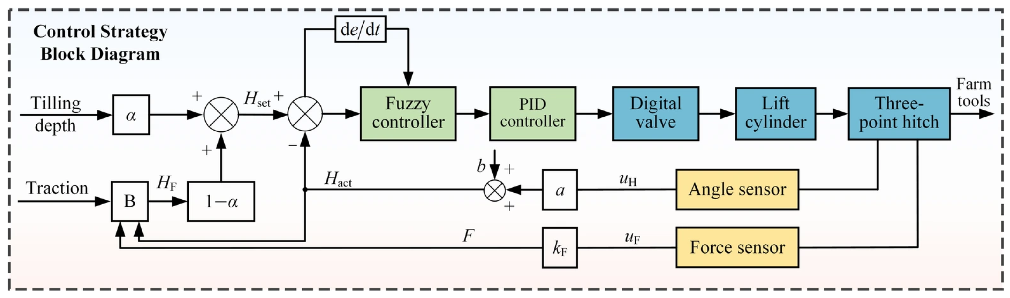
Figure 2 shows the block diagram of the control strategy for the electro-hydraulic system of the implement hitch. In the traction parameter setting link, the soil resistance corresponding to unit tillage depth is introduced, and the soil resistance condition is perceived in real time according to the real-time monitored tillage depth and traction feedback values. The set traction value is converted into a tillage depth value. When the soil resistance increases, the tillage depth value corresponding to the set traction decreases, the hydraulic cylinder piston rod extends, and the implement is lifted. When the soil resistance decreases, the tillage depth value corresponding to the set traction increases, the hydraulic cylinder piston rod retracts, and the implement is lowered.
The control modes of the implement hitch system achieve coordinated switching and regulation between tillage depth control and draft force control by setting a weighting coefficient α t x . Specifically, the controller synthesizes the tillage depth setpoint and the draft force setpoint (converted from draft force into an equivalent tillage depth) into a unified tillage depth command. When α t x = 1 , the system operates in the pure tillage depth control mode, where regulation is based on the deviation of the tillage depth. When α t x = 0 , the system switches to the pure draft force control mode, tracking the draft force target in the form of an equivalent tillage depth. When 0 < α t x < 1 , the system is in the force-position compound control mode, where both tillage depth and draft force participate in the control decision according to their respective weights. During field operation, an inclination angle sensor mounted on the three-point hitch mechanism detects the implement attitude angle in real time. The feedback voltage signal u h is linearly and positively correlated with the measured tillage depth H a c t , thereby providing a reliable sensing input for the closed-loop tillage depth control.
H a c t = k H u H + b H
where u H is the sensor output voltage, k H is the calibration gain; and b H is the calibration offset.
Based on the draft force detected by the force sensor and in combination with the actual tillage depth, the variation in the soil resistance per unit tillage depth, denoted as B t , can be obtained. When the measured tillage depth H a c t 0 , the soil resistance B t equals the initial value of unit soil resistance B 0 when the implement has not yet entered the soil. When the measured tillage depth H a c t > 0 , the expression for B t is given by:
B t = F t H a c t
where B t is the soil resistance per unit tillage depth, and B 0 is the initial value of the soil resistance per unit tillage depth.
The unit of B t is N/m. It differs from the conventional soil specific resistance q t , which is defined as the draft force per unit tilled cross-sectional area. For an implement with an effective working width, their relationship expression is:
q t = B t b
where q t is the conventional soil specific resistance; and b is an effective working width.
In addition, to avoid noise amplification when H a c t approaches zero, a minimum effective depth threshold H m i n is introduced. When H a c t H m i n , B t is assigned its initial value. When H a c t > H m i n , B t is obtained through calculation.
Furthermore, the expression for F t in the above equation is given by:
F t = μ f k f
where μ f is the voltage from the force sensor; and k f is the force corresponding to one unit of voltage from the force sensor.
Then, H c denotes the prescribed tillage-depth command of the depth-control branch, whereas H f is the equivalent tillage-depth command converted from the prescribed draft force:
H f = F s e t B t
where H f is the setting value of the plowing depth calculated based on the traction force setting value; and F s e t is the setpoint of draft force.
When 0 < α t x < 1 , the system operates in the force-position compound control mode, and the setpoint of tillage depth is given by:
H s e t = α t x H c + ( 1 α t x ) H f = α t x H c + ( 1 α t x ) F s e t B t
where H s e t is the tillage depth setpoint in the depth control loop.

3.2. Fuzzy PID Algorithm

To enhance the control performance of the electro-hydraulic hitch system for the high-horsepower tractor implement under field conditions, this paper adopts a fuzzy PID control algorithm for closed-loop tillage depth control, aiming to improve the system’s dynamic response and steady-state accuracy under load disturbances, parameter variations, and nonlinear effects.
The fuzzy PID controller is designed with the tillage depth deviation e H and its rate of change e c as the state variables characterizing the system. The tillage depth deviation is defined as the difference between the setpoint depth and the measured depth. The rate of change of the depth error is obtained by differentiating the deviation, which reflects the temporal trend of the depth deviation and serves as an important basis for the controller to perform lead adjustment.
e H = H s e t H a c t e c = d e H d t
where e H is the tillage depth deviation; and e c is the rate of change of the depth deviation.
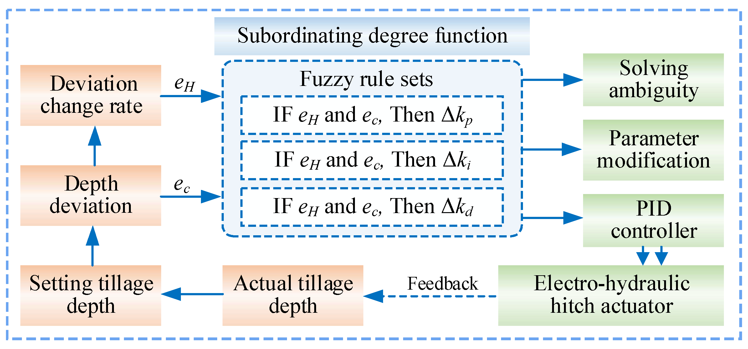
Figure 3 presents the block diagram of the fuzzy PID control system for tillage depth regulation. The system takes the tillage depth error and its rate of change as the inputs to the fuzzy controller. Through fuzzy inference based on a predefined rule base, the controller outputs the correction values for the PID parameters. These corrections are then used to tune the PID controller gains, which in turn generate the control signals for the electro-hydraulic hitch actuator. In this manner, a closed-loop tillage depth control is realized.
Based on the actual operating conditions and the response range of the actuator, the universes of discourse for the fuzzy controller inputs are determined. The basic universe for the depth deviation e H is set to [−40, 40], covering the maximum possible deviation range encountered in conventional deep tillage operations. The basic universe for the rate of change of depth error e c is set to [−1000, 1000], which accounts for rapid depth fluctuations caused by sudden changes in soil resistance in the field.
The fuzzy controller adopts a typical two-input, three-output structure. With e H and e c as input variables, it performs fuzzification to convert the precise continuous physical quantities into fuzzy linguistic variables, which are then mapped onto corresponding fuzzy subsets through predefined membership functions. The output variables are the correction terms for the three PID controller parameters, namely the proportional gain correction Δ k p , the integral gain correction Δ k i , and the derivative gain correction Δ k d . The final PID parameters are obtained by adding these corrections to the respective base parameters, as expressed in the following equation.
k p = k p 0 + Δ k p k i = k i 0 + Δ k i k d = k d 0 + Δ k d
where k p 0 , k i 0 , and k d 0 are the initial values of the proportional, integral, and derivative gains, respectively, set according to empirical experience; Δ k p , Δ k i , and Δ k d are the correction values computed and output in real time by the fuzzy controller based on the current deviation state.
Furthermore, the detailed controller parameters are summarized in Table 1.
The key to fuzzy control lies in the control rules. Based on the relationship between plowing depth error, error change rate, and correction parameters, as well as the working characteristics of the agricultural implement hitch electro-hydraulic system, the fuzzy control rules shown in Table 2 are formulated. Based on the plowing depth error and its change rate, fuzzy logic is used to adjust the proportional, integral, and derivative coefficients.
The control signal output by the fuzzy PID controller is used to drive the spool action of the digital hydraulic valve group after digital-to-analog conversion, so as to control the lifting movement of the agricultural implement. According to the system control logic, the polarity of the control signal determines the action direction and object of the actuator, and the specific mapping relationship is described as follows.
When e H < 0 , the actual tillage depth is greater than the setpoint and the implement needs to be raised. The controller therefore generates a positive command u v > 0 , which actuates the raising valve. Conversely, when e H > 0 , the actual tillage depth is smaller than the setpoint and the implement needs to be lowered. The controller generates a negative command u v < 0 , which actuates the lowering valve. When e H = 0 and u v = 0 both valves remain closed, and the implement maintains its current position.
However, digital hydraulic valves have an inherent dead-zone characteristic at the beginning of the spool stroke. When the control signal varies within a certain amplitude range, the spool does not actually move, which may cause the controller’s regulation action to fail under small-deviation conditions, resulting in steady-state errors or limit-cycle oscillations. To eliminate the influence of the dead zone on control accuracy, a dead-zone compensation strategy must be introduced into the control algorithm.
Let the actual displacement of the digital valve spool be x v , and the voltage control signal output by the controller be u v . The relationship between them is expressed as follows:
x v = 0 u v < u d K v ( u v u d )   u v > u d K v ( u v + u d )   u v < u d
where u d is the dead-zone voltage threshold of the digital valve; and K v is the gain coefficient relating voltage to spool displacement.
In Equation (28), u d = 0.8   V and K v = 0.12   mm / V . These parameters are determined from a static valve calibration test. The command voltage is gradually increased in both positive and negative directions from zero, and the corresponding spool displacement is recorded. The dead-zone threshold is identified as the minimum command magnitude at which a measurable spool displacement occurred. After excluding the dead-zone region, K v is obtained by linear fitting of the spool displacement against the effective command voltage.
The model indicates that when the amplitude of the control signal is less than the dead zone threshold, the valve spool remains stationary and the system has no response; when the amplitude of the control signal exceeds the dead zone threshold, the displacement of the valve spool is proportional to the effective control signal. In actual control, inverse dead zone compensation is performed on the output signal of the controller. After detecting the direction of the input signal, an additional bias signal equal to the dead zone threshold is superimposed, so that the valve spool can cross the dead zone at the initial moment when the control instruction is issued and enter the effective adjustment range, thus ensuring precise control under small deviation working conditions.

4. Establishment of Simulation Model and Simulation Analysis

4.1. Simulation Model

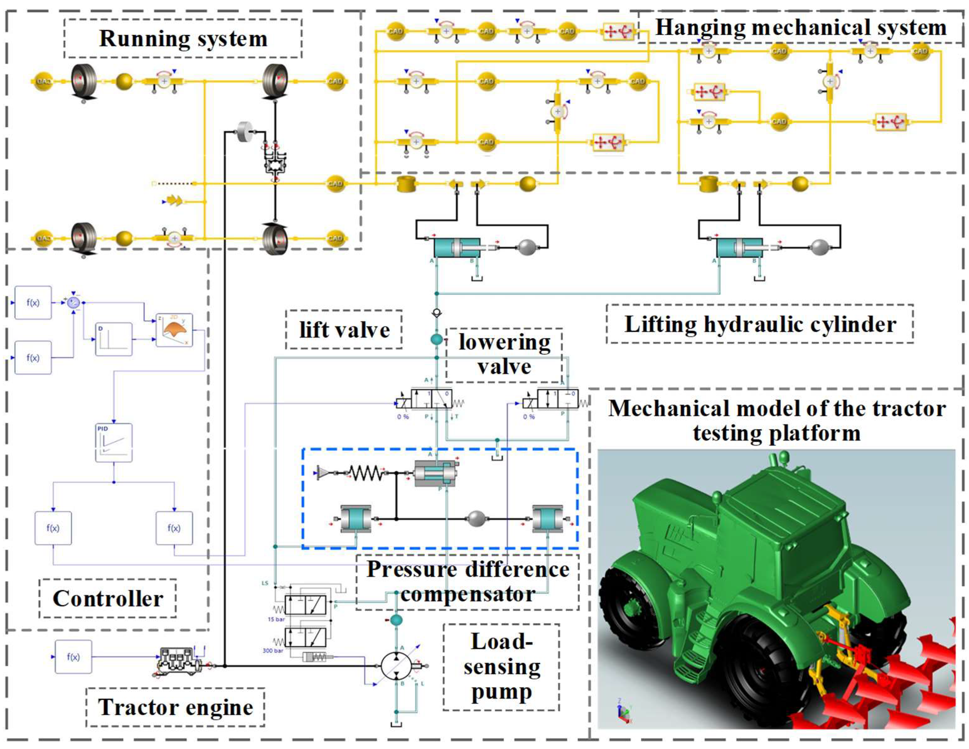
To accurately obtain the mapping relationship between the hitch angle variation during the motion of the agricultural tool hitch mechanism and the tillage depth, and to systematically evaluate the feasibility and control performance of the force-position composite control strategy proposed in this paper under various operating conditions, this chapter establishes a complete simulation model of a high-horsepower tractor based on a multidisciplinary joint simulation platform, as shown in Figure 4. This simulation model was developed using the Simulation X multi-domain unified modeling software.
The complete system simulation model consists primarily of three subsystems: the mechanical system, the hydraulic system, and the control system. The mechanical system serves as the physical execution unit for the agricultural implement’s hitch operation, encompassing the tractor chassis dynamic model, the walking mechanism model, and the three-point hitch mechanism model. The hydraulic system acts as the power transmission and actuation component of the electro-hydraulic hitch system, primarily comprising the load-sensitive pump model, the digital lifting valve set model (containing the lifting valve, lowering valve, and differential pressure compensator), and the double-acting hydraulic cylinder model. The control system constitutes the core hub for achieving closed-loop regulation of the tillage depth, and includes the sensor model, the controller model, and the control algorithm model.
The multi-domain coupling between the mechanical, hydraulic, and control systems is implemented by establishing a standard interface using Simulation X. The mechanical system transmits the hitch angle and load force information to the hydraulic system as boundary conditions; the hydraulic system then feeds the actuator force from the hydraulic cylinder back to the driving mechanism of the mechanical system to drive its motion, while simultaneously transmitting the pressure and displacement state variables to the control system for closed-loop feedback. This multi-domain coupled simulation modeling approach can accurately reproduce the dynamic behavior of the hitch system under field operation conditions, thereby providing a reliable simulation platform for the subsequent comparative validation of control strategies.
The simulation was conducted under controlled and repeatable disturbance conditions to evaluate the controller response and support parameter tuning. The imposed periodic load disturbance was not intended to reproduce the stochastic soil resistance encountered during field operation exactly. Therefore, following model calibration and closed-loop simulation, field experiments were conducted as an independent system-level validation to determine whether the control performance predicted by the simulation could be maintained under actual tillage conditions.
The key parameters used in the SimulationX model are summarized in Table 3. The parameters cover the main hydraulic, mechanical, load, and sensor characteristics that directly affect the dynamic response of the electro-hydraulic hitch system.

4.2. Simulation Analysis

During the simulation analysis, a calibration test was conducted on the hitch system. While the tractor was stationary, a continuous control signal was applied to the lifting hydraulic cylinder, causing its piston rod to extend gradually from the fully retracted position to the fully extended position, covering the entire travel range of the hitch mechanism. During this process, the feedback voltage signal from the upward tilt angle sensor on the three-point hitch mechanism and the vertical position of the agricultural implement’s base relative to the ground surface were recorded simultaneously, thereby obtaining corresponding data for both voltage and displacement.
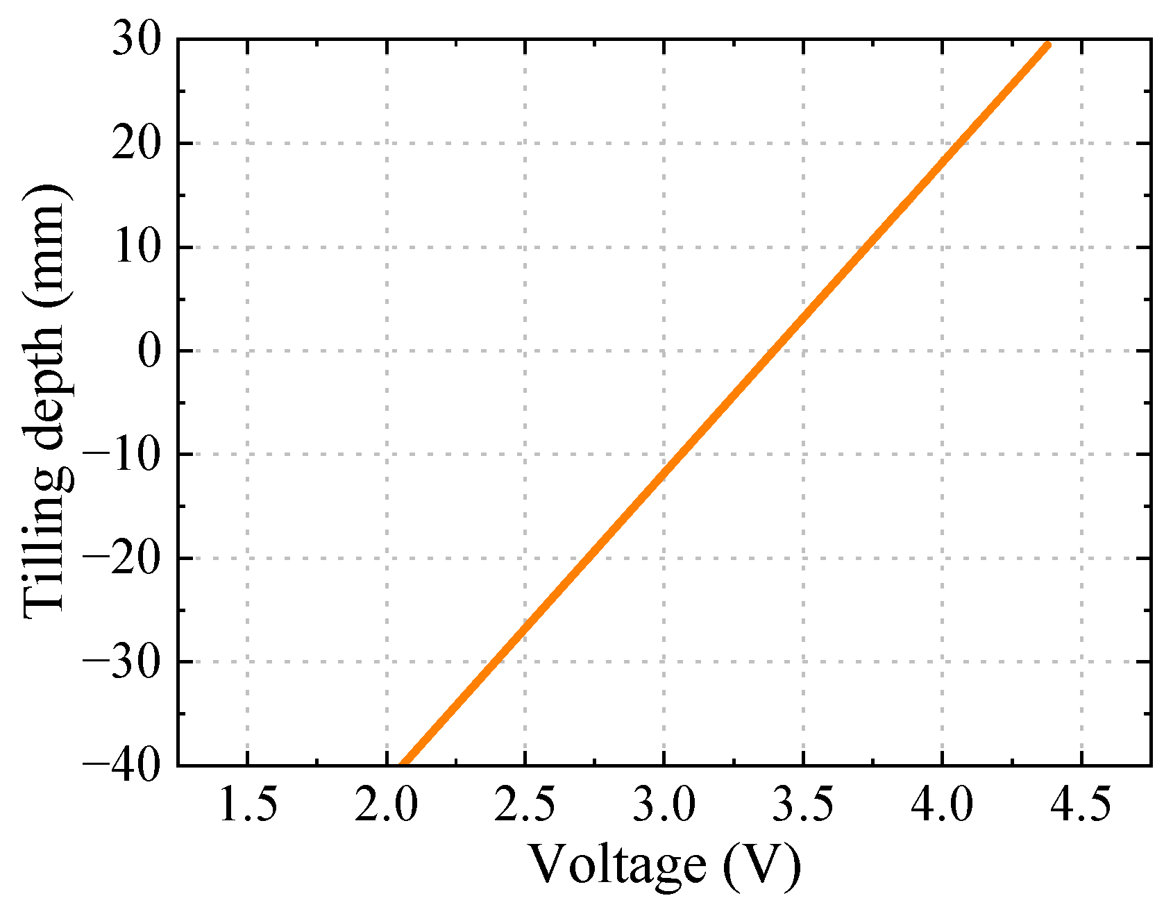
Figure 5 shows the relationship curve between the tilt angle sensor’s voltage output and the tillage depth during the calibration process. In this curve, negative values represent the tillage depth—i.e., the depth at which the agricultural tool operates—and positive values represent the lifting height—i.e., the ground clearance after the agricultural tool is raised off the ground. The curve exhibits a good linear characteristic overall, indicating that within the effective working stroke range of the hitch mechanism, there exists a direct proportional relationship between the tilt angle sensor’s output voltage and the position of the agricultural tool. By performing a linear regression fit on the aforementioned measurement data, the conversion equation relating the tillage depth of the agricultural tool to the angle sensor’s voltage is obtained as follows:
H a c t = 29.92 u v 101.53
The linear calibration yielded R 2 = 0.996 and an RMSE of 1.18 mm, confirming a strong linear relationship between the angle-sensor output voltage and the implement vertical position within the effective operating range. During the control process, the controller collects the voltage signals from the tilting angle sensor in real time; based on the conversion relationship, it can calculate the current measured tillage depth, thereby providing real-time position feedback for tillage depth control.
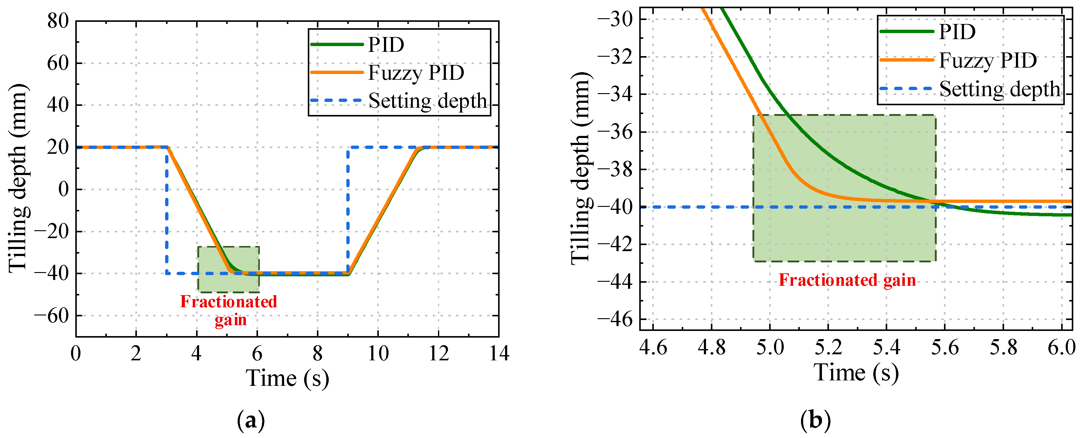
To compare the influence of different control algorithms on the position tracking performance of the implement, simulations were conducted under no-load conditions using conventional PID and fuzzy PID control, respectively. The step response curves of the lifting and lowering processes are presented in Figure 6.
As shown in Figure 6a, both control methods effectively track the position command, yet their dynamic responses differ significantly. In the initial stage with large position deviation, the fuzzy PID controller generates a larger control signal, which maintains a greater valve opening of the digital hydraulic valve and thus achieves a faster response speed. The settling time of the step response under fuzzy PID control is 2.01 s, compared with 2.33 s for conventional PID, representing a reduction of approximately 13.7%. This indicates that fuzzy PID improves the system dynamic performance through real-time tuning of PID parameters. During the steady-state phase, the fuzzy PID control curve exhibits smaller fluctuations. The system converges rapidly to the setpoint without noticeable overshoot or oscillation, demonstrating higher steady-state accuracy. This benefit is attributed to the fine adjustment of the integral coefficient by the fuzzy controller within the small-deviation region, which effectively eliminates steady-state error while suppressing integral saturation. As revealed in Figure 6b, which provides a magnified view of the steady-state region in Figure 6a, the conventional PID control still exhibits minor periodic fluctuations after entering the steady state. In contrast, the position output curve under fuzzy PID control is much smoother, with significantly reduced fluctuation amplitude and no observable deviation from the setpoint. This further verifies the advantage of fuzzy PID control in steady-state accuracy.
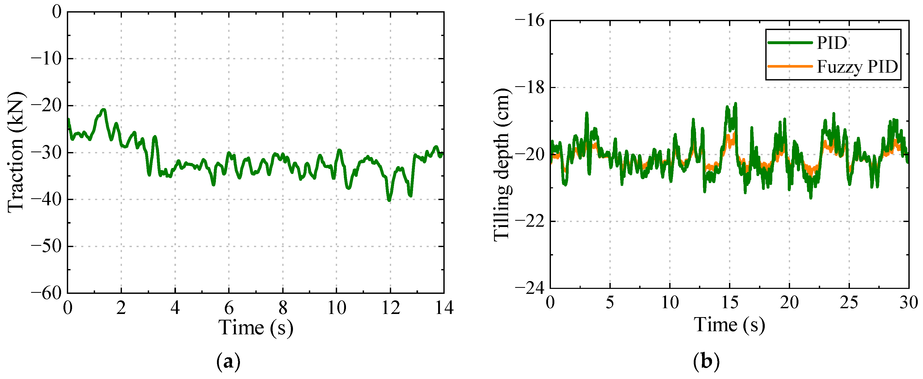
To evaluate the tillage depth maintenance capability of different control algorithms, typical tillage depth operation conditions are set in the simulation model. The horizontal soil operation resistance on the agricultural implement changes dynamically according to the waveform shown in Figure 7a. The resistance amplitude fluctuates periodically in the range of 20 kN to 40 kN, which is used to simulate the random variation of field soil resistance caused by factors such as tillage depth, soil heterogeneity and topographic relief. The set value of tillage depth is fixed at 20 cm, and simulation comparisons are carried out using the traditional PID control and fuzzy PID control algorithms respectively. The obtained dynamic response characteristics of tillage depth are shown in Figure 7b. Under the condition of large fluctuations in soil resistance, both control algorithms can maintain the tillage depth of the agricultural implement near the set value, but there are significant differences in control accuracy and anti-disturbance capability.
When the traditional PID control is adopted, the actual tillage depth of the agricultural implement fluctuates continuously near the set value, the maximum deviation range of the tillage depth error is about 2.5 cm, and the tillage depth stability coefficient is 90.8%. This reflects that the PID controller with fixed parameters is difficult to quickly adjust the control gain to suppress the influence of disturbance under the working condition of sudden load change. When the fuzzy PID control is adopted, although the system has a short-term fluctuation at the moment of the step change of resistance, the controller can adjust the PID parameters in real time according to the tillage depth deviation and its change rate, so that the system can quickly return to the vicinity of the set tillage depth. During the whole operation process, the fluctuation range of tillage depth error is effectively controlled within 1.5 cm, and the tillage depth stability coefficient is 96.4%. The comparison results show that the fuzzy PID controller, relying on its parameter self-tuning capability, can adjust the control strategy in real time according to the error state. As a result, its tillage depth stability and load disturbance resistance are both superior to those of the traditional PID control, which verifies the effectiveness and superiority of the control strategy proposed in this paper in field operations.

5. Experimental Testing

5.1. Agricultural Implement Hitching Test Platform

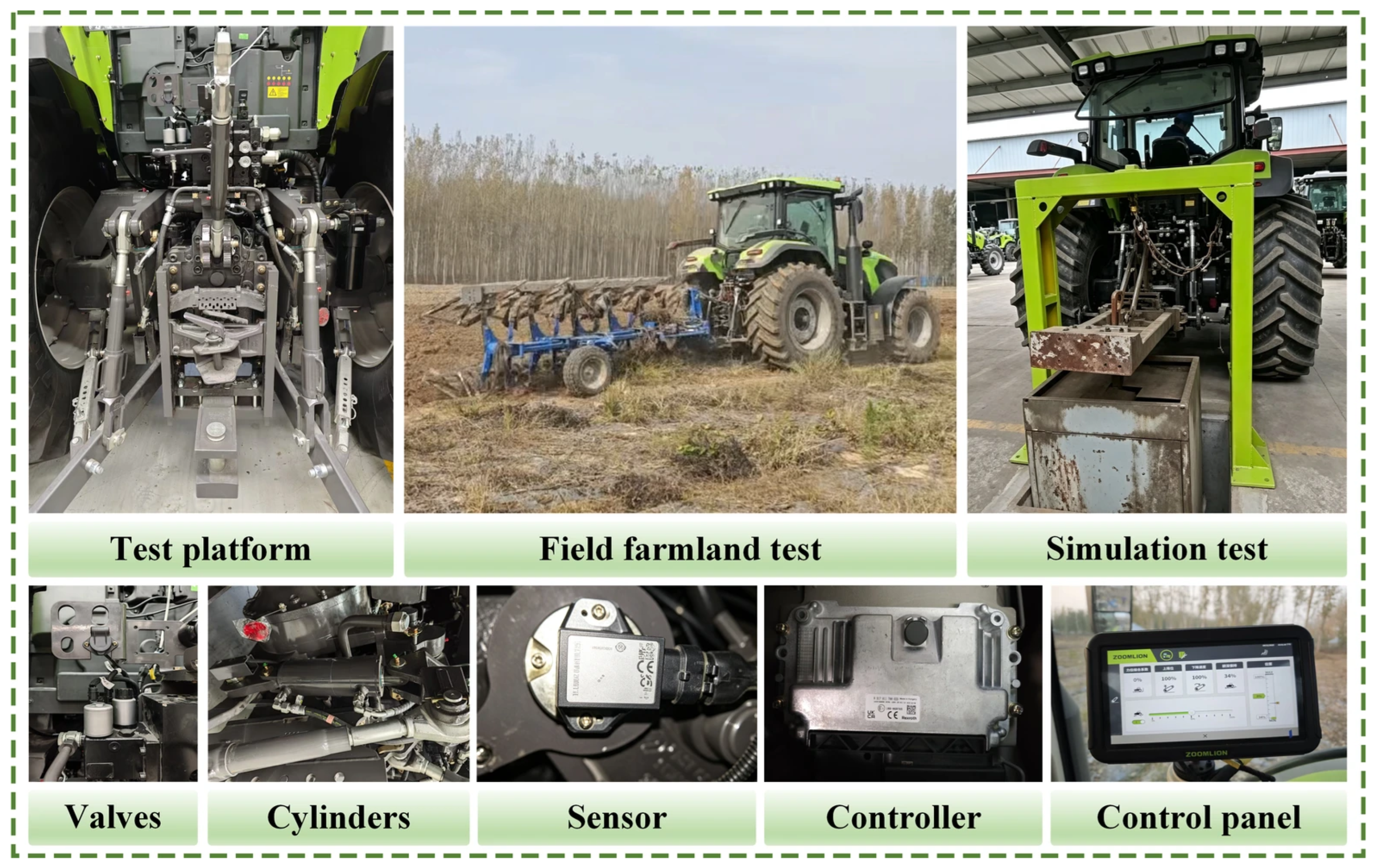
Figure 8 shows the test platform of the electro-hydraulic hitch system for high-horsepower tractor implements and the field test site. Field experiments were conducted from August to November 2025 in Henan Province, China. A PQ2404 high-horsepower wheeled tractor (Zoomlion Heavy Industry Science and Technology Co., Ltd., Changsha, Hunan, China) with a rated engine power of 176.5 kW and a rated drawbar pull of no less than 75 kN was used in the tests. The travelling speed was maintained at approximately 5 km/h during tillage operations. The mounted implement was a five-furrow moldboard plow with a working width of 2.25 m, designed for dryland tillage operations, with a total mass of 1200 kg. The hydraulic system employed a 5xSB24-EHS4/EHR24-EHS4 multi-way valve (Bosch Rexroth AG, Lohr am Main, Bavaria, Germany). The software version used was CODESYS V3.5.
The experimental field was selected from a plot previously cropped with maize, representing typical farmland tillage conditions in the region. The soil was classified as silt loam according to the soil textural classification system. Soil bulk density was determined using the core sampling method at a depth of 0–20 cm, with a mean value of 1.32 g/cm3. Soil moisture content was determined by the oven-drying method on a wet basis. A total of 15 soil samples were collected across the experimental field before tillage, yielding a mean moisture content of 35%. Soil compactness was evaluated using a digital cone penetrometer at the same measurement depth. Five measurement locations were selected across the field, with five replicate measurements conducted at each location, resulting in a mean cone index of 350 kPa. All soil measurements were performed prior to the tillage experiments on the test day.
During the field tests, TN5200-series angle sensors (Hirschmann Automation and Control GmbH, Neckartenzlingen, Germany) with an accuracy of ±0.1° were employed to collect real-time attitude inclination data of the hitch mechanism, and TJH-4A force sensors (Anhui Tianguang Sensor Co., Ltd., Bengbu, Anhui, China) with an accuracy of ±0.5% F.S. were used to acquire the implement draft resistance signals. A controller served as the data acquisition and core control unit of the entire system, responsible for signal acquisition, control algorithm computation, and output command generation. Real-time data exchange and command transmission between the digital hydraulic valve and the controller were accomplished via an industrial bus protocol.
The tests were conducted sequentially, beginning with lifting and lowering step-response tests to evaluate the basic dynamic characteristics of the electro-hydraulic hitch system, followed by tillage-depth control and traction-force control tests comparing conventional PID and fuzzy PID control under the same operating conditions. Finally, force-position combined control tests were conducted to evaluate the coordinated regulation of tillage depth and traction force. During the field experiments, tillage-depth and traction-force signals were continuously recorded for subsequent evaluation of the control performance.

5.2. Analysis of Test Results

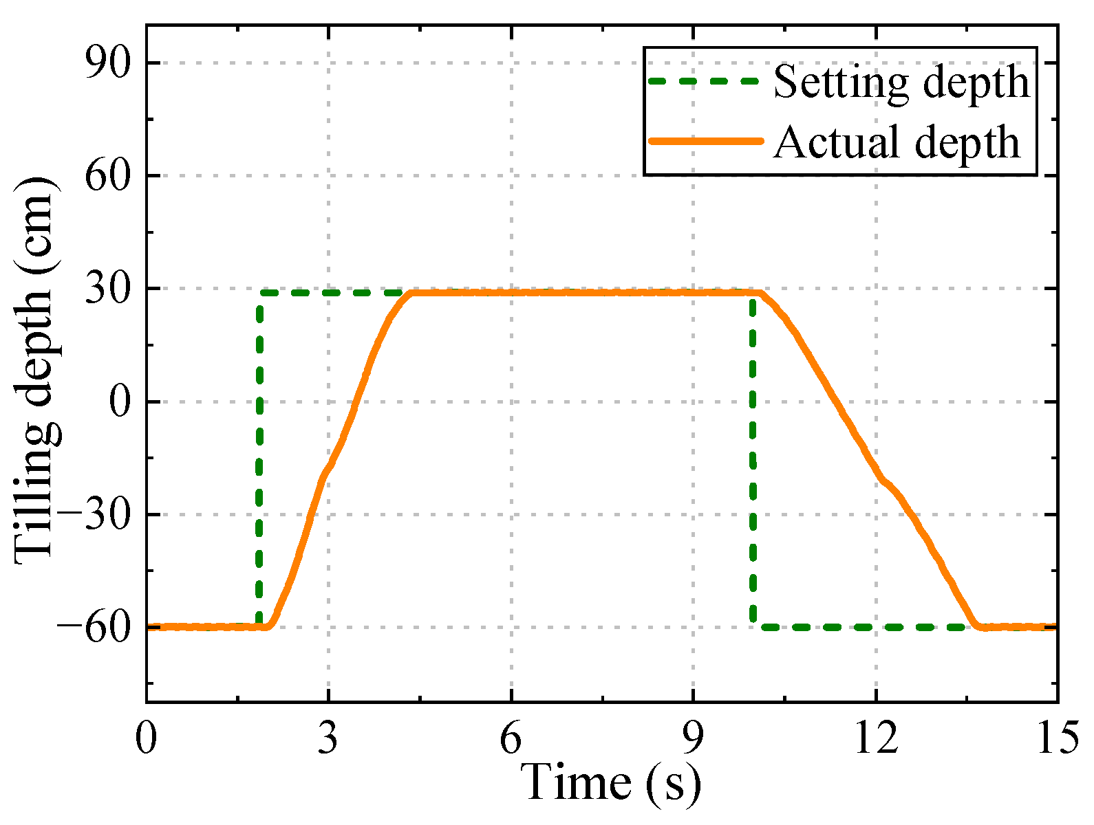
To comprehensively evaluate the lifting dynamic response characteristics of the agricultural implement hitch electro-hydraulic system, a simulated load block with the same mass as the agricultural implement is installed on the hitch mechanism to simulate the hitch inertial load under actual operating conditions. The mass of the load block used to simulate the implement load was approximately 1200 kg. The hydraulic cylinder (Zoomlion Heavy Industry Science and Technology Co., Ltd., Changsha, Hunan, China) had a stroke of 200 mm, with a piston-side effective area of 7.85 × 10⁻³ m2 and a rod-side effective area of 6.13 × 10⁻³ m2. The system was powered by a load-sensing pump (Bosch Rexroth AG, Lohr am Main, Bavaria, Germany) with a maximum displacement of 45 mL/r and a rated pressure of 20.5 MPa. At a pump speed of 1500 r/min, the theoretical flow rate was approximately 67.5 L/min. The digital hydraulic valve had a rated flow capacity of 80 L/min. During the simulated-load test, a step position command from the lowest to the highest hitch position was applied to evaluate the lifting response, followed by a lowering command to evaluate the return response. Each test was repeated three times under the same operating conditions, and the averaged response curve is presented in Figure 9.
After the controller outputs the positive lifting command, high-pressure oil supplied by the load-sensing pump enters the rodless chamber of the hydraulic cylinder through the pressure-difference compensator and lifting valve, driving the piston rod to extend against the gravitational load. During the lifting process, the piston displacement increases smoothly, and the total time from the lowest to the highest position is approximately 2.4 s, indicating a stable and rapid lifting response under the simulated load. When the controller outputs the negative lowering command, the lowering valve opens, allowing the oil in the rodless chamber to return to the tank under the gravitational load and causing the piston rod to retract. Since the lowering process is primarily gravity-driven, its speed is constrained by the valve opening and hydraulic back pressure. Consequently, the total time from the highest to the lowest position is approximately 3.5 s, which is longer than that of the lifting process.
To quantitatively evaluate the stability of the tillage depth and traction force, the stability coefficient is defined as:
S = ( 1 σ x x ¯ ) × 100 %
where x ¯ and σ x are the mean and standard deviation of the measured variable, respectively. A higher stability coefficient therefore indicates smaller relative fluctuations and better control stability.
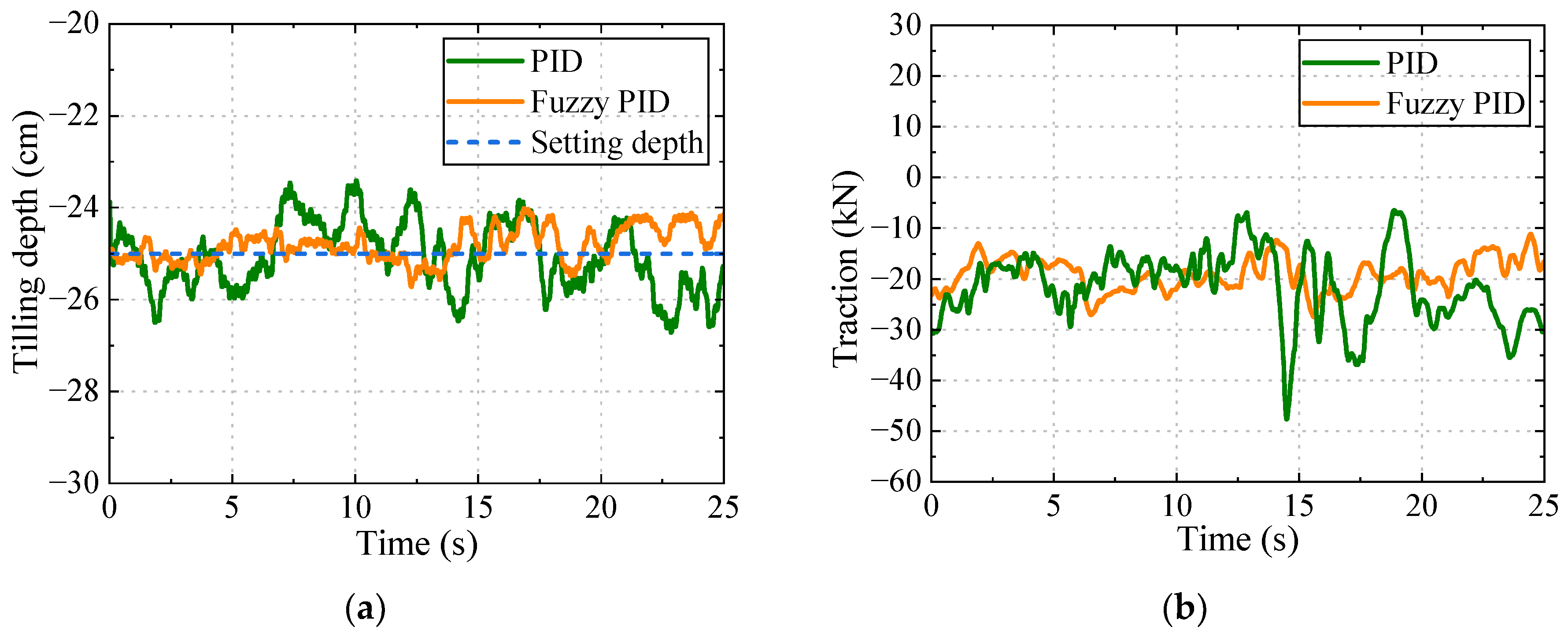
To verify the actual operating performance of the fuzzy PID controller in the tillage-depth control mode, field tests were conducted with a target tillage depth of 25 cm. The ground surface was defined as the zero reference for tillage depth, with negative tillage-depth values representing downward displacement below the ground surface. Accordingly, a tillage depth of 25 cm is represented as −25 cm in the figures. Negative traction-force values represent the draft resistance acting opposite to the forward motion of the tractor. To ensure a valid comparison, the conventional PID and fuzzy PID controllers were evaluated in adjacent test strips within the same experimental field under comparable soil and operating conditions. The same tractor, five-furrow plow, implement configuration, target tillage depth, and operating parameters were maintained for both control methods. The two control algorithms were tested sequentially on the same day, and each test was repeated three times. Sensor signals were synchronously recorded at a sampling frequency of 100 Hz, and the reported performance indices were calculated from the averaged results of three repeated field tests to reduce the influence of random spatial variations in the field. Figure 10 shows the tillage-depth responses and the corresponding traction-force variations.
As shown in Figure 10a, both controllers can track the target tillage depth. However, owing to the continuously varying soil resistance under field conditions, the tillage depth exhibits noticeable fluctuations. Compared with the conventional PID controller, the fuzzy PID controller maintains the tillage depth closer to the set value and exhibits a smaller fluctuation range, demonstrating improved disturbance rejection and depth-control stability. Figure 10b shows that the traction force fluctuates continuously because of the nonuniform soil resistance. During approximately 15–25 s, the conventional PID controller exhibits larger traction-force fluctuations and several pronounced peaks, whereas the traction-force response under fuzzy PID control is relatively stable. This indicates that the fuzzy PID controller can adjust the lifting and lowering actions of the hitch system more effectively in response to variations in soil resistance, thereby reducing the resulting tillage-depth deviation.
Overall, the tillage-depth error fluctuation range under conventional PID control is approximately 3 cm, with a tillage-depth stability coefficient of 89.4%. With fuzzy PID control, the fluctuation range is less than 1.5 cm and the stability coefficient increases to 96.1%. This corresponds to an absolute increase of 6.7 percentage points and a relative improvement of 7.5% compared with the traditional PID controller.
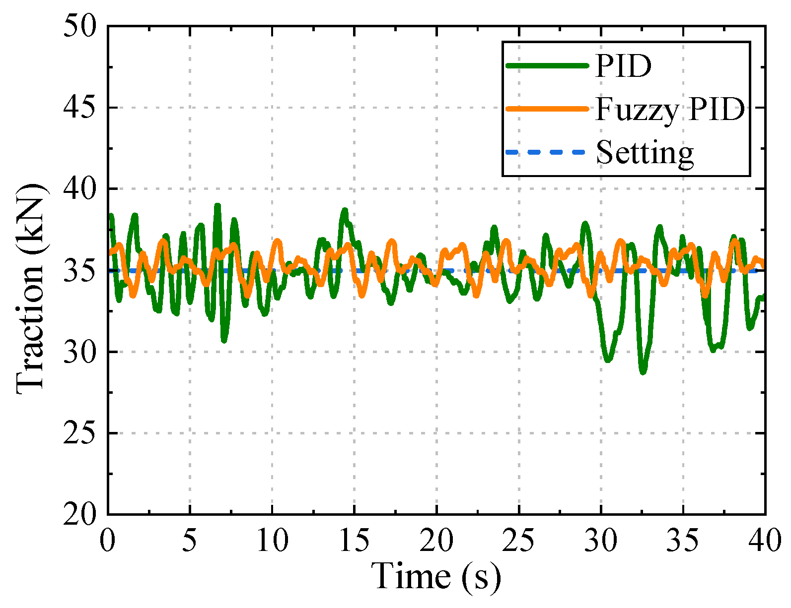
To evaluate the operating performance under the traction control mode, the target traction force is set at 35 kN, and comparative tests are carried out using the traditional PID control and fuzzy PID control, respectively. Figure 11 shows the traction control response curves. Both control algorithms can maintain the actual traction force near the set value, but there are significant differences in control accuracy and anti-disturbance capability.
When the traditional PID control is adopted, the actual traction force fluctuates continuously near the set value, with a fluctuation range of approximately 8 kN. This large-amplitude fluctuation reflects that when facing the rapid and random changes in the specific resistance of field soil, the PID controller with fixed parameters has difficulty adjusting the control gain in real time to effectively suppress disturbances, resulting in frequent oscillation of the traction force within a large range. The load stability coefficient under this working condition is: 90.6%. When the fuzzy PID control is adopted, the controller can optimize the PID parameters in real time according to the traction force deviation and its change rate, and quickly output the corresponding adjustment signal at the moment when the soil resistance changes abruptly, so that the traction force quickly returns to near the set value. During the entire operation process, the traction force fluctuation range is effectively controlled within 3 kN, and the load stability coefficient is 97.3%. This corresponds to an absolute increase of 6.7 percentage points and a relative improvement of 7.4%.
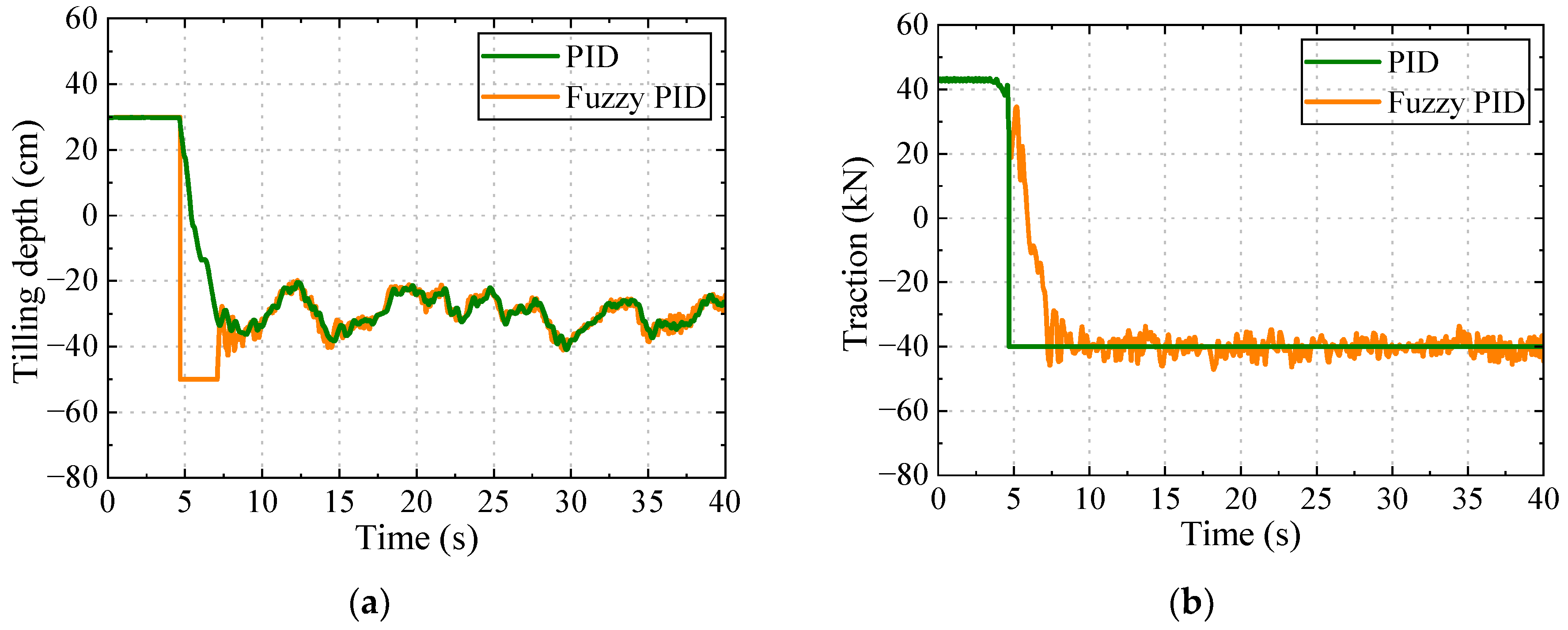
Figure 12 presents the test results of tillage depth and traction force under the traction-control mode with a target traction force of 40 kN. Under the traction-prioritized control strategy, the tillage depth is not maintained at a fixed set value but is dynamically adjusted according to variations in soil resistance to maintain the traction force near the target value. As shown in Figure 12a, when the soil resistance increases, the controller reduces the tillage depth to decrease the soil cutting resistance; conversely, when the soil resistance decreases, the tillage depth is increased to maintain the required traction force. For the PID controller, the average tillage depth was 30.5 cm, with a stability coefficient of 73.7%. In comparison, the Fuzzy PID controller yielded an average tillage depth of 29.5 cm with a stability coefficient of 96.1%, corresponding to an absolute increase of 22.4 percentage points in the tillage-depth stability coefficient.
The tillage-depth stability coefficient obtained with the fuzzy PID controller in the field test was 96.1%, which was close to the simulated value of 96.4%. This consistency provides additional evidence that the simulation model captured the dominant dynamics relevant to hitch control, while the field experiment further verified the effectiveness of the proposed controller under actual soil and load disturbances.
As shown in Figure 12b, both controllers maintained the traction force near the target value by dynamically adjusting the tillage depth to compensate for variations in soil resistance. The PID controller yielded an average traction force of 39.0 kN, corresponding to an absolute tracking error of 1.0 kN and a relative error of 2.5%. In contrast, the Fuzzy PID controller achieved an average traction force of approximately 40.0 kN with negligible steady-state tracking error. These results indicate that, compared with the traditional PID controller, the Fuzzy PID controller provides substantially improved tillage-depth stability and more accurate traction-force tracking under varying field soil resistance.
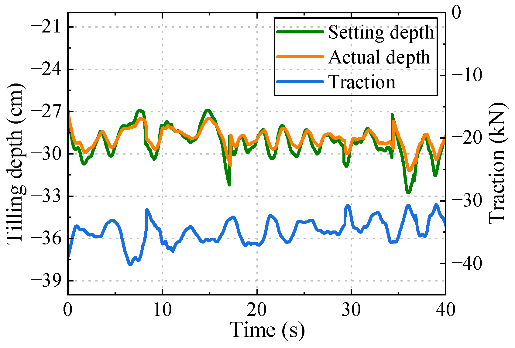
To evaluate the operational feasibility of the combined control strategy under field conditions, the prescribed tillage-depth and traction-force targets were set to 30 cm and 30 kN, respectively. In the combined control mode, the traction-force feedback was used to dynamically adjust the depth command. Field tests were conducted under these operating conditions, and the resulting tillage-depth and traction-force responses are shown in Figure 13. The varying depth-reference curve in Figure 13 does not represent a change in the prescribed initial tillage-depth target of 30 cm; rather, it represents the adjusted depth command generated by the combined control strategy in response to variations in traction force.
As shown in Figure 13, the actual tillage depth fluctuates around the prescribed target because the spatial variability of soil resistance causes continuous variations in the draft load. Under the combined control strategy, the average measured tillage depth was approximately 27.9 cm, corresponding to an absolute deviation of 2.1 cm and a relative deviation of approximately 7.0% from the prescribed target of 30 cm. The tillage-depth stability coefficient was 92.1%. The average traction force was 34.2 kN, corresponding to an absolute deviation of 4.2 kN and a relative deviation of approximately 14.0% from the prescribed target of 30 kN. The load stability coefficient was 89.1%. The larger relative deviation in traction force indicates that variations in soil resistance still affect the load-tracking performance of the system.
These results demonstrate that the combined control strategy can dynamically coordinate the tillage-depth command according to variations in traction force and maintain stable operation under variable field resistance. However, deviations from the prescribed targets remain, particularly for traction force. Therefore, in the absence of a baseline controller for direct comparison, the present results are interpreted as demonstrating the operational feasibility of the combined control strategy rather than its superiority over other control methods.

6. Conclusions

This paper presents a load-sensing electro-hydraulic implement hitch system based on digital hydraulic valves for high-horsepower tractors. A fuzzy PID-based depth control strategy is also proposed, which converts traction force setpoints into working depth setpoints through real-time estimation of soil-specific resistance. This approach unifies hitch regulation within a depth control framework, thereby improving operational precision. A multidisciplinary co-simulation model and an experimental test platform are developed to evaluate the system performance. Comprehensive tests, including dynamic response, depth control, traction control, and force-position combined control, are conducted through simulations and field operations.
The results demonstrate that the proposed system exhibits favorable dynamic characteristics and high tracking accuracy. In pure depth control and pure traction control modes, the depth stability coefficient and load stability coefficient are improved by 7.5% and 7.4%, respectively, compared with conventional PID control. Under force-position combined control with a weighting coefficient of 0.75, the depth stability coefficient reaches 92.1% and the load stability coefficient reaches 89.1%. These findings indicate that the proposed strategy achieves superior and balanced stability performance in both depth and load regulation.
Although the proposed fuzzy PID controller demonstrated improved performance compared with the conventional PID baseline, the present results should not be interpreted as demonstrating universal superiority over other advanced control methods. For example, sliding mode control can provide strong robustness against parameter uncertainties and external disturbances, but its practical implementation requires appropriate design of the sliding surface and switching law, together with measures to mitigate chattering. In contrast, the fuzzy PID strategy adopted in this study enables online adjustment of the controller gains without requiring an accurate model of the nonlinear soil–implement–tractor interaction, providing a relatively straightforward implementation for the investigated electro-hydraulic hitch system. Since sliding mode control and other advanced controllers were not implemented on the same experimental platform, a direct quantitative comparison cannot presently be made. Such comparisons under identical field conditions will be investigated in future work.

Author Contributions

Conceptualization, J.C. and Y.H.; methodology, Y.H.; software, W.L. and C.Z.; validation, M.L., J.C. and C.Z.; formal analysis, J.C.; investigation, W.L., J.C. and X.C.; resources, X.C. and Y.H.; data curation, M.L.; writing—original draft preparation, J.C.; writing—review and editing, C.Z. and W.L.; visualization, M.L.; supervision, X.C.; project administration, Y.H.; funding acquisition, Y.H. All authors have read and agreed to the published version of the manuscript.

Funding

This research was jointly funded by the National Key Research and Development Program Project, grant number 2022YFB3403005; the National Natural Science Foundation of China, grant number U25A20291; and the National Natural Science Youth Fund, grant number 52505069.

Data Availability Statement

The data presented in this study are available on request from the corresponding author.

Conflicts of Interest

The authors declare no conflicts of interest.

Abbreviations

The following abbreviations are used in this manuscript:
NBNegative Big
NMNegative Medium
NSNegative Small
PBPositive Big
PIDProportional Integral Derivative
PMPositive Medium
PSPositive Small
ZOZero

References

  1. Sun, X.; Lu, Z.; Song, Y.; Cheng, Z.; Jiang, C.; Qian, J.; Lu, Y. Development status and research progress of a tractor electro-hydraulic hitch system. Agriculture 2022, 12, 1547. [Google Scholar] [CrossRef] [Scilit]
  2. Sun, X.; Song, Y.; Lu, Z.; Deng, X. Research on a Coordinated Control Method of Tractor Electro Hydraulic Hitch Tillage Depth and Travel Speed Based on Optimal Overall Efficiency and Economic Performance. Agriculture 2025, 15, 2232. [Google Scholar] [CrossRef] [Scilit]
  3. Aravind, K.; Raja, P.; Manuel, P. Task-based agricultural mobile robots in arable farming: A review. Span. J. Agric. Res. 2017, 15, e0202. [Google Scholar] [CrossRef] [Scilit]
  4. Anche, G.M.; Devika, K.B.; Subramanian, S.C. Robust pitching disturbance force attenuation for tractor considering functional constraints. IEEE Access 2020, 8, 86419–86432. [Google Scholar] [CrossRef] [Scilit]
  5. Qin, S.; Zhang, S.; Zhong, W.; He, Z. Control algorithms for intelligent agriculture: Applications, challenges, and future directions. Processes 2025, 13, 3061. [Google Scholar] [CrossRef] [Scilit]
  6. Wang, L.; Wang, Y.; Dai, D.; Wang, X.; Wang, S. Review of electro-hydraulic hitch system control method of automated tractors. Int. J. Agric. Biol. Eng. 2021, 14, 1–11. [Google Scholar] [CrossRef] [Scilit]
  7. Sunusi, I.I.; Zhou, J.; Wang, Z.; Sun, C.; Eltayeb Ibrahim, I.E.; Opiyo, S.; Korohou, T.; Soomro, S.A.; Sale, N.A.; Olanrewaju, T.O. Intelligent tractors: Review of online traction control process. Comput. Electron. Agric. 2020, 170, 105176. [Google Scholar] [CrossRef] [Scilit]
  8. Liu, C.; Gu, J.; Du, X.; Liu, C.; Du, Y.; Mao, E. Differential and integral sliding mode adaptive control algorithm for draft and position integrated control of electro-hydraulic hitch in agricultural tractor. INMATEH Agric. Eng. 2023, 70, 369–378. [Google Scholar] [CrossRef] [Scilit]
  9. Wang, J.; Guo, H.; Deng, X. Deep Reinforcement Learning–Based Control Strategy for Electro-Hydrostatic Active Hitch. SAE Int. J. Passeng. Veh. Sys. 2025, 18, 243–265. [Google Scholar] [CrossRef] [Scilit]
  10. Šoštarić, M.; Burg, Z.; Jurić, I. Analysis of position control accuracy of tractor three-point hitch for seeding operations. Agronomy 2021, 11, 2218. [Google Scholar]
  11. Luo, Z.; Wang, J.; Wu, J.; Zhang, S.; Chen, Z.; Xie, B. Research on a hydraulic cylinder pressure control method for efficient traction operation in electro-hydraulic hitch system of electric tractors. Agriculture 2023, 13, 1555. [Google Scholar] [CrossRef] [Scilit]
  12. Lu, Z.; Guo, B.; Gao, Q. Study on auto-control method and experiment for tractor depth based on fuzzy control. Trans. Chin. Soc. Agric. Eng. 2013, 29, 23–29. [Google Scholar]
  13. Bietresato, M.; Caligiuri, C.; Mazzetti, F. Terrain-following performance analysis of floating mode for tractor-implement combinations. Machines 2024, 12, 168. [Google Scholar]
  14. Petrov, T.; Dimitrov, V. Experimental study of floating control mode of tractor three-point hitch system. Acta Technol. Agric. 2022, 25, 89–96. [Google Scholar]
  15. Zhang, M.; Li, Y.; Zhang, X. Weight-adjustable force-position composite control for heavy-duty tractor hitch system. IEEE Access 2023, 11, 48921–48932. [Google Scholar]
  16. Dai, D.; Zhang, J.; Zhang, B.; Li, P.; Hu, W. Adaptive hierarchical optimization control for electrohydraulic hitch with resistor-capacitor operator. Appl. Math. Model. 2024, 126, 606–624. [Google Scholar] [CrossRef] [Scilit]
  17. Liu, C.; Zhao, J.; Mao, E.R.; Gu, J.; Du, Y.; Li, Z.; Zhu, Z. Pressure control algorithm based on adaptive fuzzy PID with compensation correction for the tractor electronic hydraulic hitch. Appl. Sci. 2020, 10, 3179. [Google Scholar] [CrossRef] [Scilit]
  18. Zhang, W.; Yuan, Q.; Xu, Y.; Wang, X.; Bai, S.; Zhao, L.; Hua, Y.; Ma, X. Research on Control Strategy of Electro-Hydraulic Lifting System Based on AMESIM and MATLAB. Symmetry 2023, 15, 435. [Google Scholar] [CrossRef] [Scilit]
  19. Nikdel, N.; Kouhi, A. Mitigating tractor vibrations with a robust adaptive fractional controller: Design and Validation. Expert Syst. Appl. 2025, 275, 127119. [Google Scholar] [CrossRef] [Scilit]
  20. Li, J.; Du, X.; Li, D.; Jin, Y. Fractional order fuzzy backstepping adaptive controller for hydraulic hitch. Appl. Math. Model. 2026, 151, 116480. [Google Scholar] [CrossRef] [Scilit]
  21. Syromyatnikov, Y.; Khramov, N.; Voinash, S.; Partko, S.; Zagidullin, R. Work quality indicators tillage unit with application flexible working body in systems “Organic farming”. E3S Web Conf. 2023, 463, 01001. [Google Scholar] [CrossRef] [Scilit]
  22. Kuts, A.; Troyanovskaya, I.; Orekhovskaya, A.; Tikhonov, E.; Sokolova, V. Transporting ability calculation of the rotor of soil-cultivating loosening and separating vehicle. Acta Technol. Agric. 2022, 25, 73–78. [Google Scholar] [CrossRef] [Scilit]
  23. Xu, G.; Chen, M.; He, X.; Pang, H.; Miao, H.; Cui, P.; Wang, W.; Diao, P. Path following control of tractor with an electro-hydraulic coupling steering system: Layered multi-loop robust control architecture. Biosyst. Eng. 2021, 209, 282–299. [Google Scholar] [CrossRef] [Scilit]
  24. Shao, K.; Zheng, J.; Fu, M. Review on the developments of sliding function and adaptive gain in sliding mode control. J. Autom. Intell. 2025, 4, 266–272. [Google Scholar] [CrossRef] [Scilit]
  25. Miao, H.; Diao, P.; Yao, W.; Li, S.; Wang, W. Stability Study of Time Lag Disturbance in an Automatic Tractor Steering System Based on Sliding Mode Predictive Control. Agriculture 2022, 12, 2091. [Google Scholar] [CrossRef] [Scilit]
  26. Zhao, S.; Qu, G.; Liu, M.; Chen, X.; Gao, Z.; Xu, L. Research on Tractor Active Seat Hitch Based on Model Predictive Control. IEEE Access 2023, 11, 117078–117093. [Google Scholar] [CrossRef] [Scilit]
  27. Zhang, J.; Hou, J.; Liu, M.; Xu, L.; Wu, Y. Energy Efficient path tracking control for autonomous tractors equipped with Hydro Mechanical continuously variable transmission based on coordinated control methods. Comput. Electron. Agric. 2026, 237, 112115. [Google Scholar] [CrossRef] [Scilit]
  28. Xu, J.; Li, R.; Li, Y.; Zhang, Y.; Sun, H.; Ding, X.; Ma, Y. Research on Variable-Universe Fuzzy Control Technology of an Electro-Hydraulic Hitch System. Processes 2021, 9, 1920. [Google Scholar] [CrossRef] [Scilit]
  29. Xu, E.; Zhong, Q.; Pan, M.; Yan, X.; Miao, Y.; Yang, H. Novel Adaptive Sliding-Mode Control of Digital Hydraulic Systems with Nonlinear Flow Prediction and Friction Identification. Measurement 2025, 272, 118841. [Google Scholar] [CrossRef] [Scilit]
  30. Wu, Y.; Ruan, Y.; Zhang, J.; Wang, S.; Wang, L.; Du, X.; Yan, X. Dual-variable control load-sensing system for multi-way valves in hilly and mountainous tractors. PLoS ONE 2025, 20, e0321940. [Google Scholar] [CrossRef]
  31. Zhai, Z.; Chen, Y.; Zhu, S.; Du, Y.; Zhu, Z.; Mao, E. Experiment on Electro-hydraulic Hitch Control System for Hilly and Mountainous Tractor Based on Semi-physical Simulation. Trans. Chin. Soc. Agric. Mach. 2022, 53, 328–337. [Google Scholar]
  32. Coskun, M.Y.; Itik, M. Position control of a digital electrohydraulic system with limited sensory data using double deep q-network controller. Expert Syst. Appl. 2024, 252, 124275. [Google Scholar] [CrossRef] [Scilit]
  33. Glück, T.; Lobe, A.; Trachte, A.; Bitzer, M.; Kemmetmüller, W. Hybrid Control of Hydraulic Directional Valves: Integrating Physics-Based and Data-Driven Models for Enhanced Accuracy and Efficiency. Actuators 2024, 13, 452. [Google Scholar]
  34. Cheng, J.; Chi, R.; Lai, Q.; Yang, Y.; Mao, E. Active vibration control of tractor based on electro-hydraulic hitch system. Trans. Chin. Soc. Agric. Eng. 2017, 33, 82–90. [Google Scholar]
  35. Nguyen, T.H.; Do, T.C.; Ahn, K.K. A study on a new independent metering valve for hydraulic boom excavator. Appl. Sci. 2022, 12, 605. [Google Scholar] [CrossRef] [Scilit]
Figure 1. Hydraulic circuit of the tractor three-point electro-hydraulic hitch system.
Agriculture 16 02020 g001
Figure 2. Block diagram of control strategy for agricultural implement hitch electro-hydraulic system.
Agriculture 16 02020 g002
Figure 3. Block diagram of the PID control system for agricultural implement depth fuzzy control.
Agriculture 16 02020 g003
Figure 4. Co-simulation model of a high-horsepower tractor.
Agriculture 16 02020 g004
Figure 5. Relationship between tillage depth and angle sensor voltage of farm implements.
Agriculture 16 02020 g005
Figure 6. Simulation results of position step response characteristics of different control methods. (a) Tillage depth control characteristics. (b) Fractionated gain.
Agriculture 16 02020 g006
Figure 7. Simulation results of tillage depth control performance of different control schemes. (a) Soil work resistance. (b) Tillage depth control characteristics.
Agriculture 16 02020 g007
Figure 8. Test platform for hydraulic-electric system of large-horsepower tractor attachments and field cultivation test site.
Agriculture 16 02020 g008
Figure 9. Test curves of the hitch system under the step command signal.
Agriculture 16 02020 g009
Figure 10. Response curves of plowing depth control and the corresponding curve of traction force variation. (a) Tillage depth test curve. (b) Tractive force curve.
Agriculture 16 02020 g010
Figure 11. Test curves of furrow depth and traction force under traction control mode.
Agriculture 16 02020 g011
Figure 12. Test results of tillage depth and traction force under force control mode. (a) Tillage depth test curve. (b) Tractive force curve.
Agriculture 16 02020 g012
Figure 13. Test results of tillage depth and traction force under combined force-position control mode.
Agriculture 16 02020 g013
Table 1. Parameters of the fuzzy PID controller.
ParameterValueUnitParameterValueUnit
Base proportional gain0.20/Integral output scaling factor0.02/
Base integral gain0.05/Derivative output scaling factor0.004/
Base derivative gain0.010/Proportional output scaling
factor saturation range
[0.12, 0.28]/
Depth-error range[−40, 40]mmIntegral output scaling factor
saturation range
[0.03, 0.07]/
Error-rate range[−1000, 1000]mm/sDerivative output scaling factor
saturation range
[0.006, 0.014]/
Normalized input universe[−6, 6]/Controller output saturation[−10, 10]V
Error scaling factor0.15mm−1Sampling period0.01s
Proportional output scaling factor0.08/Fuzzy update period0.01s
Table 2. Fuzzy control rules of tillage depth.
e H e c
NBNMNSZOPSPMPB
NBPM/NB/PBPS/NM/PMZO/NS/PSNS/ZO/ZONM/PS/NSNB/PM/NMNB/PB/NB
NMPS/NM/PMPS/NS/PMZO/ZO/PSNS/PS/ZONM/PS/NSNB/PM/NMNB/PB/NB
NSPS/NS/PMZO/ZO/PSNS/ZO/ZONM/PS/NSNB/PM/NMNB/PB/NBNM/PB/NB
ZOZO/ZO/PSNS/ZO/ZONM/PS/NSNB/PM/NMNM/PM/NBNS/PB/NMZO/PB/NS
PSNS/ZO/ZONM/PS/NSNB/PS/NMNB/PM/NBNM/PB/NBNS/PB/NMZO/PB/NS
PMNM/PS/NSNB/PS/NMNB/PM/NBNM/PB/NBNS/PB/NMZO/PB/NSPS/PB/ZO
PBNB/PS/NMNB/PM/NBNM/PB/NBNS/PB/NMZO/PB/NSPS/PB/ZOPS/PB/PS
Table 3. Key parameters of the SimulationX model.
ParameterValueUnitParameterValueUnit
Pump displacement45ml/rFive-furrow plow mass1200kg
Load-sensing pressure margin1.8MPaCylinder stroke200mm
Effective oil bulk modulus1.4GPaGravitational load of
implement
11.77kN
Valve discharge coefficient0.62/Sensor calibration gain29.92mm/V
Cylinder piston-side
effective area
7.85 × 10⁻³m2Cylinder rod-side
effective area
6.13 × 10⁻³m2
Disclaimer/Publisher’s Note: The statements, opinions and data contained in all publications are solely those of the individual author(s) and contributor(s) and not of MDPI and/or the editor(s). MDPI and/or the editor(s) disclaim responsibility for any injury to people or property resulting from any ideas, methods, instructions or products referred to in the content.