2.1.1. Mathematical Model for Simulation
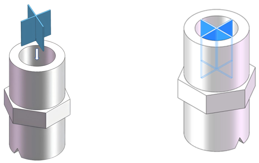
To minimize the flow distortion induced by the L-shaped elbow, a flat-fan nozzle with built-in flow-straightening vanes was designed based on the conventional flat-fan nozzle structure, as shown in
Figure 1. The main feature of this design is the integration of flow-straightening vanes within the internal flow passage of the nozzle. These vanes form a compact internal flow rectifier to promote flow guidance and stabilization. The structure regulates the flow field within the confined interior of the flat-fan nozzle by weakening swirl-dominated and asymmetric flow components and promoting a more uniform axial flow before the liquid reaches the orifice. The flow-straightening vanes are uniformly arranged in the circumferential direction and divide the flow passage from the nozzle inlet to the contraction section into several sector-shaped flow-straightening zones. The vanes extend axially, with their leading ends positioned near the nozzle inlet and their trailing ends extending toward the contraction zone near the V-shaped notch. Through flow division, guidance, and rectification of the elbow-induced distorted flow, the design aims to improve the internal flow field without requiring an additional long straight pipe section upstream of the nozzle.
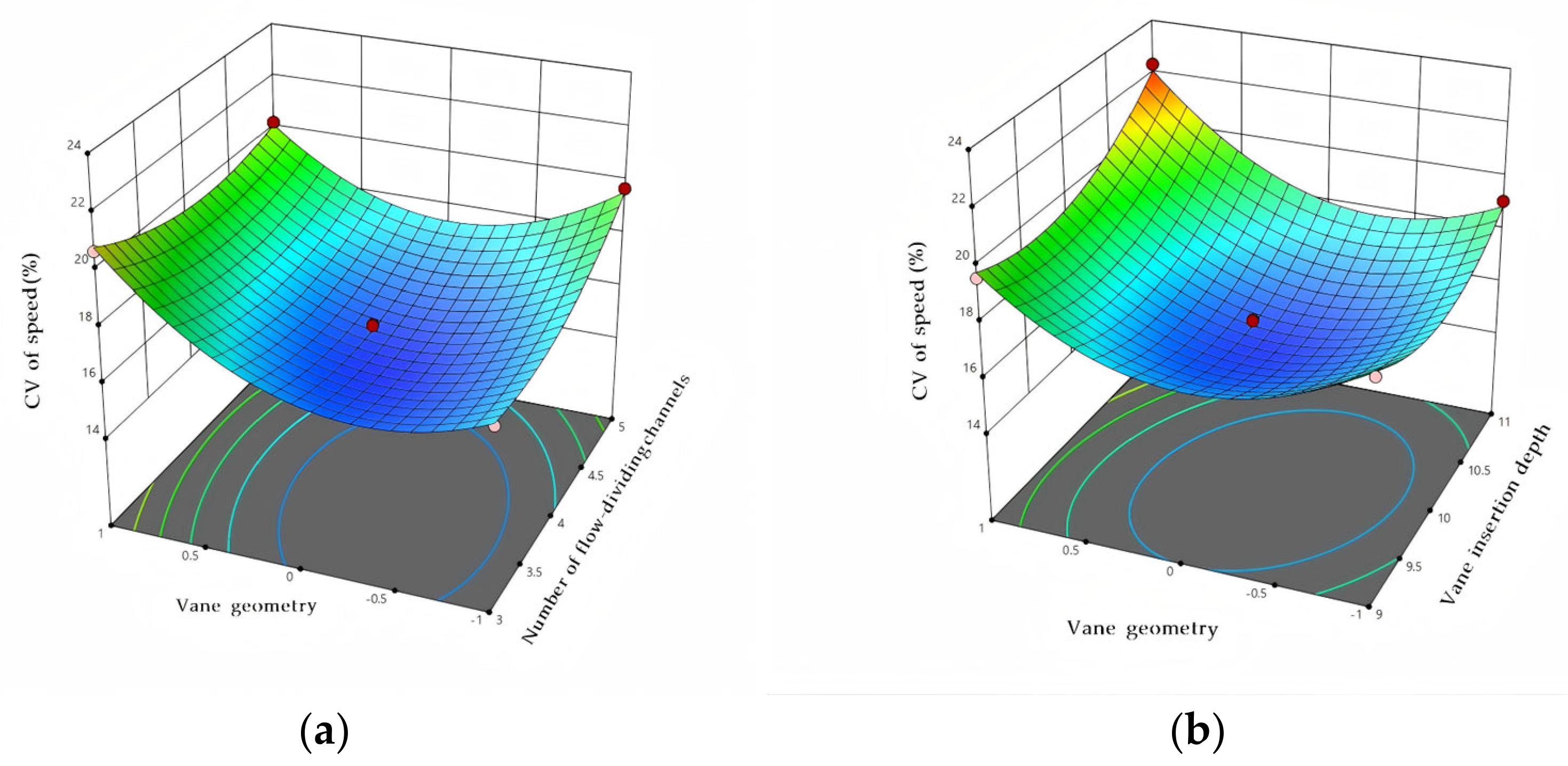
The design rationale of the flow-straightening structure is to mitigate elbow-induced inlet-flow distortion before the liquid reaches the V-shaped orifice. The flat-fan flow-straightening nozzle designed in this study was intended for operation under L-shaped elbow connection conditions. The L-shaped elbow upstream of the nozzle produces a non-axisymmetric inlet velocity profile, secondary flow, and transverse momentum, which may propagate into the internal passage of the nozzle and disturb the formation of the fan-shaped spray. Therefore, a built-in vane structure was integrated into the nozzle interior to reduce these disturbances before the liquid reaches the V-shaped orifice. The number of flow-dividing channels determines the scale of flow subdivision. Increasing the channel number decreases the characteristic width of each substream and weakens large-scale transverse circulation; however, excessive subdivision increases the wetted wall area, viscous loss, and blockage risk. Therefore, 1–5 channels were selected for the single-factor study, and 3–5 channels were used in the response surface optimization after excluding the obviously less effective end cases. Vane geometry affects the balance between rectification and additional disturbance. A star-shaped vane provides circumferentially balanced sector passages and direct axial guidance; a multi-plate vane provides simple planar guidance but may lead to incomplete recombination of substreams; a projectile-tail-shaped vane introduces a central core passage and can improve central flow continuity but may reduce the spray angle; a helical vane was included to evaluate whether curved guidance could mitigate swirl, although it may also introduce tangential momentum; and a segmented vane was included to assess multi-stage rectification, which may generate local separation at segment joints. Vane insertion depth determines the axial length available for flow recovery. A short insertion depth may not provide sufficient development length for rectification, whereas an excessive insertion depth increases hydraulic resistance and local wall-induced disturbance.
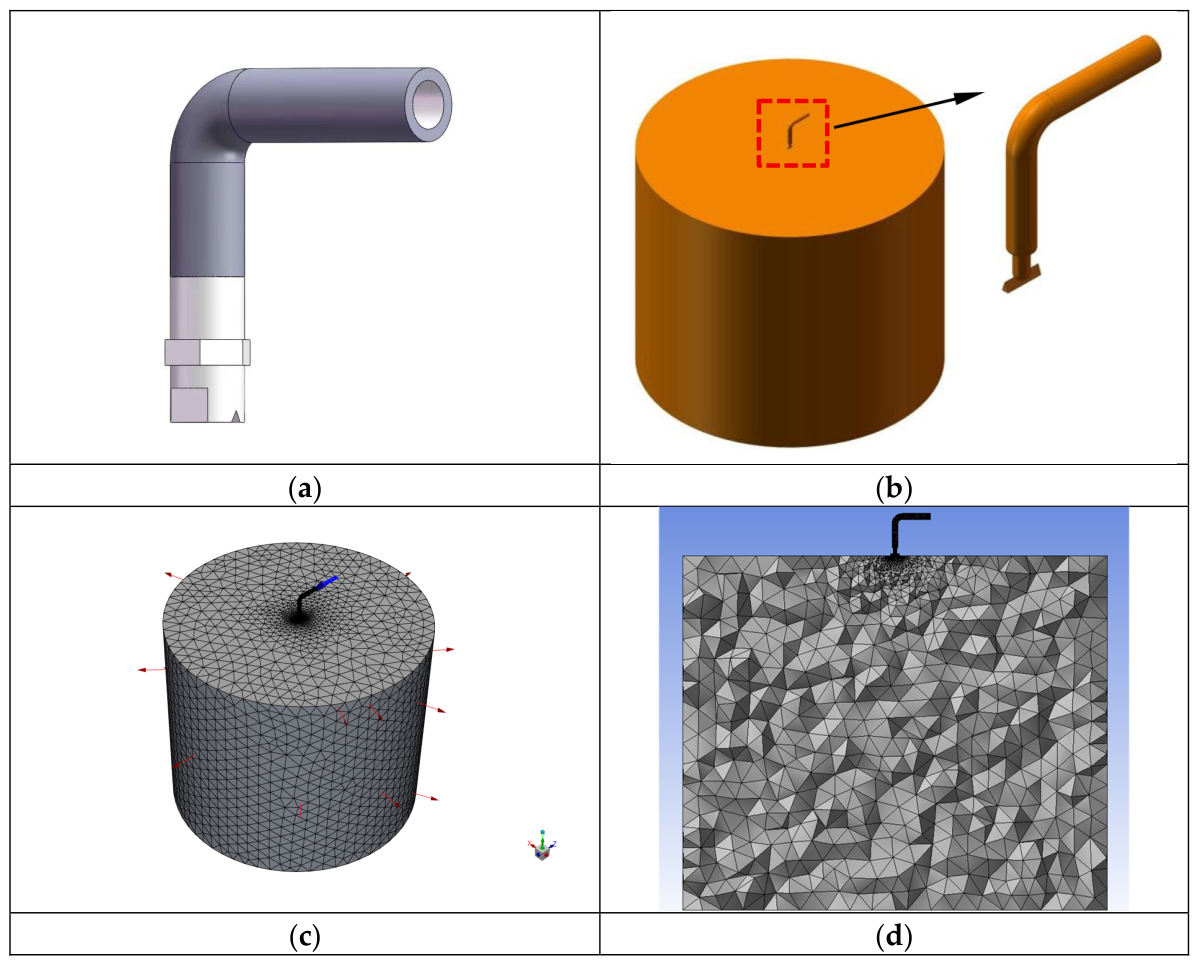
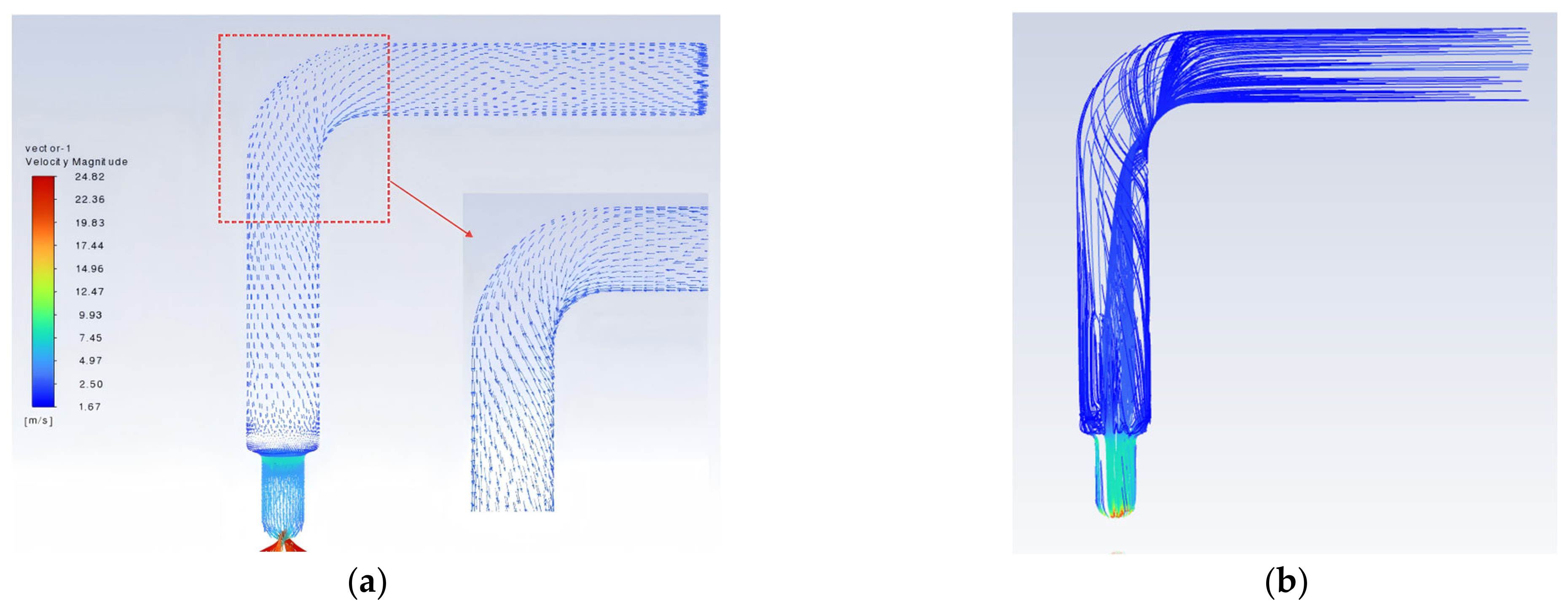
Based on the above design rationale, a three-dimensional model of the “L-shaped elbow-flat-fan flow-straightening nozzle” assembly was established in SOLIDWORKS (2018), as shown in
Figure 2a. The grey component represents the L-shaped elbow, and the lower component represents the connected flat-fan flow-straightening nozzle. The model was then imported into ANSYS SpaceClaim 2022 R1 for fluid-domain extraction, and the resulting computational domain is shown in
Figure 2b. The external flow-field domain had dimensions of Φ600 mm × 500 mm. The computational model was subsequently imported into ANSYS Meshing for mesh generation. Because the nozzle was relatively small compared with the external flow-field domain, a polyhedral mesh was applied in the nozzle region to improve the resolution of the internal and near-orifice jet flow fields, with local refinement near the nozzle outlet. After meshing, the entire region was defined as the fluid domain. The inlet end of the L-shaped elbow was designated as the inlet, the outer boundary of the cylindrical external flow-field domain was designated as the outlet, and all remaining boundaries were defined as walls. The mesh model is presented in
Figure 2c,d, and the detailed simulation parameter settings are listed in
Table 1.
A turbulence-model sensitivity study was performed using the standard k–ε, RNG k–ε, and SST k–ω models. Considering the substantial computational cost of the transient VOF simulations, the sensitivity analysis was performed for the representative optimized configuration, consisting of a star-shaped vane, four flow-dividing channels, and a vane insertion depth of 10 mm, at an operating pressure of 0.30 MPa. The geometry, computational mesh, material properties, VOF settings, boundary conditions, numerical schemes, time step, convergence criteria, and data-extraction procedure were kept identical among the three simulations. Only the turbulence model was changed.
The normal-velocity coefficient of variation at the evaluation plane located 400 mm downstream of the nozzle, mean normal velocity, and water volumetric flow rate were compared. The results are presented in
Table 2.
Taking the RNG k–ε model as the reference, the standard k–ε model predicted a 19.91% higher normal-velocity CV, a 16.79% higher mean normal velocity, and a 14.12% higher volumetric flow rate. The corresponding differences predicted by the SST k–ω model were 6.02%, 7.28%, and 3.53%, respectively. The relative ranges among the three models were 18.33% for the normal-velocity CV, 15.54% for the mean normal velocity, and 13.33% for the volumetric flow rate. The mean normal velocity and volumetric flow rate exhibited a consistent variation among the models: the standard k–ε model predicted the highest values, the RNG k–ε model predicted the lowest values, and the SST k–ω predictions were intermediate.
To assess the numerical uncertainties of the present CFD approach, two sensitivity studies were performed for the representative optimized configuration (star-shaped vane, four flow-dividing channels, 10 mm insertion depth, 0.30 MPa): mesh independence and turbulence-model selection. For the mesh study, four tetrahedral meshes were generated using the patch-conforming method with varying proximity gap factors, yielding cell counts of 15,693, 27,794, 35,594, and 39,016. This refinement strategy increased the mesh resolution near the elbow–nozzle connection, vane passages, V-shaped orifice, and nozzle outlet, where strong velocity gradients and air–water interface deformation were expected.
The normal-velocity coefficient of variation at the evaluation plane located 400 mm downstream of the nozzle was selected as the principal mesh-sensitivity indicator because it was also the primary response used in the structural optimization. The results are summarized in
Table 3.
The corresponding normal-velocity coefficients of variation at the evaluation plane located 400 mm downstream of the nozzle were 19.12%, 17.05%, 16.34%, and 16.22%, respectively. Increasing the number of cells from 35,594 to 39,016, corresponding to a 9.61% increase in cell number, reduced the normal-velocity CV by only 0.12 percentage points, equivalent to a relative difference of 0.74%. Because this difference was below the adopted mesh-sensitivity criterion of 2%, further refinement was considered to have no material effect on the principal optimization response. Therefore, the mesh containing 35,594 tetrahedral cells was selected for the subsequent parametric simulations and response-surface optimization. The mesh-quality indicators were also reported: maximum skewness = 0.82, average skewness = 0.21, minimum orthogonal quality = 0.24. The near-wall region was treated using standard wall functions.
2.1.2. Configurations of the Flat-Fan Flow-Straightening Nozzle
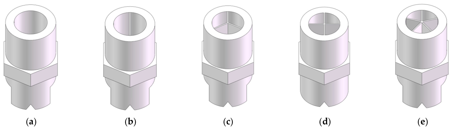
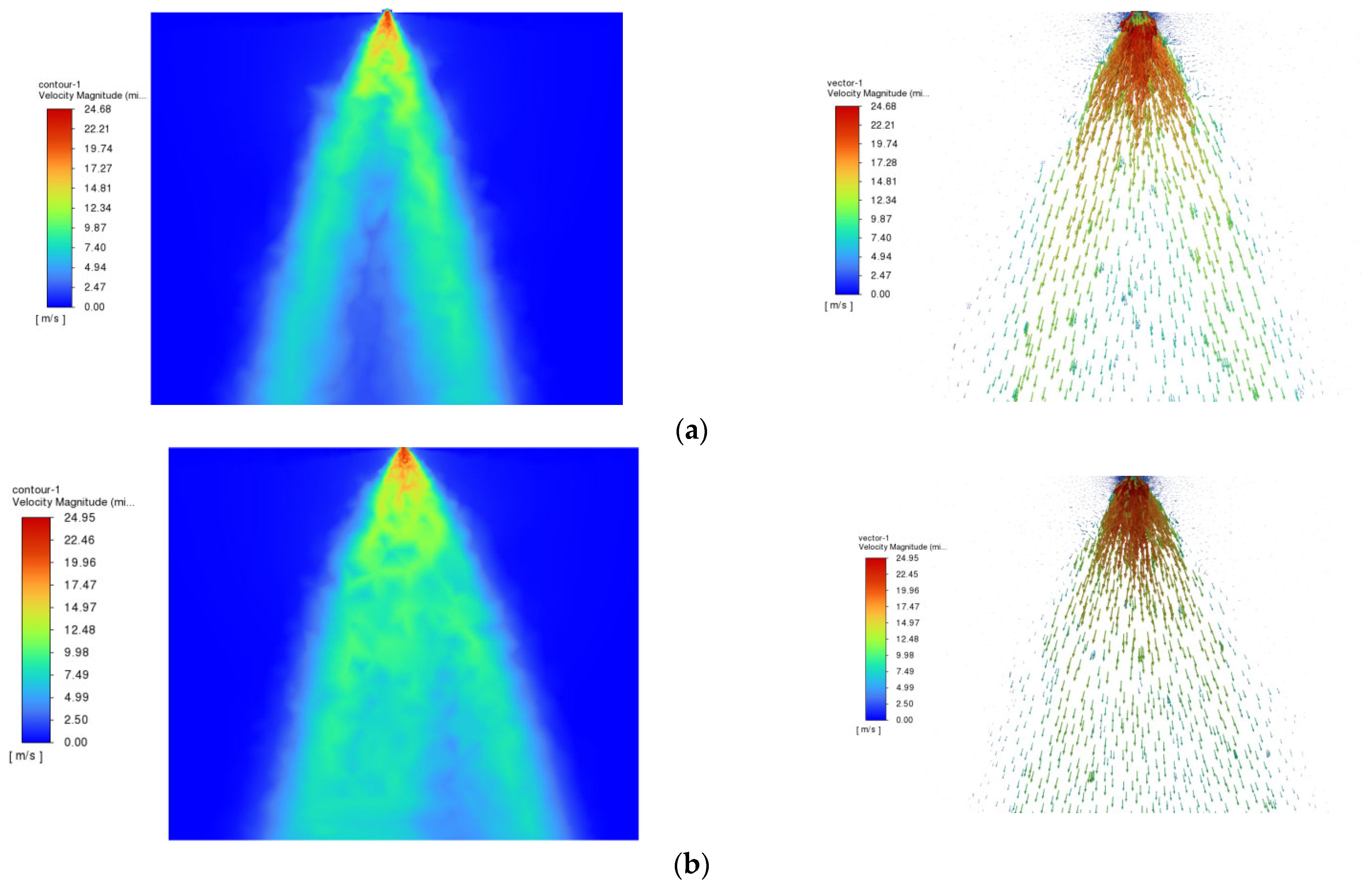
In the single-factor simulations investigating the effect of the number of flow-dividing channels on the flow field and performance of the flat-fan flow-straightening nozzle, the design concept for mitigating the influence of the L-shaped elbow-induced incoming flow on the fan-shaped spray pattern was as follows: the irregular bulk flow was first divided into several small streams, which were then rectified and recombined into a regular, uniform flow, thereby achieving the desired flow stabilization. Five levels of the number of flow-dividing channels, namely {1, 2, 3, 4, 5}, were selected as the test factor. In the experimental design, the vane insertion depth was set to 10 mm by default, and the vane geometry was set to the star-shaped type by default, as shown in
Figure 3.
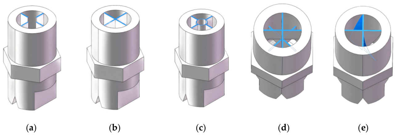
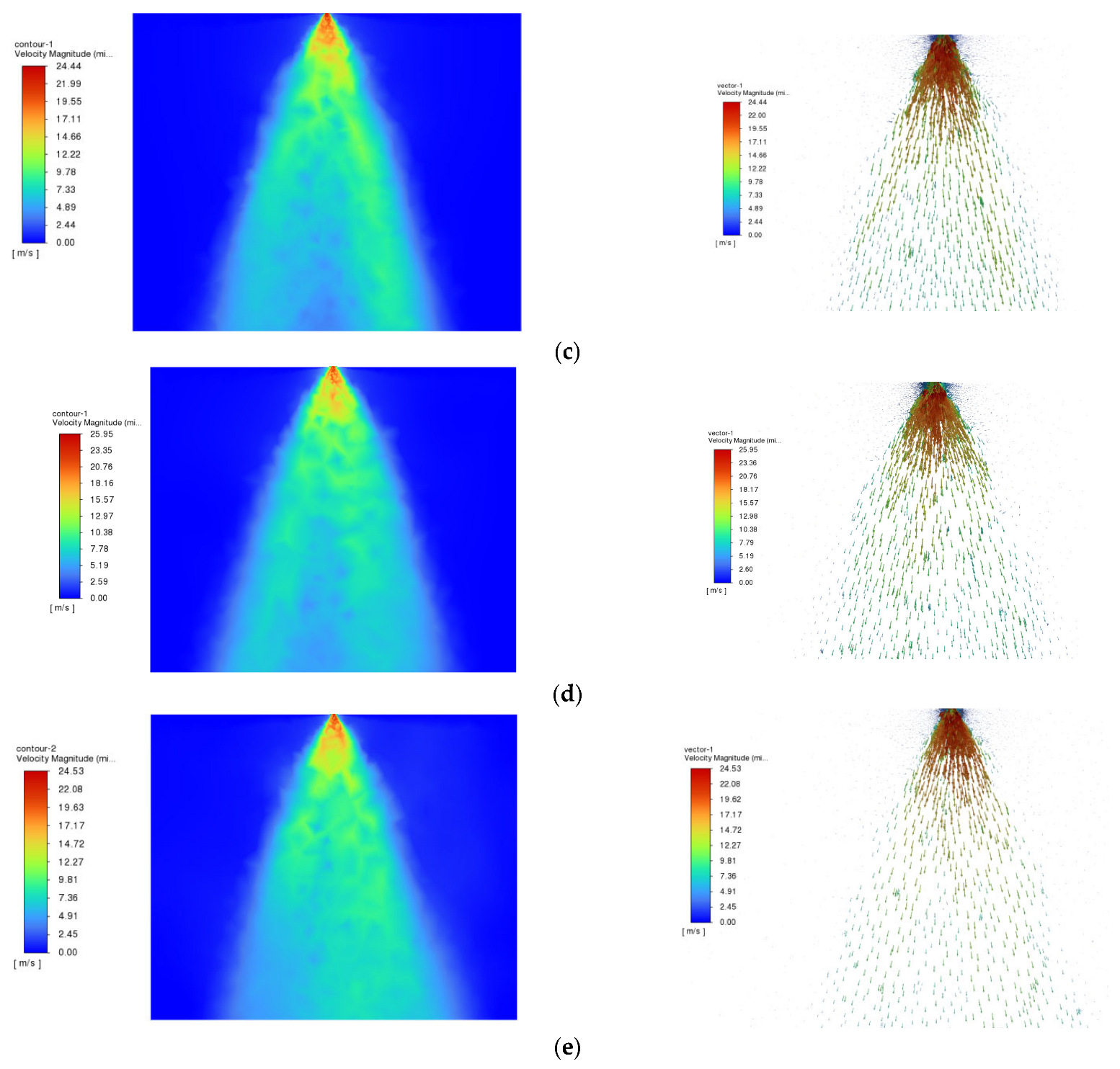
In the single-factor simulations investigating the effect of vane geometry on the flow field and performance of the flat-fan flow-straightening nozzle, five vane geometries were selected as the test factor: star-shaped, multi-plate, projectile-tail-shaped, helical, and segmented. In the experimental design, the vane insertion depth was set to 10 mm by default, and the number of flow-dividing channels was set to four by default, as shown in
Figure 4. Different vane geometries have varying capabilities in mitigating inlet flow deflection, transverse momentum, and secondary flows, all of which consequently affect the symmetry, continuity, and uniformity of the outlet fan-shaped velocity field. For the helical vane shown in
Figure 4e, the total twist angle was set to 45° over an axial insertion depth of 10 mm, and the mean diameter of the helical guide path was 8.6 mm, the equivalent helical pitch was 80 mm. Based on these parameters, the helix angle was 71.4°, corresponding to 18.6° when defined relative to the nozzle axis. Since the helical vane was evaluated as a comparative vane geometry rather than selected as the final optimized structure, the total twist angle, insertion depth, mean diameter, equivalent pitch, and helix angle were used as its main geometric descriptors.
In the single-factor simulations investigating the effect of vane insertion depth on the flow field and performance of the flat-fan flow-straightening nozzle, five levels of vane insertion depth, namely {8, 9, 10, 11, 12 mm}, were selected as the test factor. In the experimental design, the number of flow-dividing channels was set to four by default, and the vane geometry was set to the star-shaped type by default. The vane insertion depth, defined as the axial length occupied by the vanes within the nozzle interior, alters the length of the flow-straightening zone inside the fan nozzle, thereby affecting the degree to which the irregular and complex flow induced by the L-shaped elbow is divided, rectified, and stabilized within the nozzle.