Article

Flow-Field Performance Analysis of a Flat-Fan Flow-Straightening Nozzle

1
College of Agricultural Equipment and Energy Engineering, Northeast Agricultural University, Harbin 150030, China
2
Shaanxi Aircraft Industry Co., Ltd., Hanzhong 723000, China
3
College of Life Sciences, Northeast Agricultural University, Harbin 150030, China
4
College of Agricultural Equipment, Heilongjiang Agricultural Engineering Vocational and Technical University, Harbin 150088, China
*
Author to whom correspondence should be addressed.
Agriculture 2026, 16(17), 1827; https://doi.org/10.3390/agriculture16171827
Submission received: 6 July 2026 / Revised: 18 August 2026 / Accepted: 24 August 2026 / Published: 26 August 2026
(This article belongs to the Section Agricultural Technology)

Abstract

Flow distortion generated by L-shaped elbows in plant-protection spraying equipment disturbs the inlet flow of flat-fan nozzles, causing non-uniform outlet velocity distributions and reduced foliar deposition uniformity. This study developed a flat-fan nozzle with built-in flow-straightening vanes to improve spray stability under complex pipeline conditions. A three-dimensional CFD model integrating an L-shaped elbow, nozzle, and external spray region was established, and the Volume of Fluid (VOF) model was used to examine the effects of flow-dividing channel number, vane geometry, and vane insertion depth on velocity distribution on the spray fan plane. Structural parameters were optimized using a Box–Behnken response surface design. Field experiments on soybean seedlings evaluated droplet deposition using a carmine tracer assay with microplate reader measurement. The built-in vanes reduced elbow-induced flow deflection, swirl, and localized high-velocity zones, thereby improving spray fan velocity uniformity. The influence on the coefficient of variation of normal velocity followed the order: vane geometry > insertion depth > channel number. The optimal configuration comprised four channels, a star-shaped vane, and a 10 mm insertion depth, yielding a normal-velocity coefficient of variation of 16.12% at 400 mm downstream of the nozzle. Field trials showed that the developed nozzle reduced droplet deposition CV from 4.46% to 2.03% compared with the conventional flat-fan nozzle, a 54.5% decrease, with a significant difference between nozzles (p = 0.006). These results indicate that built-in flow-straightening vanes can improve spray stability and foliar deposition uniformity under elbow-induced flow distortion.

1. Introduction

Spray application is an important approach for the precise delivery of pesticides, liquid fertilizers, and functional additives in agricultural plant-protection operations. Spray quality directly affects target deposition uniformity, pesticide-use efficiency, and the risk of environmental drift [1,2]. Chen et al. reported that droplet size parameters affect deposition and drift in aerial spraying, highlighting the importance of spray quality for biological performance [1]. As the terminal component of a spray system, the nozzle plays a decisive role in atomization, spray pattern formation, velocity distribution, and droplet deposition characteristics [3,4,5]. Among different nozzle types, flat-fan nozzles are widely used in boom sprayers and field spraying equipment because of their broad spray coverage, simple structure, and adaptability. Kluza et al. modeled spray coverage uniformity of flat-fan nozzles, emphasizing the role of nozzle structure in distribution symmetry [6]. Under ideal conditions, the liquid entering the nozzle should maintain a stable and uniform flow state, allowing a continuous and symmetrical fan-shaped liquid film to form at the orifice and thereby ensuring uniform spray distribution and target deposition [7,8].
However, in practical agricultural spraying equipment, the upstream flow conditions of nozzles are often non-ideal. Owing to the compact structure of spray booms, frame space limitations, nozzle mounting angles, and pipeline layout constraints, nozzles are frequently connected to the main pipeline through elbows, short connectors, or other non-straight fittings. Abuhatira et al. and Rohrig et al. analyzed elbow flow distortion in pipe systems, demonstrating that curved inlets generate secondary flow and velocity-profile asymmetry [9,10]. As a result, it is often difficult to provide a sufficiently long straight pipe section upstream of the nozzle. When liquid flows through an L-shaped elbow, the main flow direction changes abruptly [11,12]. Under the combined effects of inertial forces and wall viscosity, radial pressure gradients, secondary flows, local flow separation, and distorted velocity profiles can be generated. Such non-uniform inlet flow can propagate through the internal flow passage of the nozzle to the orifice outlet, resulting in spray fan deflection, localized high-velocity regions, and uneven transverse velocity distribution, which may ultimately reduce droplet deposition uniformity [13].
Previous studies have evaluated spray quality mainly in terms of nozzle structure, spray pressure, application height, nozzle spacing, droplet size, and deposition characteristics [14,15,16,17,18,19,20]. These studies have shown that internal nozzle flow and inlet boundary conditions significantly affect spray pattern formation [7,21,22]. Nevertheless, the coupling relationship between upstream elbow-induced flow distortion and the spray fan uniformity of flat-fan nozzles remains insufficiently understood in agricultural nozzle research. In particular, under complex pipeline connection conditions, it remains necessary to clarify how compact internal nozzle structures can mitigate inlet flow deflection and swirling flow, and whether such flow regulation can further improve foliar droplet deposition uniformity under field conditions.
Current technical solutions for improving spray quality can be broadly divided into nozzle-based, operating-parameter-based, and pipeline-flow-conditioning approaches. Nozzle-based solutions, such as conventional flat-fan nozzles [23], air-induction nozzles, drift-reducing nozzles, and twin flat-fan nozzles [24], mainly regulate spray angle, droplet spectrum, and swath overlap. These approaches are effective for controlling droplet size and reducing drift, but they generally do not directly correct inlet-flow distortion generated by upstream elbows or short connectors. Operating-parameter optimization, including spray pressure [25,26], boom height, travel speed, nozzle spacing, and carrier volume, can improve deposition and reduce drift under specified field conditions; however, the optimized performance is sensitive to the installation layout and environmental conditions. In engineering flow systems, distorted inlet velocity profiles are commonly reduced by increasing the upstream straight-pipe length [27] or by installing flow conditioners such as perforated plates, tube bundles, or guide vanes [28,29,30]. These solutions can improve velocity-profile recovery but require additional space, increase hydraulic resistance, and complicate installation and maintenance. For compact plant-protection spray booms, these constraints make it difficult to apply external flow-conditioning devices near each nozzle. Therefore, integrating a compact flow-straightening structure inside the flat-fan nozzle is a practical route for mitigating elbow-induced flow asymmetry without changing the external mounting configuration.
Computational fluid dynamics (CFD) provides an effective tool for revealing complex flow characteristics inside nozzles and in the near-orifice region [31,32,33,34]. Yan et al. further showed that CFD can be used to predict spray droplet deposition characteristics and validate them experimentally [35]. Compare with experimental measurements alone, CFD can provide detailed information on the internal velocity field, pressure field, turbulence characteristics, and velocity distribution on the spray fan plane. It is therefore suitable for analyzing the effects of elbow-induced flow distortion on the spray performance of flat-fan nozzles. Moreover, when combined with response surface methodology, CFD can be used to quantitatively evaluate the effects of multiple structural factors and their interactions on spray uniformity, thereby improving the efficiency of structural optimization [36,37,38,39]. The Box–Behnken design is a commonly used response surface design method and is suitable for multi-factor and multi-level optimization of structural parameters.
Based on these considerations, this study developed a flat-fan nozzle with built-in flow-straightening vanes to address the non-uniform outlet velocity distribution and reduced droplet deposition stability of flat-fan nozzles under L-shaped elbow connection conditions. The working hypothesis was that built-in flow-straightening vanes could mitigate elbow-induced flow deflection and swirling flow, improve the velocity uniformity on the spray fan plane, and consequently enhance foliar droplet deposition uniformity in field crops. To test this hypothesis, a three-dimensional CFD model integrating the L-shaped elbow, flat-fan nozzle, and external spray region was established to analyze the effects of the number of flow-dividing channels, vane geometry, and vane insertion depth on the coefficient of variation of normal velocity on the spray plane. Subsequently, a Box–Behnken response surface design was used to optimize the key structural parameters. Finally, field spraying experiments on soybean seedlings were conducted, and droplet deposition uniformity was evaluated using a carmine tracer assay coupled with microplate reader measurements to compare the conventional flat-fan nozzle with the developed flow-straightening nozzle. The results are expected to provide a reference for the structural optimization of agricultural nozzles and the design of high-uniformity spraying systems under complex pipeline layout conditions.

2. Materials and Methods

2.1. Simulation

2.1.1. Mathematical Model for Simulation

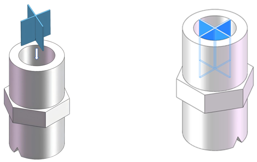
To minimize the flow distortion induced by the L-shaped elbow, a flat-fan nozzle with built-in flow-straightening vanes was designed based on the conventional flat-fan nozzle structure, as shown in Figure 1. The main feature of this design is the integration of flow-straightening vanes within the internal flow passage of the nozzle. These vanes form a compact internal flow rectifier to promote flow guidance and stabilization. The structure regulates the flow field within the confined interior of the flat-fan nozzle by weakening swirl-dominated and asymmetric flow components and promoting a more uniform axial flow before the liquid reaches the orifice. The flow-straightening vanes are uniformly arranged in the circumferential direction and divide the flow passage from the nozzle inlet to the contraction section into several sector-shaped flow-straightening zones. The vanes extend axially, with their leading ends positioned near the nozzle inlet and their trailing ends extending toward the contraction zone near the V-shaped notch. Through flow division, guidance, and rectification of the elbow-induced distorted flow, the design aims to improve the internal flow field without requiring an additional long straight pipe section upstream of the nozzle.
The design rationale of the flow-straightening structure is to mitigate elbow-induced inlet-flow distortion before the liquid reaches the V-shaped orifice. The flat-fan flow-straightening nozzle designed in this study was intended for operation under L-shaped elbow connection conditions. The L-shaped elbow upstream of the nozzle produces a non-axisymmetric inlet velocity profile, secondary flow, and transverse momentum, which may propagate into the internal passage of the nozzle and disturb the formation of the fan-shaped spray. Therefore, a built-in vane structure was integrated into the nozzle interior to reduce these disturbances before the liquid reaches the V-shaped orifice. The number of flow-dividing channels determines the scale of flow subdivision. Increasing the channel number decreases the characteristic width of each substream and weakens large-scale transverse circulation; however, excessive subdivision increases the wetted wall area, viscous loss, and blockage risk. Therefore, 1–5 channels were selected for the single-factor study, and 3–5 channels were used in the response surface optimization after excluding the obviously less effective end cases. Vane geometry affects the balance between rectification and additional disturbance. A star-shaped vane provides circumferentially balanced sector passages and direct axial guidance; a multi-plate vane provides simple planar guidance but may lead to incomplete recombination of substreams; a projectile-tail-shaped vane introduces a central core passage and can improve central flow continuity but may reduce the spray angle; a helical vane was included to evaluate whether curved guidance could mitigate swirl, although it may also introduce tangential momentum; and a segmented vane was included to assess multi-stage rectification, which may generate local separation at segment joints. Vane insertion depth determines the axial length available for flow recovery. A short insertion depth may not provide sufficient development length for rectification, whereas an excessive insertion depth increases hydraulic resistance and local wall-induced disturbance.
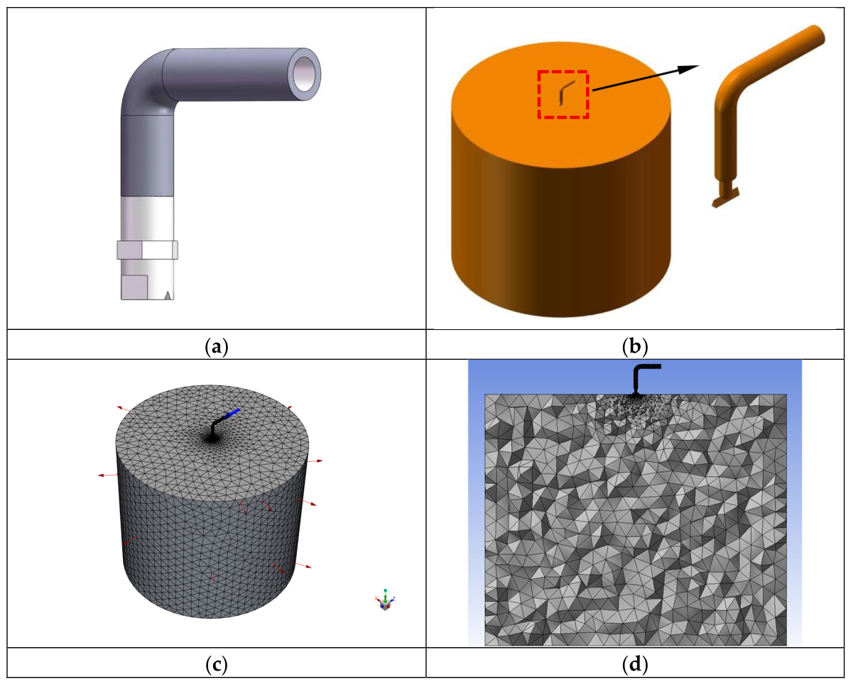
Based on the above design rationale, a three-dimensional model of the “L-shaped elbow-flat-fan flow-straightening nozzle” assembly was established in SOLIDWORKS (2018), as shown in Figure 2a. The grey component represents the L-shaped elbow, and the lower component represents the connected flat-fan flow-straightening nozzle. The model was then imported into ANSYS SpaceClaim 2022 R1 for fluid-domain extraction, and the resulting computational domain is shown in Figure 2b. The external flow-field domain had dimensions of Φ600 mm × 500 mm. The computational model was subsequently imported into ANSYS Meshing for mesh generation. Because the nozzle was relatively small compared with the external flow-field domain, a polyhedral mesh was applied in the nozzle region to improve the resolution of the internal and near-orifice jet flow fields, with local refinement near the nozzle outlet. After meshing, the entire region was defined as the fluid domain. The inlet end of the L-shaped elbow was designated as the inlet, the outer boundary of the cylindrical external flow-field domain was designated as the outlet, and all remaining boundaries were defined as walls. The mesh model is presented in Figure 2c,d, and the detailed simulation parameter settings are listed in Table 1.
A turbulence-model sensitivity study was performed using the standard k–ε, RNG k–ε, and SST k–ω models. Considering the substantial computational cost of the transient VOF simulations, the sensitivity analysis was performed for the representative optimized configuration, consisting of a star-shaped vane, four flow-dividing channels, and a vane insertion depth of 10 mm, at an operating pressure of 0.30 MPa. The geometry, computational mesh, material properties, VOF settings, boundary conditions, numerical schemes, time step, convergence criteria, and data-extraction procedure were kept identical among the three simulations. Only the turbulence model was changed.
The normal-velocity coefficient of variation at the evaluation plane located 400 mm downstream of the nozzle, mean normal velocity, and water volumetric flow rate were compared. The results are presented in Table 2.
Taking the RNG k–ε model as the reference, the standard k–ε model predicted a 19.91% higher normal-velocity CV, a 16.79% higher mean normal velocity, and a 14.12% higher volumetric flow rate. The corresponding differences predicted by the SST k–ω model were 6.02%, 7.28%, and 3.53%, respectively. The relative ranges among the three models were 18.33% for the normal-velocity CV, 15.54% for the mean normal velocity, and 13.33% for the volumetric flow rate. The mean normal velocity and volumetric flow rate exhibited a consistent variation among the models: the standard k–ε model predicted the highest values, the RNG k–ε model predicted the lowest values, and the SST k–ω predictions were intermediate.
To assess the numerical uncertainties of the present CFD approach, two sensitivity studies were performed for the representative optimized configuration (star-shaped vane, four flow-dividing channels, 10 mm insertion depth, 0.30 MPa): mesh independence and turbulence-model selection. For the mesh study, four tetrahedral meshes were generated using the patch-conforming method with varying proximity gap factors, yielding cell counts of 15,693, 27,794, 35,594, and 39,016. This refinement strategy increased the mesh resolution near the elbow–nozzle connection, vane passages, V-shaped orifice, and nozzle outlet, where strong velocity gradients and air–water interface deformation were expected.
The normal-velocity coefficient of variation at the evaluation plane located 400 mm downstream of the nozzle was selected as the principal mesh-sensitivity indicator because it was also the primary response used in the structural optimization. The results are summarized in Table 3.
The corresponding normal-velocity coefficients of variation at the evaluation plane located 400 mm downstream of the nozzle were 19.12%, 17.05%, 16.34%, and 16.22%, respectively. Increasing the number of cells from 35,594 to 39,016, corresponding to a 9.61% increase in cell number, reduced the normal-velocity CV by only 0.12 percentage points, equivalent to a relative difference of 0.74%. Because this difference was below the adopted mesh-sensitivity criterion of 2%, further refinement was considered to have no material effect on the principal optimization response. Therefore, the mesh containing 35,594 tetrahedral cells was selected for the subsequent parametric simulations and response-surface optimization. The mesh-quality indicators were also reported: maximum skewness = 0.82, average skewness = 0.21, minimum orthogonal quality = 0.24. The near-wall region was treated using standard wall functions.

2.1.2. Configurations of the Flat-Fan Flow-Straightening Nozzle

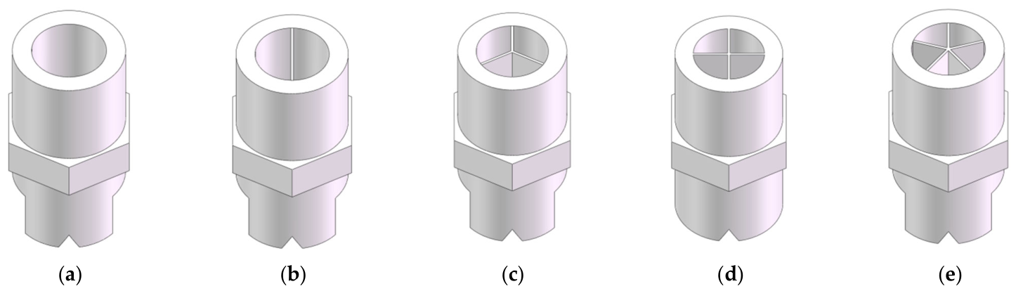
In the single-factor simulations investigating the effect of the number of flow-dividing channels on the flow field and performance of the flat-fan flow-straightening nozzle, the design concept for mitigating the influence of the L-shaped elbow-induced incoming flow on the fan-shaped spray pattern was as follows: the irregular bulk flow was first divided into several small streams, which were then rectified and recombined into a regular, uniform flow, thereby achieving the desired flow stabilization. Five levels of the number of flow-dividing channels, namely {1, 2, 3, 4, 5}, were selected as the test factor. In the experimental design, the vane insertion depth was set to 10 mm by default, and the vane geometry was set to the star-shaped type by default, as shown in Figure 3.
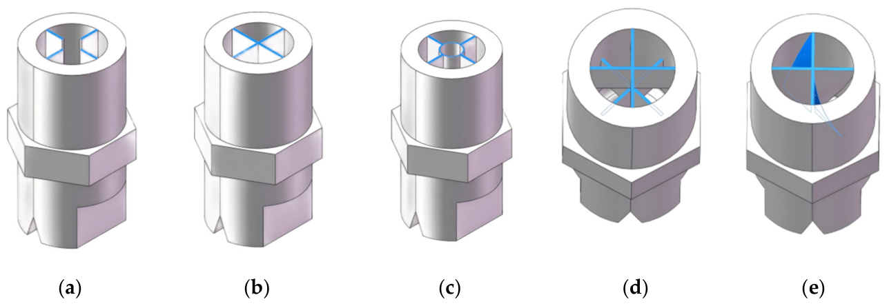
In the single-factor simulations investigating the effect of vane geometry on the flow field and performance of the flat-fan flow-straightening nozzle, five vane geometries were selected as the test factor: star-shaped, multi-plate, projectile-tail-shaped, helical, and segmented. In the experimental design, the vane insertion depth was set to 10 mm by default, and the number of flow-dividing channels was set to four by default, as shown in Figure 4. Different vane geometries have varying capabilities in mitigating inlet flow deflection, transverse momentum, and secondary flows, all of which consequently affect the symmetry, continuity, and uniformity of the outlet fan-shaped velocity field. For the helical vane shown in Figure 4e, the total twist angle was set to 45° over an axial insertion depth of 10 mm, and the mean diameter of the helical guide path was 8.6 mm, the equivalent helical pitch was 80 mm. Based on these parameters, the helix angle was 71.4°, corresponding to 18.6° when defined relative to the nozzle axis. Since the helical vane was evaluated as a comparative vane geometry rather than selected as the final optimized structure, the total twist angle, insertion depth, mean diameter, equivalent pitch, and helix angle were used as its main geometric descriptors.
In the single-factor simulations investigating the effect of vane insertion depth on the flow field and performance of the flat-fan flow-straightening nozzle, five levels of vane insertion depth, namely {8, 9, 10, 11, 12 mm}, were selected as the test factor. In the experimental design, the number of flow-dividing channels was set to four by default, and the vane geometry was set to the star-shaped type by default. The vane insertion depth, defined as the axial length occupied by the vanes within the nozzle interior, alters the length of the flow-straightening zone inside the fan nozzle, thereby affecting the degree to which the irregular and complex flow induced by the L-shaped elbow is divided, rectified, and stabilized within the nozzle.


2.1.3. Box–Behnken Simulation Experimental Design and Evaluation Metrics

To investigate the effects of vane geometry, number of flow-dividing channels, and vane insertion depth on the flow field and performance of the flat-fan flow-straightening nozzle under flow distortion induced by the L-shaped elbow, a Box–Behnken experimental design was conducted based on the nozzle structural configuration and the results of single-factor Fluent simulations. The three test factors were: number of flow-dividing channels (3, 4, 5), vane geometry (projectile-tail-shaped, star-shaped, multi-plate), and vane insertion depth (9 mm, 10 mm, 11 mm). The evaluation metric was the coefficient of variation of normal velocity on the fan-shaped spray plane. Box–Behnken design was employed for the Fluent simulation analysis to determine the optimal combination of structural parameters for the flat-fan flow-straightening nozzle [40,41]. The factor levels are presented in Table 4.
To evaluate the uniformity of the spray pattern of the flat-fan flow-straightening nozzle under different combinations of structural parameters, an evaluation cross-section was established in the Fluent simulation results at a distance of 400 mm downstream of the nozzle outlet. The fan-shaped spray plane was then divided transversely into 15 equally spaced sampling strips. The average normal velocity v ¯ of each sampling strip on the evaluation plane was extracted using Fluent post-processing. The coefficient of variation (CV) was then calculated as the ratio of the standard deviation to the mean value, and the CV value was used to represent the velocity distribution uniformity of the fan-shaped spray plane. A smaller CV value indicates a more uniform liquid distribution on the spray plane and a better flow-straightening effect of the nozzle. It should be noted that the values extracted here represent the average velocity per unit sampling strip rather than mass flux, which was adopted to simplify the calculation and is more convenient in Fluent post-processing. This simplification is justified because, under the same operating conditions and with the same fluid medium, the trend of CV variation for average velocity is generally consistent with that for mass flux. The calculation formulas are given in Equations (1)–(3). v ¯ : mean velocity of the sampling dataset, m/s; S: standard deviation of velocity for the sampling dataset; n: number of sampling points; vi: velocity value at the i-th sampling point, m/s.
v ¯ = 1 n i = 1 n v i
S = 1 n 1 i = 1 n ( v i v ¯ ) 2
C V = S v ¯ × 100 %

2.2. Field Experiment

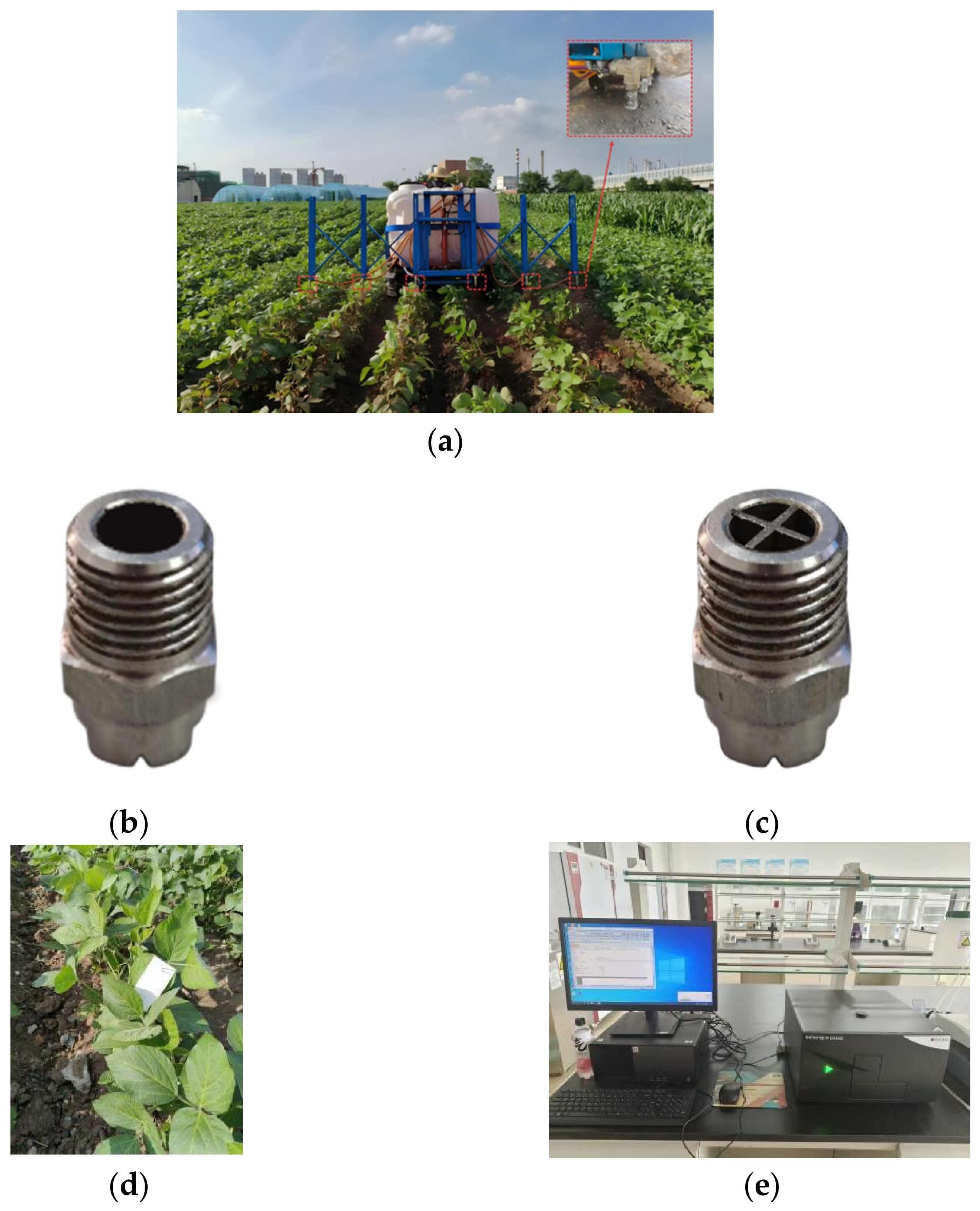
Field experiments were conducted in June 2025 at the experimental farm of Northeast Agricultural University. The sprayer used in the experiment was self-developed by the research group. During the tests, the nozzles were connected to the sprayer boom via L-shaped elbows and fixed beneath the folding boom frame. Soybean seedlings at the early growth stage were selected as the test targets, as shown in Figure 5a. To systematically evaluate the droplet deposition uniformity of the flat-fan flow-straightening nozzle in comparison with the conventional flat-fan nozzle under field conditions, the three nozzles on the left side of the boom were equipped with conventional flat-fan nozzles (Figure 5b), while the three nozzles on the right side were equipped with the developed flow-straightening nozzles (Figure 5c), in order to ensure consistency of experimental factors and minimize errors.
For sampling, water-sensitive papers (4 cm × 9 cm) were placed along the soybean ridge direction according to the actual working width and nozzle spacing [40,42]. Seven sampling zones were arranged along the longitudinal direction with intervals greater than 3 m, and seven soybean seedlings were randomly selected as sampling points within each zone, with the water-sensitive papers fixed onto the seedling leaves. Meteorological conditions, including wind speed and temperature, were recorded before and after the tests. On the afternoon of the test day, the temperature was 24 °C with a southwest wind of force 2–3. The field layout of the water-sensitive papers is shown in Figure 5d.
In the droplet deposition distribution tests, the coefficient of variation of droplet deposition per unit area was adopted as the evaluation index. To eliminate the interference of environmental factors such as air humidity in the field on the water-sensitive papers and to accurately obtain droplet deposition data, an aqueous solution of carmine (Shitou Brand, Shanghai Dye Research Institute Co., Ltd. Shanghai, China) was used as the tracer in the spray mixture [41,43,44]. After the tests, a 50 mL centrifuge tube was used to collect the stock solution from the spray tank for subsequent analysis. The precise quantification of droplet deposition was performed using a multifunctional full-wavelength microplate reader (INFINITE M Nano microplate reader (Tecan, Männedorf, Switzerland)), as shown in Figure 5e. The underlying principle is based on the linear relationship between the characteristic absorbance of the carmine tracer at a specific wavelength and its concentration, which indirectly reflects the droplet volume deposited per unit area of the filter paper [41,43,44]. After the spraying operation, each water-sensitive paper was removed and collected in a No. 7 ziplock bag. Each paper was eluted with 10 mL of deionized water. After elution, 300 μL of the solution was pipetted into a 96-well microplate using a pipette. The microplate was then placed into the multifunctional full-wavelength microplate reader for absorbance measurement, with the maximum absorption wavelength of carmine at 505 nm selected as the detection wavelength.
Based on the absorbance data measured by the multifunctional full-wavelength microplate reader, the droplet deposition per unit area Vi/j at each sampling point was calculated according to Equation (4). Vi/j: droplet deposition per unit area, where i denotes the row number and j denotes the column number, μL/cm2; Vw: volume of carmine eluate, mL; Fs: absorbance of the carmine eluate; Fα: absorbance of the stock solution; N: dilution factor of the stock solution; S: area of the sampling filter paper, cm2.
V i / j = V W × F s N × F α × S × 10 3

3. Results and Discussion

3.1. Flow Field Analysis in the L-Shaped Elbow

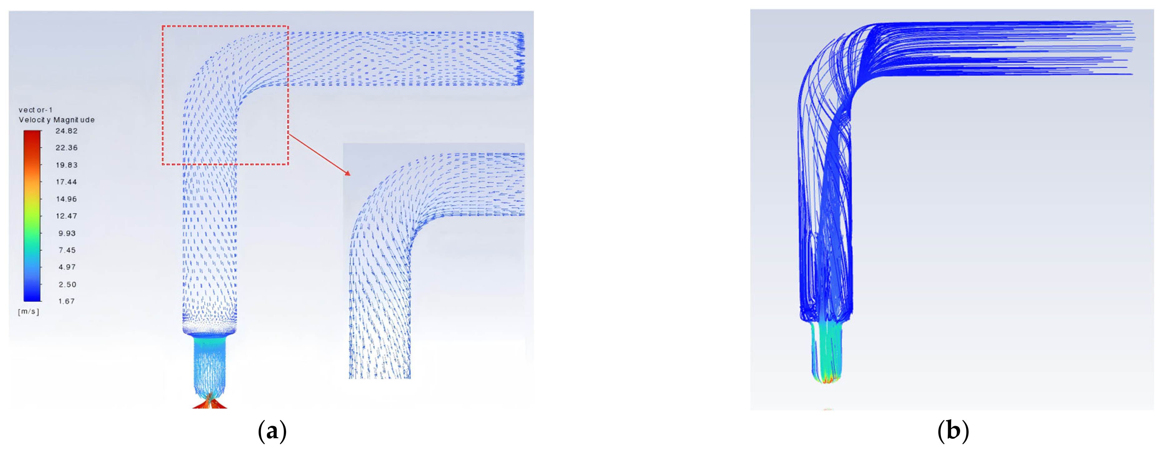
When the nozzle is mounted on an L-shaped elbow, the flow direction of the liquid changes abruptly after passing through the elbow, generating internal secondary flows. The L-shaped elbow not only serves as a geometric element that redirects the flow but also plays a significant role in inducing pre-swirl, enhancing flow disturbances, and altering energy distribution. As shown in Figure 6, the velocity vector and fluid trace diagrams of the flow inside the L-shaped elbow are presented. As the liquid flows through the L-shaped bend, the mainstream direction undergoes a sudden deflection, and fluid particles migrate toward the outer wall due to the centrifugal effect induced by curvature. During flow through the elbow, the liquid is subjected to centrifugal forces, resulting in higher pressure and relatively lower velocity at the outer side (away from the center of curvature), and lower pressure with higher velocity at the inner side (near the center of curvature). For the internal flow passage of the nozzle connected to the L-shaped elbow, the liquid entering the orifice is not in an ideal uniform and steady state, but is rather subjected to the coupled effects of elbow-induced secondary flows, localized pressure drops, flow separation, and enhanced turbulence, which collectively influence the spray pattern uniformity of the flat-fan nozzle.

3.2. Fluent Single-Factor Simulation Analysis

3.2.1. Effect of the Number of Flow-Dividing Channels on the Flow Field

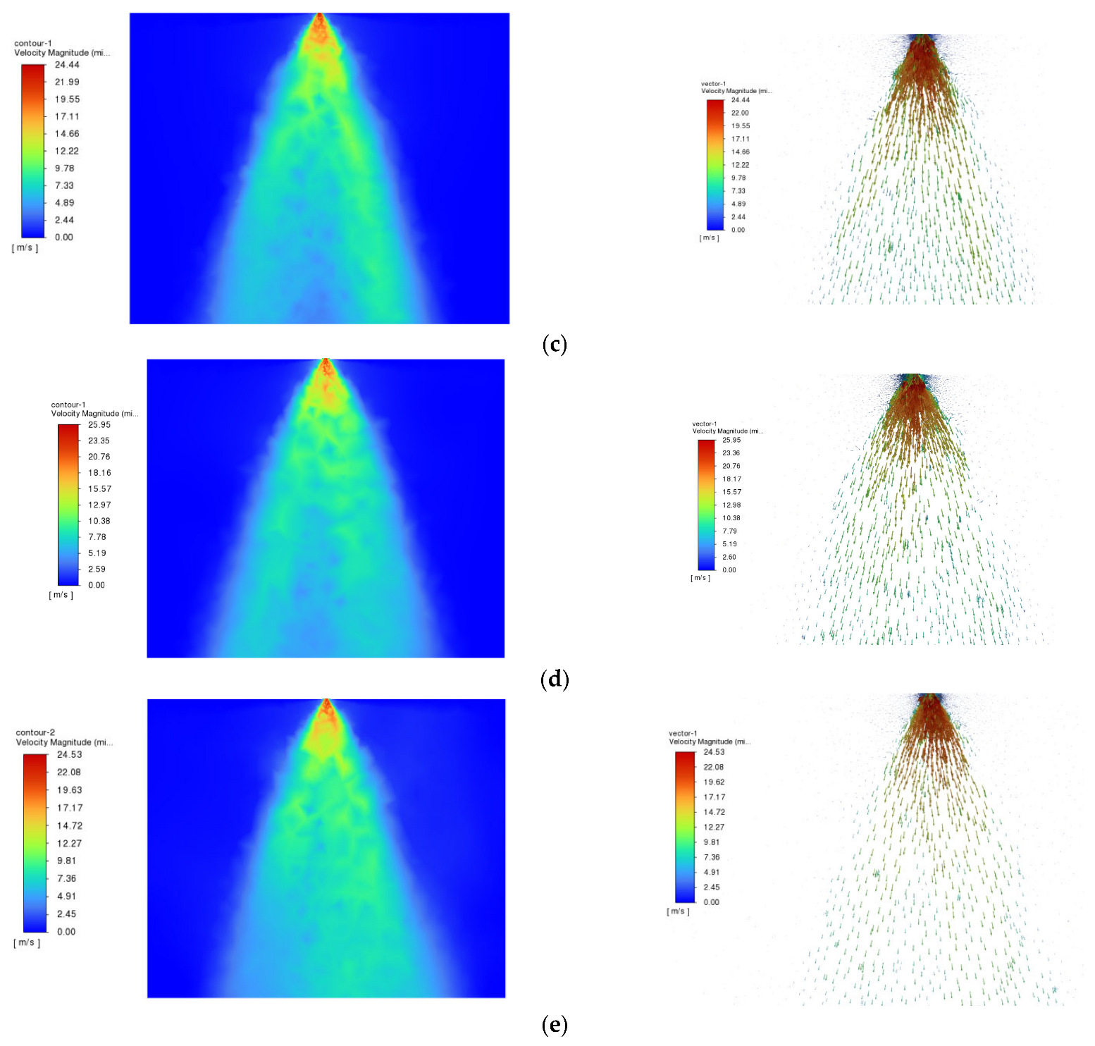
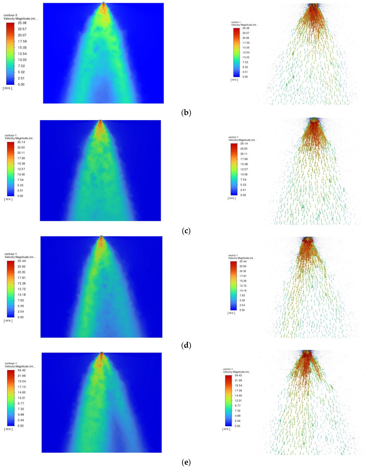
Figure 7 presents the simulated flow field contours on the fan-shaped spray plane for different numbers of flow-dividing channels. The contours clearly show that as the number of flow-dividing channels increases, the velocity distribution of the spray pattern at the nozzle outlet transitions progressively from “deflected, discrete, and non-uniform” toward “symmetric, continuous, and uniform.” However, a larger number of channels is not always beneficial; the overall trend exhibits an initial improvement, followed by saturation and even localized degradation.
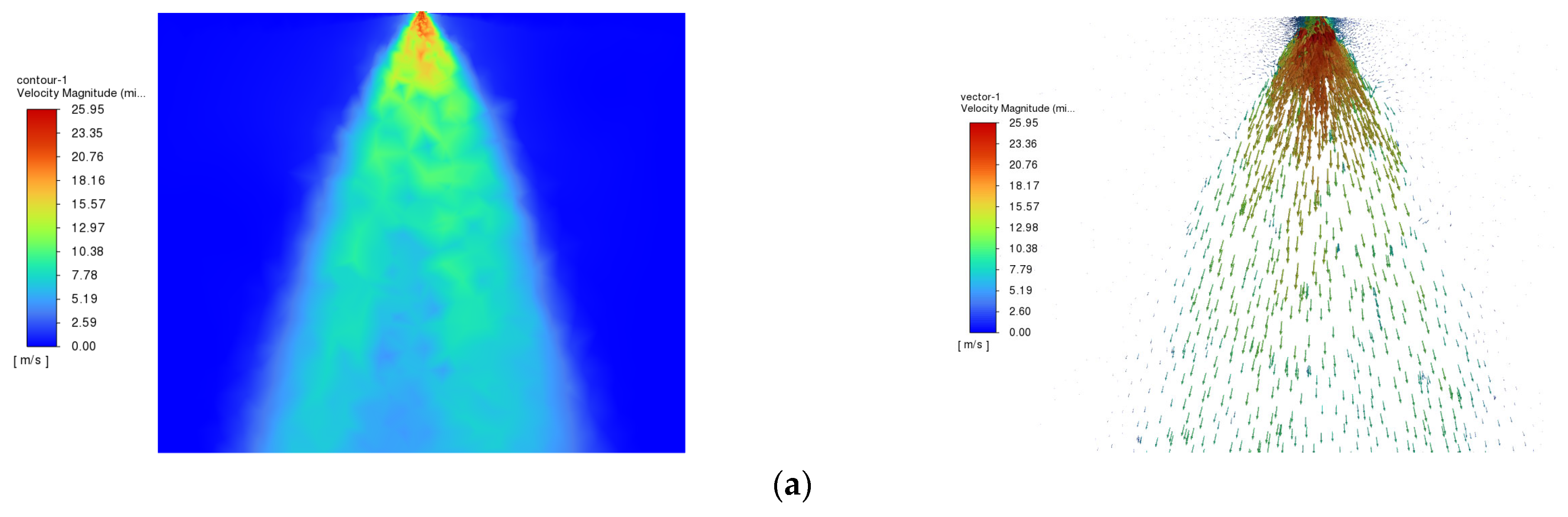
As shown in Figure 7a, under the complex flow conditions induced by the L-shaped elbow, the conventional flat-fan nozzle exhibits a pronounced central low-velocity zone and a tendency toward flow splitting, with relatively prominent high-velocity regions on both sides. This indicates the influence of flow deflection and irregular flow caused by the L-shaped elbow on the spray performance of the conventional nozzle. Such a flow field typically corresponds to unstable left–right flow rate distribution, inconsistent liquid film breakup conditions across different regions, and a tendency for excessive spray on one side and insufficient spray on the other, resulting in significant transverse variation in swath uniformity. Compared with Figure 7a, Figure 7b shows a marked improvement. The central region of the spray fan became more continuous, the previously pronounced flow splitting is diminished, and the overall spray contour becomes more complete.
Figure 7c,d exhibit good symmetry and uniformity, with a relatively full and well-developed spray pattern. Compared with Figure 7a,b, the boundaries on both sides of the spray plane are smoother, the velocity transition in the central region is more gradual, and the overall fan-shaped pattern is more stable and uniform. At this stage, the flow-straightening structure begins to take effect, clearly demonstrating the functions of flow diversion and rectification, effectively mitigating the complex effects of the L-shaped elbow and resulting in a more uniform fan-shaped spray pattern. However, compared with Figure 7c (three channels), Figure 7d shows a more concentrated high-velocity core near the nozzle outlet at the top of the fan-shaped spray plane, with a locally higher peak velocity. This indicates that although the four-channel configuration further enhances flow rectification, it also leads to a relatively concentrated high-velocity region near the outlet, as the maximum velocity in the contour is higher than that in Figure 7c. Figure 7e shows that with a further increase in the number of channels, the spray pattern remains essentially symmetric; however, compared with Figure 7c,d, no further substantial improvement was observed, indicating that the flow-straightening effect tends to reach saturation.

3.2.2. Effect of Vane Geometry on the Flow Field

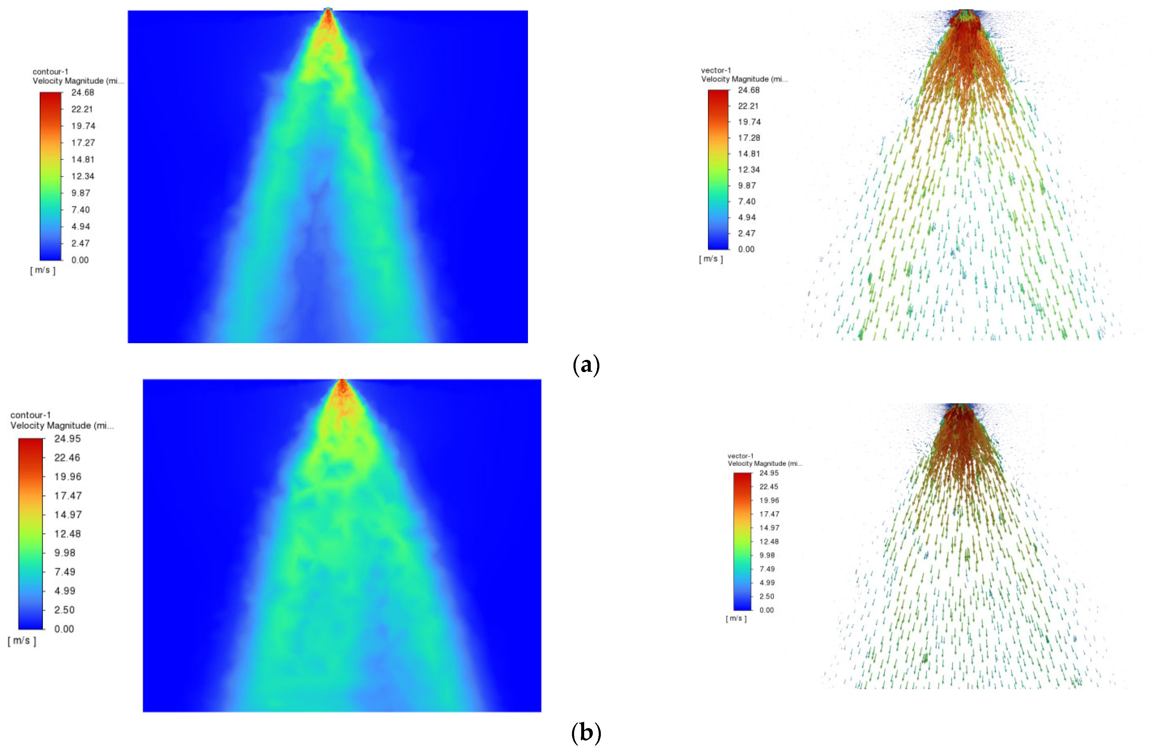
Figure 8 presents the simulated flow field contours on the fan-shaped spray plane for different vane geometries. The contours indicate that different vane geometries exhibit varying capabilities in mitigating inlet flow deflection and irregular flow induced by the L-shaped elbow, resulting in notable differences in the symmetry, continuity, uniformity, and maximum outlet velocity of the fan-shaped velocity field. An appropriate vane geometry can significantly improve the uniformity of the outlet velocity field of the flat-fan nozzle under L-shaped elbow incoming flow conditions.
Figure 8a,c exhibit good symmetry and uniformity, with relatively full spray patterns and complete contour shapes. The velocity transition in the central region is more gradual, and the overall fan-shaped pattern is more stable and uniformly symmetric. This indicates that, among the geometries tested, the star-shaped and projectile-tail-shaped vanes effectively achieve flow diversion, rectification, and redistribution of the distorted flow induced by the L-shaped elbow. After the fluid is rapidly divided into multiple relatively balanced substreams, the flow deflection and secondary flow intensity caused by the elbow are significantly weakened, allowing the outlet velocity field to recover to a well-symmetric state. However, the contours also show that the spray angle of the projectile-tail-shaped vane configuration is notably smaller than that of the star-shaped configuration. This may be attributed to the presence of a central circular dividing passage within the projectile-tail-shaped vane, which causes the fluid to form a concentrated central core flow during the diversion stage. Consequently, the central lower region of the velocity contour for the projectile-tail-shaped configuration appears more fully developed and transitions more naturally than that of the star-shaped configuration, but this comes at the cost of a reduced spray angle.
Figure 8b shows the velocity contour for the multi-plate vane configuration. Although the multi-plate structure also possesses flow-diversion and rectification capabilities, a clear drawback is evident in the reduced velocity continuity in the lower central region. From the contour, the multi-plate structure achieves a certain degree of flow diversion and stabilization in the upper region; however, as the spray pattern expands downward, the velocity continuity near the central axis is insufficient, and the lower central zone exhibits a pronounced weakening. This indicates that, although the multi-plate configuration constrains and stabilizes the flow direction, the substreams do not reunite into an ideal stabilized flow pattern near the outlet. In contrast, the projectile-tail-shaped vane, with its central circular dividing passage, creates a concentrated central core flow during the diversion stage, an effect that the multi-plate configuration lacks, leading to the observed inferior lower central flow field.
Figure 8d,e show notably poorer flow-straightening performance compared with the other three vane geometries. The helical vane (Figure 8d) does not simply “eliminate” swirling flow, but rather alters the flow path through helical curved guidance. As a result, the contour exhibits a significantly imbalanced left–right velocity distribution and over-rectification of the flow direction in localized regions. The helical vane fails to effectively divert, rectify, and stabilize the distorted flow induced by the L-shaped elbow, and instead may introduce new tangential disturbances within the nozzle. The segmented vane configuration (Figure 8e), despite attempting to achieve flow field correction through multi-stage diversion and rectification, ultimately results in poor left–right consistency of the fan-shaped spray pattern. This is likely due to localized disturbances at the segment joints, leading to uneven redistribution and rectification of the substreams after diversion, which compromises the overall spraying performance.

3.2.3. Effect of Vane Insertion Depth on the Flow Field

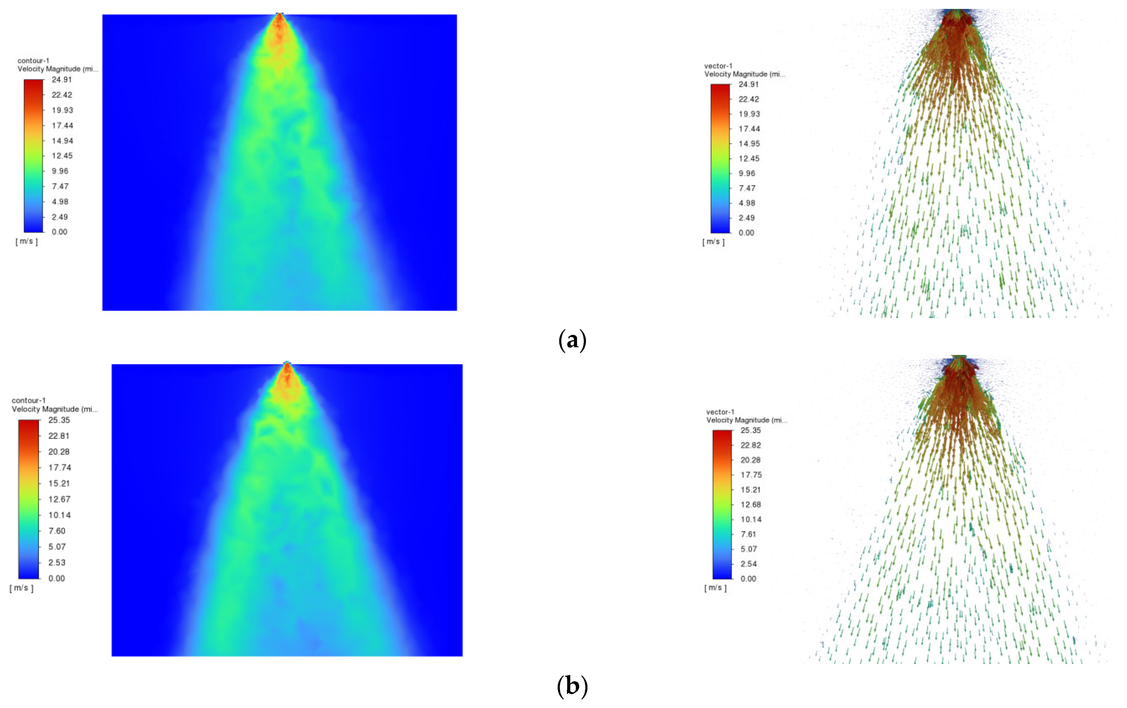
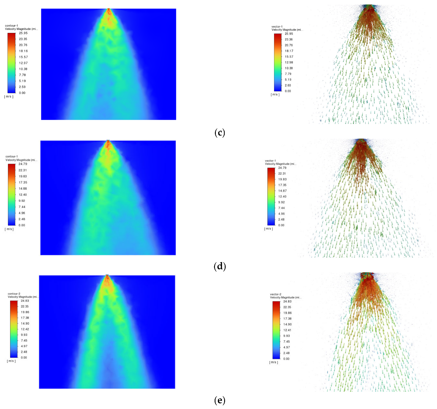
Figure 9 presents the simulated flow field contours on the fan-shaped spray plane for different vane insertion depths. From a structural perspective, the vane insertion depth determines the axial length of the flow-straightening zone within the flat-fan nozzle, thereby affecting the degree to which the irregular and complex flow induced by the L-shaped elbow is divided, rectified, and stabilized inside the nozzle. The simulation contours indicate that as the insertion depth increases from 8 mm to 12 mm, the uniformity and stability of the fan-shaped outlet flow field exhibit a trend of “initial improvement followed by deterioration.” Concurrently, the maximum initial droplet velocity on the fan-shaped spray plane follows a trend of “initially increasing and then decreasing” with increasing insertion depth, suggesting that the flow-straightening vanes can reduce energy loss caused by the elbow to a certain extent. However, the peak initial velocity occurs at an insertion depth of 10 mm, after which it begins to decline, indicating the existence of an optimal insertion depth.
At an insertion depth of 8 mm (Figure 9a), the overall uniformity of the fan-shaped spray pattern is relatively satisfactory; however, the spray angle is notably smaller than that of the other groups. As the insertion depth increases to 9 mm and 10 mm (Figure 9b,c), the fluid undergoes more adequate flow guidance and rectification within the vane passage. At these depths, the flow deflection and localized non-uniform velocity distribution induced by the elbow are further mitigated, and the integrity, symmetry, and continuity of the outlet fan-shaped flow field are significantly improved compared with the 8 mm case. The flow-straightening zone is now sufficiently long to accomplish effective rectification, and the outlet velocity contours appear more complete and continuous.
As the insertion depth continues to increase to 11 mm (Figure 9d), the flow-straightening nozzle still maintains a relatively good rectification effect; however, the maximum initial droplet velocity begins to decrease, indicating that beyond 10 mm, further lengthening of the flow-straightening zone does not continue to improve the outlet flow field quality, but instead leads to a slight decline. At an insertion depth of 12 mm (Figure 9e), this trend becomes more pronounced, as the velocity contour begins to exhibit poorer uniformity in the middle and lower regions. This suggests that an excessively long flow-straightening zone may cause the fluid to remain constrained within the vane passages for too long, potentially due to increased additional resistance and enhanced localized disturbances, which are detrimental to achieving an ideal outlet velocity distribution.

3.3. Box–Behnken Simulation Experimental Results and Analysis

The factor levels presented in Table 5 were input into Design-Expert 13.0.5 for experimental design, resulting in a total of 17 experimental runs. For each run, the data from the sampling strips were replicated three times, and the results were averaged. The simulation experimental design and corresponding results are presented in Table 5. Analysis of variance (ANOVA) was subsequently performed using the Design-Expert software.
From the ANOVA results presented in Table 6, the order of significance of the factors affecting the coefficient of variation of normal velocity was ranked as follows: x32, x22, x12, x3, x2, x1x3, x2x3, x1, x1x2. The interaction term between the number of flow-dividing channels and vane insertion depth (x1x2) was found to have no significant effect on the coefficient of variation of normal velocity (p > 0.05), whereas all other factors and interaction terms showed highly significant or significant effects (p < 0.05).
After incorporating the non-significant terms into the residual term, the regression equation relating the coefficient of variation of normal velocity to the various factors was obtained, as shown in Equation (5).
Y 1 = 16.12 + 0.37 x 1 + 0.54 x 2 + 0.98 x 3 0.72 x 1 x 3 0.60 x 2 x 3 + 0.74 x 1 2 + 1.12 x 2 2 + 1.94 x 3 2
A lack-of-fit test was performed on the regression equation relating the coefficient of variation of normal velocity to the experimental factors. After eliminating the non-significant terms, the ANOVA for the coefficient of variation of normal velocity was re-evaluated, and the results are presented in Table 7. The lack-of-fit p-value was 0.0768, which is not significant, indicating that the regression equation is accurate and that no other major factors affecting the evaluation metric were omitted. A significant quadratic relationship exists between the experimental factors and the evaluation metric, and the regression model demonstrates a good fit, satisfying the requirements for design prediction.
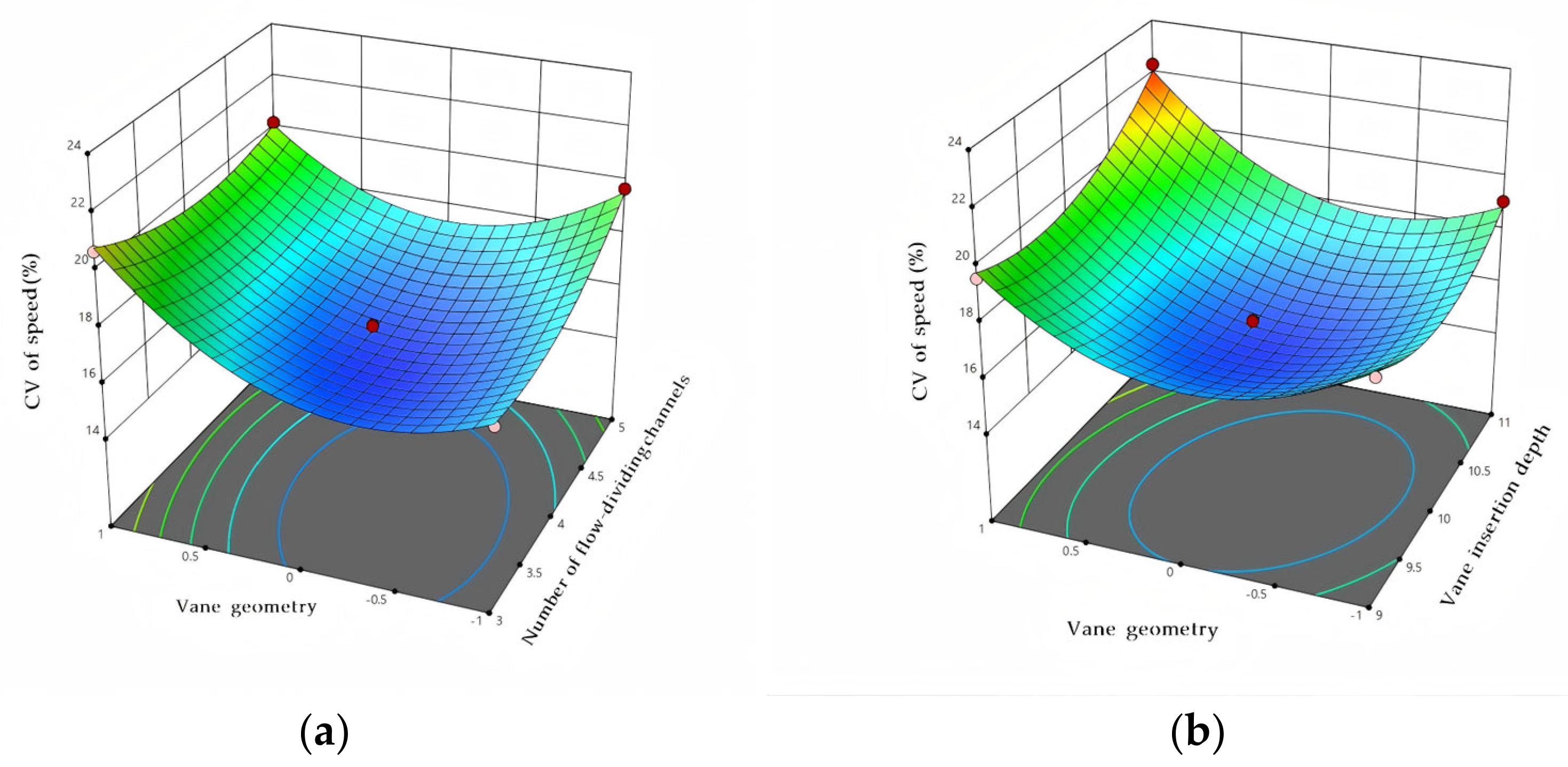
From Table 7, it can be observed that the interactions between the number of flow-dividing channels and vane geometry, as well as between vane insertion depth and vane geometry, have significant effects on the coefficient of variation of normal velocity of the spray pattern for the flat-fan flow-straightening nozzle. Therefore, response surface analysis was conducted. As shown in Figure 10a, the response surface exhibits a pronounced curvature, with the slope changing more substantially along the direction of vane geometry than along the direction of the number of flow-dividing channels, indicating that, within the tested factor level ranges, vane geometry has a more significant influence on the flow-straightening effect than the number of channels. Specifically, when the vane geometry is of a certain type, an appropriate increase in the number of channels contributes to improved flow-straightening performance; however, under other vane geometries, increasing the number of channels may instead lead to a deterioration in performance.
The interaction between vane insertion depth and vane geometry is shown in Figure 10b. It can be observed that the response surface exhibits a pronounced slope variation along the direction of vane insertion depth, and the surface morphology differs markedly under different vane geometries, indicating that vane insertion depth has a significant effect on flow-straightening performance, and that this effect is modulated by vane geometry. In particular, for certain vane geometries, increasing the insertion depth can significantly improve flow-straightening performance; whereas for other geometries, the effect of insertion depth variation is relatively moderate. This suggests a strong interaction between vane geometry and vane insertion depth, and that the two parameters should be optimized together to fully realize the optimal operational performance of the flat-fan flow-straightening nozzle.
By combining the effects of each experimental factor on the response surfaces of the evaluation metric, the regression equation relating the experimental factors to the response was further analyzed. With the minimization of the coefficient of variation of normal velocity as the optimization objective, several sets of solutions were obtained, from which the optimal configuration was selected: four flow-dividing channels, a vane insertion depth of 10 mm, and a star-shaped vane geometry.
To verify the reliability of the optimized parameters, the simulation was repeated under the optimal combination following the same procedure, with the sampling strip data replicated three times for each experimental run. The resulting coefficients of variation of normal velocity were 16.22%, 15.97%, and 16.16%, yielding an average value of 16.12%. The repeated experimental results were in good agreement with the predicted theoretical value, thus validating the accuracy of the optimization.

3.4. Field Comparative Test Results and Analysis of the Flat-Fan Flow-Straightening Nozzle

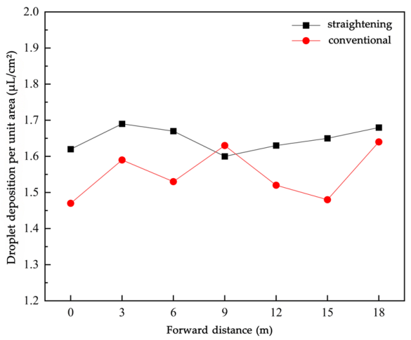
The droplet deposition per unit area at each sampling point was calculated according to Equation (4), and the droplet deposition results are presented in Table 8. The average deposition at each sampling point was calculated for analysis. The droplet deposition amounts of the two different types of flat-fan nozzles at various sampling positions are shown in Figure 11.
To more objectively compare and analyze the differences between the conventional flat-fan nozzle and the flat-fan flow-straightening nozzle, an analysis of variance (ANOVA) was performed on the droplet deposition per unit area. The ANOVA results indicated that the flat-fan flow-straightening nozzle and the conventional flat-fan nozzle exhibited a statistically significant difference in droplet deposition, with a highly significant difference between the two nozzle types (p < 0.01). Specifically, a one-way ANOVA was conducted using SPSS software (version 26.0) to compare the means of droplet deposition per unit area between the two nozzle types, and the results are presented in Table 9.
The coefficient of variation (CV) was adopted as the metric for evaluating the uniformity of spray deposition distribution. A smaller CV value indicates a more uniform deposition distribution. The standard deviation of droplet deposition was calculated for each sampling point, and the coefficient of variation of spray deposition distribution was calculated according to Equations (6) and (7). S: standard deviation of droplet deposition; x ¯ : mean droplet deposition per unit area, μL/cm2.
S = i = 1 n ( x i x ¯ ) 2 n 1
C V = S X ¯ × 100 %
The coefficient of variation of spray deposition distribution for the conventional flat-fan nozzle was calculated to be CV = 4.46%, while that for the flat-fan flow-straightening nozzle was CV = 2.03%.
To address the problem in field plant protection operations where flat-fan nozzles, when subjected to the complex flow conditions induced by L-shaped elbows, experience abrupt changes in flow direction and internal secondary flows that consequently affect droplet deposition uniformity, the flat-fan flow-straightening nozzle developed in this study demonstrated, under identical experimental conditions, a coefficient of variation of droplet deposition (CV) of 2.03%, which represents a 54.5% reduction compared with that of the conventional flat-fan nozzle (4.46%). This result indicates a significant improvement in droplet deposition uniformity and the coefficient of variation of droplet deposition amount is lower than the 20% limit specified in the Chinese national standard GB/T 24677.1—2009 [45]. The nozzle designed in this study can effectively maintain droplet deposition stability under complex dynamic operating conditions.

3.5. Limitations and Future Research

This study was evaluated only under soybean seedlings, a single spray pressure, and a specific boom configuration; therefore, the obtained optimal structure should be understood as the result under the current test conditions rather than a universal optimum. Future work can conduct systematic experiments under different crop canopies, nozzle installation heights, travel speeds, wind speeds, and spray pressures to clarify the applicability and parameter robustness of the proposed flow-straightening nozzle under a wider range of practical operating conditions.
In this study, the coefficient of variation of normal velocity at 400 mm downstream was used as a surrogate index for spray pattern uniformity. This metric is suitable for comparing internal flow uniformity among different nozzle structures, but it cannot fully replace direct atomization indicators such as droplet size distribution, VMD, spray angle, liquid-sheet breakup, and deposition/drift characteristics. Future work can combine high-speed imaging, droplet-size measurement, or deposition distribution experiments to further verify the relationship between normal-velocity uniformity and actual spraying performance, thereby improving the completeness and persuasiveness of the evaluation framework.

4. Conclusions

To address the non-uniform velocity distribution on the spray fan plane and the reduced droplet deposition stability of flat-fan nozzles caused by inlet flow distortion under L-shaped elbow connection conditions, this study designed a flat-fan nozzle with built-in flow-straightening vanes and evaluated its performance through CFD simulation, Box–Behnken response surface optimization, and field deposition experiments. The main conclusions are as follows:
  • The L-shaped elbow induces abrupt changes in flow direction, local flow deflection, and enhanced secondary flows at the nozzle inlet, resulting in non-uniform velocity distribution, localized high-velocity regions, and reduced spray fan continuity at the outlet of the conventional flat-fan nozzle. The built-in flow-straightening vanes diverted and guided the elbow-induced distorted flow, improving the symmetry and uniformity of the velocity field on the spray plane.
  • The structural parameters of the flow-straightening vanes significantly affected the coefficient of variation of normal velocity on the spray plane. The Box–Behnken response surface analysis showed that the order of influence was vane geometry, vane insertion depth, and number of flow-dividing channels. Significant interaction effects were observed between vane geometry and the number of channels, and between vane geometry and insertion depth. The optimal structural parameters were four flow-dividing channels, star-shaped vanes, and an insertion depth of 10 mm. Under this combination, the coefficient of variation of normal velocity at the evaluation cross-section 400 mm downstream of the nozzle was 16.12%.
  • The field comparative tests demonstrated that the designed flow-straightening flat-fan nozzle improved foliar droplet deposition uniformity on soybean seedlings at the early growth stage. Under identical operating conditions, the coefficient of variation of droplet deposition was 4.46% for the conventional flat-fan nozzle and 2.03% for the flow-straightening nozzle, representing a 54.5% reduction. The difference in deposition between the two nozzle types was statistically significant. These results indicate that the built-in flow-straightening structure improved spray stability and deposition uniformity under complex pipeline connection conditions.

Author Contributions

Writing—original draft, S.Z. and G.Z.; writing—review and editing, S.Z., G.Z. and B.L.; investigation, S.Z. and C.J.; formal analysis, S.Z. and F.L.; visualization, B.L., G.Z. and Y.Y.; resources, Y.Y. and F.L.; methodology, S.Z., B.L. and C.J.; validation, B.L. and C.J.; project administration, S.Z. and F.L.; data curation, S.Z. and G.Z.; conceptualization, G.Z., S.Z. and B.L.; supervision, Y.Y. All authors have read and agreed to the published version of the manuscript.

Funding

This research was funded by the Heilongjiang Spring Goose Program for Innovative Talents (Grant No. CYCX24005) and the Science and Technology Innovation Project for Black Soil Protection and Utilization (Grant No. XDA28030302).

Institutional Review Board Statement

Not applicable.

Data Availability Statement

The raw data supporting the conclusions of this article will be made available by the authors on request.

Conflicts of Interest

Author Guopeng Zhao was employed by the company Shaanxi Aircraft Industry Co., Ltd.. The remaining authors declare that the research was conducted in the absence of any commercial or financial relationships that could be construed as a potential conflict of interest.

References

  1. Chen, S.; Lan, Y.; Zhou, Z.; Ouyang, F.; Wang, G.; Huang, X.; Deng, X.; Cheng, S. Effect of droplet size parameters on droplet deposition and drift of aerial spraying by using plant protection UAV. Agronomy 2020, 10, 195. [Google Scholar] [CrossRef] [Scilit]
  2. Pan, X.; Yang, S.; Gao, Y.; Wang, Z.; Zhai, C.; Qiu, W. Evaluation of spray drift from an electric boom sprayer: Impact of boom height and nozzle type. Agronomy 2025, 15, 160. [Google Scholar] [CrossRef] [Scilit]
  3. Li, S.; Chen, C.; Wang, Y.; Kang, F.; Li, W. Study on the atomization characteristics of flat fan nozzles for pesticide application at low pressures. Agriculture 2021, 11, 309. [Google Scholar] [CrossRef] [Scilit]
  4. Nogueira Martins, R.; Moraes, H.M.F.; Freitas, M.A.M.; Lima, A.C.; Furtado Junior, M.R. Effect of nozzle type and pressure on spray droplet characteristics. Idesia 2021, 39, 101–107. [Google Scholar] [CrossRef] [Scilit]
  5. Hu, S.; Xu, X.; Liu, J.; Guo, J.; Guan, R.; Zhou, Z.; Lan, Y.; Chen, S. Movement characteristics of droplet deposition in flat spray nozzle for agricultural UAVs. Agriculture 2024, 14, 1994. [Google Scholar] [CrossRef] [Scilit]
  6. Kluza, P.A.; Kuna-Broniowska, I.; Parafiniuk, S. Modeling and prediction of the uniformity of spray liquid coverage from flat fan spray nozzles. Sustainability 2019, 11, 6716. [Google Scholar] [CrossRef] [Scilit]
  7. Chen, H.; Duan, R.; Wang, Q.; Gong, W. Research on the spray characteristics of the fan nozzle based on coupled analysis of the internal and external flow fields. Phys. Fluids 2025, 37, 065163. [Google Scholar] [CrossRef] [Scilit]
  8. Aliverdi, A.; Borghei, M. Spray coverage and biological efficacy of single, twin symmetrical, and twin asymmetrical flat fan nozzles. Acta Technol. Agric. 2021, 24, 92–96. [Google Scholar] [CrossRef] [Scilit]
  9. Abuhatira, A.A.; Salim, S.M.; Vorstius, J.B. Numerical simulation of turbulent pipe flow with 90-degree elbow using wall y+ approach. In Proceedings of the ASME 2021 International Mechanical Engineering Congress and Exposition, Virtual, 1–5 November 2021; ASME: New York, NY, USA, 2021. [Google Scholar] [CrossRef] [Scilit]
  10. Rohrig, R.; Jakirlic, S.; Tropea, C. Comparative computational study of turbulent flow in a 90 degrees pipe elbow. Int. J. Heat Fluid Flow 2015, 55, 120–131. [Google Scholar] [CrossRef] [Scilit]
  11. Venters, R.; Helenbrook, B.; Ahmadi, G. Numerical simulations of turbulent flow through a 90 degrees elbow. In Proceedings of the ASME-JSME-KSME 2019 8th Joint Fluids Engineering Conference, San Francisco, CA, USA, 28 July–1 August 2019; ASME: New York, NY, USA, 2019. [Google Scholar] [CrossRef] [Scilit]
  12. Wang, S.; Ren, C.; Sun, Y.; Yang, X.; Tu, J. A study on the instantaneous turbulent flow field in a 90-degree elbow pipe with circular section. Sci. Technol. Nucl. Install. 2016, 2016, 5265748. [Google Scholar] [CrossRef] [Scilit]
  13. Kabacinski, M.; Pospolita, J. Effect of distortion in velocity profile on flow measurements using averaging flow sensors. Sensors 2020, 20, 2839. [Google Scholar] [CrossRef] [Scilit]
  14. Koo, D.; Goncalves, C.G.; Askew, S.D. Agricultural spray drone deposition, Part 2: Operational height and nozzle influence pattern uniformity, drift, and weed control. Weed Sci. 2024, 72, 824–832. [Google Scholar] [CrossRef] [Scilit]
  15. Appah, S.; Ayambire, C.A.; Asante, E.A. Charged pesticide spray swath and volumetric droplets distribution impact by nozzle types, spacing and height. J. Sci. Technol. 2025, 43, 56–72. [Google Scholar] [CrossRef] [Scilit]
  16. Guo, Y.; Wang, H.; Sun, W.; Sun, Y.; Xing, R.; Zhang, K.; Fang, X.; Sui, B.; Xu, J. The effect of airflow-assisted parameters on droplet deposition on soybean leaves at the V7 growth stage. Agronomy 2025, 15, 141. [Google Scholar] [CrossRef] [Scilit]
  17. Thornton, K.L.; Deveau, J.; Trueman, C.L. Deposition aids, nozzle selection and carrier volume on canopy deposition and management of Cercospora leaf spot in sugarbeet (Beta vulgaris L.). Crop Prot. 2023, 167, 106198. [Google Scholar] [CrossRef] [Scilit]
  18. Alheidary, M.; Douzals, J.P.; Sinfort, C. How nozzle type, boom height and wind speed affect the sedimentation spray drift as measured in a wind tunnel. Acta Hortic. 2021, 1315, 513–520. [Google Scholar] [CrossRef] [Scilit]
  19. McGinty, J.A.; Morgan, G.D.; Dotray, P.A.; Baumann, P.A. Herbicide formulation, spray nozzle design, and operating pressure affects the droplet size spectra of agricultural sprays. J. Exp. Agric. Int. 2019, 38, 1–7. [Google Scholar] [CrossRef] [Scilit]
  20. Mughal, W.; Pei, J.; Liu, J.; Wang, W.; Hussain, J.; Samo, I.A.; Rongjun, X.; Zhang, Y. Experimental investigation of flat fan nozzle V-cut depths and its impact on spray characteristics. Sci. Rep. 2025, 15, 22959. [Google Scholar] [CrossRef] [Scilit]
  21. Ma, X.; Wang, S.; Li, F.; Zhang, H.; Jiang, S.; Sui, M. Effect of air flow rate and temperature on the atomization characteristics of biodiesel in internal and external flow fields of the pressure swirl nozzle. Energy 2022, 253, 124112. [Google Scholar] [CrossRef] [Scilit]
  22. Vashahi, F.; Lee, J.K. Insight into the dynamics of internal and external flow fields of the pressure swirl nozzle. At. Sprays 2018, 28, 1001–1028. [Google Scholar] [CrossRef] [Scilit]
  23. Aliverdi, A.; Aliverdi, A. Increased outlet design of flat-fan nozzle improves octocopter unmanned aerial vehicle sprayer’s efficiency. Crop Prot. 2024, 182, 106736. [Google Scholar] [CrossRef] [Scilit]
  24. Butts, T.R.; Fritz, B.K.; Davis, J.A.; Spurlock, T.N. Spray coverage and deposits from a remotely piloted aerial application system using various nozzle types. Front. Agron. 2024, 6, 1493799. [Google Scholar] [CrossRef] [Scilit]
  25. Zhang, R.; Hu, P.; Li, L.; Tang, Q.; Yang, J.; Yang, J.; Chen, L. Fine-grained method for determining size and velocity distribution patterns of flat-fan nozzle-atomised droplets based on phase Doppler interferometer. Comput. Electron. Agric. 2024, 225, 109343. [Google Scholar] [CrossRef] [Scilit]
  26. Yan, W.; Li, L.; Song, J.; Hu, P.; Xu, G.; Wu, Q.; Zhang, R.; Chen, L. Deep learning-assisted measurement of liquid sheet structure in the atomization of hydraulic nozzle spraying. Agronomy 2025, 15, 409. [Google Scholar] [CrossRef] [Scilit]
  27. Asako, Y.; Hong, C.; Yamaguchi, Y.; Faghri, M.; Tan, L.K.; Che Sidik, N.A. Physically realistic inlet-velocity profiles in duct flows. Heat Transf. Eng. 2025, 46, 240–251. [Google Scholar] [CrossRef] [Scilit]
  28. Smyk, E.; Stopel, M.; Rachwalski, A. Impact of honeycomb straightener parameters on operation in a straight duct. J. Theor. Appl. Mech. 2025, 63, 781–794. [Google Scholar] [CrossRef] [Scilit]
  29. Dushin, N.; Mikheev, N.; Valeev, A.; Zaripov, D.; Dushina, O.; Kratirov, D. Enhanced acoustic and hydrodynamic performance of cylindrical flow conditioners using rubber and steel fillers for gas metering. Flow Meas. Instrum. 2025, 102, 102768. [Google Scholar] [CrossRef] [Scilit]
  30. Puspitasari, D.; Wirandha, E.; Syahputra, B.; Ellyanie; Marwani; Endrawijaya, I. Effect of vertical the flow straightener position to velocity gas flow profile in sampling point of stack. AIP Conf. Proc. 2023, 2689, 070024. [Google Scholar] [CrossRef] [Scilit]
  31. Hirt, C.W.; Nichols, B.D. Volume of fluid (VOF) method for the dynamics of free boundaries. J. Comput. Phys. 1981, 39, 201–225. [Google Scholar] [CrossRef] [Scilit]
  32. Vashahi, F.; Ra, S.; Choi, Y.; Lee, J. An experimental and CFD analysis of a two-phase flow air induction nozzle with agricultural application. In Proceedings of the 6th International Conference on Simulation and Modeling Methodologies, Technologies and Applications, Lisbon, Portugal, 29–31 July 2016; IEEE: Piscataway, NJ, USA, 2016; pp. 172–178. [Google Scholar] [CrossRef] [Scilit]
  33. Wang, L.; Chen, L.; Fang, B. Numerical simulation of internal flow and external atomization in pressure swirl nozzle. J. Phys. Conf. Ser. 2019, 1300, 012082. [Google Scholar] [CrossRef] [Scilit]
  34. Chen, Y.; Luo, J.; Wu, F.; Zhang, Z.; Zhao, Z.; Zhang, L.; Luo, C.; Li, X. Multi-objective optimization on flow characteristics of pressure swirl nozzle: A LES-VOF simulation. Int. Commun. Heat Mass Transf. 2022, 133, 105926. [Google Scholar] [CrossRef] [Scilit]
  35. Yan, J.; Wang, J.; Lv, C.; Wang, S. A CFD simulation method for nozzle droplet deposition characteristics and corresponding experimental validation. J. Agric. Eng. 2025, 56, 1708. [Google Scholar] [CrossRef] [Scilit]
  36. Box, G.E.P.; Behnken, D.W. Some new three level designs for the study of quantitative variables. Technometrics 1960, 2, 455–475. [Google Scholar] [CrossRef]
  37. Ferreira, S.L.C.; Bruns, R.E.; Ferreira, H.S.; Matos, G.D.; David, J.M.; Brandao, G.C.; da Silva, E.G.P.; Portugal, L.A.; dos Reis, P.S.; Souza, A.S.; et al. Box-Behnken design: An alternative for the optimization of analytical methods. Anal. Chim. Acta 2007, 597, 179–186. [Google Scholar] [CrossRef] [Scilit]
  38. Bezerra, M.A.; Santelli, R.E.; Oliveira, E.P.; Villar, L.S.; Escaleira, L.A. Response surface methodology (RSM) as a tool for optimization in analytical chemistry. Talanta 2008, 76, 965–977. [Google Scholar] [CrossRef] [Scilit] [PubMed]
  39. Khuri, A.I.; Mukhopadhyay, S. Response surface methodology. WIREs Comput. Stat. 2010, 2, 128–149. [Google Scholar] [CrossRef] [Scilit]
  40. Ahmad, F.; Zhang, S.; Qiu, B.; Ma, J.; Xin, H.; Qiu, W.; Ahmed, S.; Chandio, F.A.; Khaliq, A. Comparison of water sensitive paper and glass strip sampling approaches to access spray deposit by UAV sprayers. Agronomy 2022, 12, 1302. [Google Scholar] [CrossRef] [Scilit]
  41. Lee, C.-G.; Yu, S.-H.; Rhee, J.-Y. Effects of unmanned aerial spray system flight altitude and collector height on spray deposition measured using a food dye tracer. Agriculture 2023, 13, 96. [Google Scholar] [CrossRef] [Scilit]
  42. Yu, Z.; Li, M.; Xing, B.; Chang, Y.; Yan, H.; Zhou, H.; Li, K.; Yao, W.; Chen, C. Aerial spray droplet deposition determination based on fluorescence correction: Exploring the combination of a chemical colorant and water-sensitive paper. Agriculture 2025, 15, 931. [Google Scholar] [CrossRef] [Scilit]
  43. Gao, S.; Wang, G.; Zhou, Y.; Wang, M.; Yang, D.; Yuan, H.; Yan, X. Water-soluble food dye of Allura Red as a tracer to determine the spray deposition of pesticide on target crops. Pest Manag. Sci. 2019, 75, 2592–2597. [Google Scholar] [CrossRef] [Scilit]
  44. Wen, Y.; Zhang, R.; Chen, L.; Huang, Y.; Yi, T.; Xu, G.; Li, L.; Hewitt, A.J. A new spray deposition pattern measurement system based on spectral analysis of a fluorescent tracer. Comput. Electron. Agric. 2019, 160, 14–22. [Google Scholar] [CrossRef] [Scilit]
  45. GB/T 24677.1—2009; Boom Sprayer—Part 1: Technical Conditions. Standards Press of China: Beijing, China, 2009.
Figure 1. Flat-fan nozzle with built-in flow-straightening vanes.
Agriculture 16 01827 g001
Figure 2. Computational model and mesh: (a) simulation model; (b) fluid domain; (c) mesh generation; (d) cross-sectional view of the mesh.
Agriculture 16 01827 g002
Figure 3. Configurations of the flat-fan nozzle with different numbers of flow-dividing channels: (a) conventional flat-fan nozzle (default, equivalent to one channel); (b) two flow-dividing channels; (c) three flow-dividing channels; (d) four flow-dividing channels; (e) five flow-dividing channels.
Agriculture 16 01827 g003
Figure 4. Five vane geometry configurations: (a) multi-plate; (b) star-shaped; (c) projectile-tail-shaped; (d) segmented; (e) helical.
Agriculture 16 01827 g004
Figure 5. Field experiment setup and sampling: (a) field sampling; (b) conventional flat-fan nozzles; (c) flat-fan flow-straightening nozzles; (d) water-sensitive paper placement and sampling; (e) multifunctional microplate reader.
Agriculture 16 01827 g005
Figure 6. Flow characteristics inside the L-shaped elbow: (a) velocity vector diagram; (b) velocity trace diagram.
Agriculture 16 01827 g006
Figure 7. Velocity contours on the fan-shaped spray plane for different numbers of flow-dividing channels: (a) one channel (conventional nozzle); (b) two channels; (c) three channels; (d) four channels; (e) five channels.
Agriculture 16 01827 g007aAgriculture 16 01827 g007b
Figure 8. Velocity contours on the fan-shaped spray plane for different vane geometries: (a) star-shaped flow-straightening vanes; (b) multi-plate flow-straightening vanes; (c) projectile-tail-shaped flow-straightening vanes; (d) helical flow-straightening vanes; (e) segmented flow-straightening vanes.
Agriculture 16 01827 g008aAgriculture 16 01827 g008b
Figure 9. Velocity contours on the fan-shaped spray plane for different vane insertion depths: (a) 8 mm; (b) 9 mm; (c) 10 mm; (d) 11 mm; (e) 12 mm.
Agriculture 16 01827 g009aAgriculture 16 01827 g009b
Figure 10. Response surface plots showing the interactive effects on the coefficient of variation of normal velocity: (a) interaction between vane geometry and number of flow-dividing channels; (b) interaction between vane geometry and vane insertion depth.
Agriculture 16 01827 g010
Figure 11. Droplet deposition amounts under different nozzle types.
Agriculture 16 01827 g011
Table 1. Numerical Simulation Parameters.
TypeParameterSetting
SolverAnalysis TypePressure-based
TimeTransient
Pressure-velocity couplingCouple
Gravity (m/s2)9.81
Turbulence ModelRNG k-ε modelRNG k-ε turbulence model
Multiphase ModelVolume of Fluid (VOF) modelAir–water two-phase (primary: air; secondary: water)
Cell Zone ConditionsLiquid water density (kg/m3)998.2
inletPressure inlet (water volume fraction = 1.0)
outletPressure outlet (backflow water fraction = 0)
Total pressure (MPa)0.30
Table 2. Sensitivity of the CFD predictions to the turbulence model.
ModelCV (%)Mean Normal
Velocity (m/s)
Water Volumetric Flow Rate (L/min)
Standard k-epsilon19.337.860.97
RNG k-epsilon16.126.730.85
SST k-omega17.097.220.88
Table 3. Mesh-sensitivity analysis for the optimized nozzle configuration.
Number of Mesh CellsCoefficient of Variation of Normal Velocity (%)Relative Difference from the Preceding Mesh (%)
15,69319.12%-
27,79417.05%2.07%
35,59416.34%0.71%
39,01616.22%0.12%
Table 4. Factor levels.
LevelFactor
Number of Flow-Dividing Channels, x1Vane Insertion Depth, x2 (mm)Vane Geometry, x3
−139projectile-tail-shaped
0410star-shaped
1511multi-plate
Table 5. Box–Behnken test design and results.
RunNumber of Flow-Dividing Channels, x1Vane Insertion Depth, x2 (mm)Vane Geometry, x3Coefficient of Variation of Normal Velocity, CV (%)
14111 (multi-plate)22.33
2510120.22
34100 (star-shaped)16.11
44100 16.03
54100 16.34
6310−1 (projectile-tail-shaped)17.32
7310120.69
8511019.31
939018.16
10410015.84
11311018.25
12510−119.74
13411−119.12
1449−118.82
15590 18.13
16410016.28
17491 19.62
Table 6. Full ANOVA for the coefficient of variation of normal velocity.
SourceSum of SquaresdfMean SquareF-Valuep-Value
Model55.6296.1866.75<0.0001 ***
x11.1111.1111.990.0105 **
x22.2912.2924.730.0016 ***
x37.7217.7283.42<0.0001 ***
x1 x20.297010.29703.210.1164
x1 x32.0912.0922.550.0021 ***
x2 x31.4511.4515.680.0055 ***
x123.6513.6539.440.0004 ***
x228.3918.3990.58<0.0001 ***
x3225.09125.09271.05<0.0001 ***
Residual0.648070.0926
Lack of Fit0.487430.16254.050.1051
Pure Error0.160640.0402
Corrected Total56.2716
R2 = 0.9832; R2adj = 0.9664; CV = 1.87%. Note: *** denotes highly significant (p < 0.01); ** denotes significant (0.01 ≤ p < 0.05).
Table 7. Reduced ANOVA for the coefficient of variation of normal velocity.
SourceSum of SquaresdfMean SquareF-Valuep-Value
Model55.3286.9258.54<0.0001 ***
x11.1111.119.400.0150 **
x22.2912.2919.380.0022 ***
x37.7217.7265.37<0.0001 ***
x1 x32.0912.0917.670.0030 ***
x2 x31.4511.4512.290.0080 ***
x123.6513.6530.910.0005 ***
x228.3918.3970.99<0.0001 ***
x3225.09125.09212.41<0.0001 ***
Residual0.945180.1181
Lack of Fit0.784540.19614.880.0768
Pure Error0.160640.0402
Corrected Total56.2716
Table 8. Droplet deposition results.
Nozzle TypeDroplet Deposition per Unit Area in Sampling Zones (μL/cm2)
1234567
Conventional flat-fan nozzle1.481.561.541.611.491.451.61
1.481.601.501.631.511.481.65
1.451.611.551.651.561.511.66
Flat-fan flow-straightening nozzle1.601.661.671.581.611.621.65
1.631.701.661.591.641.661.68
1.631.711.681.631.641.671.71
Table 9. Analysis of variance (ANOVA) of droplet deposition.
SourceSum of SquaresdfMean SquareF-Valuep-Value
Between groups0.033010.033011.200.006
Within groups0.0354120.00295
Total0.068413
Disclaimer/Publisher’s Note: The statements, opinions and data contained in all publications are solely those of the individual author(s) and contributor(s) and not of MDPI and/or the editor(s). MDPI and/or the editor(s) disclaim responsibility for any injury to people or property resulting from any ideas, methods, instructions or products referred to in the content.