Article

Design and Field Experiment of a High-Speed Sliding-Cutting Device for Xiangsha Taro Stems in Viscoplastic Soil


1
School of Agricultural Engineering, Jiangsu University, Zhenjiang 212013, China
2
School of Mechanical Engineering, Jiangsu University, Zhenjiang 212013, China
*
Author to whom correspondence should be addressed.
Agriculture 2026, 16(11), 1203; https://doi.org/10.3390/agriculture16111203
Submission received: 11 April 2026 / Revised: 19 May 2026 / Accepted: 27 May 2026 / Published: 29 May 2026
(This article belongs to the Section Agricultural Technology)

Abstract

To address technical challenges such as equipment clogging and tuber damage during the mechanized harvesting of Xiangsha taro, this study designed a high-speed sliding-cutting device and conducted preliminary field performance evaluations. Based on the preliminary morphological baseline of Xiangsha taro and the distribution of soil penetration resistance, a multi-tooth rotary disc cutting device was developed. Kinematic and dynamic modelling indicated that a velocity ratio of 3.5–5.5 facilitate a ‘cycloidal loop’ trajectory, which theoretically reduces the potential for root disturbance by mitigating forward pushing forces. Initial field tests under specific orderly ridge conditions yielded a cutting qualification rate exceeding 96% and an estimated field capacity of 0.025 ha/h. While these results offer a preliminary technical reference for segmented harvesting equipment, the current validation is limited by the idealized row alignment of the experimental plot. Future research must evaluate the system’s adaptability to field irregularities and conduct direct controlled comparisons with commercial manual devices to fully substantiate its practical superiority.

1. Introduction

Xiangsha taro (Colocasia esculenta) is a characteristic economic crop in the middle and lower reaches of the Yangtze River, with a significant industrial cluster formed particularly in regions such as Jingjiang, Jiangsu Province [1,2]. Driven by the structural shortage of rural labour and the implementation of land transfer policies, the cultivation model of Xiangsha taro is transitioning from fragmented traditional farming to large-scale, standardized, and mechanized ridge cultivation. However, during the harvesting phase, the luxuriant above-ground foliage (reaching heights of over 120 cm) and the complex “densely knotted” underground tuber structure present significant challenge. Traditional integrated harvesting methods frequently encounter severe issues, including equipment clogging, mechanical damage to the tuber skin, and low soil–tuber separation efficiency. Statistics indicate that manual harvesting currently accounts for over 90% of the total labour input in the production process, rendering the low level of mechanization a core bottleneck restricting the intensification and high-quality development of the Xiangsha taro industry [3,4].
Currently, for root and tuber crops such as potatoes and garlic, the industry consensus for harvesting technology is evolving toward a segmented “top-cutting before digging” operational model. In this process, the precise and level removal of above-ground stems is a logical prerequisite for the smooth soil entry of subsequent digging mechanisms and the reduction of debris interference [5]. Nevertheless, the operating environment for Xiangsha taro typically involves soil characterized by high viscoplasticity and impact loading [6,7]. Furthermore, its stems exhibit unique biological properties: high moisture content leads to a susceptibility to non-linear large-scale deformation under pressure, while robust fibrous tissues result in exceptionally high shear energy requirements. Traditional reciprocating cutters often fail when processing such crops due to a mismatch between the cutting speed and the forward velocity [8,9]. This leads to severe structural deflection or the complete lodging of stems before they are severed, resulting in high residue height, missed cuts, and even tearing of the tuber epidermis, which poses significant risks for subsequent automated digging.
In the academic community, although research on the cutting mechanisms of root crops has seen some accumulation [10,11,12], studies have predominantly focused on dry and homogeneous materials such as straw or forage [13,14]. Research remains lagged regarding the cutting characteristics of “high-moisture, high-toughness, and heterogeneous” flexible stems like those of Xiangsha taro within viscoplastic soil backgrounds [15,16,17,18]. In particular, there is a lack of systematic theoretical support and quantitative characterization regarding the momentum exchange process during the instantaneous contact between high-speed rotary blades and stems, the drag-reduction mechanism of the sliding-cutting angle on cutting energy consumption, and the envelope analysis of motion trajectories to prevent missed cuts under complex field conditions [19,20].
Addressing the aforementioned technical challenges and scientific gaps, this study intends to carry out the following work: First, a database of the morphological and mechanical characteristics of Xiangsha taro plants will be established through standardized field measurements, and the spatial coupling laws between soil penetration resistance and moisture content will be mapped using multi-point detection to define the boundary conditions of the “machine–soil–plant” system [21,22]. Second, a rotary stem-cutting device based on the high-speed sliding-cutting principle will be designed. A dynamic equilibrium equation for the cutting process will be constructed to analytically determine the influence weights of the velocity ratio, installation angle, and operational posture on the cutting quality. Finally, a prototype will be developed, and field validation tests will be conducted under coupled operational conditions to rigorously evaluate the actual performance and applicability of the machine [23,24]. This study aims to break through the primary technical barriers in the mechanized harvesting of Xiangsha taro, providing scientific criteria and technical demonstrations for the localized research and development of harvesting equipment for characteristic root and tuber crops in China.

2. Materials and Methods

2.1. Standardized Measurement of Plant Morphological and Structural Parameters

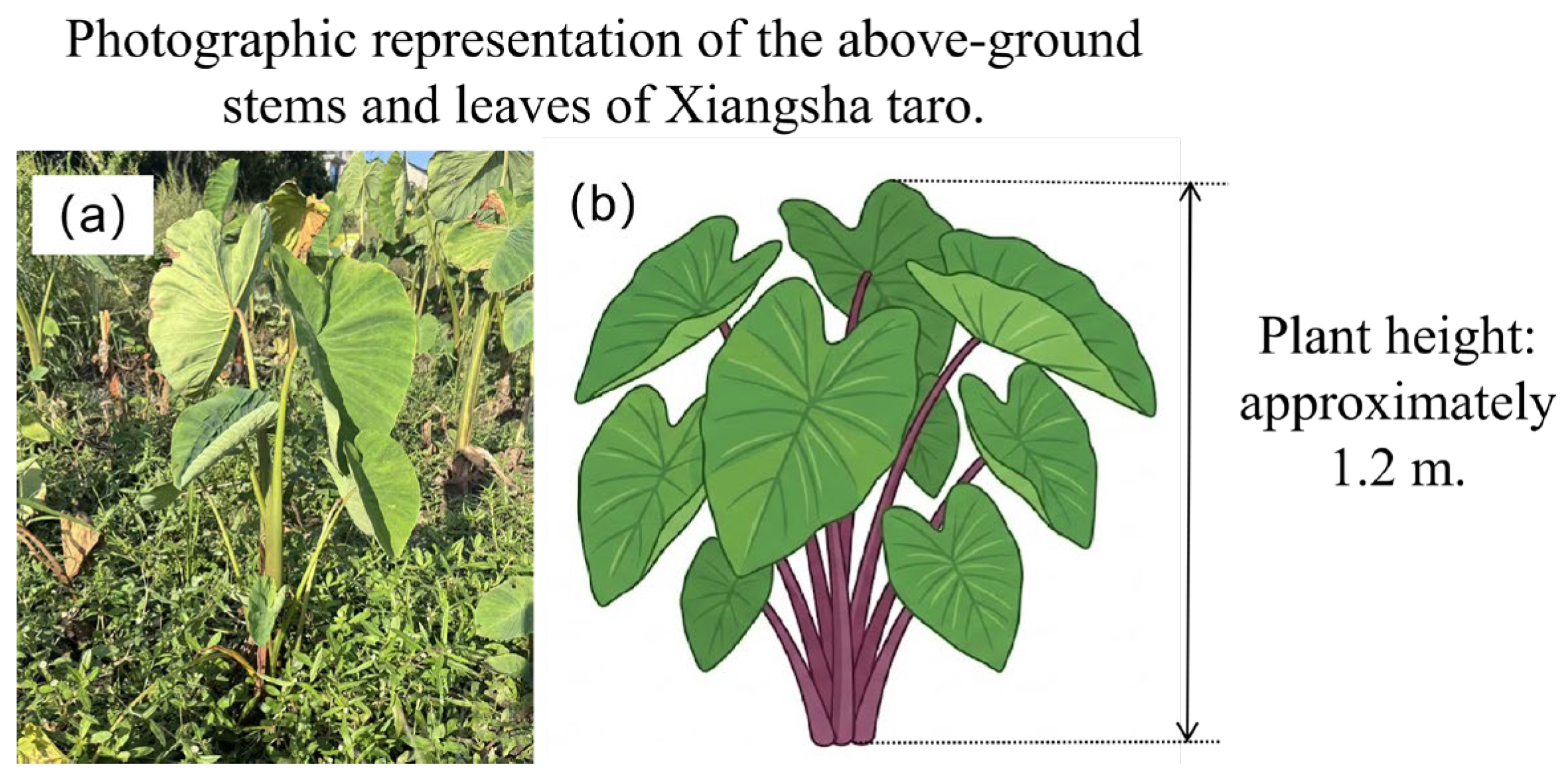
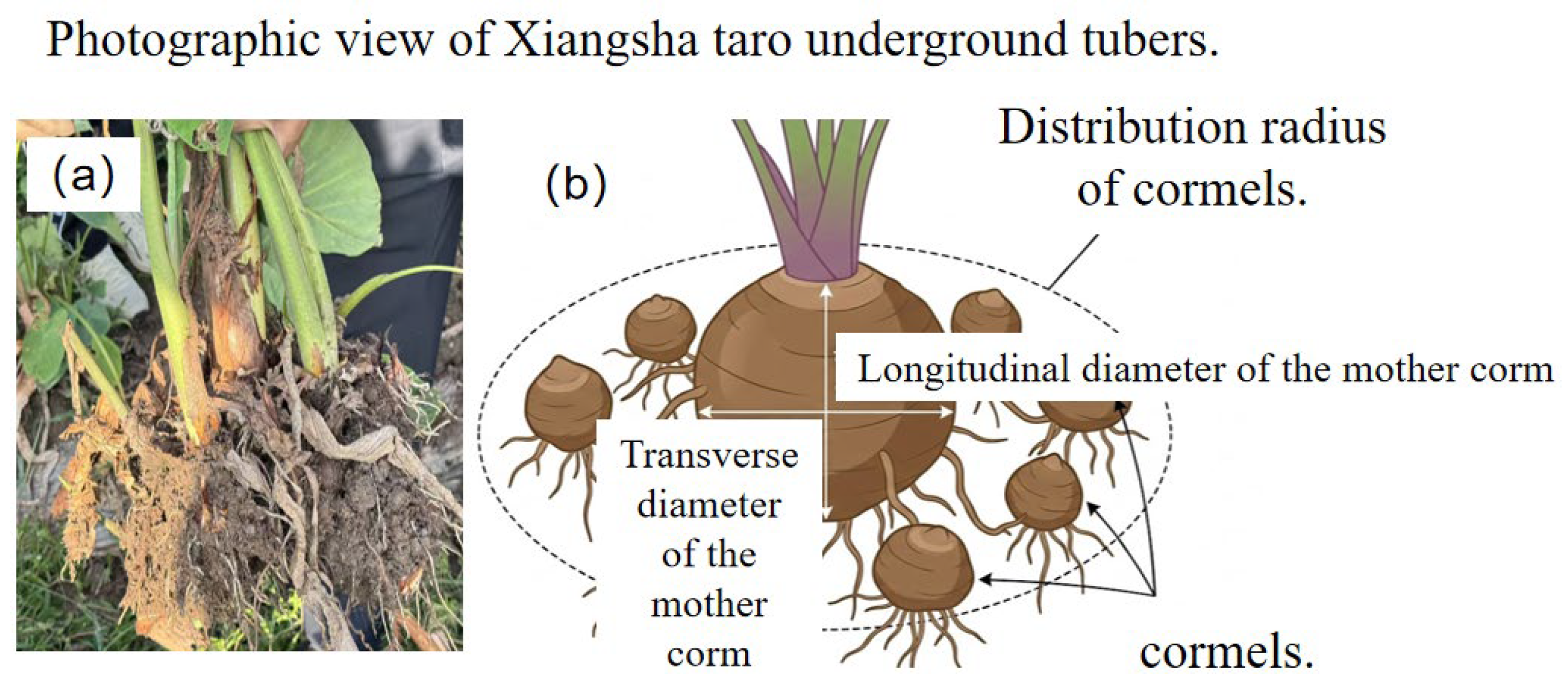
The subject of this study is the Jingjiang Xiangsha taro, which belongs to the genus Colocasia in the family Araceae and is a perennial herbaceous plant. The variety exhibits an upright growth habit with a plant height of approximately 120 cm, featuring 14–16 green leaves supported by purplish-red petioles. The underground tuber system of Xiangsha taro is composed of a corm (mother taro), cormels (daughter taro), and secondary cormels (granddaughter taro). The mother taro is nearly spherical, while the daughter and granddaughter taros range from elliptical to ovoid shapes. Each plant typically yields 8–9 daughter taros, displaying a characteristic “red bud and dense node” morphology. The structural and external features of Xiangsha taro are illustrated in Figure 1 and Figure 2.
The seeding rate for Xiangsha taro is approx. 1875–2250 kg/ha. For mechanized ridge cultivation, a single-row staggered planting pattern is adopted. The cultivation dimensions include a wide-row spacing of 100–110 cm, a narrow-row spacing of 35–40 cm, and a plant-to-plant spacing (hole distance) of 33–35 cm, with one plant per hole, resulting in a planting density of 2900–3900 plants per mu (approx. 43,500–58,500 plants/ha). Generally, harvesting occurs in mid-to-late November when the above-ground stems turn yellow or wither completely. When harvested for commercial use, the daughter taros are separated from the mother taro, while ensuring the daughter and granddaughter taros remain connected to minimize wounding. For seed taro harvesting, it is recommended to extract the entire plant with the surrounding soil intact.
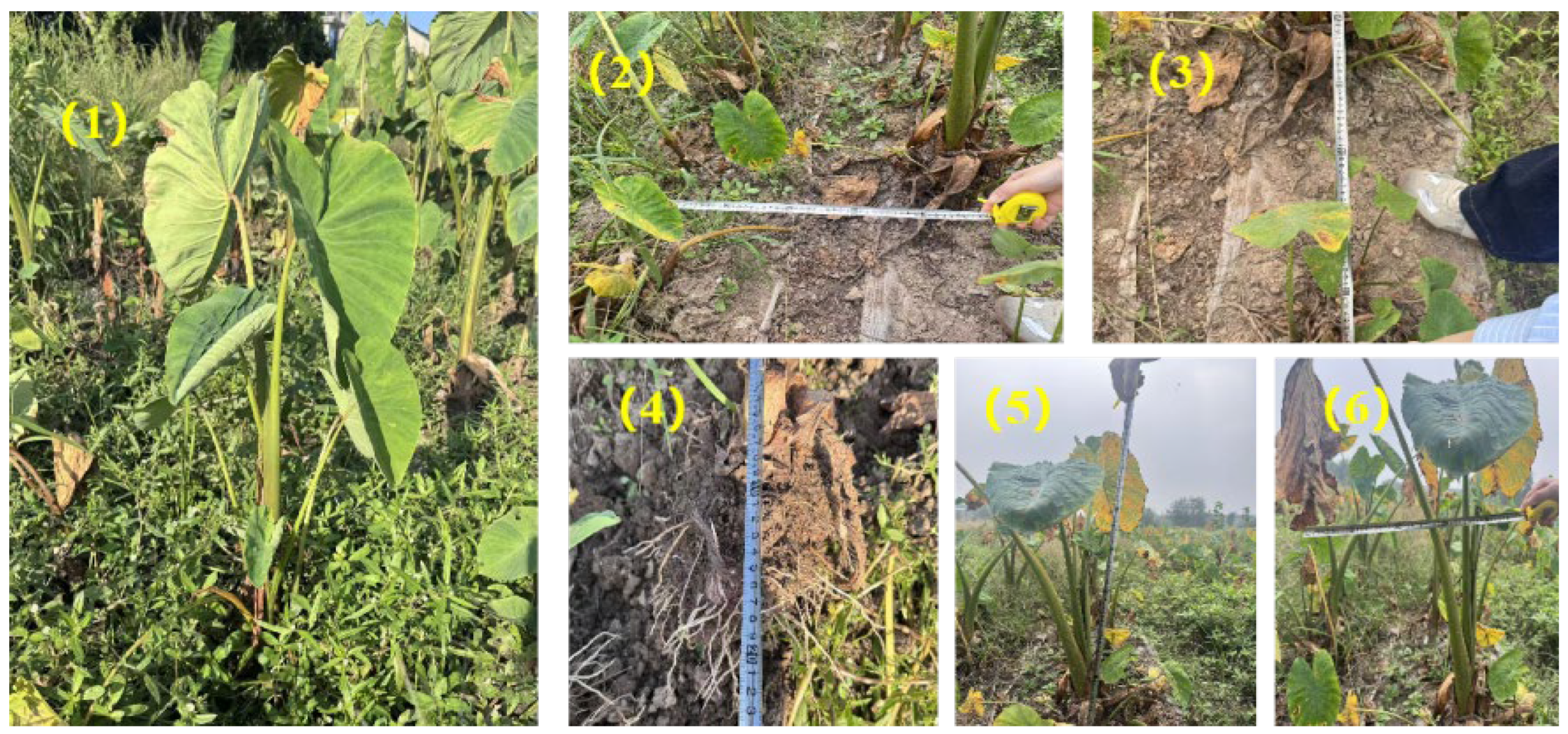
Field investigations were conducted at the Jingjiang Xiangsha taro planting base. As illustrated in Figure 3, the typical cultivation pattern of Xiangsha taro features a wide-row spacing of 100–110 cm, a narrow-row spacing of 35–40 cm, and a plant-to-plant spacing (hole distance) of 33–35 cm. To optimize the design of the core functional components of the Xiangsha taro harvester, it is essential to systematically measure key geometric parameters, including plant height (H), stem diameter (D1), petiole base diameter (D2), and leaf spread (D3). During field sampling, plant height (H) and leaf spread (D3) were manually measured using a standard steel measuring tape with a precision class of 1 mm. The stem diameter (D1) and petiole base diameter (D2) were measured utilizing a digital vernier calliper with a precision of 0.01 mm. The high-precision numerical values reported in the subsequent statistical summaries represent the calculated arithmetic means derived from these replicate measurements. Statistical analysis was performed on the measured data to determine the distribution ranges and variation patterns of the geometric characteristic parameters for both the plants and tubers of Xiangsha taro.
To provide accurate boundary parameters for the theoretical cutting model and to elucidate the failure mechanisms of the vascular bundles, the physical and biomechanical properties of the Xiangsha taro stems were quantitatively evaluated. The moisture content of the stems was determined using the standard oven-drying method [25,26]. Fresh stem samples extracted from 10 cm above the ground were weighed using a precision analytical balance and then dried in an electric thermostatic drying oven at 105 °C for 24 h until a constant mass was achieved. The mechanical properties, specifically the shear strength and fibre toughness, were measured using a universal material testing machine equipped with a specially designed double-shear test fixture. The loading speed was uniformly set to 50 mm/min. It is important to acknowledge that this quasi-static testing regime 50 mm/min differs from the high-speed dynamic impacts 480–550 r/min experienced in the field. Biological materials typically exhibit strain-rate hardening under dynamic loads, meaning their apparent shear strength increases. Consequently, the properties determined quasi-statically serve as a conservative baseline. Furthermore, while samples were extracted consistently at 10 cm above the ground, the mechanical properties of the stem may exhibit vertical gradients. Future biomechanical profiling should capture a continuous gradient to account for variations in cutting height caused by field microrelief. The shear strength was calculated as the ratio of the peak shear force to the total cross-sectional area of the stem. Furthermore, the fibre toughness, characterized by the specific fracture energy, was obtained by calculating the integral area under the force–displacement curve during the transient fracture process of the vascular bundles.
Furthermore, to provide explicit experimental boundary inputs for the kinematic friction model, the dynamic friction coefficient and friction angle between the Xiangsha taro stems and the blade material were determined. An inclined-plane sliding test apparatus was utilized. Fresh stem samples were placed on a test plane constructed from spring steel. One end of the steel plane was gradually elevated at a constant rate until the stem sample initiated steady downward sliding. The critical inclination angle at the moment of slip was recorded as the friction angle. The inclined-plane sliding test was repeated 15 times for statistical reliability. The tests yielded an arithmetic mean friction angle of 24.3° with a standard deviation of 2.1°. To ensure the determinism of our analytical model, this specific mean value of 24.3° was directly incorporated as a core input parameter into the theoretical sliding-cutting equations, replacing the generic range.

2.2. Physical Properties of Soil for Xiangsha Taro Cultivation

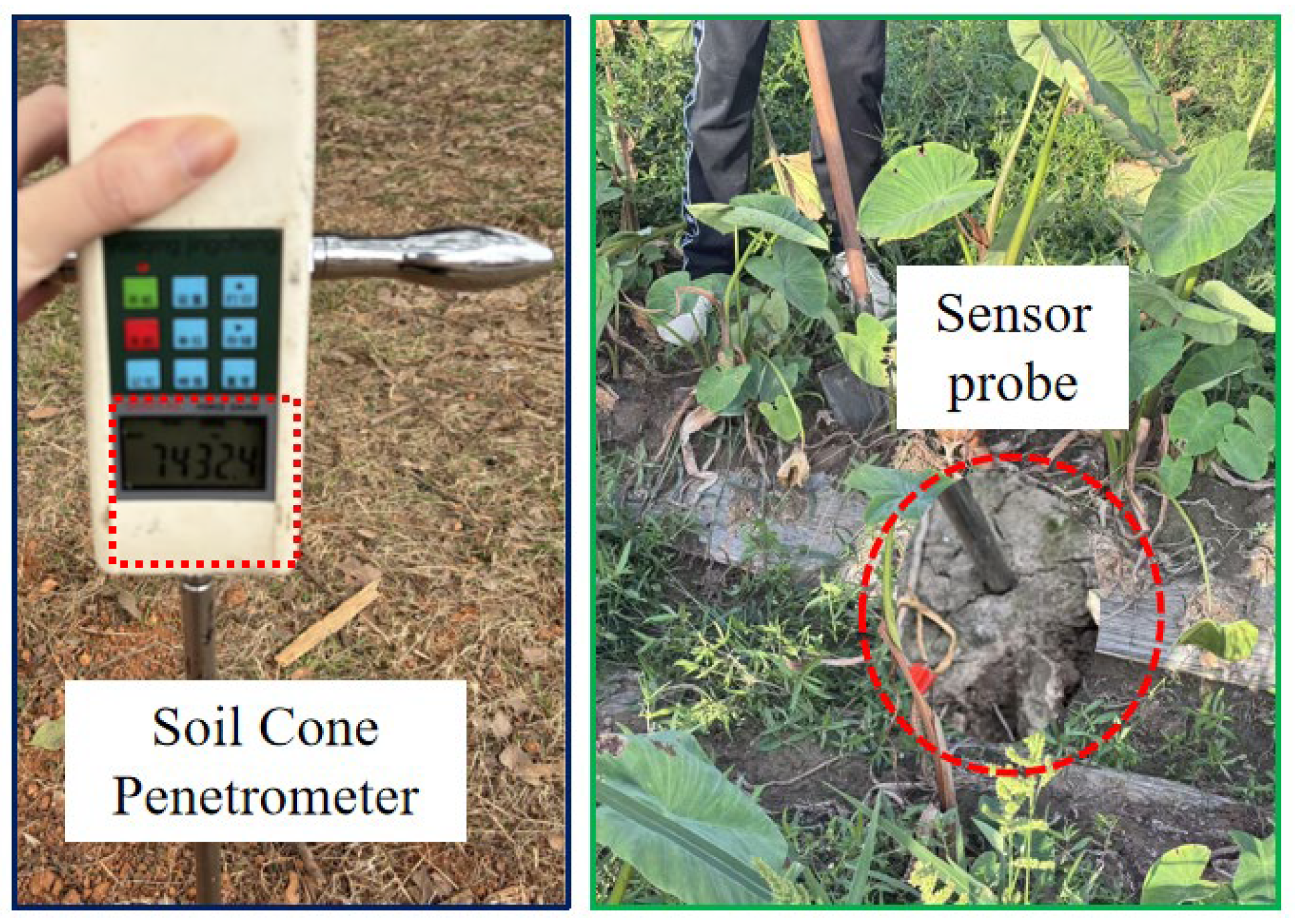
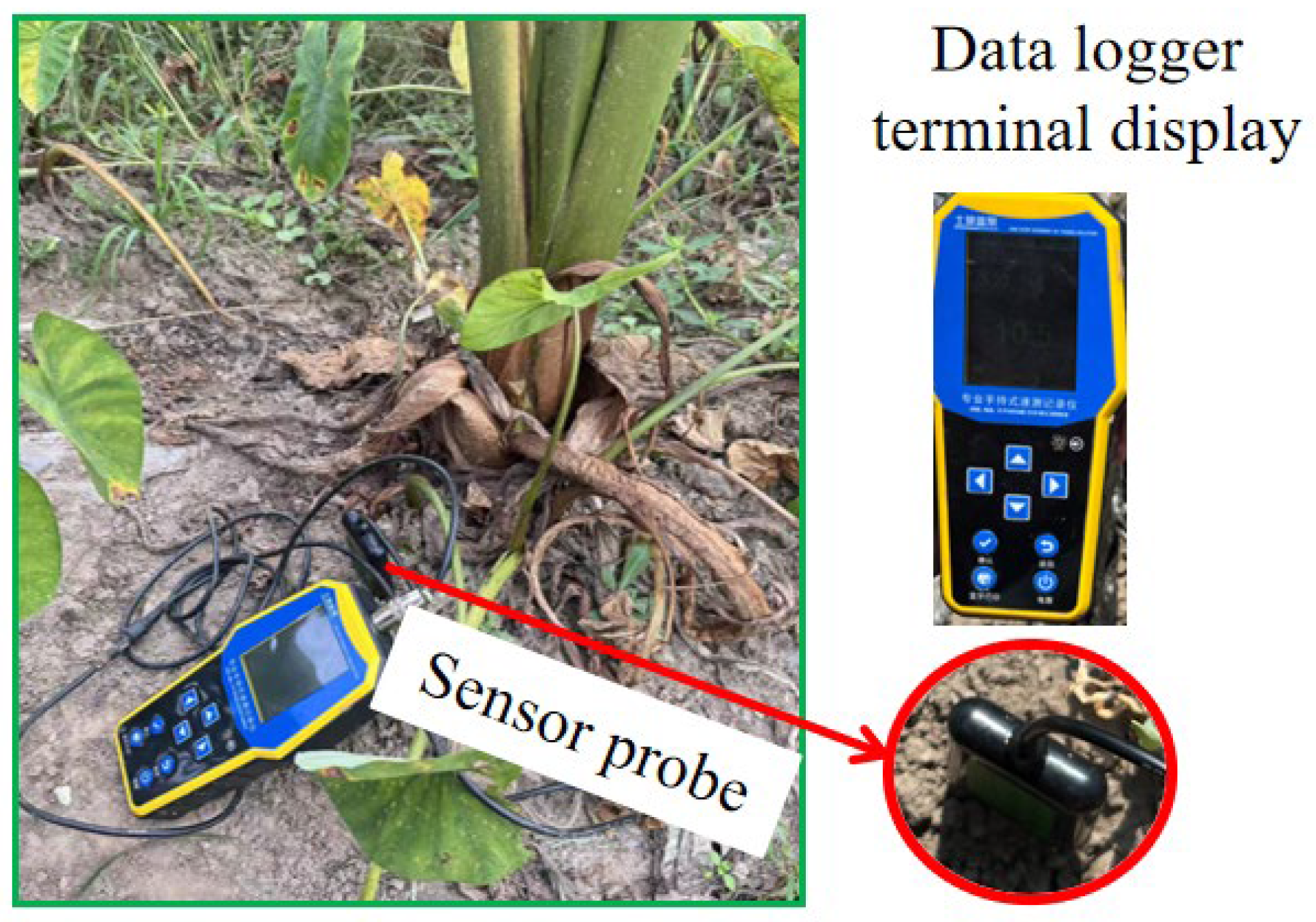
The physical properties of soil exert a critical influence on the efficiency and performance of mechanized Xiangsha taro harvesting. Accurate characterization and systematic measurement of these properties are essential for optimizing the structural design of key functional components in the harvester, thereby enhancing harvesting efficiency while minimizing tuber damage and soil compaction issues. Soil physical properties primarily encompass parameters such as soil texture, bulk density, moisture content, and soil penetration resistance (SPR) [27,28,29]. The specific field measurement procedures are illustrated in Figure 4 and Figure 5.
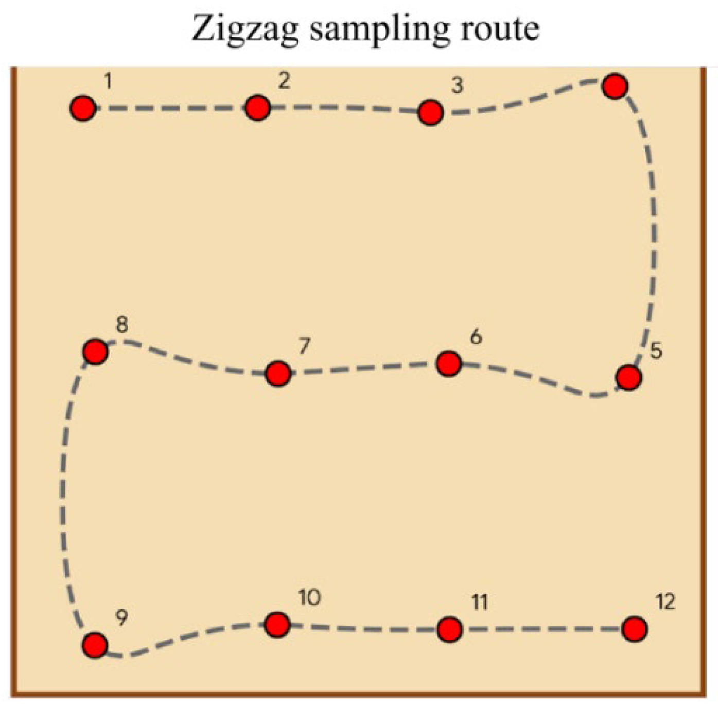
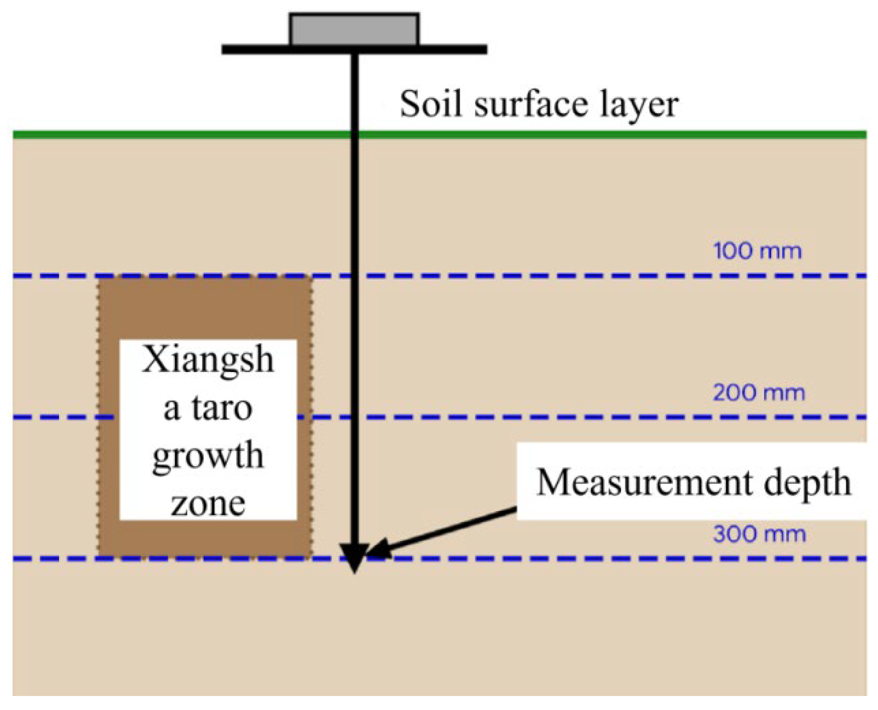
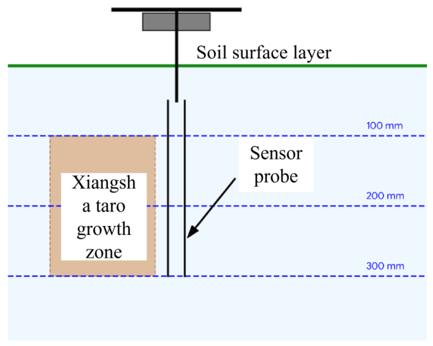
Based on the vertical distribution characteristics of Xiangsha taro tubers, which primarily grow at depths of 100–300 mm, a stratified measurement scheme was designed for three representative depth layers: 100 mm, 200 mm, and 300 mm. This stratified approach accurately reflects the soil mechanical impedance characteristics within the primary growth zone of the tubers, providing a critical basis for optimizing the soil entry angle, surface curvature, and vibration parameters of the digging shovel. As illustrated in Figure 6 and Figure 7, twelve measurement points were randomly selected across the field following a Zigzag sampling route. A digital soil penetration resistance metre was employed to determine the soil compaction at each specified depth [30].
Soil moisture content is a pivotal physical parameter characterizing the degree of soil wetness and serves as a core factor influencing the efficacy and efficiency of mechanized Xiangsha taro harvesting. An optimal soil moisture level not only helps maintain moderate adhesion between the tubers and the surrounding soil—thereby ensuring the physical integrity of the tubers during extraction—but also effectively reduces the operational resistance of the digging apparatus, enhancing overall harvesting productivity.
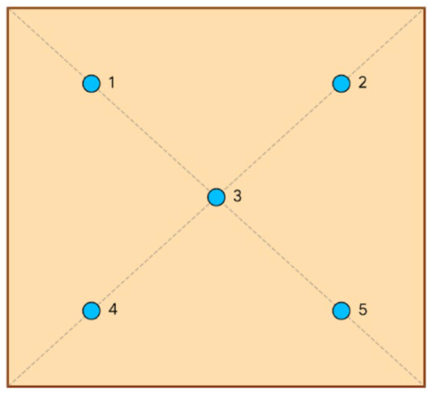
To accurately assess the soil moisture status within the Xiangsha taro growth zone, this study employed a TDR-350 soil moisture metre. Measurement points were arranged across the experimental plots following the standard five-point sampling method. To ensure the statistical robustness and high reliability of the dataset across the test site, this five-point sampling procedure was repeated to obtain 12 independent replicate measurement sets. Systematic measurements of soil moisture content were conducted at three representative depth layers: 100 mm, 200 mm, and 300 mm for each replicate set. The measurement procedures are illustrated in Figure 8 and Figure 9.

2.3. Design and Force Analysis of the Cutting Tool

In the mechanized harvesting of Xiangsha taro, the cutting tool serves as the critical terminal component directly addressing canopy obstacles. Its cutting performance fundamentally determines the efficiency of stem removal and the safety of the underground tubers. The Xiangsha taro stem exhibits typical characteristics of a non-homogeneous composite material: the periphery is encased in dense epidermal tissue, while the internal ground tissue consists of parenchyma cells with large intercellular spaces. Crucially, the vascular bundles, which provide the primary mechanical support, are arranged in a dense annular pattern. This unique microstructure endows the Xiangsha taro stem with exceptional flexibility and tensile strength.
If traditional direct-impact cutting is employed, the blade tip is highly susceptible to causing severe compressive deformation of the brittle parenchyma cells at the moment of contact. Furthermore, it is difficult to swiftly sever the tough clusters of vascular bundles. This not only leads to a sharp increase in cutting resistance but also causes unsevered stems to exert violent tearing forces and vibrations on the underground root system, thereby increasing the tuber damage rate. To mitigate these issues, this device utilizes a multi-tooth rotary disc blade as the executive component. The design aims to leverage the sliding-cutting effect generated by high-speed rotation to achieve transient shear failure of the resilient vascular bundles.
To ensure power reliability and focus the study on the cutting mechanism, the baseline power and transmission platform utilized integrated commercial components. Specifically, a commercial backpack brushcutter chassis was employed, powered by a standard 140FA 4-stroke gasoline engine (Huasheng Zhongtian Machinery Group Co., Ltd., Linyi, China), nominal rated power 1.25 kW at 6500 r/min. The torque is transmitted through its original centrifugal clutch (engagement speed ~3000 r/min) and flexible shaft to a terminal right-angle bevel gearbox with a fixed reduction ratio of 1.35:1.
Conversely, the cutting executive component was explicitly designed and developed as the core original contribution of this study. The disc was parameterized to match the structural characteristics of Xiangsha taro and fabricated via CNC laser cutting from 65 Mn spring steel sheet. To withstand high-speed impacts and the abrasive viscoplastic soil environment, the blade teeth were subjected to localized high-frequency induction quenching, achieving a surface hardness of 45–50 HRC. The precise geometric parameters of this uniquely designed disc include an outer diameter of 300 mm, a thickness of 2.0 mm, 60 serrated teeth, and a specific wedge angle of 18° to optimize cutting sharpness and structural integrity.
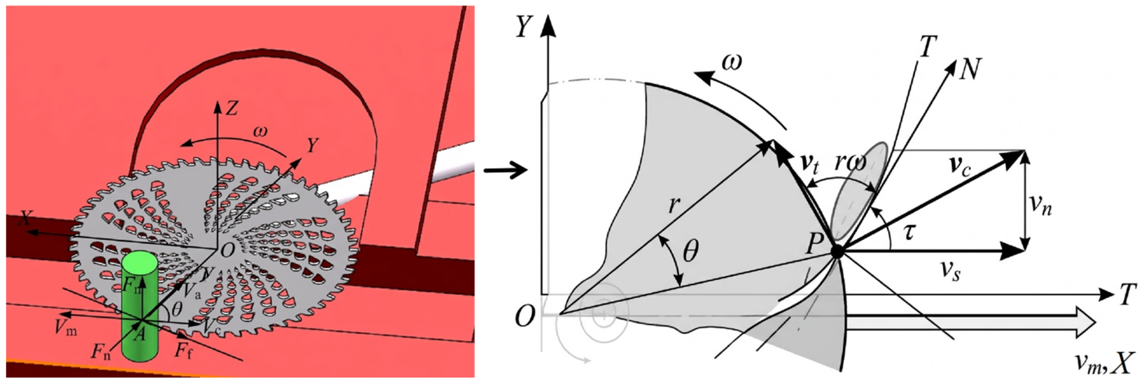
To clarify the mechanical response boundary at the moment the blade cuts into the Xiangsha taro stem, this study establishes a spatial Cartesian coordinate system O-XYZ with an arbitrary differential cutting point P on the blade edge as the origin. As illustrated in Figure 10, the X-axis is aligned with the forward direction of the machine, the Y-axis is coplanar with the rotation plane of the cutter disc and perpendicular to the X-axis, and the Z-axis is perpendicular to the rotation plane, pointing vertically upward. When the cutter disc rotates at an angular velocity ω and the machine advances at a velocity V m , the stem primarily sustains a normal compressive force N and a tangential sliding-cutting force T applied by the blade edge at the moment of contact. Simultaneously, the stem surface exerts a frictional force f on the blade edge along the direction of relative motion. Under ideal sliding-cutting failure conditions, the force system at cutting point P must satisfy specific critical equilibrium requirements to ensure that the blade edge can slide smoothly into the stem tissue without violent exclusion or slippage. The sliding-cutting angle τ is defined as the angle between the tangent direction of the blade edge curve at the contact point and the absolute velocity vector.
The effective sliding-cutting failure force F τ exerted by the blade edge on the stem along the tangential direction, as well as the effective penetration thrust F n along the normal direction, can be derived from the following geometric and mechanical relationships:
F τ = T cos τ N sin τ + f cos τ
F n = N cos τ + T sin τ f sin τ
Among these, the sliding frictional force f between the stem epidermis and the metallic material of the blade edge satisfies Coulomb’s law of friction [31,32]:
f = μ N
In Equation (3), μ represents the dynamic friction coefficient between the epidermis of the Xiangsha taro stem and the material of the blade. By substituting the Coulomb frictional force into the equation for the effective normal thrust F n , the following is obtained:
F n = N cos τ + T sin τ μ N sin τ
that is
F n = N ( cos τ μ sin τ ) + T sin τ
To achieve ideal sliding-cutting operations for Xiangsha taro stems, the primary condition is that the blade’s normal direction must not exert a resultant force that repels the stem outward. This requires the effective normal penetration thrust F n to dominate, ensuring the blade embeds into the stem interior. Under critical conditions, the normal slip resistance component must be less than or equal to the grip component provided by friction. Let the friction angle be ϕ , where μ = tan ϕ . To prevent thick, circular stems from slipping outward in front of the blade edge, the selection of the sliding-cutting angle τ must satisfy:
τ > φ
Once the blade successfully penetrates the epidermis, the cutting resistance primarily stems from the shear resistance required to sever the internal annular vascular bundles. According to the shear failure criterion in mechanics of materials, the absolute resultant cutting force F c provided by the blade edge at the differential cutting point P within the X Y plane must exceed the shear strength limit τ max of the vascular bundle aggregate:
F c = F τ 2 + F n 2 τ max A s
In Equation (7), A s represents the equivalent shear area of the blade cutting through the vascular bundle zone instantaneously, mm2; τ max denotes the average shear strength of the Xiangsha taro stem vascular bundles, MPa, a value that can be referenced from the physical property test data in Section 2.
Increasing the sliding-cutting angle τ can effectively enhance the tangential sliding-cutting force F τ , which is highly advantageous for tearing the exceptionally tough vascular bundle tissues. However, if the value of τ is excessively large, it will weaken the normal penetration thrust F n , making it difficult for the blade edge to rapidly cut through the moisture-rich parenchyma cell zone at the centre of the stem. Therefore, incorporating the previous measurement results of the dynamic friction coefficient for Xiangsha taro stems (with the measured friction angle ϕ set at approximately 20–28°), this design comprehensively balances cutting sharpness with penetration stability. The design threshold for the blade sliding-cutting angle τ is initially established within the range of 35–45°. This parameter combination enables the effective severing of vascular bundle clusters while minimizing the disturbance stress transmitted to the underground tubers during the cutting process.
In actual field operations, the cutting of Xiangsha taro stems by the blade edge is not a static compression process but a complex combined cutting motion resulting from the coupling of the machine’s translation and the cutter disc’s rotation. To analyze this, an absolute coordinate system is established at any differential point P where the blade edge contacts the stem epidermis. Let V m be the translational velocity of the machine along the forward direction, R the operational radius of the cutter disc, and ω the angular velocity of self-rotation. According to the kinematic principle of vector synthesis, the magnitude of the absolute resultant linear velocity V e at the moment the differential point P cuts into the stem can be expressed as:
V e = V m 2 + ω R 2 + 2 V m ω R cos θ
In Equation (8), θ represents the angle between the rotation radius of the cutter disc at the differential point P and the forward direction of the machine, measured in degrees.
The components of the absolute velocity V e along the normal and tangential directions of the blade edge curve, respectively, determine the penetration thrust of the tool into the fibrous tissue and its sliding-cutting severing capability. By defining the normal penetration velocity as V n and the tangential sliding velocity as V s , the kinematic sliding-cutting angle τ , which characterizes the sharpness of the cutting edge, satisfies:
τ = arctan V s V n
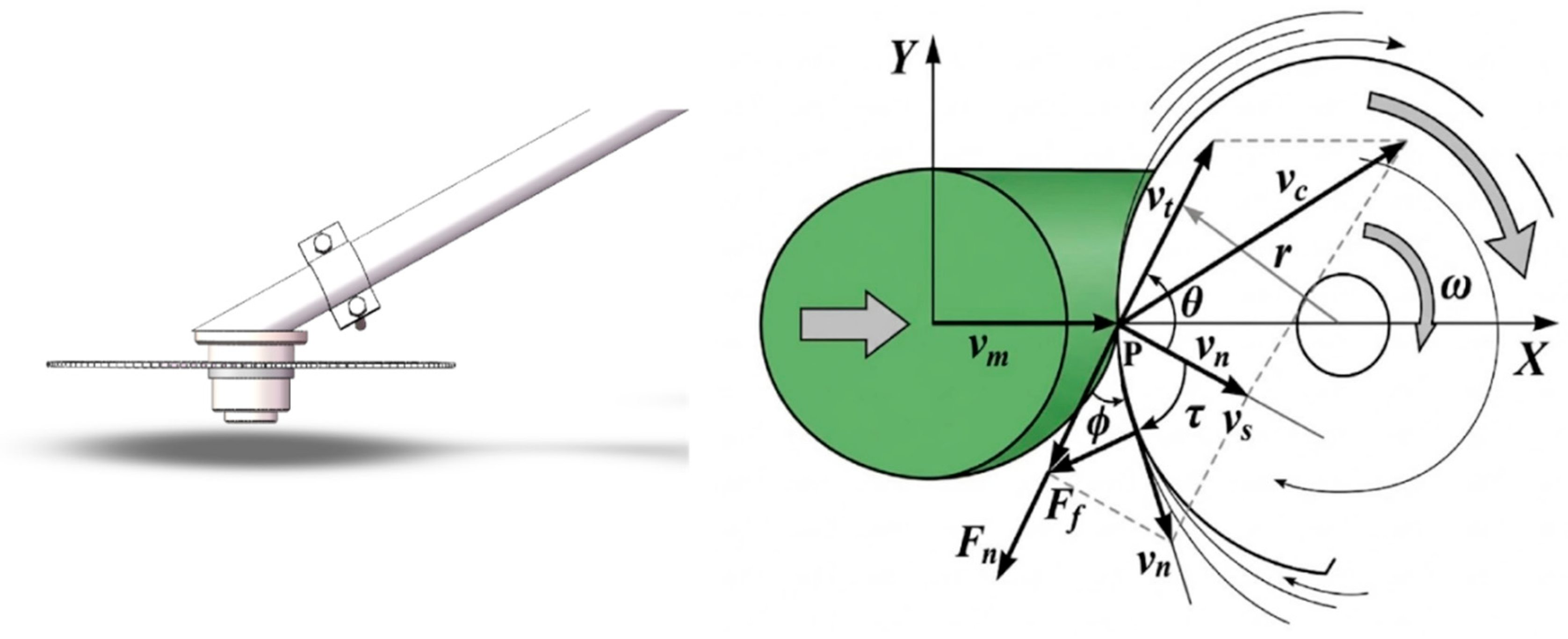
From the perspective of sliding-cutting force mechanics, the cutting resistance exerted by the stem surface on the blade edge primarily consists of the normal compressive resistance N and the tangential frictional resistance f. According to the Coulomb dry friction assumption and the geometric morphology of the cutting edge, to ensure the blade slides smoothly into the tissue without generating a repulsive slip component that pushes the stem outward, the boundary condition requiring the effective normal thrust F n to be greater than zero must be satisfied:
F n = N cos τ μ sin τ > 0
This means the kinematic sliding-cutting angle τ must be strictly greater than the friction angle ϕ between the stem epidermis and the cutter steel material (where μ = tan ϕ ). The force diagram is shown in Figure 11.
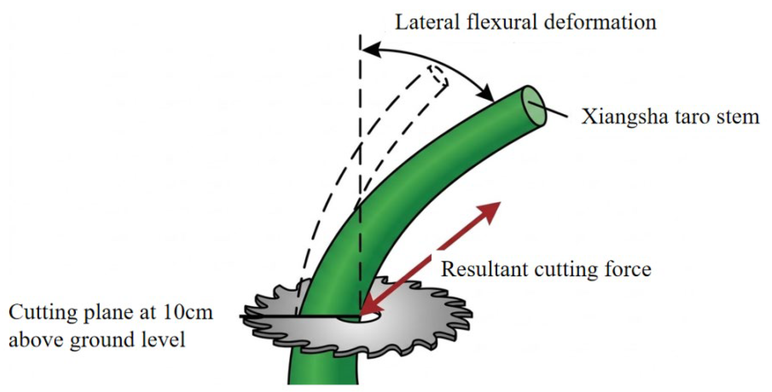
The successful severance of the Xiangsha taro stem is essentially a physical fracture process where the resultant cutting force F c of the blade overcomes the shear strength limit τ max of the vascular bundles. However, at the cutting plane referenced at 10 cm above the ground, the stem does not behave as an absolute rigid body. Instead, it can be modelled as a viscoelastic cantilever beam fixed at one end (with the root anchored in the soil) and characterized by non-linear damping. When the cutting load is applied to the stem by the blade, the transient impact force induces lateral deflection and deformation of the stem. To prevent excessive mechanical thrust during the cutting process—which could lead to the loosening of the underground mother corm or the tearing of its epidermis—a second-order linear forced vibration differential equation is introduced to describe the dynamic equilibrium of the stem at the moment of cutting:
M e q d 2 y d t 2 + C e q d y d t + K e q y = F c x t
In Equation (11): M e q is the equivalent vibration mass of the stem at 10 cm above the ground, kg; C e q is the viscous damping coefficient provided by the internal parenchyma cell meshwork of the stem, N·s/m; K e q is the equivalent bending stiffness of the stem clusters, N/m; y is the instantaneous lateral deflection of the stem at the cutting point, m; and F c x t is the time-varying component of the resultant cutting force in the forward direction of the machine, N. It must be explicitly stated that the vibration differential equation presented above represents a simplified theoretical approach. In reality, the cutting process occurs within viscoplastic soil and involves a highly complex plant architecture consisting of multiple intertwined petioles, rather than a single homogenized cantilever beam. Furthermore, the equivalent damping term primarily models the internal tissue structure, thereby abstracting the highly complex, non-linear energy dissipation introduced by the root–soil interaction during high-speed impact. While this simplified model provides necessary foundational insights into the first-order dynamics of the sliding-cutting mechanism, it does not capture the full fidelity of the multi-body interactions under actual field conditions. To ensure the agronomic requirement of “low-damage residue clearing” the ultimate bending moment M sustained at the soil anchorage point of the stem root must be less than the yield resistance limit M s of the root–soil composite:
M = F c x t H c = 0 H c q x x d x M s
In Equation (12), H c represents the operational ground clearance of the cutter disc (set at 100 mm), and q x denotes the distributed inertial force acting on the stem per unit length, N/m. Schematic of the bending resistance of Xiangsha taro stems. As shown in Figure 12.
Based on the mathematical coupling relationship between Equations (11) and (12), it is evident that the optimal path to mitigate the risk of root damage is to minimize the severance time t and reduce the cutting resistance F c x to the greatest extent possible. This requires that the blades not only possess a sharp wedge angle but also increase the sliding-cutting angle τ by enhancing the angular velocity ω . This ensures that the vascular bundles reach their shear strain limit within an extremely short duration, allowing the cutting process to be completed before any significant macro-deflection y occurs in the stem.
Another core dimension for evaluating the operational performance of the cutting apparatus is the energy transfer efficiency. The total work W t dissipated during the severance of a single Xiangsha taro stem primarily comprises: the fracture work W b required to overcome the shear failure of the vascular bundle clusters; the elastoplastic deformation work W p associated with the compression of internal porous parenchyma cells; and the frictional dissipation work W f between the blade surface and the plant sap or epidermis:
W t = W b + W p + W f = 0 d s τ max A x + E s ε 2 V s + μ N d x
In Equation (13): ds represents the equivalent diameter of the Xiangsha taro stem at the cutting plane, mm; A x is the integral function of the instantaneous cutting area; E s denotes the bulk modulus of the parenchyma tissue, MPa; ε is the local compressive strain; and V s represents the effective volume of the forced deformation zone, mm3. Based on the principle of energy equivalence, when the machine advances steadily at a constant forward velocity V m and cutter disc rotational speed ω , the critical cutting power P c that must be configured for the system is:
P c = W t V m L s
In Equation (14): L s represents the average plant spacing of Xiangsha taro (referencing the agronomic parameter of 330 mm–350 mm). This power constraint equation provides solid boundary input conditions for the subsequent allocation of the overall machine transmission ratio and the selection of the gasoline engine model.

2.4. Design of Blade Operational Trajectory and Leak-Proof Parameters

During the Xiangsha taro harvesting process, the quality of the root-cutting operation directly dictates the efficiency of subsequent digging and collection phases. While the cutting apparatus advances with the machine, the cutting blades undergo high-speed rotational motion. To ensure that each individual Xiangsha taro stem is precisely severed—avoiding phenomena such as missed cuts, plant knock-over, or secondary pulverization—it is imperative to conduct a kinematic modelling analysis on the coordination mechanism between the machine’s forward velocity and the blade’s rotational speed.
An XOZ Cartesian coordinate system is established, with the projection point of the cutter shaft centre at the initial moment serving as the origin O. The forward direction of the machine is defined as the positive X-axis, and the direction perpendicular to the ground pointing upward is defined as the positive Z-axis. Assume that the rotation radius of the cutting blade is R c , the rotational angular velocity of the cutter shaft is ω c , and the forward velocity of the machine is V a .
x = V a t + R c cos ω c t z = R c sin ω c t
Taking the first derivative of x with respect to time t in Equation (15) yields the horizontal velocity component V x of a point on the blade edge:
V x = d x d t = V a R c ω c sin ω c t
To ensure that the blade severs the stems smoothly rather than knocking them over, the absolute trajectory of the blade relative to the ground must exhibit a backward velocity component. Accordingly, the cutting velocity ratio λ is introduced and defined as the ratio of the blade’s peripheral linear velocity V t to the machine’s forward velocity V a :
λ = V t V a = ω c R c V a
An analysis of the blade’s motion states reveals the following:
When λ 1 : The direction of the absolute velocity at the blade edge consistently points forward. Consequently, the blade exerts compressive and pushing forces on the stems, which easily leads to the lodging of Xiangsha taro and a subsequent failure to sever them.
When λ > 1 : A “curled loop” (cycloidal loop) appears in the trajectory. At the instant of contact with the stem, the blade possesses a backward relative velocity, thereby generating tearing and shearing actions.
To ensure that no Xiangsha taro stems are missed within a row, an overlap must exist between the operational areas of two consecutive blades along the forward direction. Assuming that z n blades are installed on the cutter shaft, the time interval between consecutive blades passing through the same operational plane is Δ t = 2 π z c ω c . Within this interval, the feed rate L (forward displacement per blade) must be less than the horizontal cutting arc length S of a single blade at the effective cutting height. In the XOZ plane, let the effective cutting depth be h. Based on the geometric relationships, the equation for the single feed rate L can be derived as follows:
L = V a 2 π z c ω c = 2 π R c z n λ
To ensure the continuity of the cutting process, the following condition must be satisfied:
λ > 2 π R c z n S max
In Equation (19), S max represents the maximum allowable feed rate, which is determined by the planting density and the physical properties of the Xiangsha taro stems and vines.
Considering the shear strength characteristics of the Xiangsha taro stems, an excessively high velocity ratio λ would lead to repetitive cutting of the same section by the blades. This increases energy consumption and causes severe pulverization, resulting in excessive surface mulch that hinders subsequent digging operations. Conversely, if λ is too low, the cutting force will be insufficient. To achieve the optimal cutting state for Xiangsha taro, the coordination between the machine’s forward velocity and the cutter shaft’s angular velocity must satisfy the following synergistic relationship:
ω c = λ V a R c
The cutting process involves not only the overlap of geometric trajectories but also the impact action of the blades on the stems. Taking the second derivative of Equation (15) yields the centripetal acceleration a at a point on the blade edge:
a x = d 2 x d t 2 = R c ω c 2 cos ω c t a z = d 2 z d t 2 = R c ω c 2 sin ω c t
The magnitude of the resultant acceleration vector is a = R c ω c 2 . According to Newton’s second law, the initial impact force F i generated at the instant of contact between the blade and the stem is:
F i m c R c ω c 2
In Equation (22): m c represents the effective cutting mass of the blade, kg.
To ensure that the thick stems and vines of Xiangsha taro are severed instantaneously, rather than evading the cut through bending or deflection, the initial impact force F i must exceed the dynamic shear support force of the stems. This requirement further defines the lower limit of the angular velocity ω c .
On a cutter shaft configured with multiple blades, the overlap Δ D between the trajectories of adjacent blades in the horizontal plane must be considered to eliminate missed cutting zones entirely. According to the kinematic envelope theory, within the interval during which two consecutive blades pass through the same longitudinal section, the forward displacement of the machine (the feed rate L) must satisfy the following geometric constraints to ensure no missed-cut “dead zones” exist at the cutting height h c :
L 2 R c 2 R c h c 2 = 2 2 R c h c h c 2
By incorporating the definition of the feed rate from Equation (23), the maximum allowable forward velocity of the machine, V a max , required to ensure zero missed cuts, can be derived as:
V a max = z c ω c 2 R c h c h c 2 π
This formula provides a theoretical basis for the upper limit of the travel speed during mechanized harvesting. If the travel speed exceeds this threshold, wave-shaped residual stubble will appear in the field.

3. Results and Discussion

3.1. Measurement Results of Xiangsha Taro Stem Geometric Parameters and Soil Mechanical Characteristics

Due to the complex morphology of Xiangsha taro plants during the maturity stage, where the mother corm and cormels exhibit an irregular spherical or elliptical distribution, measurements of the longitudinal and transverse diameters of the mother corm were taken and averaged to serve as representative dimensions to ensure accuracy. Field measurement results indicate that the average plant height of Jingjiang Xiangsha taro at maturity is approximately 120 cm, with a stem diameter of about 2.5 cm, a petiole base diameter of about 2 cm, and a leaf spread of approximately 100 cm. The statistical data for the geometric parameters of Xiangsha taro, including plant height (H), stem diameter (D1), petiole base diameter (D2), and leaf spread (D3), are presented in Table 1.
It should be noted that the morphological design basis presented in Table 1 was built on a limited sample size of randomly selected plants. While this sample is insufficiently large to serve as a comprehensive botanical characterization of the species, it provides an adequate and necessary dimensional baseline (e.g., maximum stem diameter and average leaf spread) for the preliminary geometric and kinematic design of the mechanical cutting device.
The variance values for all measured parameters were relatively small. Notably, leaf spread, a newly added measurement parameter, exhibited a coefficient of variation of 6.9%, which falls within an acceptable range. This confirms a high degree of phenotypic consistency in Jingjiang Xiangsha taro under uniform growth conditions. These comprehensive datasets provide a precise foundation for the design of key harvester components, such as crop dividers and conveying mechanisms. In particular, the leaf spread parameter serves as a critical guide for determining the operational width of the harvester and designing the divider apparatus.
To obtain precise agronomic parameters for the design of the Xiangsha taro stem-cutting device, a systematic measurement of soil penetration resistance (SPR) in the taro fields was conducted. The results are summarized in Table 2. The data indicate that the average SPR at a depth of 100 mm is 869 kPa. This parameter directly dictates the anchorage strength of the Xiangsha taro root system within the soil. During the design of the cutting apparatus, the overturning moment generated by the cutting force components must remain lower than the restorative constraint moment provided by the soil to the roots. The firmness of the lower soil layers provides a “cantilever beam” style fixation base for the stems, ensuring that the plants maintain an upright posture without root loosening under high-speed sliding-cutting impacts.
To ensure the basal buds of the mother corm remain undamaged for subsequent commercial processing, and to prevent the high-speed cutting disc from striking surface clods caused by field micro-relief, the operational cutting height was explicitly set at 100 mm above the ground. During the field trials, rather than relying on manual stabilization, this height was physically maintained by the adjustable gauge wheels mounted on the prototype’s chassis, which passively followed the contour of the ridge. Lower Limit Setting for Angular Velocity: The high soil penetration resistance enhances the rigid response of the plant when subjected to impact. To sever the stem before significant macro-deflection occurs, it is necessary to increase the impact force by elevating the angular velocity (9.33–14.67 rad/s), thereby mitigating the influence of resistance fed back from the soil to the cutting point.
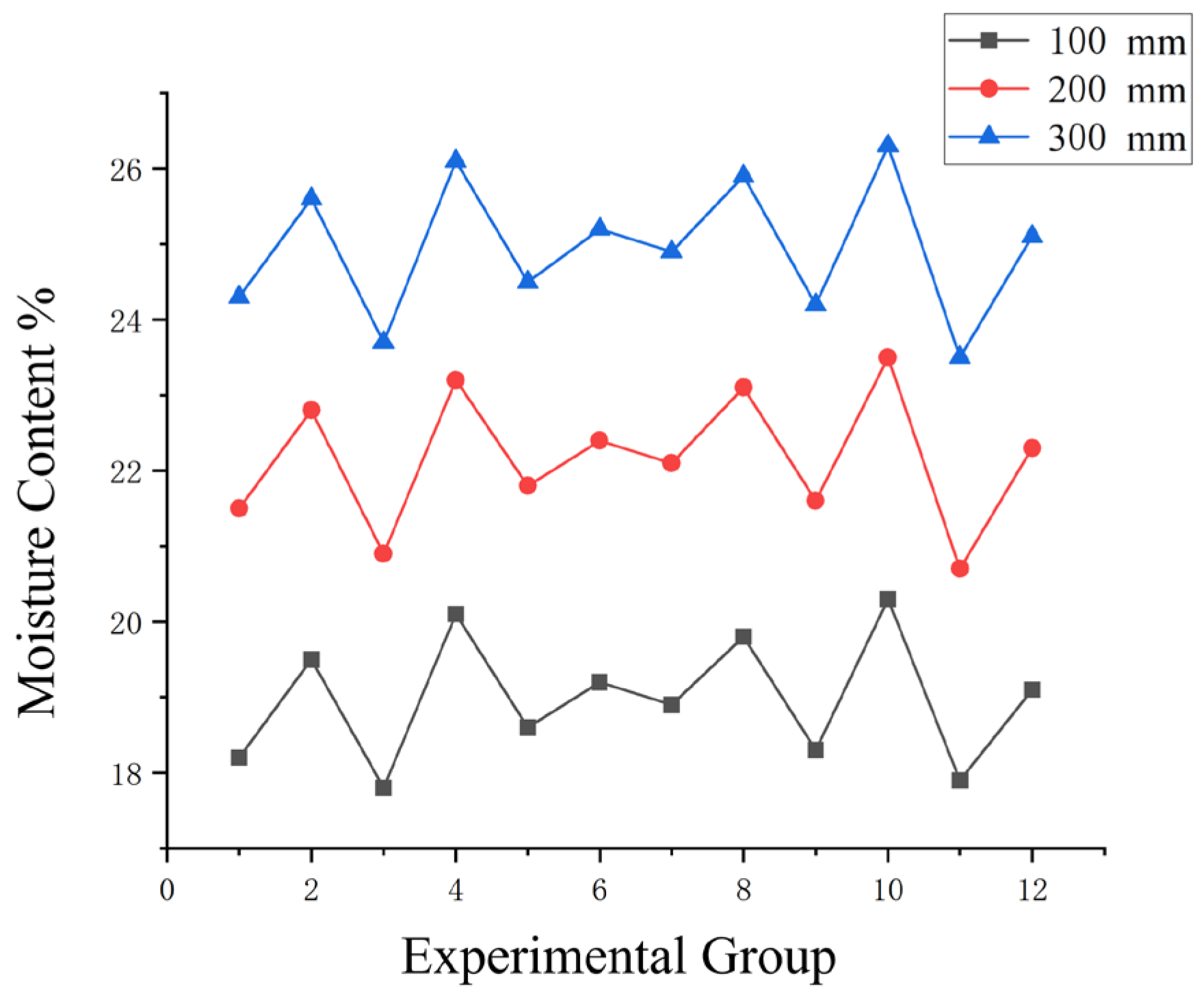
Through stratified sampling and mean data processing, the profile distribution characteristics of soil moisture content in this region were obtained. The specific measurement results are presented in Table 3.
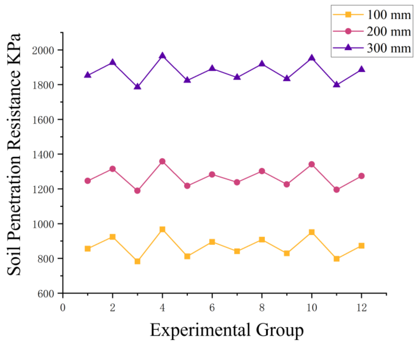
This data systematically reflects the profile distribution patterns of soil moisture content in Xiangsha taro fields. The measurement results indicate a pronounced increasing trend in soil moisture content with depth; specifically, the mean value at a depth of 300 mm (24.93%) is approximately 31.3% higher than that at 100 mm (18.98%). This distribution characteristic is consistent with typical soil moisture movement patterns within a profile. The soil penetration resistance is shown in Figure 13.
The curve graph of soil moisture content is shown in Figure 14. The coefficient of variation for the data within each depth layer is below 5%, suggesting that soil moisture is distributed relatively uniformly across the plot. Notably, the soil moisture content within the primary growth layer of the Xiangsha taro (200–300 mm) remains within the optimal range of 22.07–24.93%.
From a holistic perspective of the data distribution, both soil penetration resistance and moisture content exhibit a significant increasing trend as the detection depth progresses. Specifically, the soil penetration resistance is maintained between 800–1000 kPa at a depth of 100 mm, escalates to 1200–1400 kPa at 200 mm, and reaches 1800–2000 kPa at 300 mm. This indicates that the deeper soil layers possess a more compact structure due to the cumulative overburden pressure from the upper strata. Similarly, the soil moisture content displays a consistent increase with depth, with values at 300 mm being markedly higher than those at the surface. This aligns with the principles of soil moisture dynamics: the surface soil undergoes rapid evaporation due to atmospheric exposure, whereas the deeper layers exhibit superior water retention capacity.
The testing was repeated for 15 samples, and the statistical results are presented in Table 4. The measurement results reveal that the stems possess an exceptionally high moisture content, which exacerbates their susceptibility to structural deflection under compressive loads. Meanwhile, the robust annular vascular bundles exhibit considerable fibre toughness, providing clear experimental justification for the necessity of adopting a high-speed sliding-cutting mechanism rather than a traditional direct-impact approach.

3.2. Analysis of Design Parameters and Operational Trajectories

Based on experimental measurements, the preferred operational velocity ratio λ for cutting Xiangsha taro stems typically ranges from 3.5 to 5.5. Given an average forward velocity of the machine Va = 0.4 m/s and a cutting radius Rc = 150 mm, substituting these values into Equation (19) yields a required rated angular velocity for the cutting blade shaft between 9.33 and 14.67 rad/s.
It is crucial to emphasize that the calculated range of 9.33–14.67 rad/s (approximately 89–140 r/min) represents strictly the kinematic lower limit. This threshold solely ensures the geometric formation of the overlapping cycloidal trajectory required to prevent missed cuts based on kinematics. However, as established in the dynamic analysis (Equation (22)), the highly resilient vascular bundles and high moisture content of Xiangsha taro stems dictate that a successful cut is not merely a geometric problem, but a dynamic fracture process.
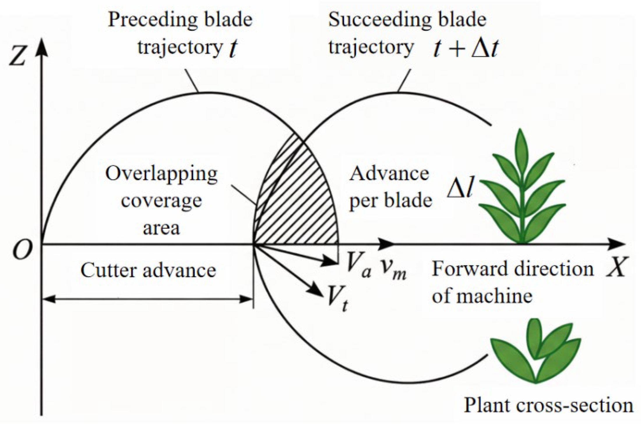
Operating at the kinematic minimum of 14.67 rad/s would fail to provide the transient impact force necessary to overcome the dynamic shear support limit of the stems, leading to severe bending, lodging, or incomplete tearing before severance. Consequently, to fulfil the dynamic shear energy requirements and ensure a clean, instantaneous sliding-cut, the actual experimental rotational speed must significantly exceed this kinematic baseline. Based on these dynamic constraints and preliminary bench test calibrations, the operational rotational speed for the field prototype was designated between 450 and 550 r/min. This practical operational regime inherently over-satisfies the kinematic overlap conditions while providing abundant kinetic energy to achieve the target cutting qualification rate. Schematic of the blade movement trajectories is shown in Figure 15.
In the trochoidal trajectory model, the absolute motion of the blade edge is the result of vector synthesis between the machine’s linear forward velocity V a and the blade’s peripheral rotational velocity V t . When the experimentally determined optimal velocity ratio λ is taken within the range of 3.5–5.5, a distinct “curled loop” (cycloidal loop) region is geometrically inevitable since λ > 1. At the bottom of this loop, the horizontal component of the blade edge’s velocity relative to the ground is opposite to the machine’s forward direction. This implies that the blade strikes and cuts into the stem “head-on” at an extremely high relative velocity, rather than simply pushing against it. This “looping” phenomenon, induced by high angular velocity, is a critical kinematic prerequisite for achieving impact cutting and preventing the stems from being knocked over before severance.
Within the optimal velocity ratio interval, the area of the “overlapping leak-proof zone” (indicated by the shaded part in the figure) is sufficient. Even under complex field conditions—such as uneven plant distribution or slight machine vibrations—this angular velocity range provides adequate kinematic redundancy, ensuring that every Xiangsha taro stem enters the effective cutting envelope of the blades.

3.3. Field Experimental Design and Performance Evaluation System

To validate the efficacy of the aforementioned high-speed sliding-cutting model within an actual operational environment, field harvesting trials were conducted at a large-scale Xiangsha taro cultivation base in Jingjiang, Jiangsu Province. The soil at the test site is characterized as typical viscoplastic soil, with an average moisture content of 23.5% measured in the operational layer via random sampling. The soil penetration resistance aligned with the previously determined gradient distribution patterns.
Due to the mechanical transmission characteristics of the field prototype, the experimental protocol utilized a coupled-parameter evaluation method rather than isolated factorial optimization. The tests focused on evaluating the cutting performance under specific, coupled combinations of the machine’s forward speed (0.35–0.40 m/s) and the cutter disc rotational speed (480–550 r/min). These specific combinations were pre-selected because they dynamically satisfied both the minimum impact energy required for stem severance and the kinematic trajectory overlap. This approach aimed to validate the system’s stability and residue-clearing performance under representative, real-world operational regimes. Within a 30 m test plot, a 5 m acceleration zone and a 20 m stable sampling zone were established. Rotational speed fluctuations were monitored in real-time using high-frequency sensors to ensure the reliability of the experimental data.
During the process of the segmented Xiangsha taro harvesting equipment, the design work was strictly aligned with actual field production conditions, deeply integrating agronomic requirements with mechanical engineering standards. Based on the systematic analysis of Xiangsha taro plant morphology, mechanical properties, and cultivation patterns—and combined with the technical logic of step-by-step harvesting—the core technical parameters for the cutting and digging apparatuses were determined. The key operational indices and anticipated performance metrics for these two units are summarized in Table 5.
Design Rationale for the Cutting Apparatus: The cutting unit is engineered to accommodate the actual morphological conditions of Xiangsha taro stems, which have an average diameter of approximately 25 mm with inherent individual variations; consequently, the operational diameter range is established at 20–30 mm. To achieve high-efficiency clean cutting, the peripheral linear velocity of the cutter disc is set within the range of 8–12 m/s. The primary quality objective is to ensure a cutting qualification rate exceeding 98%, meaning that the vast majority of stems are severed with smooth cross-sections and without critical damage that could impede subsequent processing.
Design Rationale for the Digging Apparatus: The digging unit is designed to cover a depth range of 10–30 cm, encompassing the primary distribution zone of Xiangsha taro tubers. Together, the cutting and digging units constitute the complete workflow of the segmented (step-by-step) harvesting process. Under the aforementioned operational parameters, the overall systemic efficiency is anticipated to reach approximately 0.02–0.033 ha/h.

3.4. Field Experimental Research and Analysis of Xiangsha Taro Stem Sliding-Cutting Performance

To investigate the operational performance of the Xiangsha taro stem-cutting apparatus and to clarify how key parameters influence cutting quality, a specialized field experiment was conducted. Prior to the commencement of the trials, a buffer zone of at least 5 m was reserved at the front of the selected operational area to facilitate machine traversal and adjustment, ensuring the equipment reached a stable working state before entering the designated test section. Operators aligned the device with the ridges according to the field row orientation and calibrated the cutting height to the predetermined value.
The experimental protocol was developed in strict accordance with the performance requirements for cutters specified Technical Conditions for Maize Harvesting Machinery. An evaluation framework was established, centred on core metrics: cutting qualification rate, kerf damage rate, missed cutting rate, and operational efficiency. During operation, monitoring focused on the rotational stability of the cutter disc, the instantaneous dynamics upon contact with the stems, and the post-harvest morphology of the stems.
The calculation methodologies for the specific evaluation indices are as follows:
λ c = N q N t × 100 %
η d = N d N t × 100 %
η m = N m N t × 100 %
E h = L w × W e 10 4 × T × 3600
In the equation: λ c is the cutting qualification rate, %; it refers to the percentage of stems with smooth cross-sections, free from tearing or severe compressive crushing; N q is the number of qualified cut stems, plant; N t is the total number of stems within the measurement area, plant; η d is the kerf damage rate, %; used to evaluate the rupture of the stem epidermis or tissue extrusion caused by cutting; N d is the number of stems exhibiting kerf damage, plant; η m is the missed cutting rate, %; which statistically accounts for the proportion of stems that were either not severed or completely missed; N m is the number of missed stems, plant; E h is the cutting operational efficiency, ha/h; L w is the travel length of the test area, m; W e is the operational width, m; T is the time required to pass through the test area, s.
During the experiment, the machine was powered down immediately after the completion of each test unit. A specified number of consecutive stems within the test segment were randomly selected to measure and record their cutting morphology, followed by a classified statistical analysis of all performance indices. Concurrently, high-speed imaging equipment was utilized to record typical cutting sequences for subsequent analysis of the cutting mechanisms and failure modes. This systematic field trial aims to provide reliable performance data and a basis for the optimization of the cutting apparatus.
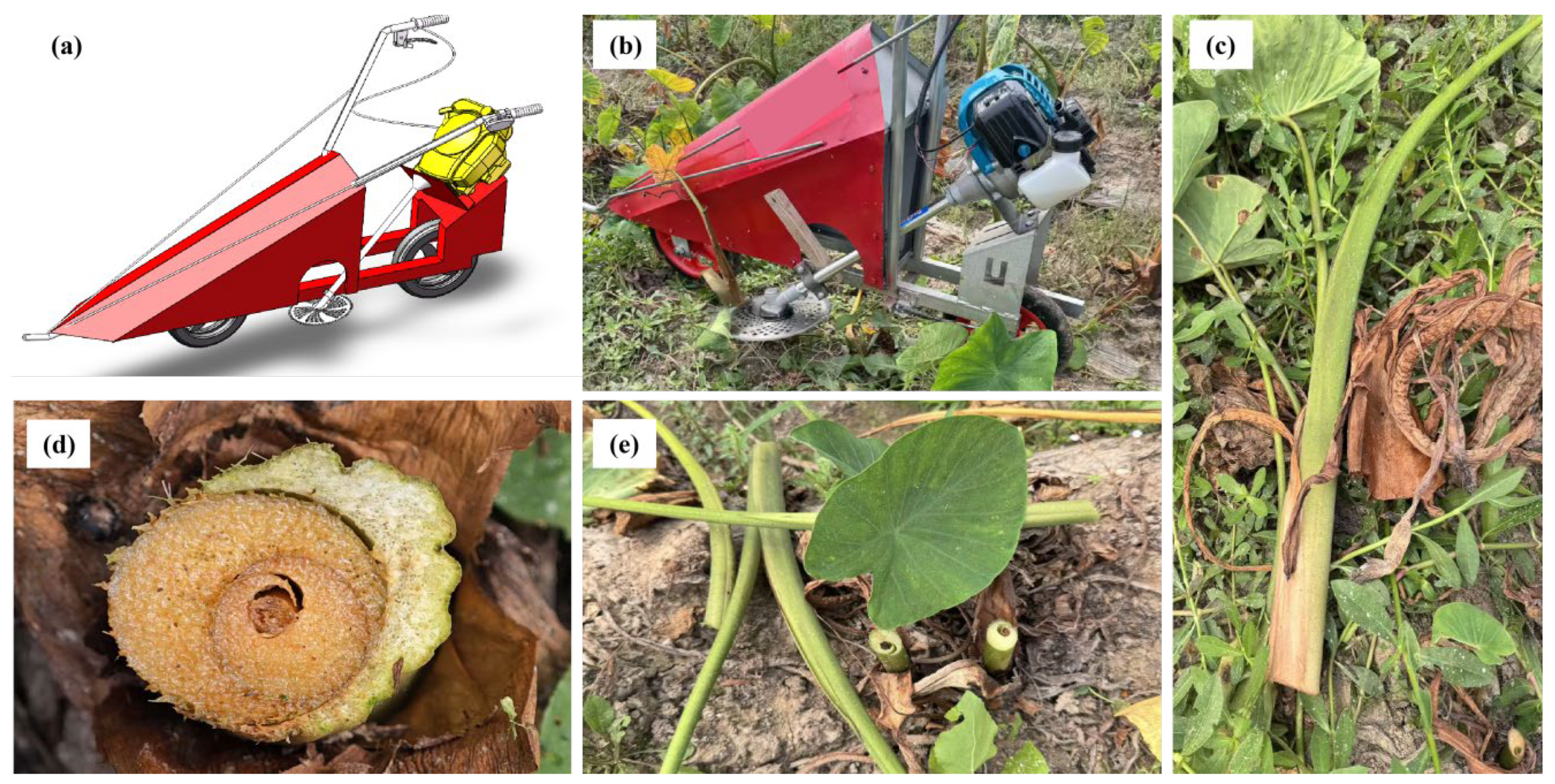
The operational process and the resulting effects of the Xiangsha taro stem sliding-cutting device in the field are illustrated in Figure 16. It is important to note the constructive differences between the 3D CAD model Figure 16a and the field prototype Figure 16b. The CAD model represents the idealized, fully integrated conceptual design envisioned for commercial application, complete with optimized shielding. In contrast, the tested prototype was constructed as a specialized functional test rig. It utilized a stripped-down chassis to strictly isolate and evaluate the dynamic performance of the core cutting mechanism, intentionally omitting the complex upper sheet metal to allow for unobstructed visual monitoring and sensor installation. Preliminary experimental results demonstrate that the cutting unit effectively achieves the “cutting-first” objective of the segmented harvesting process, and its operational performance aligns with the agronomic requirements for Xiangsha taro stem cutting.
The field operational performance of the Xiangsha taro cutting apparatus is jointly influenced by the forward speed and the rotational speed of the cutter disc. Excessive forward speed may result in insufficient cutting duration per individual stem, thereby increasing the risk of missed cuts and irregular cross-sections. Conversely, insufficient rotational speed fails to provide adequate peripheral linear velocity, potentially leading to the compressive tearing of stems rather than clean severance. Integrating the results from preliminary bench tests and dynamic simulations, it was determined that under typical field soil penetration resistance conditions, the optimal forward speed for the device is approximately 0.3–0.4 m/s. At this speed, the cutter disc rotational speed should be maintained between 450–550 rpm, ensuring the peripheral linear velocity of the blade edge remains within the design range of 8–12 m/s. This configuration effectively balances operational efficiency with cutting quality. Furthermore, the cutting height is set at 5–10 cm above the ground, in accordance with agronomic requirements and subsequent digging needs.
Based on the aforementioned cutting performance experimental methodology, critical data—including the number of cut stems, missed stems, and damaged cross-sections within the test area—were collected and statistically analyzed. Subsequently, core performance indices such as the cutting qualification rate, kerf damage rate, missed cutting rate, and operational efficiency were calculated. The field experiment consisted of five replicates, with 80–100 plants per test group. The statistical results of the performance indices are summarized in Table 6.
The optimized data indicate that under the operational parameters of an average forward speed of 0.38 m/s and an average cutter disc rotational speed of 515 r/min, the cutting apparatus achieved an average cutting qualification rate of 96.47%. The kerf damage rate and missed cutting rate were controlled at 2.59% and 0.94%, respectively, demonstrating stable and superior cutting performance. The small standard deviations across all datasets signify high experimental reproducibility and reliable results. The average operational efficiency was 0.025 ha/h, which aligns with the pacing requirements of the segmented harvesting process.
Analysis of the experimental data in Table 6 reveals that the forward speed and cutter disc rotational speed of the cutting unit in the segmented harvesting device jointly influence operational performance. Because the forward speed and rotational speed varied simultaneously across the test groups to maintain specific dynamic configurations, the data reflects the performance of the integrated system rather than the isolated effects of single variables. Under these coupled representative regimes, the system demonstrated highly stable core metrics. While a moderate increase in operational speed enhances efficiency, a slight upward trend in the kerf damage rate was observed. This may be attributed to more concentrated forces acting on the stems per unit time and a more abrupt cutting process. Notably, across the five experimental groups, the cutting qualification rate remained stable within a high-level interval of 95.79% to 96.74%, indicating that the cutting apparatus maintains consistent cutting quality and performance robustness even under parameter fluctuations.
It is important to transparently note that while the field trials demonstrated an average cutting qualification rate of 96.45%, this practical outcome remains slightly below the formulated theoretical design objective of >98% outlined in Table 5. This discrepancy is expected under real-world field conditions. The theoretical > 98% target assumes uniform plant morphology and idealized steady-state cutting. In the actual field, micro-undulations in the soil surface cause slight vertical vibrations of the machine, and natural variations in stem growth angles occasionally cause the blades to strike the stems at sub-optimal angles. Furthermore, the simultaneous variation in forward speed and rotational speed during the trials induced minor transient fluctuations in the velocity ratio. Even though the obtained performance (<97%) safely fulfils the practical agronomic requirements for segmented harvesting, this variance highlights the need for future prototype iterations to incorporate adaptive terrain-following mechanisms to bridge the gap between theoretical design and field reality.
Based on a comprehensive calculation of the average field operational efficiency (0.025 ha/h), the device can achieve a daily coverage of approximately 0.02 ha/h under an 8 h shift. Based on the average field operational efficiency (0.025 ha/h), the device exhibits a promising theoretical daily processing capacity. However, it is crucial to acknowledge that this estimated capacity was achieved under orderly experimental plot conditions with explicit row alignment. In actual agricultural practice, field variables such as plant position deviations, terrain irregularities, and the limited lateral guidance of a rigid row-guided system may reduce this theoretical efficiency. Therefore, while the device demonstrates strong mechanization potential, the exact magnitude of its practical advantage over a human operator equipped with a commercial manual brushcutter requires further validation through controlled comparative studies.
Finally, it should be noted as a limitation that while this study establishes a theoretical basis for reduced root disturbance, the field evaluation strictly quantified above-ground cutting metrics. Direct empirical quantification of subsoil tuber damage and root system displacement remains a critical necessity for future comprehensive studies.

3.5. Field Validation of Cutting Power and Energy Consumption

To experimentally validate the theoretical cutting energy consumption model established in Section 2.3 and to evaluate the actual power requirements under field conditions, dynamic power monitoring was conducted during the harvesting trials. The real-time operational torque and rotational speed of the cutter shaft were recorded using the integrated JN338 digital sensor. The measured cutting power P m was calculated based on the recorded torque T, in N·m and rotational speed n, in r/min using the standard mechanical relationship P m = T n 9550 . To ensure statistical reliability and to cover the operational boundary conditions, 9 groups of field trials with varying forward speeds 0.35–0.40 m/s and cutter rotational speeds 480–550 r/min were executed. The measured power values were then compared with the theoretical power P c derived from Equation (14). The comparative results and the relative errors are presented in Table 7. As indicated in Table 6, both theoretical and measured cutting power exhibit a positive correlation with the machine’s forward speed and the disc’s rotational speed. An increase in forward speed directly elevates the volume of stem biomass processed per unit of time, thereby increasing the continuous fracture work W 1 . Concurrently, higher rotational speeds intensify the transient impact force and frictional dissipation W 2 . The measured average power consumption across the 9 experimental groups ranged from 275.4 W to 362.8 W. The relative error between the theoretical model and the field measurements ranged from 5.20% to 8.81%, with an average error of 6.87%. The measured power was consistently slightly higher than the theoretical prediction. This is structurally expected because the theoretical model calculates the ‘net cutting power’ exactly at the blade interface, whereas the sensors recorded the ‘gross shaft power.’ The minor discrepancy inherently includes the internal mechanical transmission losses of the flexible shaft and bevel gears typically exhibiting an efficiency of ~85%, alongside the complex viscoelastic damping of the soil–root system in the actual field, which were simplified in the theoretical equation. Nevertheless, the strict control of the relative error within 10% strongly verifies the accuracy and reliability of the theoretical energy consumption model, proving its value for guiding the power matching of the 1.25 kW engine equipped on the prototype.

3.6. Comparison with Similar Harvesting Technologies

To further highlight the technical advantages of the developed high-speed sliding-cutting device, its performance was compared with four other typical harvesting methods or devices commonly used for root and tuber crops:
(1)
Traditional Reciprocating Cutters: When processing the high-moisture and highly flexible stems of Xiangsha taro, reciprocating cutters often experience a mismatch between the cutting speed and the forward velocity. This limitation frequently leads to severe structural deflection or complete lodging of stems before severance, resulting in high missed cut rates. In contrast, our device utilizes a “cycloidal loop” trajectory to achieve an absolute backward velocity, successfully maintaining a high cutting qualification rate of 96.47%.
(2)
Direct-Impact Rotary Cutters: Traditional direct-impact mechanisms are highly susceptible to causing severe compressive deformation of the brittle parenchyma cells at the moment of contact. Furthermore, they cause unsevered stems to exert violent tearing forces on the underground root system, increasing the tuber damage rate. The optimized sliding-cutting angle (35–45°) of our device transforms the impact into a transient shear failure, effectively protecting the underground tubers.
(3)
Manual Harvesting Devices: Traditional manual harvesting accounts for the majority of labour input. While our mechanized system achieved an estimated field capacity of 0.025 ha/h, a direct quantitative comparison with an operator using a commercial portable brushcutter under identical field conditions was not conducted in this preliminary study. Future evaluations will focus on comparing the maneuvering flexibility and actual harvest capacities between human-controlled commercial devices and our rigid row-guided system to fully substantiate the operational advantages.

4. Conclusions

  • Plant–Soil Biomechanical Boundaries: A design baseline was established based on the morphology of Xiangsha taro. Within the primary tuber distribution zone, the soil penetration resistance exhibited a 115% depth-dependent escalation. These boundary conditions indicate the potential need for a transient cutting mechanism to overcome viscoplastic soil impedance.
  • Kinematic Innovation of Sliding-Cutting: To overcome the high toughness and deflection susceptibility of the vascular bundles, a high-speed sliding-cutting model was constructed. Integrating a sliding-cutting angle of 35–45° with an optimal velocity ratio of 3.5–5.5 induces a critical “cycloidal loop” trajectory. This kinematic overlap generates an absolute backward velocity that theoretically mitigates forward pushing forces enabling transient shear failure before macro-deflection occurs, thereby indicating a potential to reduce the mechanical stress transmitted to the root system, which serves as a preliminary theoretical basis for minimizing damage to the underground tubers.
  • Initial field validations under controlled row conditions indicated that the evaluated parameter combination yielded a cutting qualification rate exceeding 96%. While the device provides a preliminary solution to the cutting-first technical bottleneck in complex viscoplastic environments, its practical superiority over commercial manual devices requires further rigorous comparative testing. Ultimately, this study offers an initial theoretical model and technical reference for the future development of segmented harvesting equipment.

Author Contributions

Conceptualization, X.H. and Z.T.; methodology, X.H.; software, X.H.; validation, X.H., Q.H. and T.J.; formal analysis, X.H.; investigation, X.H.; resources, X.H.; data curation, X.H.; writing—original draft preparation, M.F.; writing—review and editing, X.H.; visualization, X.H.; supervision, X.H. and J.Z.; project administration, X.H. and J.S.; funding acquisition, X.H. All authors have read and agreed to the published version of the manuscript.

Funding

This research work was supported by the Modern Agricultural Machinery Equipment and Technology Promotion Project of Jiangsu Province (NJ2025-16) and the Taizhou Science and Technology Support Programme (Agriculture) Project (TN202315) and the Postgraduate Research & Practice Innovation Program of Jiangsu Province (SJCX25_2455).

Data Availability Statement

The data used to support the findings of this study are available from the corresponding author upon request. (All the experimental data in the article were collected in 2025).

Conflicts of Interest

The authors declare no conflicts of interest.

References

  1. Sun, W.; Huo, J.Z.; Chen, J.; Li, Z.; Zhang, X.; Guo, L.; Zhao, H.F.; Zhao, Y. Disc cutters’ layout design of the full-face rock tunnel boring machine (TBM) using a cooperative coevolutionary algorithm. J. Mech. Sci. Technol. 2011, 25, 415–427. [Google Scholar] [CrossRef]
  2. Yu, J.; Chu, J.K.; Zhang, M.Q.; Ran, Y.L.; Dong, X.; Gao, H.T.; Ma, Z.; Xu, L.Z.; Liu, Y.B.; Wang, S.; et al. Design and testing of a bionic flexible low-damage tobacco-leaf harvesting mechanism. Rev. Bras. Eng. Agric. Ambient. 2025, 29, e292952. [Google Scholar] [CrossRef]
  3. Cong, C.; Cao, G.; Zhang, J.; Hu, J. Dynamic monitoring of harvester working progress based on traveling trajectory and header status. Eng. Agric. 2023, 43, e20220196. [Google Scholar] [CrossRef]
  4. Du, J.P.; Sun, W.; Guo, X.H.; Simionescu, P.A. Parameter analysis and optimization of the conveying and separation device in an astragalus membranaceus harvester. Ind. Crops Prod. 2025, 232, 121321. [Google Scholar] [CrossRef]
  5. Gao, G.H.; Li, Z.; Zhang, Z.H.; Lu, X.F.; Zhai, S.Y.; Zhu, Z.J. Optimal design of the response surface for the root cutting of a hydroponic lettuce harvesting tool. Proc. Inst. Mech. Eng. Part B-J. Eng. Manuf. 2024, 238, 2152–2162. [Google Scholar] [CrossRef]
  6. Ugur, C.; Bektas, I. Evaluation of Some Physico-Mechanical Properties and Formaldehyde Emission of Ecological Chipboards Produced from Annual Residue Plant Stems. Drv. Ind. 2024, 75, 349–357. [Google Scholar] [CrossRef]
  7. Driesen, E.; De Proft, M.; Saeys, W. Soil Moisture Levels Affect the Anatomy and Mechanical Properties of Basil Stems (Ocimum basilicum L.). Plants 2021, 10, 1320. [Google Scholar] [CrossRef] [PubMed]
  8. Liu, R.Y.; Dong, M.J.; Xiao, Q.; Lv, C.Q.; Zhang, Z.Q. Design, Analysis, and Experiment of an Automatic Lettuce-Harvesting Mechanism. Chin. J. Mech. Eng. 2025, 38, 175. [Google Scholar] [CrossRef]
  9. Yu, T.C.; Chen, J.; Jiang, H.Y. A dual-to-multi-mode end effector: Design, evaluation and optimal mode selection for abnormal leaf removal in hydroponic lettuce. Comput. Electron. Agric. 2026, 246, 111648. [Google Scholar] [CrossRef]
  10. Peruzzi, A.; Martelloni, L.; Frasconi, C.; Fontanelli, M.; Pirchio, M.; Raffaelli, M. Machines for non-chemical intra-row weed control in narrow and wide-row crops: A review. J. Agric. Eng. 2017, 48, 57–70. [Google Scholar] [CrossRef]
  11. Zheng, S.Y.; Zhao, X.G.; Fu, H.; Tan, H.R.; Zhai, C.Y.; Chen, L.P. Design and Experimental Evaluation of a Smart Intra-Row Weed Control System for Open-Field Cabbage. Agronomy 2025, 15, 112. [Google Scholar] [CrossRef]
  12. Ahmad, F.; Adeel, M.; Qiu, B.J.; Ma, J.; Shoaib, M.; Shakoor, A.; Chandio, F.A. Sowing uniformity of bed-type pneumatic maize planter at various seedbed preparation levels and machine travel speeds. Int. J. Agric. Biol. Eng. 2021, 14, 165–171. [Google Scholar] [CrossRef]
  13. Pang, J.; Li, Y.M.; Ji, J.T.; Xu, L.Z. Vibration excitation identification and control of the cutter of a combine harvester using triaxial accelerometers and partial coherence sorting. Biosyst. Eng. 2019, 185, 25–34. [Google Scholar] [CrossRef]
  14. Tian, K.P.; Zhang, B.; Ji, A.M.; Huang, J.C.; Liu, H.L.; Shen, C. Design and experiment of the bionic disc cutter for kenaf harvesters. Int. J. Agric. Biol. Eng. 2023, 16, 116–123. [Google Scholar] [CrossRef]
  15. Huang, X.; Wang, W.W.; Li, Z.D.; Wang, Q.Q.; Zhu, C.X.; Chen, L.Q. Design method and experiment of machinery for combination of seed fertilizer and herbicide. Int. J. Agric. Biol. Eng. 2019, 12, 63–71. [Google Scholar] [CrossRef]
  16. Liu, J.; Ren, J.; Guo, W. Thrust and Torque Characteristics Based on a New cutter-head Load Model. Chin. J. Mech. Eng. 2015, 28, 801–809. [Google Scholar] [CrossRef]
  17. Guo, Y.; Cheng, L.; Long, W.H.; Gao, J.Q.; Zhang, J.F.; Chen, S.; Pu, H.M.; Hu, M.L. Synergistic mutations of two rapeseed AHAS genes confer high resistance to sulfonylurea herbicides for weed control. Theor. Appl. Genet. 2020, 133, 2811–2824. [Google Scholar] [CrossRef]
  18. Qing, Y.R.; Li, Y.M.; Yang, Y.; Xu, L.Z.; Ma, Z. Development and experiments on reel with improved tine trajectory for harvesting oilseed rape. Biosyst. Eng. 2021, 206, 19–31. [Google Scholar] [CrossRef]
  19. Liu, C.C.; Wu, N.; Cheng, G.S.; Wu, F.; Gu, F.W.; Shi, L.L.; Wang, B. Design and Optimization of a Lightweight and Simple Self-Propelled Crawler Potato Combine Harvester. Agronomy 2025, 15, 65. [Google Scholar] [CrossRef]
  20. Liang, Z.W.; Xu, L.Z.; De Baerdemaeker, J.; Li, Y.M.; Saeys, W. Optimisation of a multi-duct cleaning device for rice combine harvesters utilising CFD and experiments. Biosyst. Eng. 2020, 190, 25–40. [Google Scholar] [CrossRef]
  21. Janda, A.; Ooi, J.Y. DEM modeling of cone penetration and unconfined compression in cohesive solids. Powder Technol. 2016, 293, 60–68. [Google Scholar] [CrossRef]
  22. Edmondson, R.N. Past developments and future opportunities in the design and analysis of crop experiments. J. Agric. Sci. 2005, 143, 27–33. [Google Scholar] [CrossRef]
  23. Cui, L.F.; Xue, X.Y.; Le, F.X.; Mao, H.P.; Ding, S.M. Design and experiment of electro hydraulic active suspension for controlling the rolling motion of spray boom. Int. J. Agric. Biol. Eng. 2019, 12, 72–81. [Google Scholar] [CrossRef]
  24. Li, T.; Meng, Z.; Ding, H.; Hou, J.; Shi, G.; Zhou, K. Mechanical analysis and parameter optimization of cabbage root cutting operation. Trans. Chin. Soc. Agric. Eng. 2020, 36, 63–72. [Google Scholar]
  25. Liao, Y.; Chen, L.C.; Pan, S.; He, J.; Yang, W.G.; Wu, Y.D.; Feng, X.P. Status and development of mechanized harvesting technology and equipment for leaf vegetables. Guangdong Nongye Kexue 2019, 31, 77–81. [Google Scholar]
  26. Leszczynski, N. The influence of working parameters of a carrot harvester on carrot root damage. Eksploat. Niezawodn.-Maint. Reliab. 2011, 1, 35–41. [Google Scholar]
  27. Guan, C.S.; Fu, J.J.; Xu, L.; Jiang, X.Z.; Wang, S.L.; Cui, Z.C. Study on the reduction of soil adhesion and tillage force of bionic cutter teeth in secondary soil crushing. Biosyst. Eng. 2022, 213, 133–147. [Google Scholar] [CrossRef]
  28. Han, J.Y.; Liu, C.H. Research on a Method to Measure and Calculate Tillage Resistance of Tractor Mounted Plough. AMA-Agric. Mech. Asia Afr. Lat. Am. 2018, 49, 67–73. [Google Scholar]
  29. Wang, J.W.; Xiang, Y.S.; Wang, C.Y.; Xu, C.S.; Zhu, G.X.; Gu, Z.J.; Wang, J.F.; Tang, H. The Method and Experiment of Kinetic Determination for the Rotary Soil-Engaging Components of Agricultural Machinery Using a Compacting Device in a Paddy Field as an Example. Agronomy 2023, 13, 775. [Google Scholar] [CrossRef]
  30. Jiang, D.; Guan, Z.H.; Jiang, L.; Wu, J.; Tang, Q.; Wu, C.Y.; Cai, Y.J. Experimental Study on the Soil Conditions for Rapeseed Transplanting for Blanket Seedling Combined Transplanter. Agriculture 2024, 14, 310. [Google Scholar] [CrossRef]
  31. Jiang, B.; Jiang, L.; Zheng, M.L.; Zhou, J. Axiomatic Design of High Speed Milling Cutter and Fuzzy Object Element Evaluation for Dynamic Cutting Performance. In Proceedings of the 13th International Manufacturing Conference in China, Dalian, China, 21–23 September 2009; pp. 59–64. [Google Scholar]
  32. Cui, Y.J.; Wang, W.Q.; Wang, M.H.; Ma, Y.D.; Fu, L.S. Effects of cutter parameters on shearing stress for lettuce harvesting using a specially developed fixture. Int. J. Agric. Biol. Eng. 2021, 14, 152–158. [Google Scholar] [CrossRef]
Figure 1. Visual representation of the aboveground stems and leaves of Xiangsha taro. Notes: (a) In-field photograph; (b) Schematic showing measured geometric parameters.
Agriculture 16 01203 g001
Figure 2. Diagram of the underground tuber structure of Xiangsha taro. Notes: (a) In-field photograph; (b) Schematic of the corm and cormels.
Agriculture 16 01203 g002
Figure 3. Characterization of Xiangsha taro morphological traits in the field. Notes: (1) Individual whole-plant of Xiangsha taro; (2) Measurement of inter-row spacing; (3) Measurement of intra-row (plant) spacing; (4) Measurement of tuber (corm) diameter; (5) Measurement of height above ground level; (6) Measurement of leaf canopy spread.
Agriculture 16 01203 g003
Figure 4. In situ test of soil penetration resistance.
Agriculture 16 01203 g004
Figure 5. Measurement of soil moisture content in field.
Agriculture 16 01203 g005
Figure 6. Schematic of the in situ zigzag sampling strategy.
Agriculture 16 01203 g006
Figure 7. Schematic of the vertical measurement depth.
Agriculture 16 01203 g007
Figure 8. Layout of the five-point sampling method in the field.
Agriculture 16 01203 g008
Figure 9. Schematic of vertical measurement.
Agriculture 16 01203 g009
Figure 10. Free-body diagram of the rotary disc cutter.
Agriculture 16 01203 g010
Figure 11. Cross-sectional free-body diagram of the cutting tool.
Agriculture 16 01203 g011
Figure 12. Schematic of the bending resistance of Xiangsha taro stems.
Agriculture 16 01203 g012
Figure 13. Soil penetration resistance curve.
Agriculture 16 01203 g013
Figure 14. Soil moisture content curve.
Agriculture 16 01203 g014
Figure 15. Schematic of the blade movement trajectories.
Agriculture 16 01203 g015
Figure 16. Field operation performance of the Xiangsha taro stem cutting device. Notes: (a) Three-dimensional (3D) CAD model of the sliding-cutting device for stems; (b) Field experiment of the stem sliding-cutting device; (c) Lateral gathering process of the stems post-cutting; (d) Stubble condition in the field after cutting; (e) Sample of a qualified cut surface.
Agriculture 16 01203 g016
Table 1. Geometric parameters of Xiangsha taro stems.
NO.Plant Height
H/cm
Stem Diameter
D1/cm
Petiole Base Diameter D2/cmCanopy Spread
D3/cm
1118.52.41.898.5
2121.22.62.1102.3
3119.82.51.999.8
4122.02.52.0103.5
5118.02.31.797.2
6120.52.62.2101.6
7119.02.41.998.9
8121.52.72.1102.8
Mean120.12.51.96100.6
Variance2.170.020.035.23
Range118.0–122.02.3–2.71.7–2.297.2–103.5
Table 2. Measurement results of soil penetration resistance in Xiangsha taro field.
Soil DepthSoil Penetration Resistance/kPaVariance
123456789101112Mean
100 mm8569247839678128958419088299517988738703618
200 mm12461315118913581217128312381302122613411195127412653206
300 mm18531927178619651824189218411918183319521798188618733685
Table 3. Measurement results of soil moisture content in Xiangsha taro field.
Soil DepthMoisture Content/%Variance
123456789101112Mean
100 mm18.219.517.820.118.619.218.919.818.320.317.919.118.980.71
200 mm21.522.820.923.221.822.422.123.121.623.520.722.322.160.77
300 mm24.325.623.726.124.525.224.925.924.226.323.525.124.930.85
Table 4. Physical and biomechanical properties of Xiangsha taro stems at the cutting plane.
PropertiesMeasurement RangeMean ValueStandard Deviation (SD)Coefficient of Variation (CV/%)
Moisture content (%)86.42–90.1588.541.151.30
Shear strength τ (MPa)1.12–1.451.280.118.59
Fibre toughness/Specific fracture energy 21.85–27.3024.621.747.07
Table 5. Key operational parameters and performance indicators of the sliding-cutting device for Xiangsha taro stems.
Device ModuleKey ParametersDesign TargetsPerformance Expectations
Stem cutting deviceApplicable stem diameter20–30 mmCovers major stem specifications
Cutting linear velocity8–12 m/s
Cutting quality qualification rate>98%
Table 6. Statistical results of field performance indicators for the Xiangsha taro stem cutting device.
Experimental IndicatorsTest Run No.MeanStd. Dev.
12345
Total number of stems (plants)859288959090.03.8
Travel speed (m/s)0.350.380.360.400.370.370.02
Cutter rotary speed (r/min)480520500550530516.027
Qualified cuts (plants)828985918786.83.5
Damaged cuts (plants)232322.40.55
Missed cuts (plants)101110.80.45
Qualified cutting rate (%)96.4796.7496.5995.7996.6796.450.38
Cutting damage rate (%)2.353.262.273.162.222.650.49
Missed cutting rate (%)1.180.001.141.051.110.900.51
Operating efficiency (ha/h)0.0230.0250.0240.0270.0250.0250.02
Table 7. Comparative analysis of theoretical and measured cutting power consumption.
Parameter/Group No.123456789Mean
Forward speed Vm (m/s)0.350.350.350.380.380.380.400.400.40-
Cutter rotary speed n (r/min)480515550480515550480515550-
Theoretical power Pc (W)261.8278.5295.1284.2302.4320.6299.2318.3333.4299.3
Measured power Pm (W)275.4296.2316.7301.5321.8344.3320.1342.6362.8320.2
Relative error (%)5.206.367.326.096.427.396.997.638.816.91
Disclaimer/Publisher’s Note: The statements, opinions and data contained in all publications are solely those of the individual author(s) and contributor(s) and not of MDPI and/or the editor(s). MDPI and/or the editor(s) disclaim responsibility for any injury to people or property resulting from any ideas, methods, instructions or products referred to in the content.