Article

Attitude Stabilization Control Methods for a Tracked Agricultural Transport Platform in Hilly and Mountainous Terrain Based on Adaptive Kalman Filtering


1
College of Engineering, Nanjing Agricultural University, Nanjing 210031, China
2
College of Mechanical and Electronic Engineering, Nanjing Forestry University, Nanjing 210037, China
*
Authors to whom correspondence should be addressed.
Agriculture 2026, 16(10), 1123; https://doi.org/10.3390/agriculture16101123
Submission received: 16 April 2026 / Revised: 13 May 2026 / Accepted: 19 May 2026 / Published: 21 May 2026
(This article belongs to the Section Agricultural Technology)

Abstract

This study proposes an attitude stabilization method based on an improved adaptive Kalman filter (AKF). The aim is to address attitude fluctuations and rollover risks in rail-based agricultural transport platforms on hilly terrain caused by slope changes, load shifts and vibrations. A dynamic model integrating the load distribution and center-of-mass migration was established, and an adaptive noise covariance mechanism was used to precisely estimate the roll and pitch angles in real time. A dual-channel proportional–integral–derivative controller was designed for automatic leveling, and a rollover risk index (RRI) was adopted for safety evaluation. Simulations revealed the ability of the improved AKF to decrease the roll estimation (RMSE) from 1.2684° to 0.8670° and the stabilization time from 0.6250 to 0.3830 s for the roll and from 0.6930 to 0.4110 s for the pitch. Under 10–30° slope disturbances, the average RRI decreased from 0.1861 to 0.1506. Field tests further demonstrated decreases in the peak roll and pitch angles from 4.8° and 4.1° to 3.1° and 2.7°, respectively, and a decrease in the average RRI from 0.203 to 0.169. The improvements in estimation accuracy, leveling performance, and operational safety under complex disturbances indicate the strong engineering potential of the proposed method.

1. Introduction

Hilly and mountainous regions are key areas for China’s distinctive and high-efficiency agriculture; however, agricultural mechanization is constantly limited by constraints such as terrain variations and complex road conditions and logistics [1,2]. In orchards and terraced fields or similar typical settings, agricultural machinery and supplies often rely on slope tracks or rudimentary transport facilities [1,3]. During operation, transport equipment is susceptible to sudden changes in slope gradient, load variations, and mechanical vibrations, which cause the platform to experience attitude fluctuations or overturn accidents. Therefore, research on stability control methods holds significant engineering value.
In recent years, rail-based transport systems have been gradually adopted for mountainous agricultural transport because of their well-defined path constraint mechanisms, strong climbing ability, and high operational efficiency [1,2,3]. In contrast to traditional wheeled transport, rail-based transport platforms can better handle the safety and passability of slope transportation [2,3]. However, when the platform carries a heavy load with a high center of gravity, changes in the track gradient, load shifts, and operational disturbances cause significant roll and pitch responses, reducing transport stability and increasing the risk of overturning [4,5,6,7,8]. Relying solely on platform structural optimization cannot fully meet the safety and operation requirements of transport platforms in complex sloped environments. Stability enhancement must also be considered from the perspectives of attitude perception and closed-loop control.
Advancements in sensor technology, state estimation methods, and intelligent control theory have led to the wide application of multisensor, fusion-based attitude estimation in fields such as mobile robots, vehicle systems, and agricultural equipment [9,10,11,12,13,14]. Kalman filters (KFs) and their extended forms have been widely used for attitude calculation and state sensing because of their strong recursive estimation capabilities [10,11,12,13,14]. However, traditional KF methods set the covariance of system noise and observation noise to a fixed value and tend to neglect the time-varying characteristics of noise in hilly and mountainous transportation environments, which considerably decreases the accuracy of attitude estimation [15,16,17,18,19].
On the basis of the literature reviewed, this study applies the “modeling—estimation—control—evaluation—verification” framework. The main contributions of this research are as follows:
(1)
An attitude dynamics model that integrates the platform structural parameters, load distribution, and effects of the hydraulic leveling mechanism is established. The critical roll angle is analyzed to elucidate the mechanism by which center-of-mass displacement affects platform stability. A theoretical foundation for attitude estimation and closed-loop control design is elucidated.
(2)
A platform-oriented improved AKF method is proposed for attitude estimation under nonstationary disturbance conditions. Different from the conventional KF with fixed covariance matrices and general AKF methods that often adjust only a single noise covariance term, the proposed method uses innovation residual statistics to update both the observation noise covariance and the system noise covariance online. A covariance saturation mechanism is introduced to improve numerical stability under sudden vibration and slope disturbances. The estimated roll and pitch angles are further used as feedback for a dual-channel PID leveling controller.
(3)
A comprehensive evaluation system is established for attitude error, dynamic response, and lateral rollover risk. The RRI metric is introduced to quantitatively characterize the platform’s operational stability. The effectiveness of the proposed method is verified via simulation analysis and preliminary field tests.
It should be noted that the proposed filtering method is not intended to replace general nonlinear filtering frameworks such as EKF or UKF. Its novelty lies in a task-oriented adaptive covariance adjustment strategy for rail-based agricultural transport platforms subjected to slope variation, load migration, and vibration disturbance. Unlike conventional KF methods with fixed covariance matrices, and unlike many AKF implementations that adapt only one noise covariance term, the proposed method updates both the observation noise covariance and the system noise covariance using innovation residual statistics. A covariance saturation mechanism is further introduced to prevent abnormal covariance divergence under sudden disturbances. In addition, the improved AKF is not used as an isolated attitude estimator, but is coupled with the platform center-of-mass migration model, dual-channel PID leveling controller, and rollover risk index evaluation. This integrated design is the main methodological contribution of the study.
Past research has focused primarily on agricultural machinery attitude sensing, slope leveling, or rollover prevention for general-purpose vehicles. However, integrated research combining center-of-mass migration modeling, adaptive attitude estimation, closed-loop leveling control, and rollover risk assessment for rail-based agricultural transport platforms in hilly and mountainous terrain remains limited [3,4,5,6,20,21,22,23,24]. This study provides a theoretical basis and methodological reference for the safe operation and intelligent stability control of rail-based agricultural machinery transport platforms in hilly and mountainous terrain.

2. Materials and Methods

2.1. System Structure and Operating Principles of the Rail-Based Agricultural Machinery Transport Platform

2.1.1. Overall Structure of the Platform

Rail-based agricultural machinery transport platform systems have been designed to meet the needs for the safe transport of agricultural machinery in hilly and mountainous environments [1,2,3]. Dual-rail support transport structures, with transport platforms serving as core carriers, have been built to achieve safe transport, rapid loading and unloading, and stable attitude adjustment of agricultural machinery on slopes.
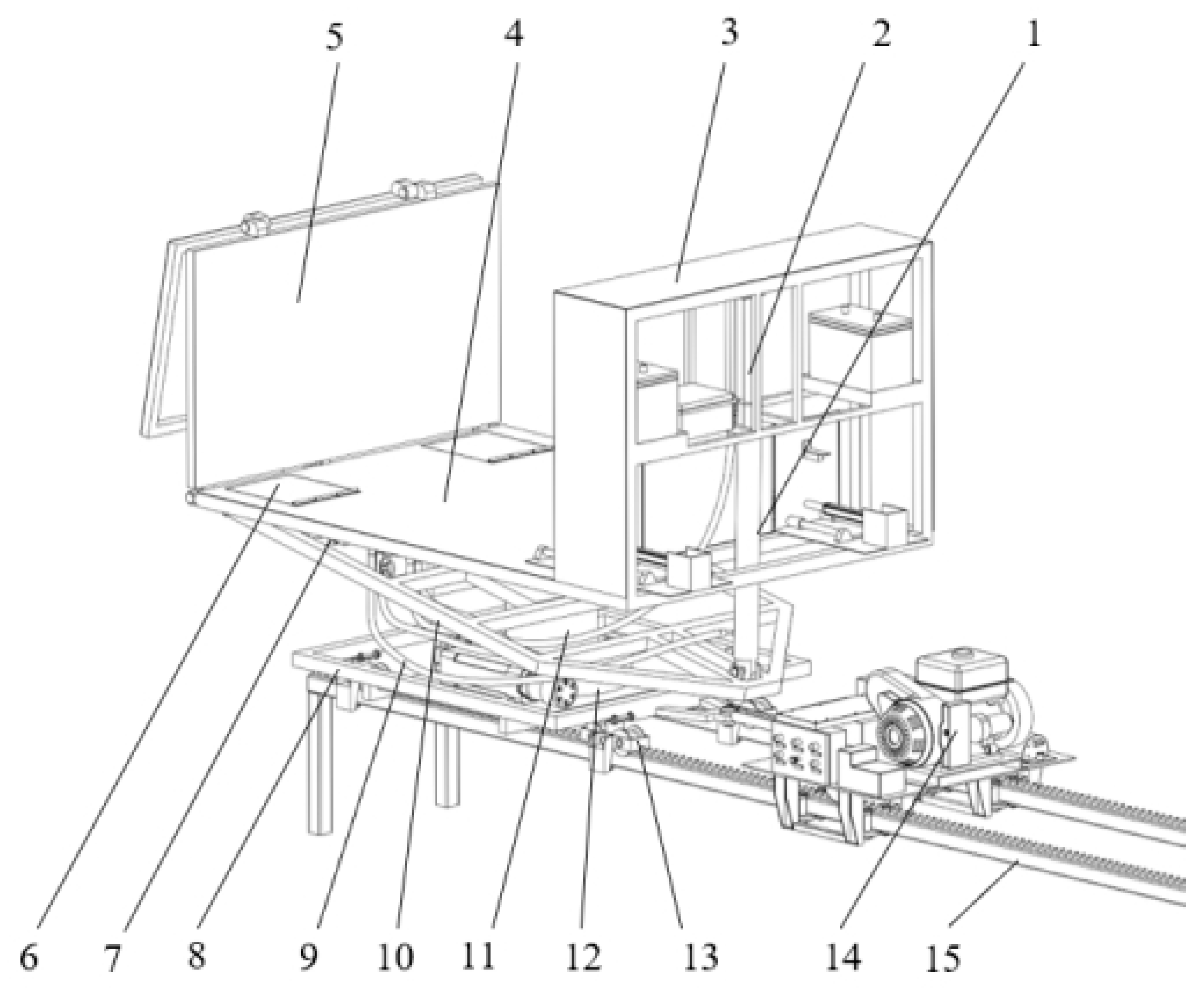
A rail-based agricultural machinery transport platform system consists of a rail system, a transport platform mechanism, a power drive system, and an attitude adjustment and control system. The rail system provides guidance and a load-bearing foundation, and the transport platform mechanism handles the transportation of agricultural machinery and loads. The power drive system enables the platform to move along the rails, and the attitude adjustment and control system uses an inertial measurement unit (IMU) sensor to detect the platform’s roll and pitch angles and drives hydraulic actuators to perform dynamic leveling. The overall system structure is shown in Figure 1.
Given the wide range of track gradients and the potential shifts in load distribution in hilly and mountainous rail transport environments, a platform may experience shifts in the center of mass, increasing the attitude fluctuations and overturning risk during operation. Therefore, in addition to meeting load-bearing and transport requirements, the platform’s structural design must address leveling capabilities and stability control needs. Table 1 lists the main structural and control parameters of the transport platform system. In this study, these parameters were used for the attitude modeling and stability control analysis of the platform.

2.1.2. Key Structural Design of a Transhipment Platform

A transport platform is equipped with key modules such as a quick-release fastening mechanism and an automatic rotating loading/unloading mechanism. Both mechanisms ensure efficient loading and unloading of agricultural machinery and load stability during transport. Therefore, these mechanisms affect not only the operational convenience but also the load distribution of the agricultural machinery on the platform; they also influence the platform’s center of gravity and operational stability.
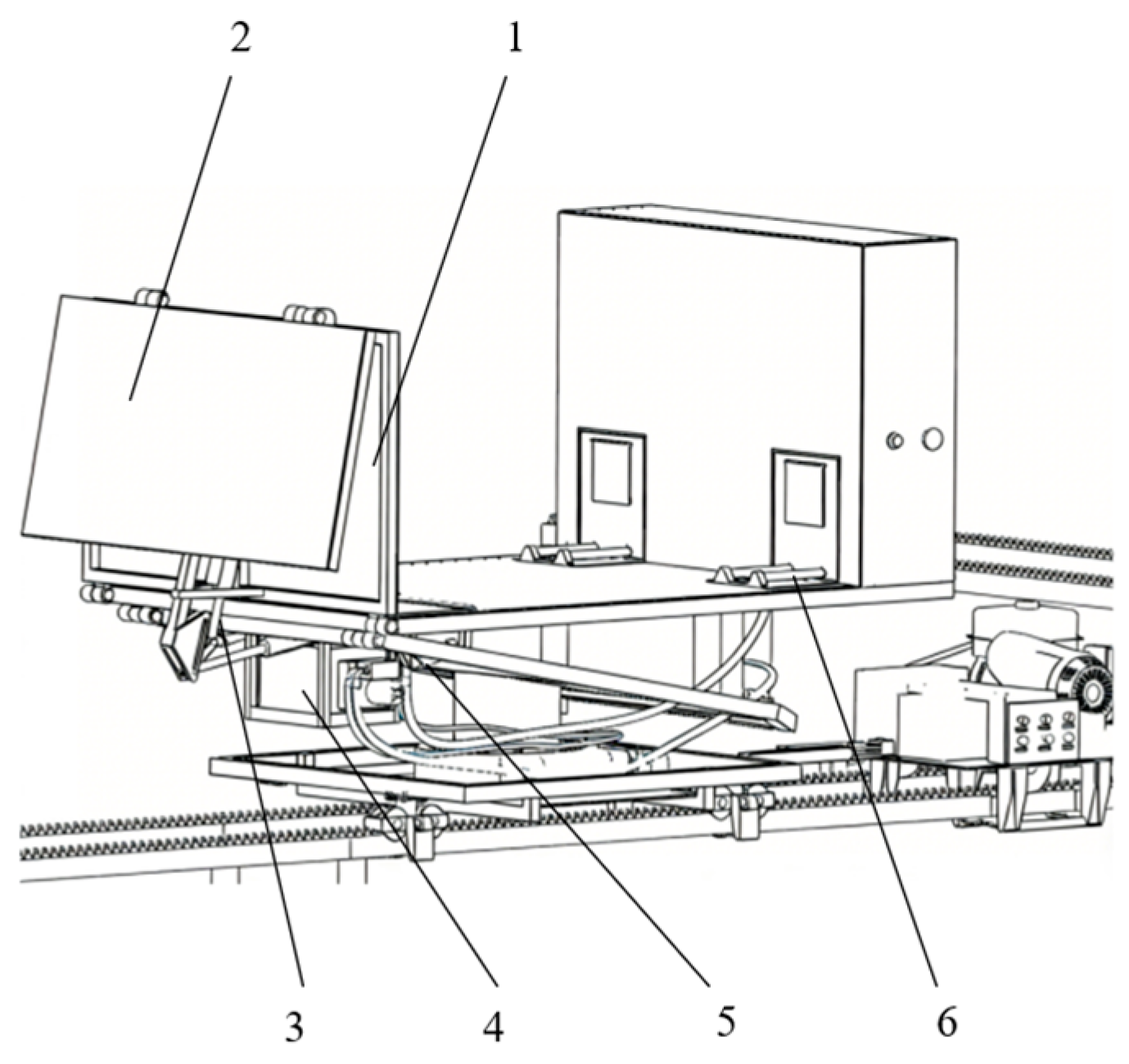
During transport, the rapid-locking mechanism suppresses the relative load displacement, and the automatic rotating mechanism optimizes the loading and unloading orientation. Both mechanisms affect the spatial distribution of agricultural machinery on the platform and alter the system’s center of gravity. In this study, the effects of both mechanisms on attitude disturbance and overturning risk were investigated from the perspective of system stability. The structural configuration of the key transport platform mechanisms is shown in Figure 2.

2.1.3. Principles of Platform Attitude Adjustment and Stabilization Control

In hilly and mountainous rail transport environments, changes in track gradient, load shifts, and operational vibrations cause the transport platform to experience roll and pitch disturbances during operation, indicating reduced platform stability; in severe cases, the risk of overturning is even higher [9,20,21,22,23,24,25]. In this study, an attitude adjustment and control module was introduced into the platform system to ensure real-time sensing, dynamic adjustment, and stable control of the platform’s attitude.
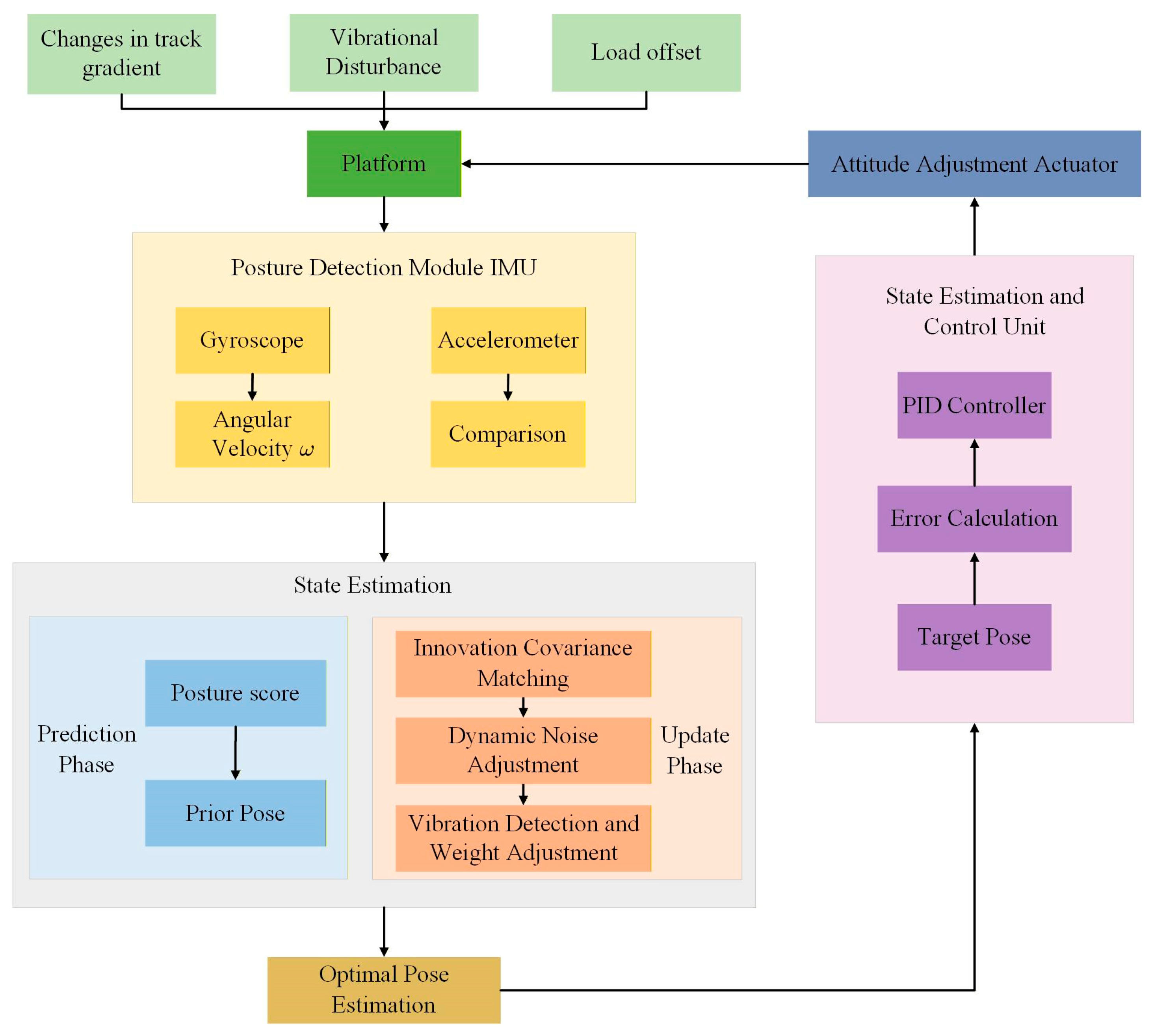
The attitude adjustment and control system of the platform primarily includes an attitude detection unit, a state estimation and control unit, and attitude adjustment actuators. The IMU sensor acquires real-time information about the platform’s roll and pitch angles. After the state of the system is estimated, attitude feedback is obtained, and the controller outputs leveling commands on the basis of the deviation between the target attitude and the current attitude. These commands drive the actuators to correct the platform’s attitude, thereby forming a closed-loop “attitude detection—state estimation—control decision—execution and adjustment” control chain. The principles of platform attitude adjustment and stability control are presented in Figure 3.
In addition to the influence of the track gradient, platform stability is affected by the load distribution and the position of the system’s center of mass. A shift in the center of mass caused by load displacement or changes in attitude alters the gravitational moment and increases the overturning risk.

2.2. Platform Attitude and State Estimation and Adaptive KF Control Methods

2.2.1. Problem Analysis of the Centre of Mass Displacement and the Attitude Adjustment of the Platform State

In hilly and mountainous rail transport environments, the distribution of the loaded mass of agricultural machinery on transport platforms is uneven. When the platform travels along the track, changes in track gradients, shifts in load positions, and disturbances in platform vibration cause the system’s overall center of mass to shift, ultimately affecting the platform’s attitude stability [6,7,8,20,21,22,23,24]. As the projection of the system’s center of mass gradually approaches the boundary of the track support, the risk of platform overturning increases considerably. In this study, the attitude stability control and the coupling relationship between the migration of the system’s center of mass and the platform’s attitude stability were analyzed comprehensively.
Owing to its structural design, the roll and pitch attitudes of a rail-based agricultural machinery transport platform can be dynamically adjusted using attitude control actuators to counteract the attitude disturbances caused by load displacement and changes in gradient. In this study, the impact of changes in load distribution on platform stability was analyzed by treating the transport platform and the agricultural machinery it carried as a rigid-body system. Let the system have n components, where the mass of the i -th component is given by m i , and its center of mass coordinates are given by x i , y i , z i . The coordinates of the system’s overall center of mass can then be expressed as follows:
x c = i = 1 n m i x i i = 1 n m i ,   y c = i = 1 n m i y i i = 1 n m i ,   z c = i = 1 n m i z i i = 1 n m i
where i = 1 n m i = M is the total mass of the system, and x c , y c , and z c are the coordinates of the system’s center of mass in the X, Y, and Z directions, respectively.
During transport on sloping terrain, when agricultural machinery on the platform experiences lateral displacement or when the gradient of the track changes, the movement of this platform can be represented by roll and pitch angles. Roll motion directly affects the platform’s lateral stability and the overturning risk. When the platform rolls, the system’s center of mass shifts laterally relative to the centerline of the track support. In this study, the lateral projected displacement is approximated as follows:
y r = z c s i n ϕ
Consider a slight change in the platform’s attitude. A small-angle approximation s i n ϕ ϕ may be used such that
y r z c ϕ
Let the distance between the left and right supports of the track be b . The platform is in a critical overturning state when the projection of the system’s center of mass reaches the support boundary [6,7,8]. From a geometric perspective, the critical roll angle of the platform can be expressed as follows:
ϕ c = a r c t a n ( b 2 z c )
where b is the track support spacing; z c is the height of the system’s center of mass; and ϕ c is the platform’s critical roll angle. The greater the height of the system’s center of mass is, the smaller the critical roll angle and the lower the rollover stability margin. Therefore, the platform is sensitive to variations in z c , especially under high-load or high-center-of-mass conditions [6,7,8].
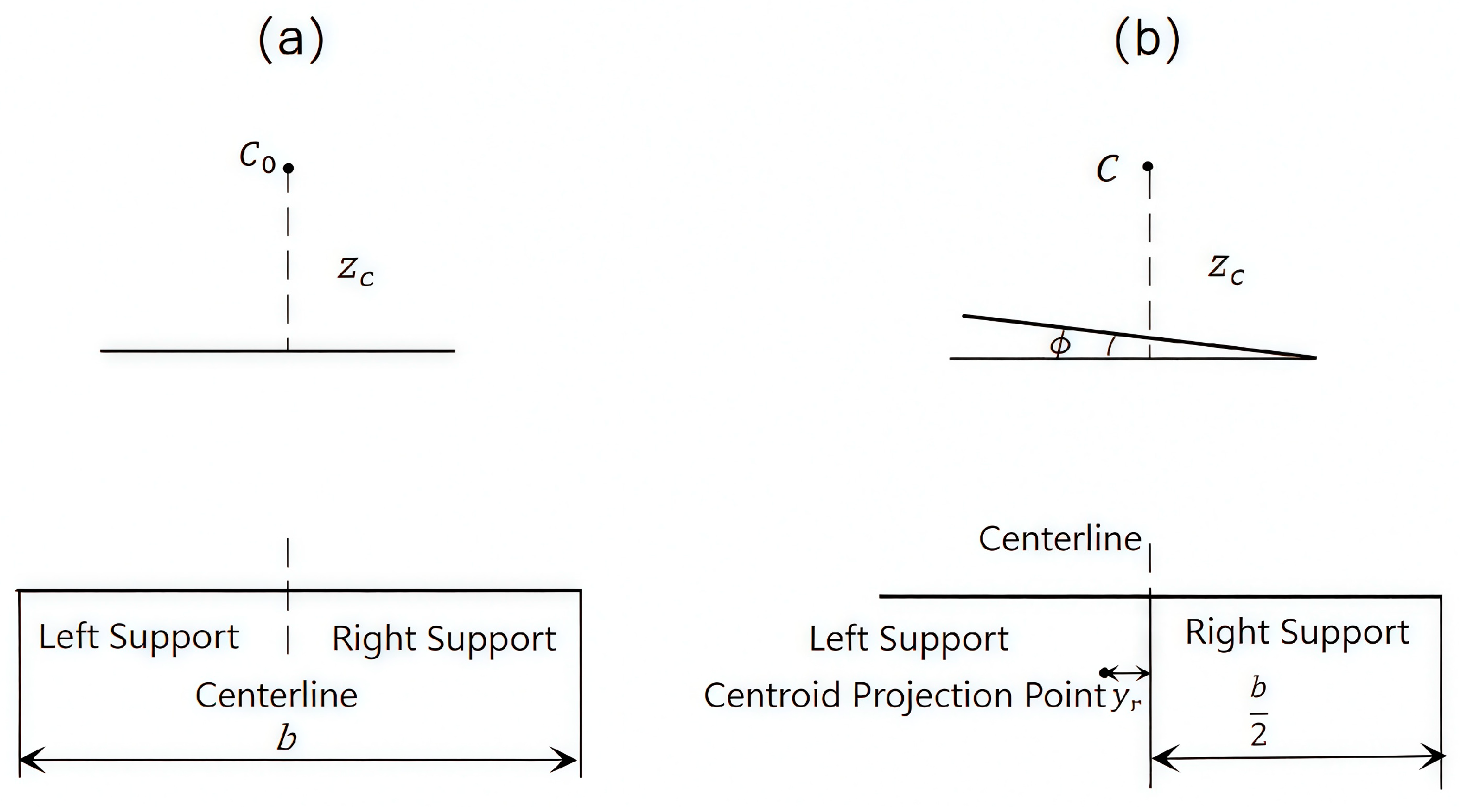
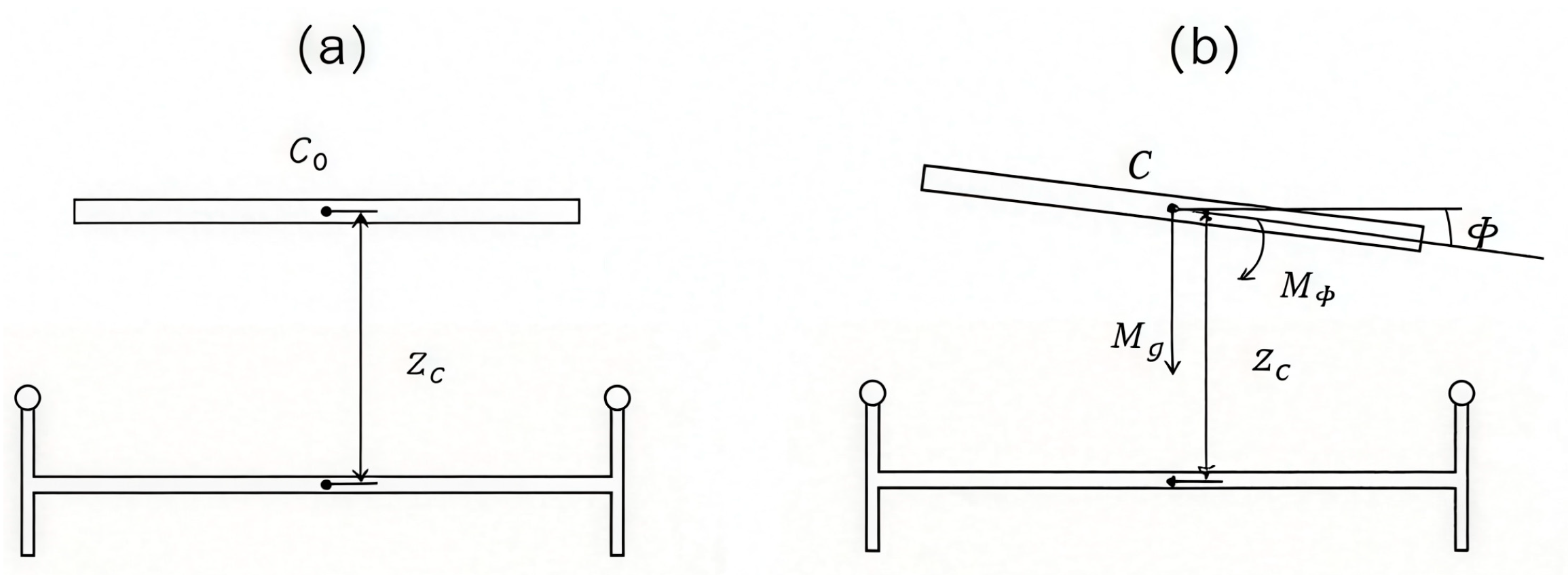
However, platform stability is affected not only by changes in the track gradient but also by the height of the system’s center of mass and the distribution of the load. In scenarios where the load displacement increases the lateral projection displacement, the platform’s resistance to overturning decreases considerably. In this study, a roll dynamics model was established to accurately reflect the platform’s attitude changes under complex disturbance conditions and to provide state inputs for subsequent controller design, allowing for efficient estimation of the attitude state. The relationship between the center-of-mass projection and the rollover boundary is illustrated in Figure 4.

2.2.2. Model Assumptions and Application Scope

This study provides a unified explanation of the assumptions and scope of application of the platform’s roll dynamics model, the attitude state-space model, and the equivalent treatment of actuators.
The following assumptions were considered to facilitate the establishment of the platform’s attitude state-space model, followed by attitude estimation and closed-loop control of the system. First, under normal low-speed transport and leveling conditions, the transport platform and the agricultural machinery it carries are regarded as a rigid-body system, because the load is constrained by the platform support and fastening structure. Second, because the attitude adjustment range of the leveling mechanism is limited, the small-angle approximation is adopted for the roll and pitch motions. Third, the roll and pitch attitude channels are considered decoupled for upper-level attitude estimation and control, while the unmodeled coupling effects are treated as external disturbances and system noise. Finally, hydraulic actuation is assumed to be equivalent to the control of torque inputs in the attitude leveling direction.
On the basis of the abovementioned assumptions, the model established in this study is applicable primarily to upper-level state estimation and stability control analysis of rail-based agricultural machinery transport platforms in hilly and mountainous terrain under normal transport and low-range attitude leveling conditions. The aim of this research is to provide a computable and analyzable theoretical foundation for subsequent attitude modeling, filtering estimation, and controller design. For large-angle disturbances, steep-slope operation close to the rollover boundary, severe load sliding, strong vibration, strongly coupled roll–pitch dynamics, or rapid nonlinear hydraulic actuator responses, the above assumptions may become invalid. Under these conditions, roll–pitch coupling cannot be ignored, and a higher-fidelity nonlinear coupled model would be required for more accurate dynamic analysis.
The proposed model was designed to provide a computable and analyzable simplified theoretical foundation for attitude state estimation, closed-loop controller design, and stability evaluation rather than to perform a complete, high-fidelity reconstruction of all underlying physical processes of the platform.

2.2.3. Platform Roll Dynamics Model

In hilly and mountainous terrain, variations in the track gradient and uneven distribution of agricultural machinery loads cause attitude disturbances in the transport platform during operation, and roll motion is the primary factor affecting platform stability and overturning risk [4,5,6,7,8]. In this study, a roll dynamics model was established to theoretically elucidate the attitude state estimation and design of stability control algorithms for the platform.
Let the total mass of the transport platform and its payload system be M , the moment of inertia of the system about the roll axis be J ϕ , the vertical distance from the system’s center of mass to the track support surface be z c , and the platform’s roll angle be ϕ . When the platform is affected by changes in the track gradient or load displacement, attitude deviation occurs in the roll direction. The platform is subjected to three types of torque in the roll direction: roll torque generated by gravity, control torque generated by the attitude control mechanism, and external disturbance torque. In line with the principles of rigid-body rotational dynamics, the motion of the platform about the roll axis should satisfy the following:
J ϕ ϕ ¨ = M ϕ
where M ϕ is the resultant torque acting on the platform about the roll axis; J ϕ is the moment of inertia of the platform about the roll axis; and ϕ ¨ is the angular acceleration of the platform’s roll angle.
In the roll direction, the net system torque mainly includes
M ϕ = M g + M u + M d
where M g is the roll torque caused by gravity; M u is the control torque generated by the attitude control mechanism; and M d is the equivalent disturbance torque caused by track irregularities, slope variations, mechanical vibrations, and external impacts. In this study, these complex field disturbances are represented as equivalent disturbance inputs and system noise for upper-level attitude estimation and control.
When the platform rolls, the system’s center of mass shifts relative to the centerline of the support, creating a rolling moment under the influence of gravity. This gravitational moment can be expressed as follows:
M g = M g z c s i n ϕ
where g is the acceleration caused by gravity, and z c is the height of the system’s center of mass.
Substituting the torque relationships into the dynamic equations yields the following roll dynamic equation:
J ϕ ϕ ¨ = M g z c s i n ϕ + M u + M d
Given that the attitude control system of a platform typically operates within a small angle range, a small-angle approximation s i n ϕ ϕ may be applied, allowing Equation (8) to be linearized as follows:
J ϕ ϕ ¨ = M g z c ϕ + M u + M d
ϕ ¨ = M g z c ϕ J ϕ + M u J ϕ + M d J ϕ
Therefore, the height of the system’s center of mass directly influences the magnitude of the gravitational roll moment. As height z c increases, the gravitational term M g z c ϕ increases accordingly, making the platform highly susceptible to roll responses under external disturbances, ultimately reducing its stability. During attitude control, actuators can be utilized not only to provide corrective torques for suppressing roll motion but also to employ state estimation methods for obtaining real-time information about attitude changes in the platform. This step enhances stability control under complex disturbance conditions.
Let the equivalent control commands for the hydraulic actuator in the roll and pitch directions be δ ϕ , k and δ θ , k , respectively. The equivalent leveling torque can be expressed as follows:
M u , ϕ , k = K ϕ δ ϕ , k
M u , θ , k = K θ δ θ , k
where K ϕ and K θ are the equivalent torque conversion coefficients for the hydraulic actuator in the roll and pitch directions, respectively. Both variables represent the combined effects of factors such as the hydraulic actuator’s output capacity, mounting position, and mechanical transmission relationships. δ ϕ , k and δ θ , k , denoting the actuation of the mechanical lever arms of the platform, represent the equivalent command outputs of the controller.
Further considering the output capacity constraints of the actuator, the equivalent balancing torque should satisfy the following:
M u , ϕ , k M ϕ , m a x
M u , θ , k M θ , m a x
where M ϕ , m a x and M θ , m a x are the maximum available leveling torques in the roll and pitch directions, respectively. The magnitudes denoted by these variables are determined jointly by the maximum load capacity of the hydraulic actuators and the mechanical lever arms.
In contrast to the local response of the hydraulic actuators, the attitude adjustment process of the platform evolves much more slowly. In this study, higher-order factors, such as hydraulic valve dynamics, fluid compressibility, and frictional hysteresis, were ignored in the control model, and the actuators were simplified to static equivalent-torque elements for upper-level attitude control under low-speed and small-range leveling conditions. This simplification cannot fully describe rapid hydraulic transients or high-frequency actuation responses, which will be further considered in future work. This simplification indicates that the control inputs in the state-space model can be represented by equivalent leveling torques in the roll and pitch directions.
By further defining the state variables as x 1 = ϕ ,   x 2 = ϕ ˙ , the roll direction as the equivalent control input u ϕ = M u , ϕ , and the disturbance input w ϕ = M d , ϕ , the roll dynamics equation can be expressed in continuous-time state-space form as follows:
x 1 ˙ = x 2 x 2 ˙ = M g z c x 1 J ϕ + u J ϕ + w J ϕ
The modeling framework provides the dynamical foundation for the subsequent development of the attitude state-space model and the design of the adaptive Kalman filter (AKF) algorithm for the platform. The corresponding roll force analysis of the platform is shown in Figure 5.

2.2.4. Development of the Platform Attitude State-Space Model

A discrete state-space model was established on the basis of the aforementioned roll dynamics model to estimate the platform’s attitude state [15,16,17,18,19]. The platform’s attitude state is defined as a state vector comprising the roll angle, roll angular velocity, pitch angle, and pitch angular velocity:
x k = [ ϕ k ϕ ˙ k θ k θ ˙ k ]
where x k is the system state vector at a discrete time step; ϕ k and θ k are the system state vectors at a discrete time step; θ ˙ k represents the platform’s roll angle and pitch angle; and ϕ ˙ k represents the roll angular velocity and pitch angular velocity.
On the basis of the roll dynamics equations presented in Section 3.2 and by employing a similar modeling approach for pitch, the platform’s attitude dynamics can be expressed as a discrete state transition equation as follows:
x k = A x k 1 + B u k 1 + ω k 1
where x k is the system state at time; A is the state transition matrix; B is the control input matrix; u k 1 is the control input vector; and ω k 1 is the system noise vector. These variables represent the modeling errors and random disturbances caused by track irregularities, mechanical vibrations, and external disturbances.
Given a sampling period of T s , the attitude state transition matrix of the platform can be approximated as follows:
A = 1 T s 0 0 a ϕ T s 1 0 0 0 0 1 T s 0 0 a θ T s 1
a ϕ = M g z c J ϕ ,   a θ = M g l c J θ
where a ϕ and a θ are the equivalent gravitational coefficients in the roll and pitch directions, respectively; J ϕ and J θ are the moments of inertia of the platform about the roll and pitch axes, respectively; z c is the height of the system’s center of mass relative to the roll support surface; and l c is the equivalent distance of the system’s center of mass relative to the pitch axis.
The platform leveling mechanism applies control forces in the roll and pitch directions. Thus, the control input vector can be defined as follows:
u k = M u , ϕ , k M u , θ , k
where M u , ϕ , k and M u , θ , k are the equivalent control torques generated by the hydraulic leveling actuators in the roll and pitch directions, respectively. The hydraulic actuators are simplified to static equivalent-torque elements in accordance with upper-level attitude control laws.
The corresponding control input matrix can be written as follows:
B = 0 0 b ϕ T s 0 0 0 0 b θ T s
b ϕ = 1 J ϕ , b θ = 1 J θ
According to Equation (22), the roll control input acts solely on the roll angular velocity channel, whereas the pitch control input acts solely on the pitch angular velocity channel. Under the current simplified model, these two metrics were treated as decoupled channels.
The attitude detection unit of the platform uses an IMU sensor to acquire attitude-related information. The raw output of the IMU includes angular velocity and acceleration signals. After the front-end attitude calculation, the IMU sensor yields measured values for the roll angle and pitch angle. As this study focused mainly on state estimation and closed-loop leveling control of the platform’s attitude angles, only the roll angle and pitch angle were directly observed in the upper-level AKF model. The angular velocity information was primarily used for attitude prior updating and the calculation of intermediate control variables. The attitude observation equation of the platform can be expressed as follows:
z k = H x k + v k
where H is the observation matrix; z k is the observation vector; and v k is the observation noise vector. In accordance with measurements applicable to the IMU sensor, the observation vector can be expressed as follows:
z k = [ ϕ m , k θ m , k ]
where ϕ m , k and θ m , k are the roll angle and pitch angle measured by the IMU sensor, respectively. The corresponding observation matrix is given by
H = 1 0 0 0 0 0 1 0
The system noise w k primarily stems from vibration interference caused by the platform’s movement along the track, track irregularities and modeling errors, whereas the observation noise v k primarily stems from measurement errors in the IMU sensors.

2.2.5. Traditional KF-Based Attitude Estimation Methods

On the basis of the state-space model described above, a traditional KF method was employed for baseline attitude estimation. The basic principle of estimation involves predicting the current state of the system model and correcting predictions using sensor observations, from which a recursive estimate of the platform’s attitude state is obtained [10,11,12,13]. The prediction stage can be expressed as follows:
x ^ k | k 1 = A x ^ k 1 | k 1 + B u k 1
P k | k 1 = A P k 1 | k 1 A T + Q
where x ^ k | k 1 is the prior state estimate at time k ; x ^ k 1 | k 1 is the posterior state estimate at time k 1 ; P k | k 1 is the prior error covariance matrix; P k 1 | k 1 is the posterior error covariance matrix at the previous time step; and Q is the system noise covariance matrix.
Let the observation be completed at time k . The Kalman gain and state update processes can then be expressed as follows:
K k = P k | k 1 H T ( H P k | k 1 H T + R ) 1
x ^ k = x ^ k | k 1 + K k ( z k H x ^ k | k 1 )
e k = z k H x ^ k | k 1
P k = ( I K k H ) P k | k 1
where K k is the Kalman gain matrix at time k ; R is the observation noise covariance matrix; e k is the observation residual vector; and I is the identity matrix.

2.2.6. Improvements to the AKF Algorithm

Given the distinctly time-varying nature of system noise and observation noise in hilly and mountainous rail transport environments, this study develops an improved AKF algorithm based on the traditional KF framework. The novelty of the proposed method lies not in establishing a new general nonlinear filtering theory, but in constructing a platform-oriented adaptive covariance correction strategy for rail-based agricultural transport under slope variation, load migration, and vibration disturbance. Different from the conventional KF with fixed noise covariance, the proposed method uses innovation residual statistics to update both the observation noise covariance and the system noise covariance online. In addition, a covariance saturation mechanism is introduced to suppress abnormal covariance fluctuations caused by transient disturbances. Compared with EKF and UKF, the proposed method is more suitable for the small-angle leveling model used in this study because it avoids additional Jacobian calculation or sigma-point propagation while maintaining real-time estimation robustness.
At time k , state prediction is initially performed using the system state equations to obtain the prior state estimate and the prior error covariance matrix.
x ^ k | k 1 = A x ^ k 1 | k 1 + B u k 1
P k | k 1 = A P k 1 | k 1 A T + Q k 1
where x ^ k | k 1 is the prior state estimate at time; P k | k 1 is the prior error covariance matrix; A is the state transition matrix; B is the control input matrix; and Q k 1 is the system noise covariance matrix updated at the previous time step.
After the z k measurements are obtained by the IMU, the residuals are further calculated as follows:
e k = z k H x ^ k | k 1
where H is the observation matrix, and e k is the deviation between the current observation data and the model prediction. Given that the statistical properties of the observation residuals can demonstrate changes in the current level of observation noise to a certain extent, an exponential weighting method is employed to adaptively update the observation noise covariance matrix.
R k = 1 α R k 1 + α ( e k e k T )
where α ( 0,1 ) is the update factor for the covariance of the observation noise. A large α increases the filter’s response speed to changes in noise but may introduce significant fluctuations, whereas a small α improves the filtering stability.
Furthermore, as the observation residuals may experience transient spikes under complex disturbance conditions, directly incorporating R ~ k into the filtering update might cause severe fluctuations in the covariance. A clipping process can be applied to the observation noise covariance to improve the filtering stability as follows:
R k = s a t ( R ~ k , R m i n , R m a x )
where R m i n and R m a x are the lower and upper bounds of the observation noise covariance, respectively. s a t ( R ~ k , R m i n , R m a x ) represents the clipping function, which is used to ensure that R k remains within a reasonable range at all times.
After the observation noise covariance matrix R k is updated, the Kalman gain is calculated for the current time step.
K k = P k | k 1 H T ( H P k | k 1 H T + R k ) 1
System noise manifests primarily as a model prediction error. Thus, the Kalman gain at the current time step and the observation residuals are employed to adaptively adjust the system noise covariance matrix.
Q k = 1 β Q k 1 + β K k e k e k T K k T
where β ( 0,1 ) is the system noise covariance, which is updated by the Q k factor. However, the updated value does not directly contribute to the calculation of the Kalman gain at the current time step but is instead used in the recursive calculation of the prediction error covariance matrix at the next sampling time step. On this basis, the statistical characteristics of system noise can be gradually adjusted online.
The state prediction results are subsequently corrected using the Kalman gain at the current time step. This step yields the posterior state estimate and the posterior error covariance matrix as follows:
x ^ k | k = x ^ k | k 1 + K k e k
P k | k = ( I K k H ) P k | k 1
Let x ^ k | k be the posterior state estimate at time k ; let P k | k be the posterior error covariance matrix; and let I be the identity matrix. The prior error covariance matrix at the next time step can be written as follows:
P k + 1 | k = A P k | k A T + Q k
With regard to parameter initialization, the traditional KF method employs a fixed-noise covariance matrix. In the improved AKF, the initial system noise covariance is set as follows:
Q 0 = 0.02 I
R 0 = 0.8 I
where Q 0 represents improvements in the initial system noise covariance of the AKF, and R 0 represents the initial observation noise covariance. The improved AKF can subsequently perform online adjustments to the noise statistical properties in response to changes in the residuals. This step ultimately enhances the accuracy and robustness of attitude estimation under complex disturbance conditions.
The improved AKF method dynamically tracks the statistical characteristics of observation noise and system noise through a process involving “observation residual-driven online updating R k —calculation of current gains—adaptive correction of system noise covariance Q k —recursive prediction for the next time step” [15,16,17,18,19]. Compared with the traditional fixed-parameter KF method, the improved AKF method can more effectively mitigate the impact of noise uncertainty on attitude estimation accuracy under complex operating conditions, such as changes in the track gradient and increased vibration and load disturbances. Consequently, the improved AKF method can enhance the stability and robustness of the platform’s roll and pitch angle estimates.
Since the state vector contains only four states and the observation vector contains two attitude angles, the improved AKF only involves small-scale matrix operations at each sampling step and is therefore suitable for real-time embedded implementation.
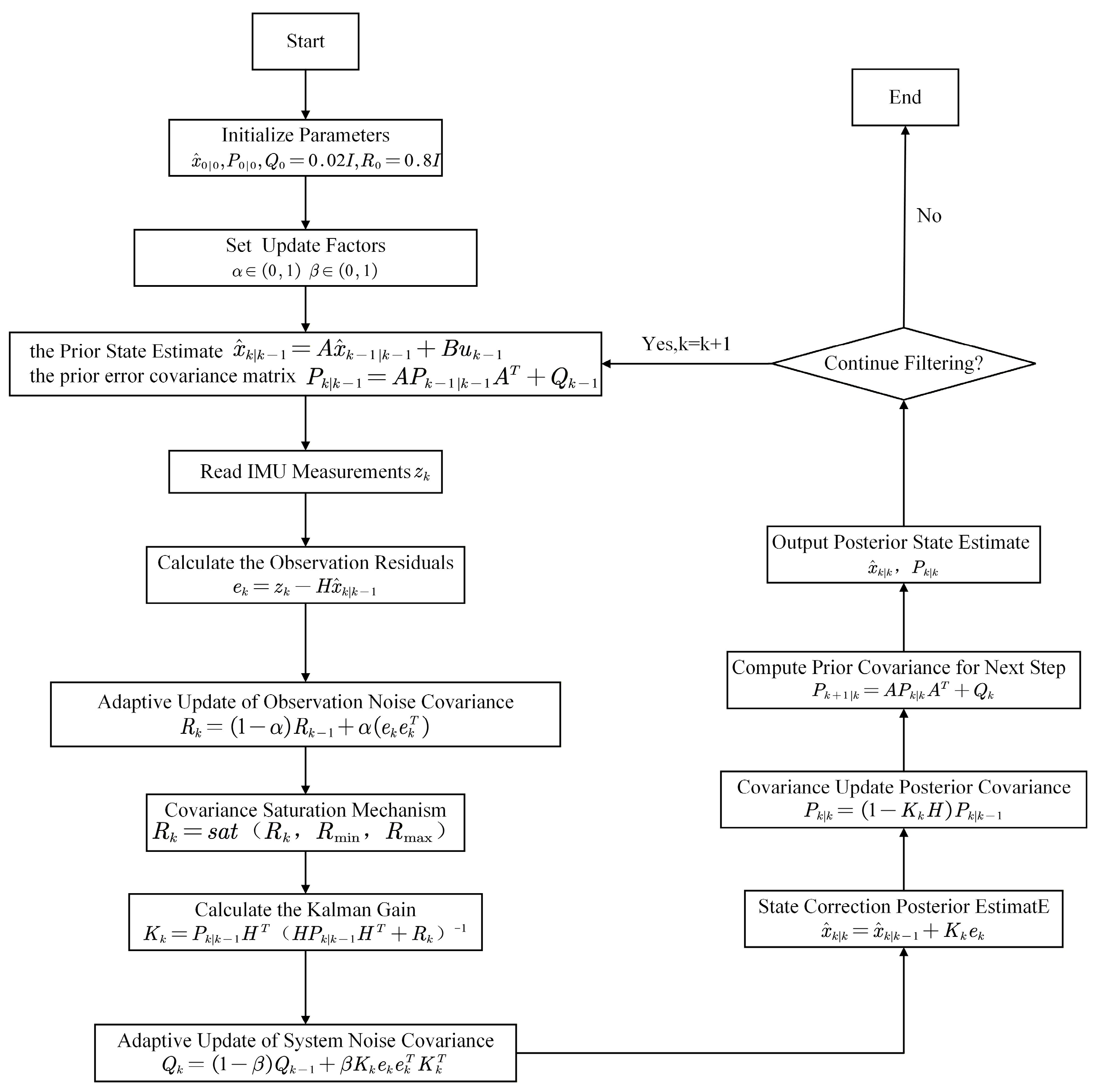
The implementation steps of the improved AKF algorithm are shown in Figure 6.

2.2.7. PID-Based Closed-Loop Attitude Control Strategy

After the platform’s roll and pitch angles are estimated in real time, a closed-loop attitude control strategy is employed to achieve automatic leveling and stability control under complex terrain disturbance conditions. PID controllers have simple structures, are easy to implement, and offer good dynamic performance [25]. Thus, a PID control method was employed in this study to construct the platform’s closed-loop attitude control system, where the attitude estimates derived from the modified AKF were used as the control feedback.
The PID controller was selected mainly considering the engineering implementation requirements of the hydraulic leveling system and the research focus of this study. The main objective of this work was to evaluate the influence of the improved AKF on attitude feedback quality and leveling performance under the same control framework. Compared with model predictive control (MPC), PID control does not require a highly accurate prediction model or online constrained optimization, which reduces the computational burden for real-time implementation. Compared with sliding mode control (SMC), PID control can avoid potential high-frequency chattering that may adversely affect hydraulic actuators.
Let the target attitudes for the platform’s roll and pitch angles be ϕ d and θ d , respectively, and let the corresponding real-time attitude estimates obtained from the modified AKF be ϕ ^ and θ ^ . The control errors in the roll and pitch directions are defined as follows:
e ϕ t = ϕ d ϕ ^ ( t )
e θ t = θ d θ ^ ( t )
The PID controllers used in this study were designed separately for the roll and pitch axes of the platform. The control laws of these controllers can be expressed as follows:
u ϕ t = K p ϕ e ϕ t + K i ϕ 0 t e ϕ ( τ ) d τ + K d ϕ d e ϕ ( t ) d t
u θ t = K p θ e θ t + K i θ 0 t e θ ( τ ) d τ + K d θ d e θ ( t ) d t
where u ϕ t and u θ t are the control inputs for the roll and pitch directions, respectively; K p is the proportional gain; K i is the integral gain; and K d is the derivative gain.
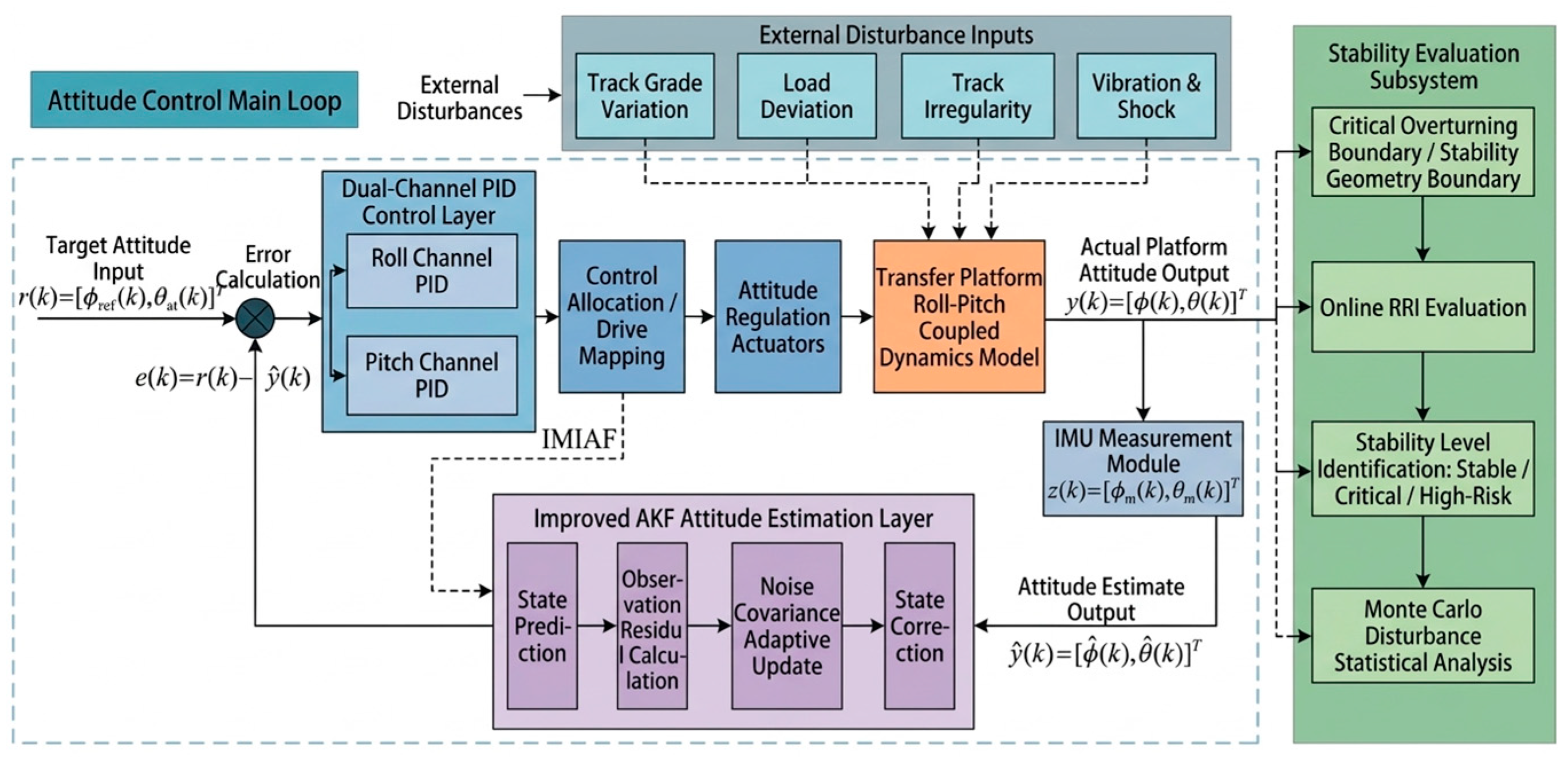
The logical relationships among attitude perception, state estimation, feedback control, and stability evaluation [22,23,24] of the improved AKF–PID hierarchical attitude stabilization control are shown in Figure 7. This architecture includes a target attitude input layer, a state perception and estimation layer, a closed-loop control decision layer, an actuator and a controlled object layer, and a stability evaluation layer. These parts form an integrated stability control framework involving “attitude perception—state estimation—closed-loop control—risk evaluation.”
Compared with the direct use of raw sensor measurements for feedback control, the closed-loop control method based on the improved AKF can better reduce the impact of measurement noise on the control input while avoiding control oscillation caused by amplified high-frequency noise. This design guarantees dynamic response performance and platform stability during the attitude adjustment process.

3. Results and Discussion

3.1. Simulation Platform and Parameter Settings

Platform attitude control suitable for hilly and mountainous agricultural machinery transport was simulated in MATLAB. The aim was to verify the effectiveness of the proposed platform’s attitude state estimation and stability control methods. The simulation model included the following: a platform attitude dynamics module, an IMU observation module, a traditional KF module and an improved AKF attitude estimation module, and a PID closed-loop control module. The initial attitude, target attitude, and random slope disturbance conditions of the platform were configured to align with the platform’s structural parameters and mountainous transport conditions. The simulation parameters are shown in Table 2.
The optimized AKF parameters and PID controller settings are shown in Table 3.
The modified AKF employs a noise-adaptive adjustment strategy, which includes “weighted updating of observation residuals, covariance capping, and residual energy smoothing,” whereas the traditional KF uses a fixed-noise covariance setting. The AKF parameters listed in Table 3 were determined through preliminary simulation tuning under stochastic gradient disturbance conditions. The coefficient α = 0.02 was selected to smooth the update of the observation noise covariance and avoid excessive fluctuations caused by transient vibration noise, whereas β = 0.15 was selected to improve the response of the system noise covariance to slope variation and load disturbance while maintaining filtering stability, while Q 0 and R 0 were initialized according to the expected model uncertainty and IMU measurement noise level.

3.2. Comparative Performances of Different Pose Estimation Algorithms

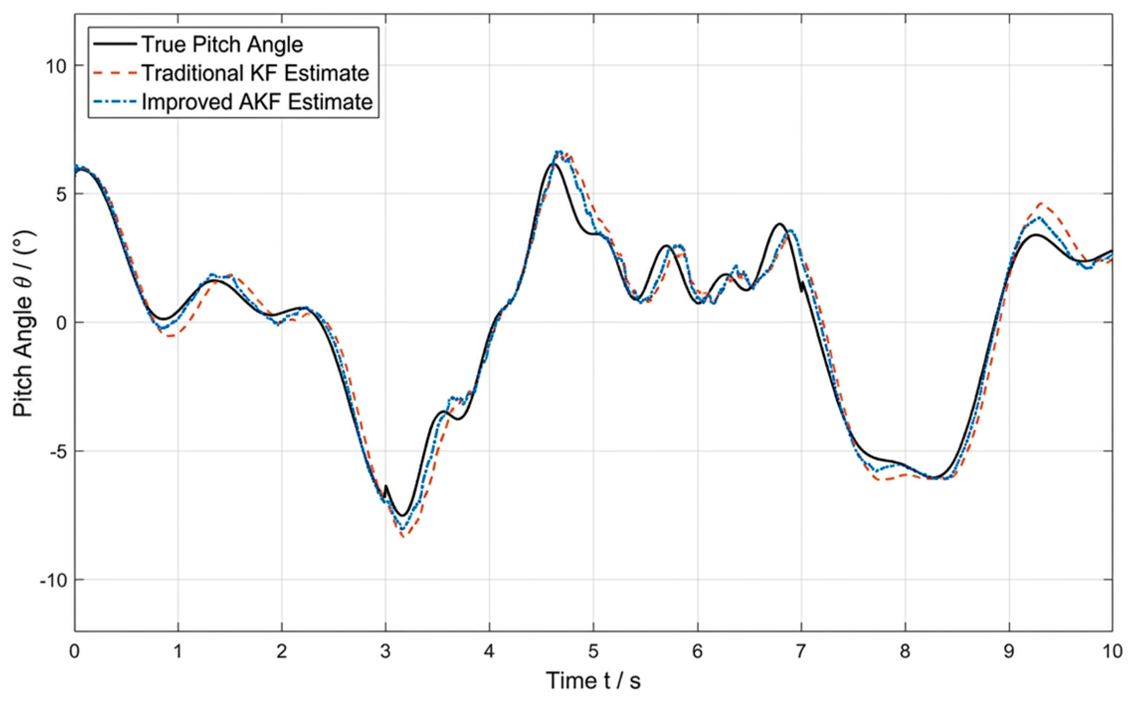
The performance of the improved AKF in terms of estimating platform attitude under complex disturbance conditions was verified. In particular, simulations were conducted to compare estimations of the platform’s roll and pitch angles using the traditional KF and the improved AKF [15,16,17,18,19]. The estimation curves and statistical error results were analyzed using the parameter settings identified for the attitude estimation algorithms (Table 3).
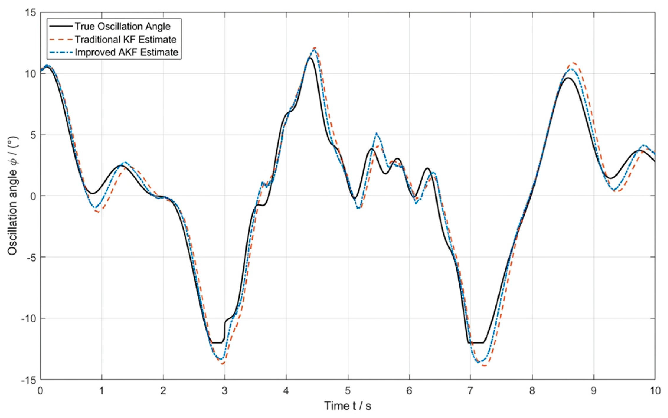
The roll and pitch angle estimation results of the traditional KF and the improved AKF under stochastic disturbance conditions are shown in Figure 8 and Figure 9, respectively. The statistical results of the estimation errors are presented in Table 4.
As shown in Table 4, the estimation errors for the roll angle and the pitch angle of the improved AKF are smaller than those of the traditional KF, indicating higher estimation accuracy for the proposed method.

3.3. Analysis of the Platform’s Attitude Control Performance

The platform’s attitude estimate was adopted as the feedback input for the control system. The PID controller was subsequently used to drive the attitude control actuators to achieve automatic leveling of the platform. In the simulation, the initial attitude of the platform was set to a roll angle of 6° and a pitch angle of 5°, whereas the target attitude was set to ϕ d = 0 ° , θ d = 0 ° .
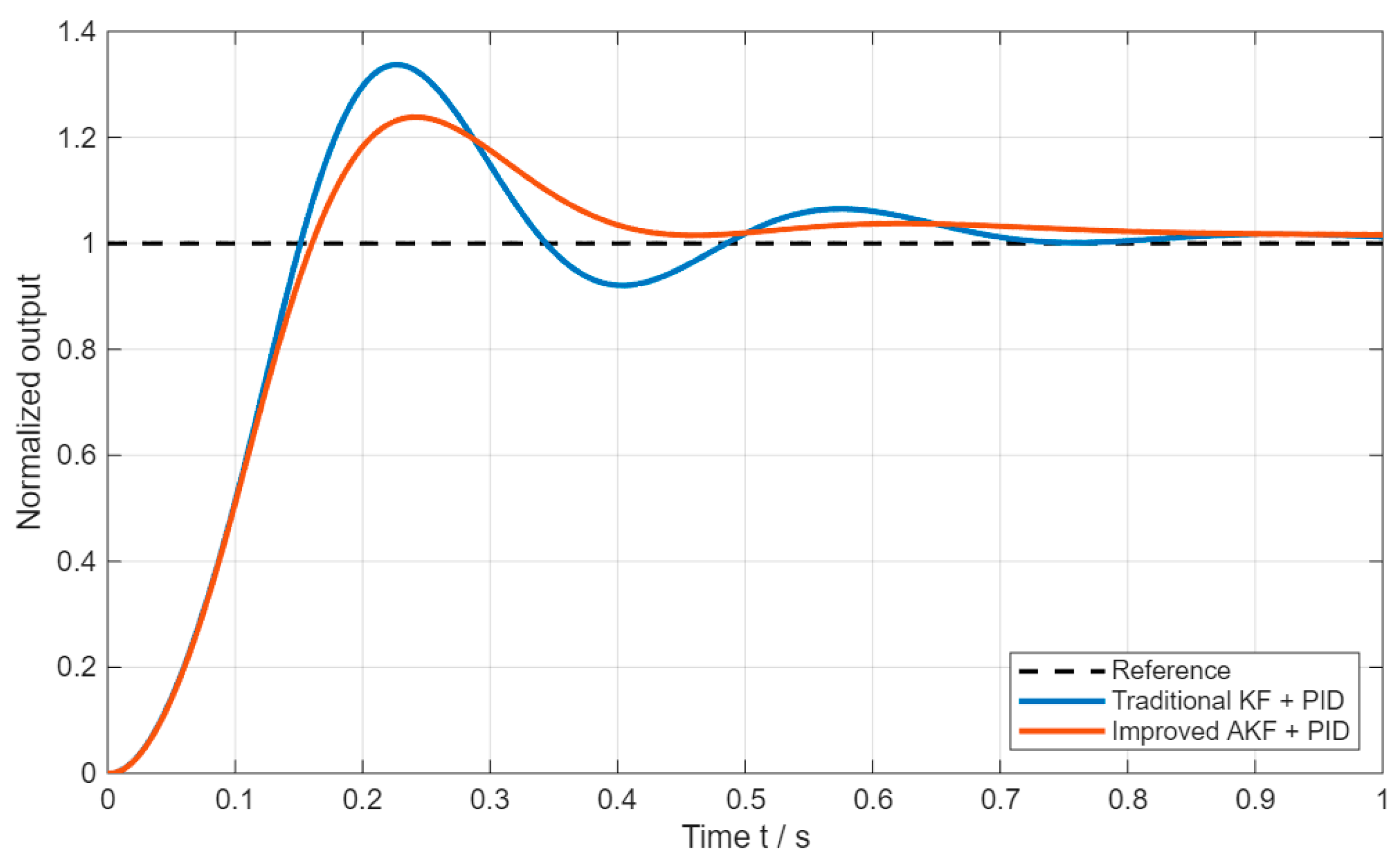
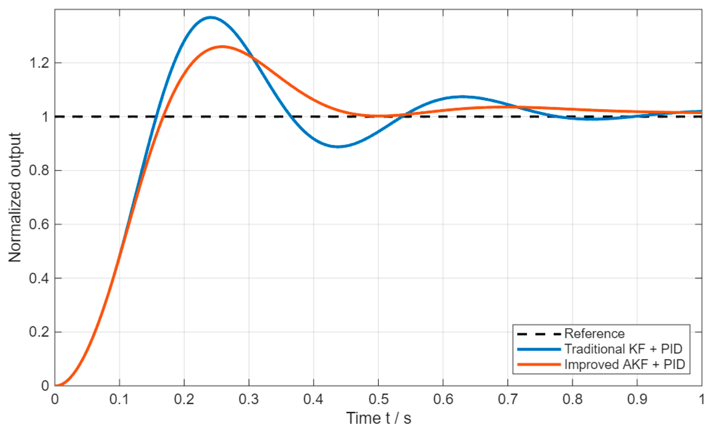
The control response curves for the platform’s roll angle and pitch angle are shown in Figure 10 and Figure 11, respectively. The simulation results indicate that under PID closed-loop control, the roll angle and pitch angle of the platform decay rapidly and then gradually converge to a position close to the target attitude. Comparatively, when the improved AKF is used as the attitude feedback, the control curves are smoother, the system response is faster, and the overshoot is reduced. The trends demonstrate that the improved attitude estimation method helps enhance the closed-loop control performance.
The settling time, maximum overshoot, and steady-state error were selected as the evaluation criteria in the quantitative analysis of control performance. The statistical results of the control performance for the two methods are presented in Table 5.
The settling times of the improved AKF+PID method in the roll and pitch channels were 0.383 s and 0.411 s, respectively, with corresponding maximum overshoots of 1.43° and 1.30°. These values are lower than those of the conventional KF+PID method (0.625 and 0.693 s; 2.02° and 1.84°), indicating the superior dynamic response performance of the improved AKF+PID method.
Although the improved AKF+PID method does not significantly reduce the steady-state error with respect to the traditional approach, the values of both methods remain within a narrow range. This difference can be explained by the steady-state accuracy of a closed-loop system relying primarily on the ability of the controller’s integral term to eliminate static error. The core contribution of the improved AKF lies in suppressing control chattering, which is caused by high-frequency measurement noise, and providing a smooth attitude feedback signal. These features help to improve the system’s dynamic response speed and anti-oscillation performance.
In summary, the advantages of the improved AKF+PID method are reflected primarily in the dynamic response speed, anti-oscillation capability, and disturbance suppression performance of the platform. With respect to the steady-state error, both methods remain within a small range, and the improved method does not demonstrate a reduction of an order of magnitude. Nevertheless, the proposed method is highly suitable for hilly and mountainous rail transport conditions where high standards of dynamic control quality and operational safety are expected.

3.4. Assessment of the Capsizing Risk Index

In terms of further evaluating the operational safety of the rail-mounted agricultural machinery transport platform under complex terrain conditions, changes in attitude angles alone are insufficient to fully reflect system stability. Therefore, building upon the attitude control simulation analysis, the rollover risk index (RRI) was introduced to quantitatively assess the platform’s stability [6,7,8].
According to the stability analysis results presented above, when the platform’s roll angle gradually approaches the critical roll angle, the projection of the system center of mass approaches the support boundary, and the rollover risk increases. To describe this stability margin quantitatively, the rollover risk index (RRI) was defined as the ratio between the real-time roll angle and the critical roll angle:
R R I = ϕ ϕ c
where ϕ is the platform’s real-time roll angle, and ϕ c is the critical roll angle determined by the platform geometry and the height of the system center of mass. The RRI physically represents how close the current roll attitude is to the theoretical rollover boundary. Compared with force-based stability metrics such as the load transfer ratio, the RRI is simpler and can be calculated from the estimated roll angle and geometric parameters, making it suitable for real-time risk evaluation.
According to the RRI value, the platform stability condition can be classified into stable, critical, and high-risk states, as shown in Table 6.

3.5. Monte Carlo Simulation Analysis of Random Gradient Perturbations

In real-world agricultural transport environments characterized by hilly and mountainous terrain, track laying is subject to complex topography, and the platform is continuously affected by factors such as random changes in gradient and track irregularities during operation. Thus, the stability of the proposed control method needs to be assessed under similar complex disturbance conditions. In this study, a Monte Carlo simulation was employed to statistically analyze the platform’s attitude control system.
During the simulation, track gradient disturbances were treated as random variables, and the variation range was set between 10° and 30°. With respect to simulation generation, the random gradient disturbances were assumed to follow a truncated normal distribution as follows:
γ ~ N ( μ , σ 2 ) ,   γ [ 10 ° , 30 ° ]
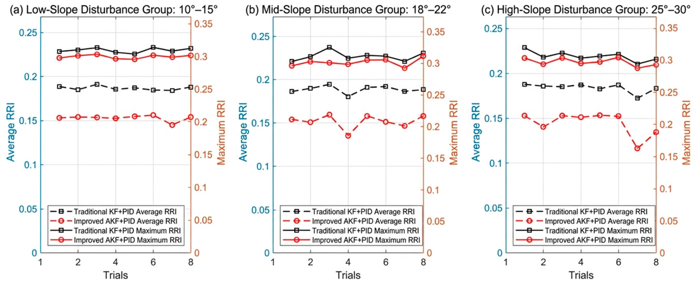
where N ( μ , σ 2 ) denotes a normal distribution with mean μ and variance σ 2 ; μ = 20 ° , σ = 5 ° , and the disturbance angle γ is truncated within the range of 10 30 ° . Different gradient disturbance scenarios, totaling 100 sets, were generated randomly under these conditions. Multiple simulation runs were performed for the conventional KF+PID and the improved AKF+PID control methods, and changes in the system’s RRI were recorded. The statistical results of the Monte Carlo simulations are presented in Table 7.
The average RRI of the improved AKF+PID method was 0.1506, and the maximum RRI was 0.3119, both of which were lower than the 0.1861 and 0.3255 recorded for the conventional KF+PID method. As shown in Figure 12, under different levels of slope disturbance, the RRI of the improved AKF+PID method is lower than that of the traditional method. Thus, the improved AKF+PID method can better reduce the operational risk of the platform.

3.6. Validation Through Hardware Experiments

After simulation analyses in MATLAB, a physical prototype of a hill and mountainous terrain rail-mounted agricultural machinery transport platform was constructed. The aim was to further validate the effectiveness of the improved AKF-based attitude estimation and leveling control method under actual operating conditions, and the experiments focused on attitude stabilization control. Compared with the simulation verification described above, the physical experiments more accurately demonstrated the impact of factors such as track irregularities, structural vibrations, actuator hysteresis, and external disturbances on the platform’s attitude leveling performance. The experiments were conducted to validate the engineering applicability of the proposed method.

3.6.1. Experimental Platform and Test System

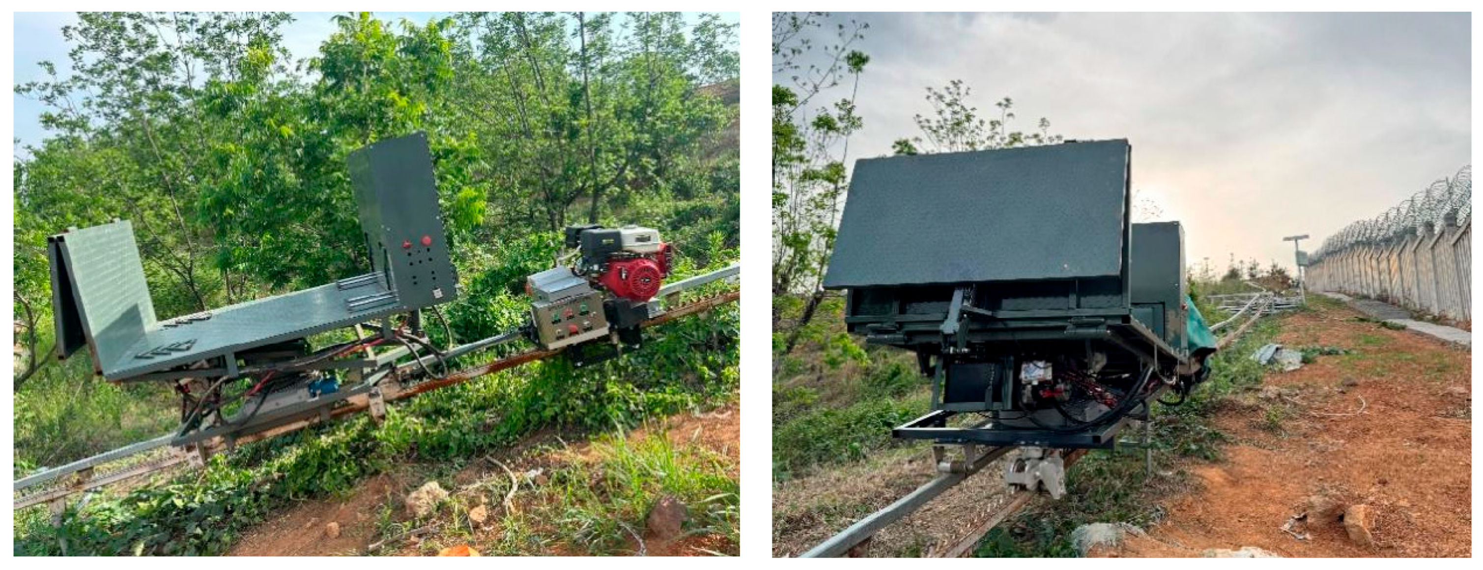
The physical experimental platform is shown in Figure 13, with its structure and parameter settings as described previously. The platform operated under typical sloping terrain track conditions. The controller collected attitude angle data in real time and yielded leveling control commands as outputs to achieve dynamic adjustment of the platform’s roll and pitch attitudes.

3.6.2. Experimental Conditions and Test Methods

Comparative experiments were conducted on a real-world mountainous rail platform. The aim was to further verify the effectiveness of the proposed attitude stabilization control method in a real-world rail transport environment and to ensure good correspondence with the simulation analyses presented above. The test subject was the same rail-mounted agricultural machinery transport platform system. Tests were conducted using two control strategies (i.e., conventional KF+PID and improved AKF+PID) under identical platform structures, load conditions, operating paths, and target attitude settings. The key field test conditions were as follows: slope range of 10–25°, load mass of 500 kg, operating speed of 0.35 m/s, and IMU sampling frequency of 100 Hz. Each test condition was repeated three times under the same platform structure, load condition, operating path, and target attitude setting. The differences in attitude regulation performance between the two methods under actual operating conditions were recorded.
The physical experiments were configured under the following scenarios to ensure consistency with the simulation conditions:
(1)
Static disturbance leveling experiment: With the platform at rest, an initial tilt was introduced via manual loading or by changing the track gradient locally. The aim was to test the control system’s ability to recover from deviations in roll and pitch angles.
(2)
Dynamic operation leveling experiments: The platform was run at low speed along a mountainous track, and attitude disturbances were introduced by factors such as track gradient changes, local unevenness, and mechanical vibrations. The aim was to test the platform’s attitude maintenance capability and disturbance resistance during actual operation.
During the experiments, the controller continuously acquired real-time roll ϕ and pitch θ angle data from the platform and yielded outputs corresponding to the leveling control commands. The following metrics were recorded and analyzed, and the in situ performance of the two control strategies was quantitatively evaluated:
(1)
Peak roll angle and peak pitch angle,
(2)
Time to attitude recovery and stabilization,
(3)
Root mean square (RMS) of the attitude fluctuations during the steady-state phase, and
(4)
RRI variations.
The aforementioned metrics are consistent with the dynamic response and risk assessment methods described in the simulation section above. During the experiments, these metrics were used to compare and analyze the dynamic response speed, steady-state fluctuation suppression capability, and operational risk control effectiveness of the conventional KF+PID and the improved AKF+PID methods under actual operating conditions.

3.6.3. Experimental Results and Analysis

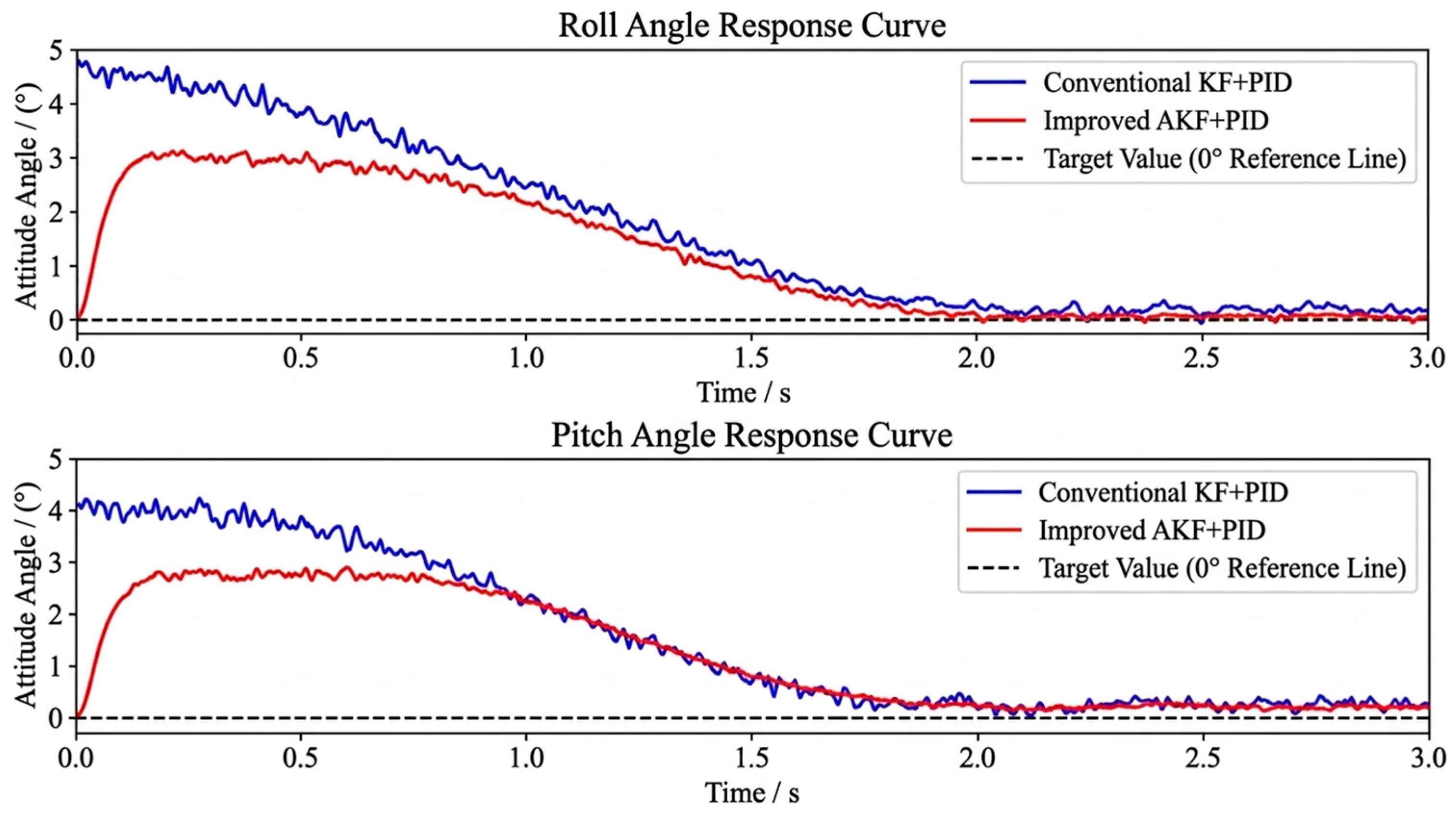
The measured time-domain response curves of the platform’s roll and pitch angles for the two control methods (i.e., conventional KF+PID and improved AKF+PID) under dynamic operating conditions are shown in Figure 14. The platform’s attitude fluctuates significantly under the combined effects of track gradient variations and operational vibrations. Compared with the conventional KF+PID method, the improved AKF+PID method enables the platform’s roll and pitch angles to converge more rapidly to a stable range, demonstrating its superior disturbance suppression and attitude recovery capabilities under actual rail transport conditions.
The improved AKF+PID method reduced the peak roll angle from 4.8° to 3.1° and the peak pitch angle from 4.1° to 2.7°, with corresponding decreases in stabilization times from 1.25 to 0.82 s and from 1.18 s to 0.79 s, respectively.
Further analysis of the attitude fluctuations during the steady-state phase revealed that under conventional KF+PID control, the RMS of the platform’s roll angle was approximately 0.62°, and that of the pitch angle was approximately 0.55°. Conversely, under improved AKF+PID control, the RMS of the roll angle decreased to 0.38°, and that of the pitch angle decreased to 0.34°. Comparative results for the steady-state phase indicate that under actual operating conditions, the improved AKF is more effective at suppressing the impact of measurement noise and vibration disturbances on attitude estimation, resulting in smaller fluctuation amplitudes and better smoothness of the control system.
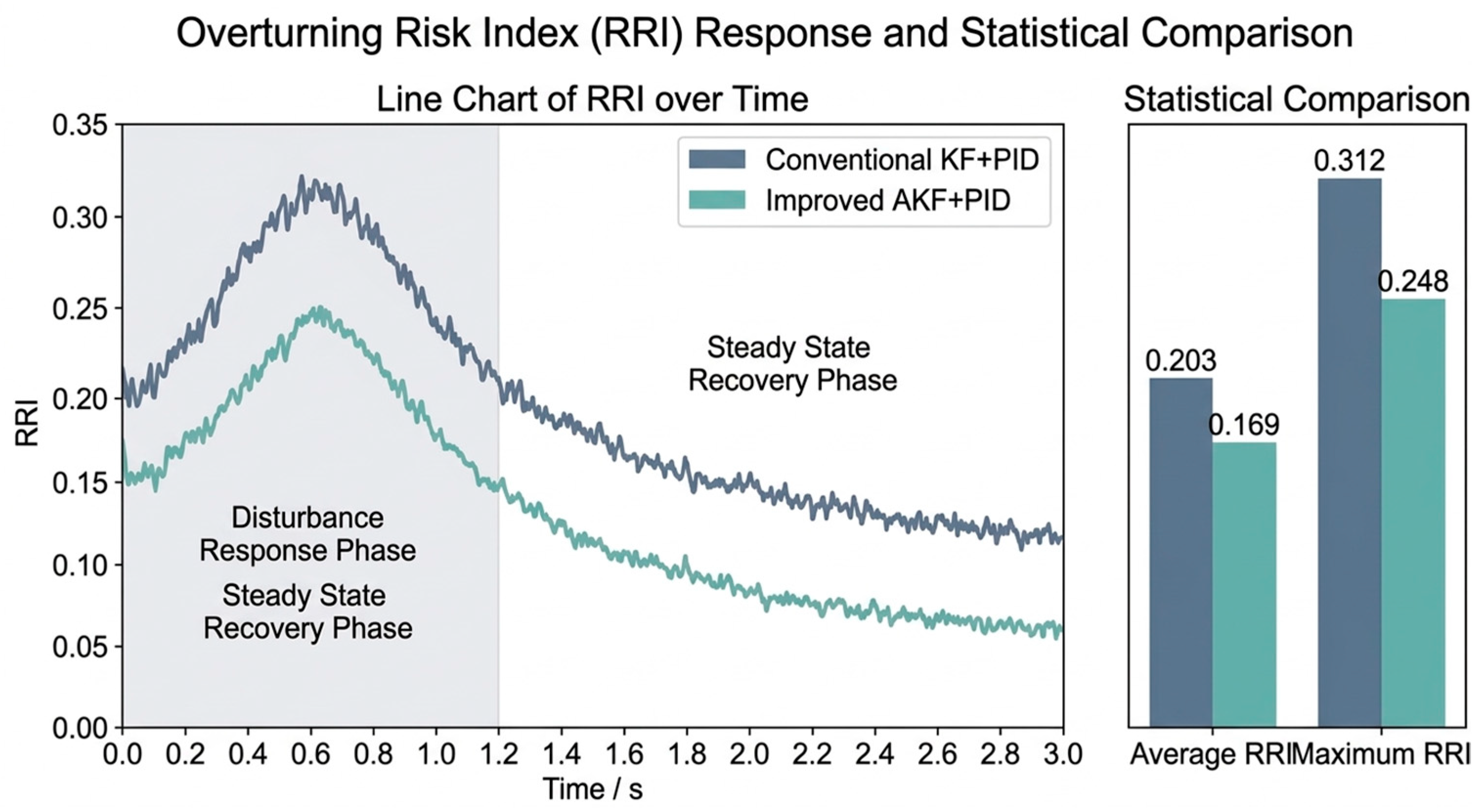
The variation curve of the RRI under actual operating conditions is shown in Figure 15. For the sudden-disturbance phase, the RRI of the conventional KF+PID method increased more rapidly and reached a higher peak, whereas the improved AKF+PID method suppressed the growth of attitude deviations more quickly and maintained the RRI at a relatively low level.
The statistical results of the improved AKF+PID method revealed a decrease in the average RRI from 0.203 to 0.169 and a decrease in the maximum RRI from 0.312 to 0.248. The hardware test results validate the effectiveness and robustness of the proposed method.

3.6.4. Discussion of the Experimental Results

The combined validation results of the simulation and experimental tests indicate the superior attitude stability control of the improved AKF+PID method. The simulation and field test results showed consistent trends: compared with the conventional KF+PID method, the improved AKF+PID method reduced attitude fluctuation, shortened stabilization time, and lowered the RRI. Its attitude fluctuation amplitudes and stabilization times during the hardware-in-the-loop experiments were slightly greater than those during the simulation, primarily because of practical factors such as hydraulic actuator hysteresis, structural assembly errors, and local track impacts. However, the proposed method still maintains a clear advantage over traditional approaches in terms of dynamic response speed, steady-state fluctuation suppression, and rollover risk control, demonstrating its strong engineering adaptability.
It should be noted that this study mainly compared the improved AKF+PID method with the conventional KF+PID method, while advanced estimation methods such as EKF, UKF, ANN, and LSTM were not included in the present experimental comparison. For the investigated platform, the proposed method is suitable for low-speed rail-based agricultural transport under normal slope variation and small-range leveling conditions, with the advantages of low computational complexity, real-time feasibility, good interpretability, and no requirement for additional contact-force sensors or large amounts of labeled training data. Further validation is still needed under extreme slopes, severe load shifts, sensor delay or failure, strongly nonlinear coupled dynamics, and more diverse estimation/control strategies.

4. Conclusions

Attitude modeling, state estimation, closed-loop control, and risk assessment were conducted for a rail-based agricultural machinery transport platform in response to the issues commonly encountered in hilly and mountainous terrain, such as attitude deviations, insufficient attitude perception accuracy, and high operational risks. The main conclusions of this study are as follows:
(1)
A dynamic model of the platform’s roll and pitch attitudes was established by integrating the platform’s structural characteristics, variations in load distribution, and the mechanism of center-of-mass displacement. A corresponding discrete state-space representation was subsequently formulated, providing a theoretical foundation for attitude estimation and closed-loop control.
(2)
Building upon the traditional KF method, an adaptive noise covariance update method based on observation residuals was developed to facilitate online estimation of the platform’s attitude states. The simulation results revealed the high estimation accuracy and estimation robustness of the improved AKF method under complex disturbance conditions.
(3)
A dual-channel PID closed-loop leveling control strategy was developed on the basis of the improved AKF attitude feedback. Simulation and field tests revealed the superior performance of the improved AKF+PID over the conventional KF+PID in terms of dynamic response speed, overshoot suppression, and attitude recovery capability. These results validate the dynamic leveling performance of the proposed method under actual track disturbance conditions.
(4)
The RRI was integrated into the quantitative evaluation of operational safety. The results of the Monte Carlo simulation and field tests indicate the superior performance of the proposed method in suppressing attitude fluctuations and reducing overall operational risk.
The main advantage of the improved AKF+PID method for attitude stabilization control lies in its capability to enhance attitude estimation robustness, dynamic leveling performance, and operational risk mitigation; it moves beyond the task of merely reducing steady-state errors. These capabilities are essential for agricultural machinery transport platforms on hilly and mountainous terrain under complex disturbance conditions. Nevertheless, this study is still based on simplifications of certain models and does not fully consider the nonlinearity of hydraulic actuators, valve control dynamics, friction hysteresis, or strong roll–pitch coupling. Moreover, the scale of physical testing and the range of operating conditions applied in this research still need to be expanded. Future work will expand the research scope by considering the platform’s attitude stabilization control method and incorporating more comprehensive physical testing conditions and higher-fidelity nonlinear coupled models.

Author Contributions

The seven authors developed the research approach together. Conceptualization, Y.S. and Y.T.; methodology, Y.S. and M.X.; visualization, Y.S. and Y.T.; validation, M.X. and J.D.; writing—original draft preparation, Y.S. and M.X.; software, Y.S. and Y.T.; formal analysis, Y.S. and W.W.; writing—review and editing, M.X. and J.D.; funding acquisition, M.X. and Y.Z.; investigation, Y.Z. and J.D.; resources, M.X. and G.G.; supervision, W.W. and G.G.; data curation, G.G. and W.W.; project administration, J.D. and Y.Z. All authors have read and agreed to the published version of the manuscript.

Funding

This research was funded by the National Key Research and Development Program of China (Grant No. 2022YFD2001805), the Jiangsu Modern Agricultural Equipment and Technology Demonstration and Promotion Project (Grant No. NJ2025-14), the Fundamental Research Funds for the Central Universities (Grant No. KYPT2025004), and the National Undergraduate Innovation and Entrepreneurship Training Program (Grant No.202510307109S).

Institutional Review Board Statement

Not applicable.

Data Availability Statement

The original contributions presented in this study are included in the article. Further inquiries can be directed to the corresponding author(s).

Acknowledgments

This study received technical support from the College of Engineering at Nanjing Agriculture University, including the licensed software of MATLAB R2025a.

Conflicts of Interest

The authors declare no conflicts of interest.

Abbreviations

The following abbreviations are used in this manuscript:
AKFAdaptive Kalman filter
PIDProportional–integral–derivative
IMUInertial measurement unit
RRIRollover risk index
RMSERoot mean square error
KFKalman filter

References

  1. Ding, R.; Qi, X.; Chen, X.; Mei, Y.; Li, A. The Current Development status of Agricultural Machinery Chassis in Hilly and Mountainous Regions. Appl. Sci. 2025, 15, 7505. [Google Scholar] [CrossRef]
  2. Wang, B.; Zhu, J.; Chai, X.; Liu, B.; Zhang, G.; Yao, W. Research status and development trend of key technology of agricultural machinery chassis in hilly and mountainous areas. Comput. Electron. Agric. 2024, 226, 109447. [Google Scholar] [CrossRef]
  3. Li, Z.; Hong, T.; Lü, S.; Liu, Y. Research Progress on Self-propelled Electric Monorail Transport Equipment for Mountainous Orchards. Mod. Agric. Mach. 2020, 41, 2–9. (In Chinese) [Google Scholar]
  4. Briales, E.; Urda, P.; Escalona, J.L. Track frame approach for heading and attitude estimation in operating railways using on-board MEMS sensor and encoder. Measurement 2021, 184, 109898. [Google Scholar] [CrossRef]
  5. González-Carbajal, J.; Urda, P.; Muñoz, S.; Escalona, J.L. Estimation of the trajectory and attitude of railway vehicles using inertial sensors with application to track geometry measurement. Veh. Syst. Dyn. 2024, 62, 837–863. [Google Scholar] [CrossRef]
  6. Dahmani, H.; Chadli, M.; Rabhi, A.; El Hajjaji, A. Detection of impending vehicle rollover with road bank angle consideration using arobust fuzzy observer. Int. J. Autom. Comput. 2015, 12, 93–101. [Google Scholar] [CrossRef]
  7. Phanomchoeng, G.; Rajamani, R. New Rollover Index for Detection of Tripped and Un-Tripped Rollovers. In Proceedings of the 2011 50th IEEE Conference on Decision and Control and European Control Conference (CDC-ECC); IEEE: Orlando, FL, USA, 2011; pp. 7440–7445. [Google Scholar] [CrossRef]
  8. Chen, B.C.; Peng, H. A Real-time Rollover Threat Index for sports Utility Vehicles. In Proceedings of the 1999 American Control Conference; IEEE: San Diego, CA, USA, 1999; Volume 2, pp. 1233–1237. [Google Scholar]
  9. Xiong, L.; Xia, X.; Lu, Y.; Liu, W.; Gao, L.; Song, S.; Han, Y.; Yu, Z. IMU-Based Automated Vehicle slip Angle and Attitude Estimation Aided by Vehicle Dynamics. Sensors 2019, 19, 1930. [Google Scholar] [CrossRef]
  10. Sabatini, A.M. Quaternion-Based Extended Kalman Filter for Determining Orientation by Inertial and Magnetic sensing. IEEE Trans. Biomed. Eng. 2006, 53, 1346–1356. [Google Scholar] [CrossRef]
  11. Sabatini, A.M. Kalman-Filter-Based Orientation Determination Using Inertial/Magnetic sensors: Observability Analysis and Performance Evaluation. Sensors 2011, 11, 9182–9206. [Google Scholar] [CrossRef]
  12. Valenti, R.G.; Dryanovski, I.; Xiao, J. Keeping a Good Attitude: A Quaternion-Based Orientation Filter for IMUs and MARGs. Sensors 2015, 15, 19302–19330. [Google Scholar] [CrossRef]
  13. Mahony, R.; Hamel, T.; Pflimlin, J.M. Nonlinear complementary filters on the special orthogonal group. IEEE Trans. Autom. Control 2008, 53, 1203–1218. [Google Scholar] [CrossRef]
  14. Chiella, A.C.B.; Teixeira, B.O.S.; Pereira, G.A.S. Quaternion-Based Robust Attitude Estimation Using an Adaptive Unscented Kalman Filter. Sensors 2019, 19, 2372. [Google Scholar] [CrossRef]
  15. Li, W.; Wang, J. Effective Adaptive Kalman Filter for MEM S-IMU/Magnetometers Integrated Attitude and Heading Reference systems. J. Navig. 2013, 66, 99–113. [Google Scholar] [CrossRef]
  16. Del Rosario, M.B.; Khamis, H.; Ngo, P.; Lovell, N.H.; Redmond, S.J. Computationally-Efficient Adaptive Error- State Kalman Filter for Attitude Estimation. IEEE Sens. J. 2018, 18, 9332–9342. [Google Scholar] [CrossRef]
  17. Zhou, Q.; Li, Z.; Yu, G.; Li, H.; Zhang, N. A novel adaptive Kalman filter for Euler-angle-based MEM S IMU/magnetometer attitude estimation. Meas. Sci. Technol. 2021, 32, 045104. [Google Scholar] [CrossRef]
  18. Odry, Á.; Kecskes, I.; Sarcevic, P.; Vizvari, Z.; Toth, A.; Odry, P. A Novel Fuzzy-Adaptive Extended Kalman Filter for Real-Time Attitude Estimation of Mobile Robots. Sensors 2020, 20, 803. [Google Scholar] [CrossRef]
  19. Chen, J.; Cui, B.; Wei, X.; Zhu, Y.; Sun, Z.; Liu, Y. Robust Attitude Estimation for Low-Dynamic Vehicles Based on MEMS-IMU and External Acceleration Compensation. Sensors 2024, 24, 4623. [Google Scholar] [CrossRef]
  20. Li, Y.; Jia, H.; Qi, J.; Sun, H.; Tian, X.; Liu, H.; Fan, X. An Acquisition Method of Agricultural Equipment Roll Angle Based on Multi-Source Information Fusion. Sensors 2020, 20, 2082. [Google Scholar] [CrossRef]
  21. Hu, L.; Yang, W.; He, J.; Zhou, H.; Zhang, Z.; Luo, X.; Zhao, R.; Tang, L.; Du, P. Roll angle estimation using low cost MEMS sensors for paddy field machine. Comput. Electron. Agric. 2019, 158, 183–188. [Google Scholar] [CrossRef]
  22. Yu, J.H.; Park, J.K.; Cheon, S.H.; Byeon, S.J.; Lee, J.W. Development of a rolling angle estimation algorithm to improve the performance of implement leveling-control systems for agricultural tractors. Adv. Mech. Eng. 2022, 14, 16878132221138310. [Google Scholar] [CrossRef]
  23. Zhu, Y.; Cui, B.; Yu, Z.; Gao, Y.; Wei, X. Tillage Depth Detection and Control Based on Attitude Estimation and Online Calibration of Model Parameters. Agriculture 2024, 14, 2130. [Google Scholar] [CrossRef]
  24. Ou, J.; Fu, Q.; Tang, R.; Du, J.; Xu, L. Path Tracking Control of a Tractor on a sloping Road with steering Compensation. Agriculture 2023, 13, 2160. [Google Scholar] [CrossRef]
  25. Mazhar, M.K.; Khan, M.J.; Bhatti, A.I.; Naseer, N. A Novel Roll and Pitch Estimation Approach for a Ground Vehicle stability Improvement Using a Low Cost IMU. Sensors 2020, 20, 340. [Google Scholar] [CrossRef]
Figure 1. Schematic of the overall structure of the rail-based agricultural machinery transport platform system: (1) main hydraulic cylinder, (2) hydraulic rod, (3) upper steel frame, (4) transport platform, (5) hydraulic tailgate, (6) rear stop block, (7) IMU sensor, (8) lower steel frame, (9) rotation oil circuit, (10) middle steel frame, (11) hydraulic rotation mechanism, (12) bottom of hydraulic rotation mechanism, (13) transport platform pulley, (14) engine, and (15) track.
Agriculture 16 01123 g001
Figure 2. Schematic of the key mechanical structure of the transport platform: (1) large tailgate, (2) small tailgate, (3) tailgate hydraulic cylinder, (4) oil reservoir, (5) rear stop block hydraulic master cylinder, and (6) front stop block.
Agriculture 16 01123 g002
Figure 3. Schematic of platform attitude adjustment and stability control.
Agriculture 16 01123 g003
Figure 4. Schematic of the relationship between the platform’s center of mass displacement and attitude stability: (a) steady state condition; (b) platform approaching a critical rollover state after roll motion.
Agriculture 16 01123 g004
Figure 5. Schematic of the platform’s roll force analysis: (a) platform stability in the steady horizontal state; (b) force analysis of the platform during roll motion.
Agriculture 16 01123 g005
Figure 6. Flowchart of the improved AKF algorithm.
Agriculture 16 01123 g006
Figure 7. Control architecture of the improved AKF–PID attitude stabilization system, including attitude measurement, state estimation, PID control, hydraulic actuation, platform response, and RRI evaluation.
Agriculture 16 01123 g007
Figure 8. Comparison of roll angle estimates (Experimental/Data Collection Year: 25 January 2026).
Agriculture 16 01123 g008
Figure 9. Comparison of pitch angle estimates (Experimental/Data Collection Year: 25 January 2026).
Agriculture 16 01123 g009
Figure 10. Roll angle control response curve (Experimental/Data Collection Year: 4 February 2026).
Agriculture 16 01123 g010
Figure 11. Pitch control response curve (Experimental/Data Collection Year: 4 February 2026).
Agriculture 16 01123 g011
Figure 12. Distribution of Monte Carlo random gradient simulation results (Experimental/Data Collection Year: 16 February 2026).
Agriculture 16 01123 g012
Figure 13. On-site view of the physical test platform (Experimental/Data Collection Year: 2 March 2026).
Agriculture 16 01123 g013
Figure 14. Time-domain response curves for the platform’s roll and pitch angles under actual operating conditions (Experimental/Data Collection Year: 4 March 2026).
Agriculture 16 01123 g014
Figure 15. Curve trends of changes in the platform overturn risk index under actual operating conditions (Experimental/Data Collection Year: 6 March 2026).
Agriculture 16 01123 g015
Table 1. Key parameter settings for the transport platform system.
Parameter NameCode/ModelValue or Description
Platform dimensions L × W × H 3000 × 1500 × 1500   m m
Maximum load capacity M m a x 800   k g
Track type Dual-rail support type
Leveling range ± α ± 10 °
Actuator type Hydraulic actuator-type leveling mechanism
Actuator arrangement Two at the front and two at the rear, four in total
Maximum actuator stroke Δ l m a x 0.3665 m
Maximum actuator load F m a x 8915 N
Attitude sensorIMU, Xsens MTi-300 AHRS
(Enschede, The Netherlands)
Used to measure roll angle, pitch angle, and angular velocity; roll/pitch accuracy: 0.2° RMS; heading accuracy: 1° RMS; gyroscope range: ±450°/s; accelerometer range: ±20 g
Sampling frequency f s 100 Hz used in field tests
Control strategy Modified AKF+PID
Target attitude ϕ d , θ d Roll angle and pitch angle stabilized around 0°
Table 2. Main simulation parameter settings.
ParametersSymbolValue
Sampling period T s 0.01 s
Simulation time T 10 s
Initial roll angle ϕ 0
Initial pitch angle θ 0
Target roll angle ϕ d
Target pitch angle θ d
Number of Monte Carlo samples N 100
Range of random gradient perturbations γ s 10–30°
Table 3. Key parameter settings for the improved AKF+PID method.
ParametersSymbolValue
Q Initial value of system noise covariance0.02 I
R 0 Initial observed noise covariance0.8 I
α Update coefficient for observed noise covariance0.02
β Adaptive update weight for system noise covariance0.15
R m i n Lower bound of observed noise covariance0.01
R m a x Upper bound of observed noise covariance0.49
K p ϕ Roll channel proportional gain2.5
K i ϕ Roll channel integral gain0.8
K d ϕ Roll channel derivative gain0.3
K p θ Pitch channel proportional gain2.2
K i θ Pitch channel integral gain0.7
K d θ Pitch channel derivative gain0.25
Table 4. Comparison of attitude angle estimation errors (Experimental/Data Collection Year: 25 January 2026).
Algorithm Roll Angle
RMSE
Roll Angle
MAE
Elevation and Azimuth RMSEMaximum Absolute Error in Pitch and Roll
Traditional KF 1.2684°3.1269°0.7256°2.0244°
Improved AKF0.8670°2.3723°0.4629°1.5263°
Table 5. Comparison of attitude control performance (Experimental/Data Collection Year: 4 February 2026).
RollControl AlgorithmsStabilization TimeMaximum OvershootSteady-State Error
RollConventional KF+PID0.6250 s2.0229°0.0962°
RollImproved AKF+PID0.3830 s1.4300°0.1023°
PitchConventional KF+PID0.6930 s1.8417°0.0615°
PitchImproved AKF+PID0.4110 s1.2990°0.0816°
Table 6. RRI value range categories.
RRI RangeStable Condition
<0.6Stable
0.6–0.8Critical
>0.8High risk
Table 7. Summary of the Monte Carlo simulation results (Experimental/Data Collection Year: 16 February 2026).
Control MethodsAverage RRIMaximum RRI
Conventional KF+PID0.18610.3255
Improved AKF+PID0.15060.3119
Disclaimer/Publisher’s Note: The statements, opinions and data contained in all publications are solely those of the individual author(s) and contributor(s) and not of MDPI and/or the editor(s). MDPI and/or the editor(s) disclaim responsibility for any injury to people or property resulting from any ideas, methods, instructions or products referred to in the content.