Article

Defect Analysis and Core-Parameter Optimization of a Spiral Sugarcane Lifter Based on Rigid–Flexible Coupling


1
College of Intelligent Manufacturing, Anhui Science and Technology University, Chuzhou 233100, China
2
College of Engineering, Nanjing Agricultural University, Nanjing 210031, China
*
Author to whom correspondence should be addressed.
Agriculture 2026, 16(10), 1100; https://doi.org/10.3390/agriculture16101100
Submission received: 8 April 2026 / Revised: 14 May 2026 / Accepted: 14 May 2026 / Published: 16 May 2026
(This article belongs to the Section Agricultural Technology)

Abstract

As a key component of sugarcane harvesting machinery, the spiral sugarcane lifter (SSL) enhances harvesting quality by lifting lodged sugarcane (LSC) into a posture suitable for stalk-base cutting and feeding. To improve the SSL’s lifting performance for LSC, this study developed a rigid–flexible coupling (RFC) simulation model of the sugarcane–SSL interaction and conducted kinematic and force analyses to identify the main shortcomings of the original design. Critical structural and operational parameters affecting lifting performance–including the lifting roller pitch, roller diameter, roller inclination angle, and lifter shoe length—were redesigned using mechanism-based constraints and simulation-assisted evaluation. The optimized SSL exhibited increased lifting speed and stability under low–speed, severe–lodging conditions. Under side-forward lodging (side deflection angle = 30°), the average maximum vertical height of the centroid (VHC) increased by 40.36%, and paired comparisons across three simulated lodging-angle scenarios showed significant improvement. Field tests under severe lodging at 0.55 m/s (≈2 km/h) yielded an average absolute simulation–to–field error of 5.37%. These findings support the effectiveness of the proposed parameter redesign for the tested medium-size harvester, although further validation is required under higher forward speeds, greater biomass throughput, and more variable soil conditions.

1. Introduction

Sugarcane is an important raw material for sugar and bioenergy production and is widely cultivated in tropical and subtropical regions [1,2,3,4]. Mechanized sugarcane harvesting has developed rapidly, but the suitable harvester type and operational speed depend on field scale, terrain, crop posture, and regional agronomic conditions [5,6,7,8,9,10]. In the main sugarcane-producing areas of southern China, many fields are located on hilly and sloping terrain with relatively small field blocks. Moreover, seasonal monsoon rainfall and typhoons frequently cause varying degrees of sugarcane lodging. Consequently, medium-size sugarcane harvesters are often operated at relatively low forward speeds in lodged fields, consistent with the low-speed parameter ranges used in lifter and crop-divider studies [7,9]. Under such conditions, insufficient lifting of lodged stalks can reduce stalk-base cutting quality, increase feeding instability, and result in harvesting losses [11,12,13,14].
Existing studies on sugarcane mechanization have addressed crop dividers and lifters, stalk-base cutting, soil–machine–crop interactions, ratoon preservation, biomass feeding, and harvesting losses [7,9,10,11,12,13,14,15,16,17,18,19]. Regarding spiral lifters, Song et al. investigated two-stage spiral lifting mechanisms and their influence on sugarcane lifting quality [10,11,12]. Hu et al. performed virtual prototype simulations of sugarcane lifters and found that forward speed was a key factor affecting the vertical height of the centroid (VHC) [13]. Zhang et al. and Gao et al. developed virtual prototype or mechanical models for sugarcane lifter operation [14,15], while Ma et al. measured the physical and mechanical properties of GuiTang 46 ratoon sugarcane stalks to support modeling [16]. Bai et al. reported that the scroll structure and installation angle substantially affect the lifting performance of crop dividers [17]. These studies provide useful references, yet many SSL geometric parameters are still primarily chosen based on engineering experience. Therefore, a clear mechanism–based framework for parameter redesign is needed for lodged sugarcane in hilly field conditions.
Rigid–flexible coupling (RFC), multi-body dynamics, CFD–DEM coupling, and vibration/field sensing have become important tools for analyzing crop–machine interactions and optimizing agricultural equipment [20,21,22,23]. Specifically, in RFC simulation of sugarcane and similar stalk crops, Cui et al. performed flexible modeling of corn stalks using ANSYS2011 and ADAMS2011 [24], Pu et al. established a flexible sugarcane body model in ADAMS for lifter simulations [25], and Xie et al. analyzed sugarcane movement under chopper components using finite element simulation [26]. Friction and lifting–performance studies of spiral crop mechanisms have also informed lifter parameter selection [27], while cutting quality, losses, and impurity issues in mechanized sugarcane harvesting have been evaluated in field studies [28]. Coupled numerical simulation with experimental validation has been applied to other agricultural feeding devices [22,23,29,30,31,32], and lightweight intelligent sensing has been used for real–time field crop monitoring [33]. Recent spike–toothed crop–divider designs further provide useful insights for structural redesign [34,35]. Collectively, these studies indicate that mechanism-based simulation, when combined with transparent assumptions and field validation, can effectively support the optimization of complex agricultural machinery.
Focusing on severely lodged sugarcane, this study first analyzes the deficiencies of the original SSL using an RFC model and kinematic analysis. Key structural parameters are then redesigned according to force and kinematic constraints, existing experimental data, and field operation requirements. Finally, the optimized lifter is compared with the original design through simulations and validated in field tests. Therefore, the main contribution of this work lies in providing a simulation–supported, mechanism-guided parameter redesign of an existing SSL, rather than proposing a completely new harvesting principle or a global numerical optimization approach.

2. Materials and Methods

2.1. Structure and Working Principle of the Spiral Sugarcane Lifter (SSL)

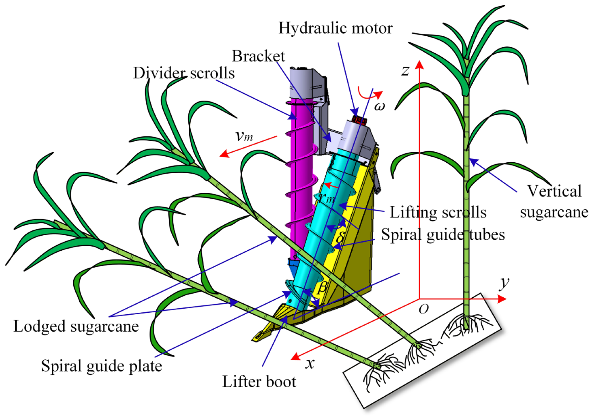
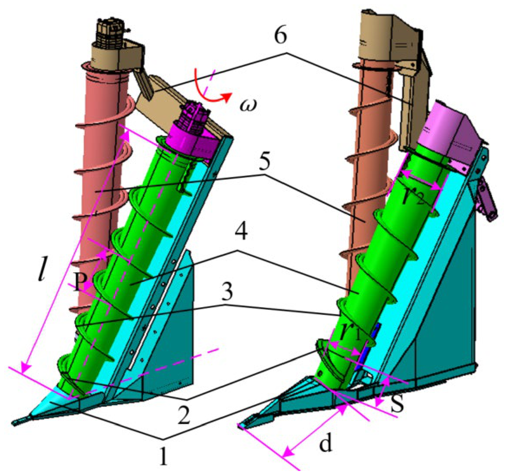
The structural composition of the SSL is shown in Figure 1 and mainly consists of a frame, lifter shoe, dividing drum, lifter drum, and hydraulic motor. Among these components, the lifter drum and dividing drum are the key operational elements, both equipped with helical blades. Each harvester is fitted with two sets of lifting devices, symmetrically installed on the left and right sides of the feed inlet.
During operation, the lifter drum and dividing drum rotate around their central axes while advancing with the harvester. As the harvester moves forward, the lodged sugarcane (LSC) first contacts the lifter drum. Driven by the rotation of the lifter drum and the forward motion of the harvester, the LSC is gradually lifted along the helical blades and guided toward the center of the working row. The dividing drum advances simultaneously, lifting and partially separating the LSC in adjacent rows to prevent damage from the harvester wheels. When lifting the LSC, it is not necessary to fully upright the stalks; they only need to be raised to a suitable height and posture so that the base cutter can cleanly cut the stalk base above the soil surface, thereby reducing cutting losses and minimizing ratoon damage.

2.2. Kinematic Analysis of Sugarcane Stalks and the SSL

2.2.1. Lodging Postures of Sugarcane

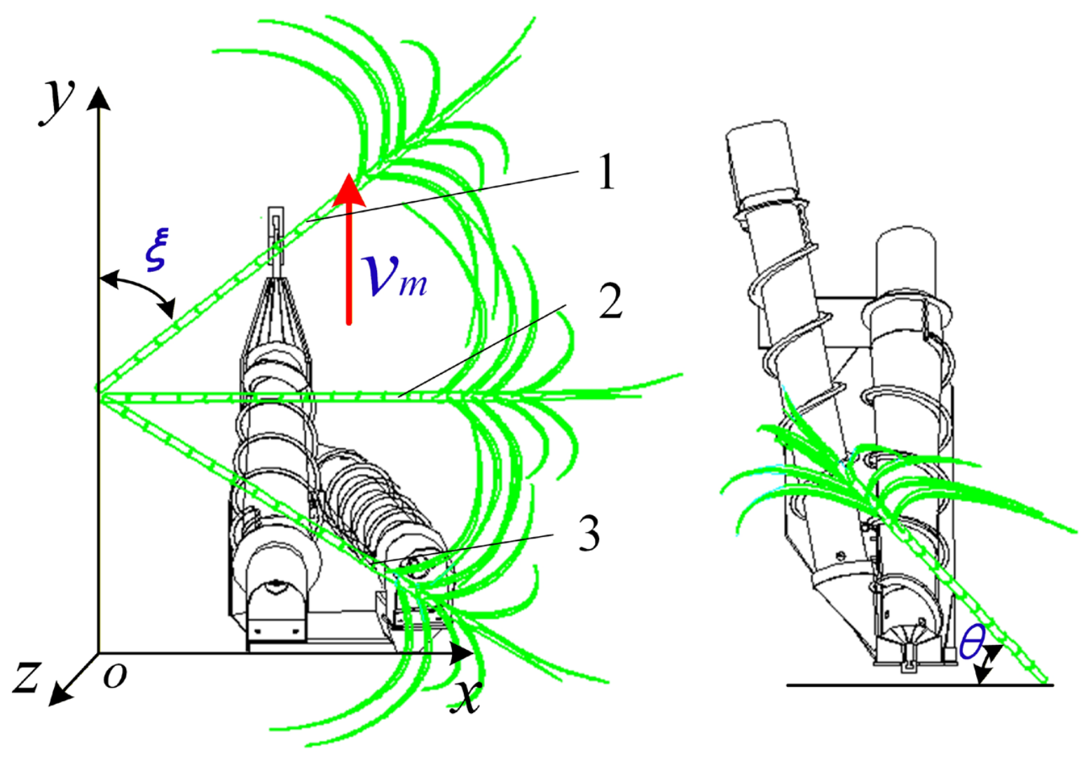
The presence of LSC directly increases the difficulty of mechanized sugarcane harvesting. To further investigate LSC, it is essential to classify lodging forms according to the relative position between the SSL and the LSC. As shown in Figure 2, ξ denotes the side deflection angle (SDA), and θ denotes the lodging angle (LA). The SDA is defined as the angle between the LSC and the forward direction of the SSL, whereas the LA is defined as the angle between the sugarcane stalk and the direction of its radial projection. Based on the SDA, LSC can be classified mainly into side lodging, forward lodging, backward lodging, side-forward lodging, and side-backward lodging. According to the LA, the degree of sugarcane lodging is divided into three levels [9]: slight lodging (θ ≥ 60°), moderate lodging (30° ≤ θ < 60°), and severe lodging (0° ≤ θ < 30°).

2.2.2. Kinematic Analysis of the SSL

The conical drum and helical blades are the key components of the lifter drum. Properly designed parameters allow the LSC to rise along the helical blades as the drum rotates, enabling rapid and stable lifting of the stalks. A review of the relevant literature indicates that theoretical research on sugarcane helical mechanisms remains challenging, and the design of such helical lifting mechanisms is still largely based on empirical experience [15]. In previous studies, researchers combined the working principle of the SSL–that is, the lifter drum rotates around its axis while advancing with the harvester–to derive the spatial motion equation of any point on the lifter as follows:
v x = v n t cos β cos δ v m t v y = v n t cos β sin δ v z = v n t sin δ
where X is the displacement of the contact point in the x–axis direction, m; t is time, s; β is the angle between the SSL drum and the horizontal plane, °; δ is the inclination angle of the spiral, °; Y is the displacement of the contact point in the Y–axis direction, m; Z is the displacement of the contact point in the Z direction, m. Since the radius of the SSL drum varies at different positions, the linear velocity of the contact point varies at different moments as the SSL drum rotates. With the continuous advancement of the harvester, the velocity equation of the contact point is
v x = d X d t = v n cos β cos δ v m v y = d Y d t = v n cos β sin δ v z = d Z d t = v n sin δ
where vx is the velocity of the contact point along the x–axis (m/s), vy is the velocity along the y–axis (m/s), and vz is the velocity along the z–axis (m/s). Although the above equation describes a spatial spiral curve, analysis of the field interaction between LSC and the SSL shows that sugarcane is subjected to the anchoring moment from the stalk base and root stool in soil when it comes into contact with the helical blade of the SSL. Consequently, the stalk does not rotate freely around the lifter drum and primarily undergoes axial movement along the lifter drum. Therefore, the motion characteristics of the contact point cannot be fully explained by the geometric spiral equation alone.
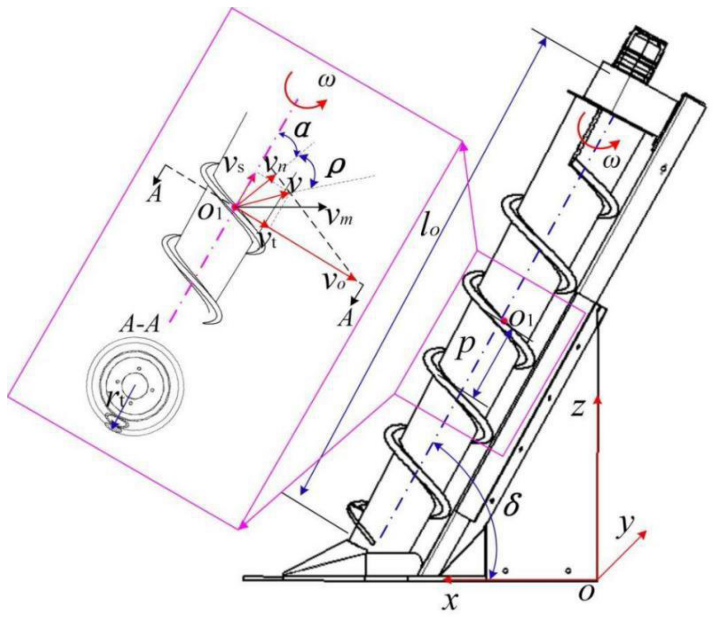
Building on previous studies and the formation principle of spirals, this paper conducts a kinematic analysis of the sugarcane stalk and the lifter drum during the lifting process. During field lifting, the sugarcane stalk comes into contact with the working surface of the helical blade and moves axially along the lifter drum while rotating about the stalk-base anchorage point. Because the pitch of the helical blades on the SSL is constant, the motion of the contact point between the LSC and the helical blade can be approximated as the motion of a particle along an equidistant conical spiral. The relative motion of the sugarcane stalk with respect to the helical blade on the conical drum at a given moment is shown in Figure 3, where the contact point between the sugarcane and the helical blade of the lifter drum is denoted as O1.
At this point, the LSC is primarily subjected to friction from the helical blade. The direction of the force exerted by the helical blade on the sugarcane stalk should form a friction angle ρ with its normal line. Neglecting the influence of the harvester’s forward speed on the lifting process, the rotational speed of the drum is set as ω. Assuming that at a radius r of the conical drum, the contact point between the sugarcane stalk and the helical blade of the drum is O1, the sugarcane generates a linear velocity v0 under the rotation of the SSL drum. This velocity represents the convected motion of the contact point relative to the reference frame, and its direction is along the tangent to the rotation of the contact point. Thus, we have
v 0 = ω r
At contact point O1 between the sugarcane and the drum blade, a relative sliding velocity vn is generated with respect to the helical surface, which is parallel to the tangential direction of the helix at the contact point. Due to the friction between the sugarcane stalk and the blade, the direction of the resultant velocity (i.e., the absolute velocity) v at this contact point should deviate from the normal direction by the friction angle ρ, thereby giving the resultant velocity v. This velocity v is composed of the axial motion along the drum and the radial circumferential motion, which forces the sugarcane to be lifted upward and gathered toward the inter-row space. The radial component gives the circumferential velocity vt, and the axial component is the velocity vs, as shown in Figure 3.
v s = v cos ( α + ρ )
v t = v sin ( α + ρ )
From the kinematic analysis diagram of the stalk at the contact point, the absolute velocity vm and the resultant velocity v of contact point O1 can be obtained as follows:
v m = v 0 sin α
v = v n cos ρ
From the geometric relationship of the angles, the axial velocity vs. can be expressed as follows:
v s = v 0 sin α cos β cos ( α + ρ )
Based on the above analysis, it can be concluded that the velocity vt impedes the motion of the sugarcane, while v0 is the velocity imparted by the rotating drum to drive the sugarcane movement.
v s = v 0 sin α cos β cos ( α + ρ )
v s = P n 60 cos 2 α ( 1 tan ρ tan α )
From the definition of the coefficient of friction between the sugarcane stalk and the helical blade of the lifting drum, it follows that
f = tan ρ
cos α = 1 1 + ( P 2 π r ) 2
tan α = P 2 π r
By combining the above equations, we obtain
v s = P n 60 cos 2 α ( 1 tan ρ tan α )
v s = P n 60 1 f P 2 π r ( P 2 π r ) 2 + 1
Similarly, we can obtain
v t = P n 60 f + P 2 π r ( P 2 π r ) 2 + 1
where P is the pitch of the helical blade (mm); n is the rotational speed of the lifting drum (r/min); f is the coefficient of friction between the sugarcane stalk and the helical blade on the lifting drum; α is the helix angle of the helical blade (°).
Since the harvester moves forward at a speed vm during operation, the sugarcane is fed into the lifter at the same relative speed. Thus, the following relationship can be derived:
v s = P n 60 1 f P 2 π r ( P 2 π r ) 2 + 1 + v m cos δ
v t = P n 60 f + P 2 π r ( P 2 π r ) 2 + 1 + v m sin δ
Based on the above analysis and Equations (15) and (17), it can be concluded that the lifting velocity of the LSC by the SSL is primarily determined by the drum radius and rotational speed, the pitch and helix angle of the helical blade, the coefficient of friction between the LSC and the drum, and the inclination angle of the SSL relative to the ground. When the SSL inclination angle is fixed, the lifting velocity is directly proportional to the drum radius, rotational speed, and helical blade pitch, and inversely proportional to the coefficient of friction.

2.2.3. Lifting Analysis Under Different Lodging Postures

The lodging of sugarcane is intricate and complex, and the relative position between the LSC and the SSL may be a key factor affecting lifting quality [9]. Therefore, it is important to analyze the lifting process under different lodging postures. Song et al. conducted a series of studies on the mechanical and kinematic interactions between spiral lifters and lodged sugarcane during the forward motion of the harvester [10,11,12,27]. As indicated by the preceding analysis, when sugarcane exhibits pure forward or reverse lodging, the travel direction of the harvester is aligned with the lodging direction of the cane, and the lodged stalks may have limited contact with the SSL. Furthermore, when stalks exhibit lateral-forward or lateral-reverse lodging with a small angle relative to the machine travel direction, they may also have limited contact with the SSL. These scenarios fall outside the primary scope of this study.
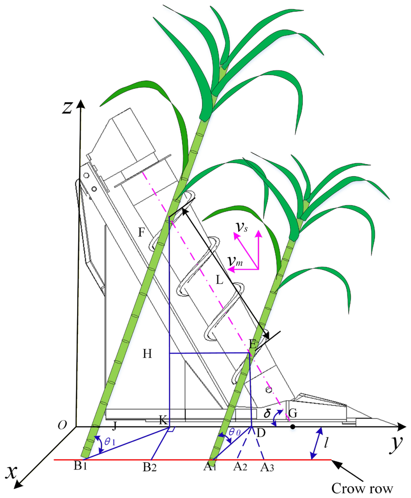
Taking the SSL as the reference frame, a spatial coordinate system was established to represent the sugarcane before and after lifting by the SSL, as shown in Figure 4. In the figure, the cane on the right represents LSC, while the cane on the left represents the lifted state. Assuming the initial LA for all three cane orientations is θ0, it can be observed that after lifting, the LA changes from θ0 to θ1. The contact point of interaction between the LSC and the conical lifting drum moves from E to F. The effective length of the conical drum during lifting is L. The projections of points E and F onto the Oy-axis are K and D, respectively. Perpendiculars drawn from K and D to the centerline of the crop row yield points B2 and A2. According to the definition of the sugarcane LA, point A2 corresponds to the lodging posture in lateral lodging. In the diagram, positions A1, A2, and A3 represent the postures of lateral-forward lodged, laterally lodged, and lateral-reverse lodged sugarcane, respectively. Different lodging postures result in distinct projection curves onto the Oxy–plane. As shown in Figure 4, the projections of the three postures before lifting are A1D, A2D, and A3D, respectively, while after lifting, the projection for all cases is B1K.
Based on the geometric relationship of the projections, it can be derived that: when the sugarcane is in lateral-forward lodging, the forward displacement of the harvester during the entire process of the lodged cane moving from point E to point F is B2A1, which is less than KD. In the case of lateral lodging, the harvester’s displacement is B2A2, which is equal to KD. For lateral-reverse lodging, the harvester’s displacement is B2A3, which is greater than KD.
Assuming the forward displacement of the harvester under different lodging postures is LBA, it follows that
L B A = v m t
The horizontal displacement of the contact point between the lodged sugarcane and the lifting drum is given by
L K D = v s t cos δ
Based on the above analysis, when the sugarcane is in lateral-forward lodging, lateral lodging, and lateral-reverse lodging, respectively, the relationship between the harvester’s forward speed and the lifter’s speed is as follows:
v m < v s cos δ v m = v s cos δ v m > v s cos δ
Based on the above equation, it can be concluded that the forward speed of the harvester is proportional to the rotational speed of the SSL drum and inversely proportional to the LA. Combined with the kinematic analysis of the SSL, the lifting efficiency of the LSC is affected by multiple structural parameters, rotational speed, and forward speed. Given the complex and variable lodging degrees and forms of sugarcane in the field, selecting an appropriate lodging posture is crucial for the operational quality of the harvester. To meet harvesting requirements under different sugarcane conditions, the key to improving the lifting efficiency and quality of the LSC lies in optimizing the SSL design. Under a normal operating forward speed, it is essential to select appropriate structural parameters, such as drum diameter, pitch, helix angle, and inclination relative to the ground, to properly match the performance of the lifting drum.

2.3. Construction of the Rigid–Flexible Coupling (RFC) Model

To investigate the limitations of the SSL and improve reproducibility, a rigid–flexible coupled (RFC) simulation model was established in ADAMS (Version 2023). The model was not intended to reproduce every field disturbance; rather, it aimed to isolate the interaction between the lifter geometry and a lodged sugarcane stalk under controlled operating conditions. The SSL, frame, lifting spiral, divider toe, and support frame were treated as rigid steel components, while the sugarcane stalk was modeled as a flexible body to approximate its bending behavior. Leaves, tops, surface cracks, and interactions among multiple stalks were omitted in the baseline model to allow the effects of lifter geometry to be compared under repeatable conditions.
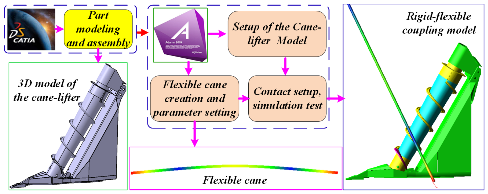
Before establishing the RFC simulation model, the crop divider was simplified based on previous virtual-prototype and RFC simulation studies of sugarcane lifting mechanisms. In the simplified model, key components directly involved in sugarcane lifting and contact–namely the lifting spiral, divider toe, and support frame—were retained, while small bolts, filets, and noncontact auxiliary parts were removed to improve computational efficiency. Similar simplification strategies have been applied in virtual–prototype simulations and parameter optimization studies of sugarcane lifters [13], as well as in RFC simulations of lodged sugarcane–crop divider interactions [9]. Specifically, Wang et al. [9] simplified the crop divider by retaining the lifting scrolls, crop divider toes, and bracket, established the model in CATIA V5R20, exported it in .stp format, and imported it into ADAMS 2019 for dynamic simulation (Figure 5).
The flexible representation of sugarcane stalks was informed by experimental studies on stalk mechanical properties. For example, Ma et al. [16] measured key physical and mechanical parameters of sugarcane stalks—including moisture content, elastic modulus, torsional characteristics, compression load, and compressive strength–providing a theoretical basis for modeling and mechanized harvesting analysis. In this study, the basal end of the flexible sugarcane stalk was constrained by a spherical joint to represent stalk–base/stool anchorage in soil, restricting free translation of the basal point while allowing rotation during lodged–stalk bending. Soil deformation, below-ground stool damage, cane leaves, and random ground unevenness were not explicitly modeled; thus, the simulation primarily focused on the mechanical interaction between the lodged sugarcane stalk and the crop divider during the lifting process.
Contact between the sugarcane stalk and the steel lifter was modeled using an impact-contact formulation combined with Coulomb friction. The normal contact parameters were set as follows: stiffness = 2855 N mm−1, force exponent = 1.1, maximum damping = 0.57 N/(m/s), and penetration depth = 0.10 mm. The static and dynamic friction coefficients were 0.30 and 0.25, respectively, with stiction and friction transition velocities of 0.10 mm/s and 10.00 mm/s. These contact and friction parameters were primarily adopted from the RFC simulation of lodged sugarcane–crop divider interaction reported by Wang et al. [9], which employed the same ADAMS-based contact settings. The sugarcane stalk geometry, density, and elastic modulus were determined based on mechanical-property tests of GuiTang 46 ratoon cane [16]. Previous virtual-prototype studies of sugarcane lifters [13,15] and the sugarcane lifting–cutting system study by Wang et al. [7] were further used as methodological references for virtual-prototype modeling, lifting simulations, and operating-parameter selection. Together with the material properties listed in Table 1, these parameters define the contact and boundary conditions necessary for reproducing the simulation.
The ground and global coordinate system were fixed. The SSL advanced at 0.55 m/s (≈2 km/h), and the lifting drum rotated at 160 r/min, with a roller inclination angle of 60°. The initial lodging postures were defined by LA θ = 10°, 20°, and 30°, and SDA ξ = 30°, 90°, and 150°. The selected forward speed represents a low-speed operating condition commonly used for lodged sugarcane lifting simulations and field operations in South China [7,9,13]. In comparison, studies on commercial sugarcane harvesters in Brazil have evaluated higher forward speeds, ranging from 4.0–5.5 km/h [36] and 3.0–7.0 km/h [37]. Therefore, the applicability of the optimized SSL under higher-speed harvesting conditions is discussed as a limitation rather than being directly inferred from the present low-speed validation.

2.4. Experimental Design

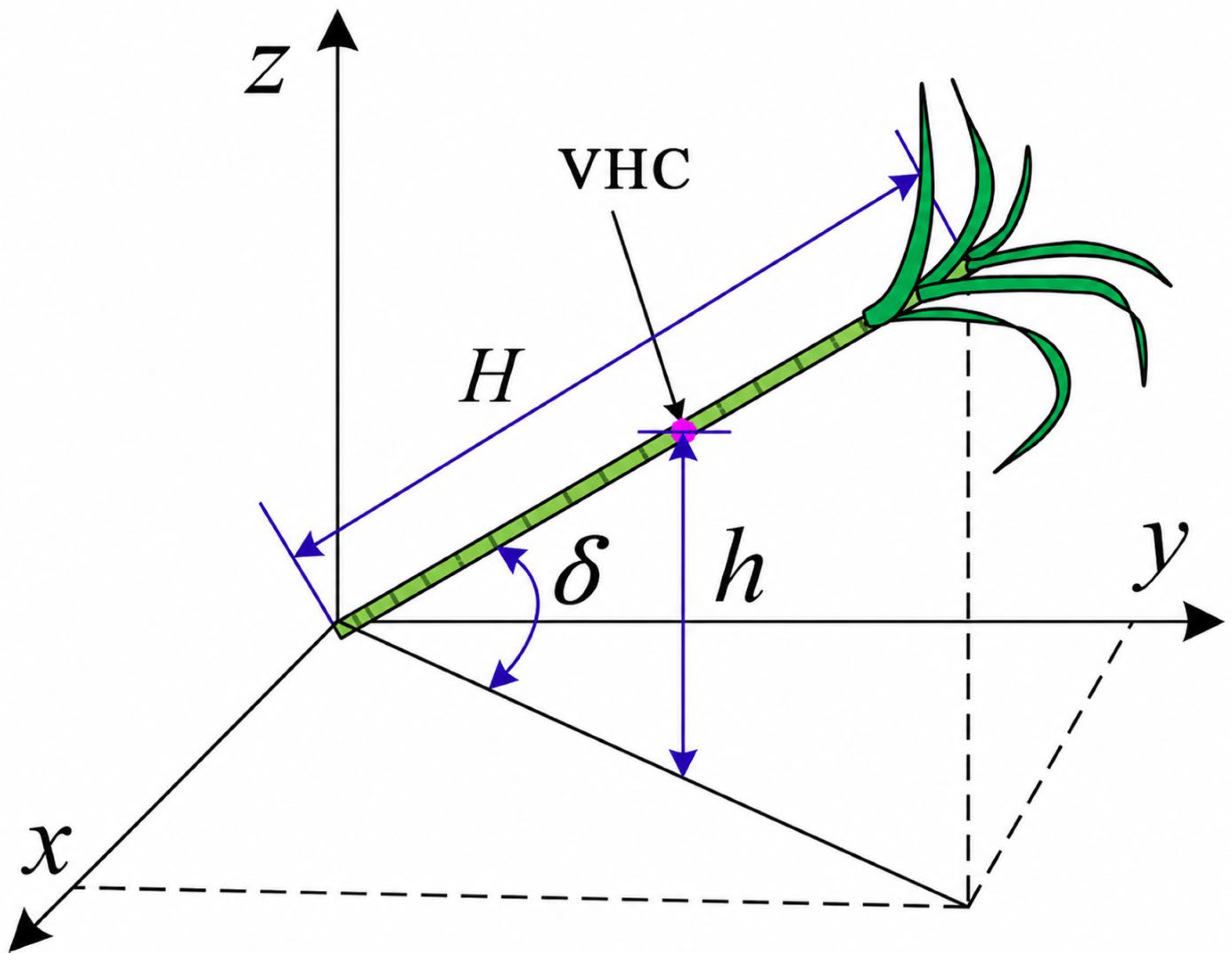
To investigate the limitations of the spiral sugarcane lifter, severely lodged sugarcane (LA = 10°) was selected as the baseline research object. Specifically, the more challenging side-forward lodging condition was chosen, and a forward speed of 0.55 m/s (≈2 km/h) was applied for the simulation study of the spiral lifter [18,19]. Based on existing research findings and practical engineering requirements, the time-history profile of the VHC during lifting, as well as its maximum value, were adopted as evaluation criteria, since lifting height is directly related to stalk posture prior to base cutting and has been widely used in sugarcane lifter and crop-divider performance assessments [7,13,18,19]. The selection and schematic representation of the sugarcane VHC are shown in Figure 6. In this study, the sugarcane stalk is assumed to be homogeneous, such that its centroid coincides with its geometric center. The calculation is as follows:
h = H 2 s i n δ
where h is the VHC of the sugarcane stalk (mm); and H is the effective total stalk length (mm).

3. Defect Analysis and Parameter Optimization of the SSL

3.1. Defect Analysis of the Original SSL

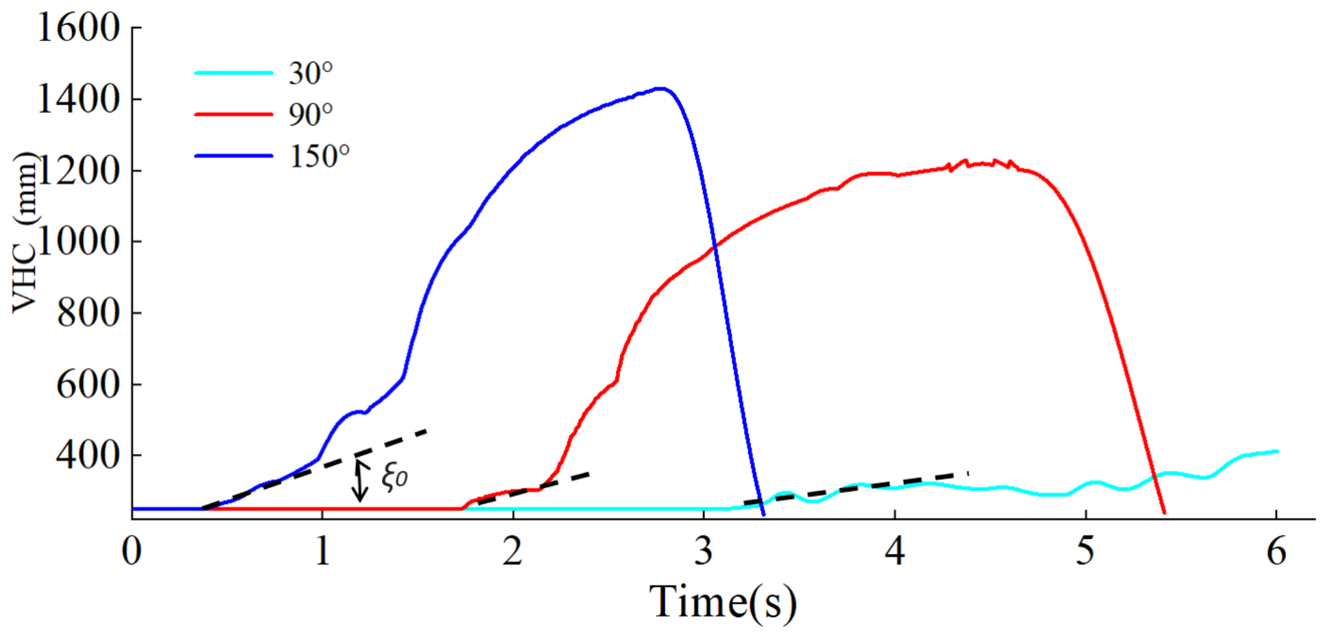
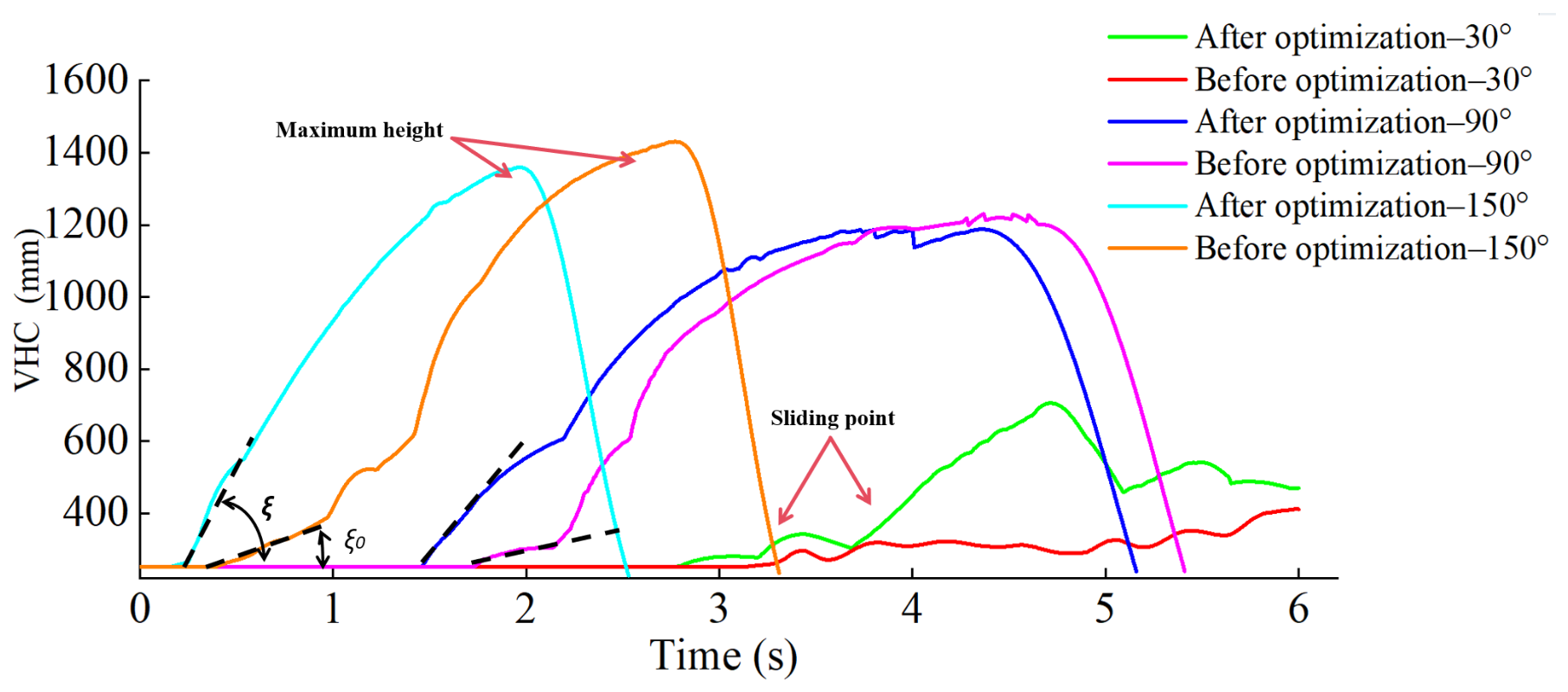
When LA was 10°, the variation curves of the VHC during the lifting of the LSC by the original SSL under different lodging forms (SDA = 30°, 90°, and 150°) are shown in Figure 7. In the figure, the dashed line represents the lifting speed of the VHC. As observed, for side-backward lodging (SDA = 150°) and side lodging (SDA = 90°), the VHC was lifted slowly after an initial period of interaction between the SSL and the sugarcane. Once the VHC reached a certain height, it exhibited small fluctuations; subsequently, as the SSL continued to advance, the sugarcane reached its maximum height, detached from the SSL, and then fell to the lowest point.
Although sugarcane with backward and side lodging could be lifted smoothly by the SSL, the initial lifting speed upon contact was relatively low, resulting in a longer overall lifting duration. In contrast, for side-forward lodging (SDA = 30°), the VHC curve fluctuated continuously during interaction between the SSL and the LSC, and the overall change in VHC was minimal. This indicates that the SSL was unable to lift the LSC smoothly. The analysis suggests that this limitation was primarily caused by suboptimal structural parameters of components such as the lifter shoe, spiral guide, and lifter drum.
Based on the aforementioned problem analysis, together with the structure of the original lifter drum, field test feedback, and mechanism-based analysis, the existing problems of the original SSL and the corresponding redesign schemes were summarized. The drawbacks were mainly concentrated in the lifter shoe, spiral guide, lifter drum, and helical blades of the lifter drum. To clarify the meaning of “optimization” in this study, the design variables were defined as lifter shoe length, straight-section roller length, lower and upper roller radii, pitch, roller inclination angle, and rotational speed. The objective was to increase stable VHC and reduce slippage under severe LSC conditions while satisfying the geometric constraints of the medium-sized harvester and maintaining compatibility with the original feeding inlet. The causes of the problems and the proposed redesign schemes are shown in Table 2.

3.2. Optimization of Key Parameters

3.2.1. Optimization of Pitch and Roller Diameter

Theoretical research on the SSL has consistently been challenging, and many optimization designs are still based on engineering experience [10,11]. During the interaction between LSC and the lifter, the sugarcane does not rotate with the spiral blade but primarily moves axially along the lifter drum. To determine the factors influencing pitch and roller diameter, this study simplifies the interaction between the SSL and LSC as the transport of a flexible stalk by an open–type screw conveyor. This simplification facilitates transparent parameter selection but does not account for all soil–stalk and stalk–population interactions.
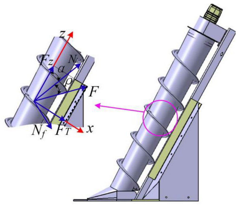
From the force analysis in Figure 8, we obtain
F Z = F cos ( α + ρ ) F T = F sin ( α + ρ ) α = arctan P 2 π r ρ = arctan μ
To enable the sugarcane to move along the axis of the lifter, the difference between the normal thrust and the frictional resistance in the axial direction must be greater than zero, i.e.,
N cos α > N f cos α N f = μ N = μ tan ρ
That is
N cos α > μ tan ρ cos α
cos α > tan ρ
Thus, we obtain
α < π 2 ρ
To enable the sugarcane to move upward along the lifter drum, its helix angle must satisfy the condition of Equation (27). Furthermore, to ensure axial movement, the resultant force in the axial direction must be greater than zero. That is:
F Z = F cos ( α + ρ ) > 0
According to Equation (28), the helix angle α is positively correlated with the circumferential force and negatively correlated with the axial force. An increase in circumferential force reduces the balance force acting on the LSC, whereas an increase in axial force improves the lifting efficiency of the LSC. Therefore, to determine the maximum allowable pitch value, one of the conditions that must be satisfied is as follows:
P max π r tan π 2 ρ = π r tan ρ
Furthermore, another key condition for determining the maximum allowable pitch is that the circumferential velocity at each point should not exceed the axial velocity, while the rising motion of the LSC should retain an appropriate axial velocity component. Kinematic analysis indicates that the axial and circumferential velocities are both influenced by the pitch. Therefore, in addition to ensuring a sufficiently large upward axial velocity, the circumferential velocity at each point on the helical blade must also remain less than or equal to the axial velocity. Thus, it can be obtained that
P n 60 1 f P 2 π r P 2 π r 2 + 1 P n 60 P 2 π r + f P 2 π r 2 + 1
f + P 2 π r 1 f P 2 π r
By rearranging, we obtain
P 2 π r ( 1 f ) 1 + f
Analysis of existing literature indicates that drum diameter selection often relies on engineering experience and references to existing harvesters. To improve the rationality of the optimized SSL, the lower-end radius of the lifter drum was determined based on the original SSL, as follows:
R 1 = r 1 + r 2 2
where R1 is the outer radius of the lower end of the optimized SSL drum; r1 is the lower-end radius of the SSL drum before optimization, with a dimension of 75 mm; and r2 is the outer radius of the upper end of the SSL drum before optimization, with a dimension of 100 mm. The calculation result is 87.5 mm. After rounding, the outer radius of the lower end of the optimized SSL drum is determined to be 90 mm. The outer radius of the upper end is determined by referencing the corresponding ratio of the upper and lower radii of the original SSL drum, i.e.,
R 2 = R 1 r 2 r 1
Substitution into the calculation yields an outer radius of 120 mm for the upper end of the optimized SSL drum. Using the lower-end dimensions as a reference for pitch selection, and based on kinematic analysis, Equations (29) and (32), material interaction characteristics, and previous studies [15,16], the optimized SSL pitch is determined to be 250 mm.

3.2.2. Optimization of the Straight-Section Roller Parameter

Simulation results showed that the SSL required a relatively long time to initiate the lifting of LSC, and the lifting speed was low; in some cases, the LSC could not be lifted at all. Based on theoretical analysis and relevant experience, a straight cylinder of appropriate length was added to the lower end of the SSL drum. The purpose was to ensure that, when severely lodged LSC came into contact with the lower end of the drum, they were first uniformly lifted to a certain height by the spiral on the straight cylinder and then entered the accelerated lifting stage along the axial direction of the conical drum.
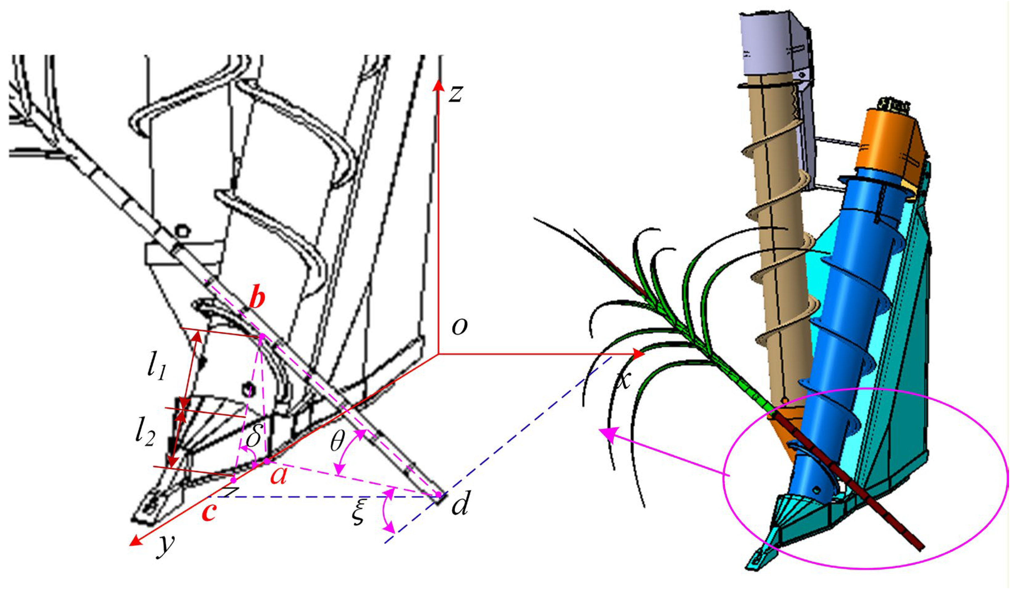
The determination of the straight-cylinder length should consider not only the lodging characteristics and forms of the LSC, but also the structural configuration of the lower end of the SSL. To this end, a schematic diagram of the lower–end structure of the SSL was established, as shown in Figure 9. Assuming that the contact point between the LSC and the upper end of the SSL straight cylinder is point b, the length ldc represents the horizontal distance from the crop row to the contact point between the LSC and the SSL in the vertical direction. This length is related to the SSL structure and can be treated as a known parameter. According to the geometric relationship shown in the figure, it can be obtained that
l d c = sin ( 180 ° ξ ) l a d = l a d sin ξ
where
l a b = l a d tan θ
l a b = l b c sin δ
Thus, we obtain
l b c = l d c tan θ sin ξ sin δ = l 1 + l 2
In the equation, l2 represents the effective length of the straight cylinder in mm; l1 represents the length from the lower end of the straight cylinder to the bottom end of the SSL in mm. Restricted by the fixed structure of the SSL, this dimension is a fixed value.
From Equation (38), it can be derived that the length of the straight cylinder is related to the sugarcane lodging angle θ, the angle δ between the SSL drum and the horizontal ground, and the sugarcane side deviation angle ξ. To improve the lifting performance of the SSL on severely LSC and to ensure that the LSC first undergoes uniform lifting by the straight cylinder followed by accelerated lifting by the conical drum, this paper considers the lodging characteristics of LSC. The approach is to first lift the severely LSC to a moderate lodging state before performing accelerated lifting; that is, the sugarcane lodging angle at this moment is set to θ ≥ 30°. Through the analysis in the subsequent text, the angle δ between the SSL and the ground is selected to be 60°. According to the structural characteristics of medium-sized harvesters, the horizontal distance ldc from the crop row to the vertical line passing through the contact point between the sugarcane and the SSL is approximately 450 mm. Through the calculation of the above spatial relationship, the length of the straight cylinder is approximately 180 mm.

3.2.3. Selection of Roller Inclination Angle and Rotational Speed

Selection of the Roller Inclination Angle
The angle between the SSL drum and the ground is also a significant factor affecting SSL lifting performance. A smaller angle increases the lifting distance of the LSC, thereby requiring a longer time to achieve the desired lifting height. Conversely, a larger angle increases the difficulty of lifting the LSC and raises the likelihood of LSC slipping during the lifting process. Experimental studies and analyses by Song et al. [11], and others indicate that an angle of 60° between the SSL drum and the horizontal ground provides relatively favorable lifting performance for the LSC. Therefore, based on existing studies, this paper adopts an angle of 60° between the SSL drum and the horizontal ground.
Selection of the Roller Rotational Speed
Previous studies indicate that, in the process of material transport by a helical shaft, the rotational speed should be determined based on the balance between the material’s gravitational force and the centrifugal force generated during shaft rotation. To ensure smooth material conveying, it is necessary to maintain equilibrium between the material’s own gravity and the inertial centrifugal force induced by the rotation of the helical shaft [14], i.e.,
m ω 2 r m g
Therefore,
ω max = 2 π n m a x 60
we obtain
n max 30 π g r
Previous SSL studies indicate that the scroll rotational speed and installation angle significantly affect lifting performance, and that parameter selection should be based on the actual interaction characteristics between the stalk lifter and the crop [17,18]. Based on the kinematic analysis of the interaction between the LSC and the SSL drum presented in this paper, an excessively high rotational speed may cause the LSC to be thrown away from the spiral surface, thereby reducing lifting quality while increasing stalk breakage and power consumption. In contrast, an appropriate rotational speed can improve lifting performance. Considering field experience and previous research findings [18], this study selects a rotational speed of 160 r/min for the SSL. The selected forward speed of 0.55 m/s is consistent with low-speed harvesting of severely lodged cane in hilly areas; however, the higher operating speeds of 3.0–7.0 km/h reported in Brazilian commercial studies [36,37] would increase biomass flow and contact impact and should therefore be validated separately.

4. Results and Analysis

4.1. Three-Dimensional Models of the Sugarcane Lifter Before and After Optimization

Based on the above analysis, structural optimization was performed on the SSL. The structures of the SSL before and after optimization are shown in Figure 10, where the three-dimensional structural model of the pre-optimized SSL is shown on the left. A comparison of the key parameters before and after optimization is presented in Table 3.
In addition to optimizing the key parameters discussed above, the lifter shoe, frame, and sidewall components of the feeding inlet were also improved based on field feedback. The lifter shoe and spiral guide vanes are the first components to contact severely lodged LSC, directly determining whether the sugarcane can be successfully lifted. To further improve the lifting efficiency for severely lodged LSC, the total length d of the lifter shoe was increased, and the angle between the upper cover of the lifter shoe and the ground was reduced. This facilitates the simultaneous gathering and lifting of multiple lodged sugarcane stalks. In addition, the curved–surface lifter shoe was redesigned as a bent sheet-metal structure to increase the contact area and friction between the LSC and the lifter shoe. Considering the diameter of sugarcane stalks, the spiral guide vanes were lengthened and widened to facilitate the lifting of highly lodged LSC. The clearance between the lifter drum and the lifter shoe was increased to assist in discharging loose soil and prevent blockage, thereby ensuring smoother rotation of the drum. Regarding the sugarcane separating drum, the original conical drum was replaced with a straight drum, which reduces manufacturing cost while maintaining separation effectiveness.

4.2. Simulation Analysis of the Lifting Process After Optimization

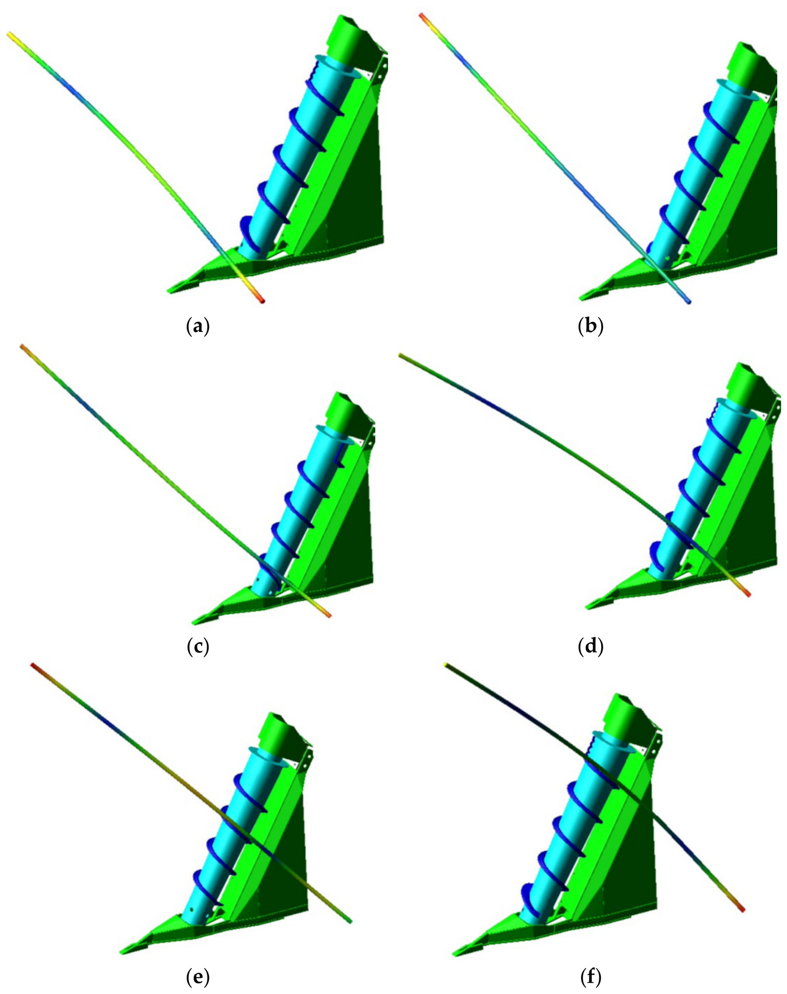
Figure 11 shows the motion diagram of the optimized SSL during the lifting process of the laterally lodged LSC. As the SSL advances, the LSC first comes into contact with the lifter shoe and is gently lifted, gradually moving onto the spiral guide vane. With the forward motion of the machine and the rotational action of the SSL drum, the sugarcane gradually and smoothly rises along the spiral tube on the drum. The sugarcane transitions from a laterally lodged state to a laterally forward-lodged state, with the lifting height continuously increasing until it is gradually raised to the highest point, which is consistent with the above analysis. The overall lifting process is relatively smooth. During lifting, due to the RFC between the flexible sugarcane and the rigid lifter, the sugarcane undergoes a certain degree of bending and deformation, resembling the conditions observed in actual field harvesting operations.

4.3. Effect of Lodging Angle on Lifting Performance

To verify the effect of the optimized SSL on the lifting performance of LSC, typical severely lodged LSC (0° < θ ≤ 30°) was selected for comparative tests before and after optimization under identical conditions. The forward speed of the harvester was set to 0.55 m/s (≈2.0 km/h), and the rotational speed of the SSL drum was set to 160 r/min. LA values of 10°, 20°, and 30° were selected. The lodging forms included side–forward lodging, side lodging, and side-backward lodging (SDA values of 30°, 90°, and 150°). The VHC of the LSC was selected as the evaluation indicator, and its lifting trend and maximum value were comparatively analyzed.
Figure 12, Figure 13 and Figure 14 show time-history curves exported from the RFC simulation at fixed time intervals. These curves are used to describe dynamic lifting trajectories rather than independent regression curves. The maximum VHC values extracted from these time histories are summarized in Table 4.
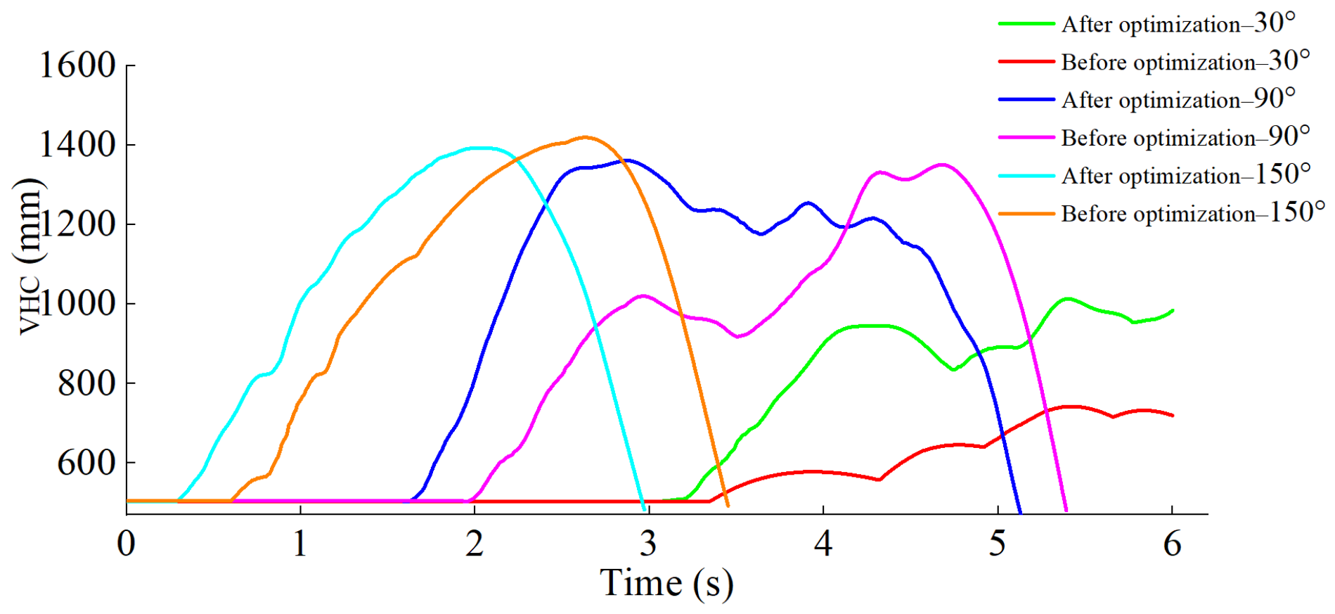
Figure 12 shows the variation in sugarcane VHC during operation of the pre-optimization and post-optimization lifters when the LA is 10° and the SDAs are 30°, 90°, and 150°, respectively. As shown in Figure 12, when the SDA of the sugarcane is the same, the optimized SSL contacts the sugarcane first, which is attributed to the improved design of the lifter shoe.
When the SDA is 150°, the maximum VHC of the pre–optimized lifter is slightly higher overall than that of the optimized lifter. Specifically, when the LA is 10°, 20°, and 30°, the reductions in the maximum lifting height of the optimized SSL relative to the pre–optimized one are 4.98%, 1.85%, and 2.16%, respectively. The paired comparison of the three SDA = 150° cases did not show a statistically significant improvement. This result indicates that the optimized structure does not universally increase the maximum VHC in every posture, although it improves early lifting continuity and reduces slippage in the critical side-forward lodging condition.
When the SDA is 30°, the optimized SSL shows a clear advantage over the pre-optimized version. When the LA is 10°, 20°, and 30°, the increases in the maximum VHC are 71.11%, 36.44%, and 13.54%, respectively, with an average increase of 40.36%. A paired comparison of the three SDA = 30° cases indicated a significant improvement in maximum VHC after optimization. Therefore, the optimized SSL is particularly beneficial for side-forward lodging under the tested low-speed, severe-lodging conditions.
In Figure 12, the slope of the dashed line relative to the horizontal axis can indirectly represent the rate of change in the sugarcane VHC during the lifting process. It can be clearly observed that, under the same LSC posture conditions, the optimized SSL exhibits a higher rate of change and is able to lift the LSC quickly and smoothly. When the SDA is 30°, a low point appears in the curve before the sugarcane is lifted to the highest point; this is caused by slippage during the lifting process. However, the sugarcane is successfully lifted after two slips. The occurrence of slippage points during the lifting process is common in experiments [8]. The optimized SSL is able to lift the sugarcane again quickly and smoothly after slipping, which also indicates that the optimized sugarcane lifter has better lifting performance than the pre–optimized lifter.
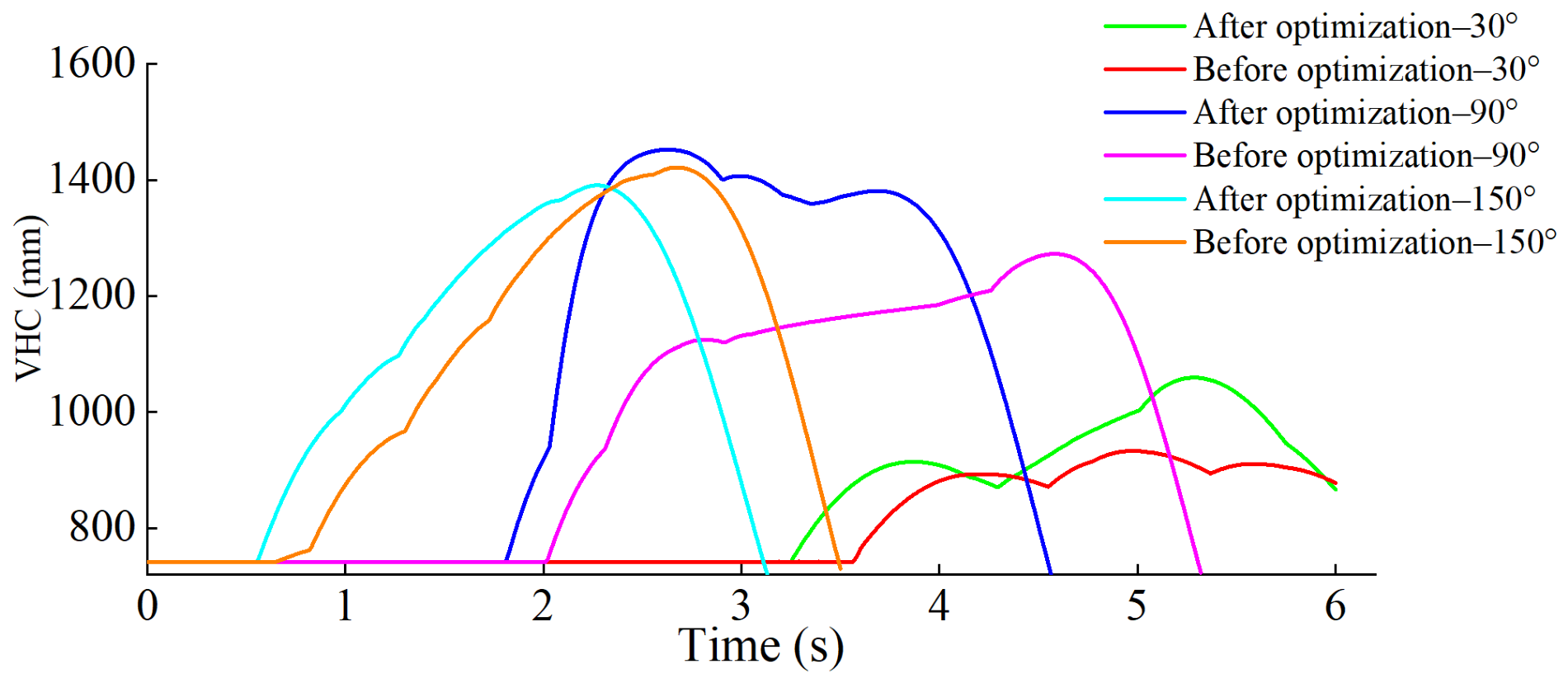
Figure 13 shows the variation in VHC during the lifting process when the sugarcane LA is 20°. It can be observed from Figure 13 that, compared with the case where the LA is 10°, the variation in VHC during lifting is relatively stable when the SDA is 150° or 90°. In particular, when the SDA is 90°, the sugarcane is lifted to the maximum height at a relatively uniform rate, and the optimized lifter raises the VHC to the first peak earlier. However, when the SDA is 150°, the pre–optimized lifter exhibits a slow increase in height during the initial lifting stage; in comparison, the VHC of the optimized lifter increases more uniformly.
When the SDA is 90° (i.e., side lodging), the maximum lifting height of the optimized SSL gradually increases as the LA increases. When the LA is 30°, the VHC reaches 1452.37 mm; at this point, the maximum VHC is 14.13% higher than that of the pre-optimized SSL. The paired comparison of the three SDA = 90° cases did not show a significant overall difference (mean difference = 49.19 mm), suggesting that the main benefit of the optimized structure in this posture lies in lifting stability rather than in a consistent increase in maximum VHC.
The above analysis indicates that the optimized SSL improves lifting performance mainly under the tested side-forward lodging condition and maintains acceptable lifting stability under side and side-backward lodging conditions.

4.4. Comparative Analysis of the Maximum VHC

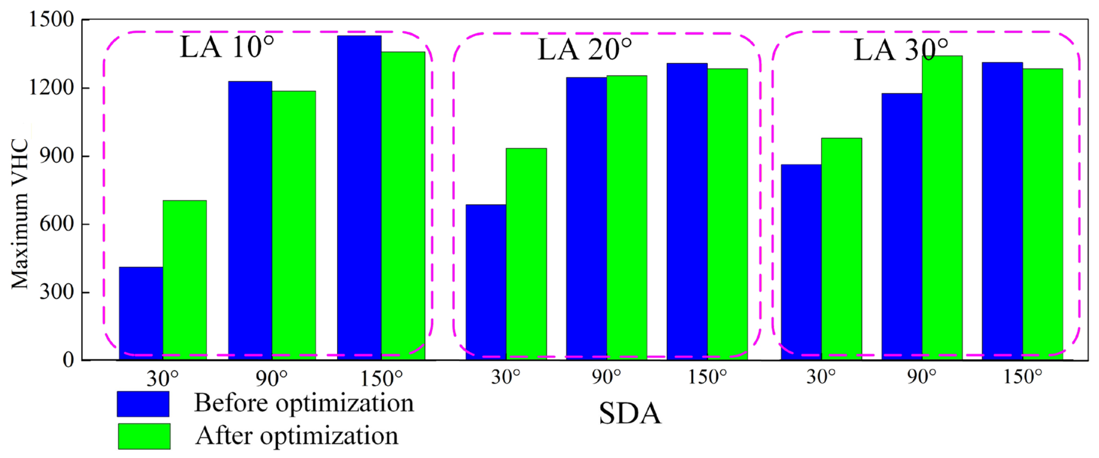
The maximum lifting heights of the sugarcane lifter before and after optimization under different experimental conditions are shown in Figure 15 and Table 4. As shown in Figure 15, green rectangles indicate the maximum sugarcane lifting height of the optimized SSL, whereas blue rectangles correspond to the maximum VHC of the pre–optimized SSL.
When the SDA is 150°, the maximum VHC of the pre–optimized lifter is overall slightly higher than that of the optimized lifter. Specifically, when the LA is 10°, 20°, and 30°, the reductions in the maximum lifting height of the optimized SSL relative to the pre–optimized one are 4.98%, 1.85%, and 2.16%, respectively. This difference is attributed to the adjustment of the angle between the SSL drum and the horizontal ground. Although the maximum reduction in lifting height after optimization is 4.98%, the optimized SSL can still lift the sugarcane rapidly under all conditions, thereby meeting the performance requirements and demonstrating superior lifting stability.
When the SDA is 90° (i.e., lateral lodging), the maximum lifting height of the optimized SSL gradually increases as the LA increases. When the LA is 30°, the VHC reaches 1452.37 mm; at this point, the maximum sugarcane VHC is 14.13% higher than that of the pre–optimized SSL.
When the SDA is 30°, the optimized SSL shows a clear advantage over the pre–optimized version. When the LA is 10°, 20°, and 30°, the increases in the maximum sugarcane VHC of the optimized lifter are 71.11%, 36.44%, and 13.54%, respectively, with an average increase of 40.36%. When the sugarcane is in a lateral-forward lodging state, the optimized SSL exhibits good performance, with a minimum VHC of 705.62 mm, representing a substantial improvement over the pre-optimized lifter.

4.5. Field Validation Tests

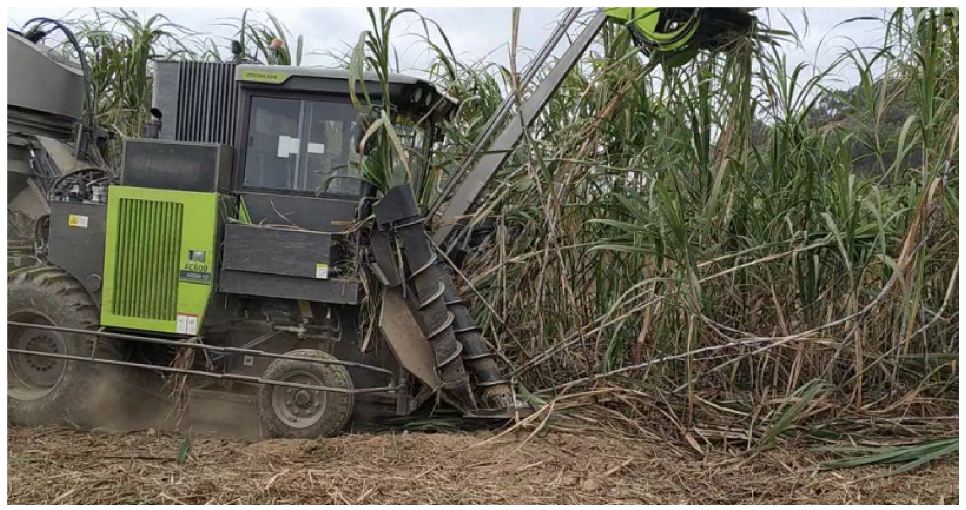
To verify the accuracy of the simulation model and the operational performance of the optimized SSL, field trials of the sugarcane harvester equipped with the optimized SSL were conducted in Daxu Village, Xingbin District, Laibin City, Guangxi Zhuang Autonomous Region, China, during the 2020 and 2021 harvesting seasons (Figure 16). The test crop was GuiTang 46 ratoon cane, with a planting density of 8.5 stalks/m, an average effective stalk height of 2859 mm, and an average basal stalk diameter of 30.55 mm; these physical parameters are consistent with the material-property measurements reported by Ma et al. [16]. The crop was mature and severely lodged, and the tests were conducted in a typical local sugarcane field under trafficable soil-surface conditions. During the experiment, the midpoint of each sugarcane stalk was marked with label paper. A measuring ruler was placed vertically on the ground beside the harvester, and a camera recorded the height of the projected midpoint label on the ruler at different moments. The harvester forward speed was 0.55 m/s (≈2 km/h). Verification was conducted for the maximum lifting height of the stalk midpoint under LA of approximately 20° and SDA values of approximately 30°, 90°, and 150°. Each SDA condition was repeated three times, and the average field value was compared with the corresponding maximum VHC from the simulation. The results are shown in Table 5.
Slippage of the sugarcane stalks was observed during the field experiment, especially when the SDA was 30°, which was consistent with the trajectory analysis in the simulation. The simulation-field error was calculated as Error = |Hsimulation − Hfield|/Hfield × 100%, where Hsimulation is the maximum VHC obtained from the RFC simulation and Hfield is the corresponding average field measurement. According to Table 5, the maximum error was 6.39%, the minimum error was 3.76%, and the mean absolute error was 5.37%. Similar coupled simulation methods have also shown good consistency between numerical analysis and experimental results in other agricultural feeding devices [32]. Therefore, the RFC model can be considered effective for comparing the optimized SSL under the tested low-speed severe-lodging conditions. The remaining errors may be attributed to machine vibration, uneven ground, variation in stalk stiffness, operator control, and field soil variability.

5. Conclusions and Discussion

Based on the RFC simulation model established between the SSL and sugarcane, this study conducted a mechanism–guided redesign and experimental evaluation of key SSL parameters. The simulation results showed that pitch, roller diameter, roller inclination angle, and lifter shoe length are important factors affecting lifting performance. Under the tested low-speed severe-lodging conditions, the relative lodging posture between the LSC and the lifter strongly affected the lifting response. The most significant improvement occurred when the SDA was 30°: the average maximum VHC increased by 40.36%, and the paired comparison of the three corresponding simulation cases indicated a significant increase. In contrast, the improvements were not statistically significant for SDA = 90° or 150°, indicating that the optimized SSL mainly improves the difficult side-forward lodging condition rather than universally increasing the maximum VHC under all postures.
Field validation further showed that, at an LA of approximately 20° and SDA values of approximately 30°, 90°, and 150° at 0.55 m/s, the average absolute error between the simulation and field measurements was 5.37%. This supports the use of the RFC model as a comparative design tool under the tested working conditions. This study provides a reference for the parameter redesign of medium–sized SSLs used in lodged sugarcane fields and expands the knowledge base of crop–machine coupled simulation for sugarcane harvesting equipment.
This study establishes a theoretical model and an optimization method for the key operating parameters of SSL, and verifies their feasibility. The research findings can enrich the database of relevant studies. However, the present work still has the following limitations, which also indicate the main directions for future research. The flexible sugarcane stalk in the RFC model is an idealized representation of a single stalk with simplified material properties and a constrained basal end; it does not fully represent natural variability in stalk stiffness, leaf mass, cracked stalk surfaces, below-ground stool deformation, or soil–root interaction. The model was calibrated mainly under low–speed, single-stalk, severe-lodging conditions and does not yet sufficiently account for multi–stalk entanglement, leaf and trash flow, mineral and vegetable impurities, ground unevenness, soil deformation, soil compaction, or high–throughput harvesting scenarios [38,39]. Field validation was also limited in sample size and operating-condition coverage. Therefore, the proposed design improvements should be interpreted within the tested conditions. Future research should include larger field datasets, high-speed operation, multiple biomass–flow levels, impurity and ratoon–damage KPIs, and multi–stalk/soil interaction modeling to improve the model’s applicability and commercial relevance.

Author Contributions

Conceptualization, Q.W.; methodology, Q.W.; software, B.Z.; validation, B.Z.; formal analysis, C.J.; investigation, C.J.; resources, Q.W.; data curation, C.J.; writing—original draft preparation, Q.W.; writing—review and editing, J.W.; visualization, J.W.; supervision, K.Y.; project administration, Q.W.; funding acquisition, Q.W. All authors have read and agreed to the published version of the manuscript.

Funding

This study was funded by the Key Project of the Department of Education of Anhui Province (Grant No. 2024AH050307), the National College Student Innovation Training Program Project (Grant No. 202510879054), the University-level Interdisciplinary Discipline (Grant No. XK-XJJC002), the Natural Science Research Project of Anhui Provincial Universities (Grant No. 2023AH051856), the Anhui Science and Technology University Talent Introduction Project (Grant No. JXYJ202201), and the 2025 New Era Education Quality Engineering Project, “Case Library for Professional Degree Teaching in Mechanical Engineering (Advanced Agricultural Machinery)” (Grant No. 2025Xzyxwjxalk001).

Institutional Review Board Statement

Not applicable.

Informed Consent Statement

Not applicable.

Data Availability Statement

The data presented in this study are available on request from the corresponding author.

Conflicts of Interest

The authors declare no conflicts of interest.

Abbreviations

The following abbreviations are used in this manuscript:
SSLSpiral Sugarcane Lifter
LSCLodged Sugarcane
VHCVertical Height of Centroid
RFCRigid–Flexible Coupling
SDASide Deflection Angle
LALodging Angle

References

  1. Siva, M.; Sendhilvel, V.; Thangeswari, S.; Malathi, P.; Karthikeyan, G.; Arun Kumar, R.; Harish, S.; Sassikumar, D.; Baskaran, V. Etiology and histopathological insights of twisted top disease: A re-emerging threat to sugarcane cultivation. Physiol. Mol. Plant Pathol. 2025, 139, 102747. [Google Scholar] [CrossRef]
  2. Mahadea-Nemdharry, R.; Doorga, J.R.S.; Busawon, K.; Seeruttun, S. Enhancing sugarcane field management in a tropical island: A comparative analysis of mapping gaps in sugarcane fields using drone and satellite imageries. Remote Sens. Appl. Soc. Environ. 2025, 38, 101570. [Google Scholar] [CrossRef]
  3. Hu, J.; Ma, S.; Wang, F.; Xing, H.; Bai, J.; Wei, Y.; Ding, Z. Design and Development of Sugarcane Top Chopper and its Field Performance. Sugar Tech 2021, 23, 1192–1198. [Google Scholar] [CrossRef]
  4. Wu, T.; Liang, X.-L.; Liu, Q.-T.; Zhang, Z.-X.; Xu, H.; Huang, J.-B.; Li, J.-X.; Zou, X.-P. Chopper Sugarcane Combine Harvester with Middle-Mounted Primary Extractor. Sugar Tech 2020, 22, 589–595. [Google Scholar] [CrossRef]
  5. Christina, M.; Heuclin, B.; Pilloni, R.; Mellin, M.; Barau, L.; Hoarau, J.-Y.; Dumont, T. Climate, altitude, yield, and varieties drive lodging in sugarcane: A random forest approach to predict risk levels on a tropical island. Eur. J. Agron. 2024, 161, 127381. [Google Scholar] [CrossRef]
  6. Bhatt, R.; Singh, J.; Laing, A.M.; Meena, R.S.; Alsanie, W.F.; Gaber, A.; Hossain, A. Potassium and Water-Deficient Conditions Influence the Growth, Yield and Quality of Ratoon Sugarcane (Saccharum officinarum L.) in a Semi-Arid Agroecosystem. Agronomy 2021, 11, 2257. [Google Scholar] [CrossRef]
  7. Wang, Q.; Zhou, G.; Huang, X.; Song, J.; Xie, D.; Chen, L. Experimental Research on the Effect of Sugarcane Stalk Lifting Height on the Cutting Breakage Mechanism Based on the Sugarcane Lifting-Cutting System (SLS). Agriculture 2022, 12, 2078. [Google Scholar] [CrossRef]
  8. Saetear, P.; Saechua, N.; Sereenonchai, K. Sequential Injection System for Analysis of Degree Brix, Orthophosphate and pH in Raw Sugarcane Juice Applicable to Sugar Industry. Molecules 2021, 26, 6484. [Google Scholar] [CrossRef]
  9. Wang, Q.; Zhang, Q.; Zhang, Y.; Zhou, G.; Li, Z.; Chen, L. Lodged Sugarcane/Crop Dividers Interaction: Analysis of Robotic Sugarcane Harvester in Agriculture via a Rigid-Flexible Coupled Simulation Method. Actuators 2022, 11, 23. [Google Scholar] [CrossRef]
  10. Song, C.; Ou, Y.; Liu, Q.; Xie, F. Simulation and experiments of two-stage spiral sugarcane picking-up mechanism. Trans. CSAE 2011, 27, 106–110. (In Chinese) [Google Scholar]
  11. Song, C. Mechanical Analysis and Experimental Research of Spiral Sugarcane Lifter. J. Hunan Agric. Univ. (Nat. Sci.) 2017, 43, 460–463. (In Chinese) [Google Scholar]
  12. Song, C.; Ou, Y. Design and Simulation Analysis of Two-Stage Conical Spiral Sugarcane Lifting Mechanism. J. Agric. Mech. Res. 2019, 41, 137–141+147. (In Chinese) [Google Scholar]
  13. Hu, J.B.; Wang, J.; Hu, Y. Optimization of Parameters for Sugarcane Lifter Based on Simulation of Virtual Prototype. J. Zhejiang Univ. (Agric. Life Sci.) 2014, 40, 111–118. [Google Scholar] [CrossRef]
  14. Zhang, Y.; Ou, Y.; Mou, X. Virtual test on the finger-chain type sugarcane-lifter based on ADAMS. Trans. CSAE 2009, 25, 88–93. (In Chinese) [Google Scholar]
  15. Gao, J.; Ou, Y.; Song, C.; Zhang, Y.; Qing, S. Study on virtual prototype of spiral sugarcane-lifting organ based on physical model. Trans. Chin. Soc. Agric. Mach. 2005, 36, 57–59+70. (In Chinese) [Google Scholar]
  16. Ma, Q.; Li, T.; Xue, W.; Zhao, Y.; Huang, X.; Wang, Q. Experimental Analysis of Mechanical Properties of Sugarcane Stalks. J. Anhui Sci. Technol. Univ. 2024, 38, 51–57. (In Chinese) [Google Scholar] [CrossRef]
  17. Bai, J.; Ma, S.; Wang, F.; Xing, H.; Ding, Z.; Hu, J. Lifting Performance of Crop Dividers with Variable Pitch Spiral Scrolls. Sugar Tech 2022, 24, 1877–1886. [Google Scholar] [CrossRef]
  18. Bai, J.; Ma, S.; Wang, F.; Xing, H.; Ma, J.; Hu, J. Field Test and Evaluation on Crop Dividers of Sugarcane Chopper Harvester. Int. J. Agric. Biol. Eng. 2021, 14, 118–122. [Google Scholar] [CrossRef]
  19. Bai, J.; Ma, S.; Wang, F.; Xing, H.; Ma, J.; Wang, M. Performance of Crop Dividers with Reference to Harvesting Lodged Sugarcane. Sugar Tech 2020, 22, 812–819. [Google Scholar] [CrossRef]
  20. Fagetti, M.; Nazari, M.; Cho, H. Coupled dynamics analysis and adaptive control of rigid-flexible vehicles with model uncertainties. J. Frankl. Inst. 2025, 362, 107774. [Google Scholar] [CrossRef]
  21. Kakavand, M.; Zhu, Z.H. Rigid-flexible coupled dynamics and configuration stability of maneuverable space tether net under impact loads. Acta Astronaut. 2025, 232, 114–131. [Google Scholar] [CrossRef]
  22. Wang, Q.; Bai, Z.; Li, Z.; Xie, D.; Chen, L.; Wang, H. Straw/spring teeth interaction analysis of baler picker in smart agriculture via an ADAMS-DEM coupled simulation method. Machines 2021, 9, 296. [Google Scholar] [CrossRef]
  23. Wang, Q.; Jiang, Y.; Li, L.; Qin, J.; Chen, L. Performance analysis of a spring-tooth drum pickup of straw baler via coupling simulation. Int. J. Agric. Biol. Eng. 2021, 14, 159–165. [Google Scholar] [CrossRef]
  24. Cui, T.; Liu, J.; Zhang, D.; Shi, S. Flexible-Body Simulation of Corn Stalks Based on ANSYS and ADAMS. Trans. Chin. Soc. Agric. Mach. 2012, 43, 112–115. (In Chinese) [Google Scholar]
  25. Pu, M.; Wu, J. Modeling of a Flexible Sugarcane Body Based on ADAMS. J. Syst. Simul. 2009, 21, 1930–1932. (In Chinese) [Google Scholar]
  26. Xie, L.; Wang, J.; Cheng, S.; Zeng, B.; Yang, Z. Optimisation and finite element simulation of the chopping process for chopper sugarcane harvesting. Biosyst. Eng. 2018, 175, 16–26. [Google Scholar] [CrossRef]
  27. Song, C.; Ou, Y.; Liu, Q. Effects of Friction between Spiral Mechanism and Sugarcane on Lifting Performance. J. Hunan Agric. Univ. (Nat. Sci.) 2012, 38, 330–332. (In Chinese) [Google Scholar]
  28. Testa, J.V.P.; Martins, M.B.; Marques Filho, A.C.; Lancas, K.P.; Sobrinho, R.L.; Finatto, T.; Okla, M.K.; AbdElgawad, H. Continuous and Impact Cutting in Mechanized Sugarcane Harvest: Quality, Losses and Impurities. Agriculture 2023, 13, 1329. [Google Scholar] [CrossRef]
  29. Li, B.; Gao, X.; Chen, X.; Liu, Y.; Wang, S.; Dong, Y. Design and Performance Analysis of a Sunflower Cutting Table Based on the Principle of Manual Disk Pick-Up. Agriculture 2024, 14, 446. [Google Scholar] [CrossRef]
  30. Rekem, J.; Janeckova, R.; Otipka, V.; Prokop, A.; Rehak, K.; Zlabek, P. Multi-Body Model of Agricultural Tractor for Vibration Transmission Investigation. Appl. Sci. 2024, 14, 8451. [Google Scholar] [CrossRef]
  31. Hoshyarmanesh, H.; Dastgerdi, H.R.; Ghodsi, M.; Khandan, R.; Zareinia, K. Numerical and experimental vibration analysis of olive tree for optimal mechanized harvesting efficiency and productivity. Comput. Electron. Agric. 2017, 132, 34–48. [Google Scholar] [CrossRef]
  32. Wang, Q.; Xu, D.; Zhu, B.; Jiang, C.; Qiao, Y.; Li, H.; Yang, R. Design and Experimental Research of a CFD-DEM Coupled Pelleted Rice Seeds UAV Hole-Sowing Seed Feeding Device. Agriculture 2026, 16, 561. [Google Scholar] [CrossRef]
  33. Zhou, P.; Wang, Q.; Zhan, M.; Zhu, B.; Yi, K.; Jiang, C.; Wang, J. YOLOv11n-DualPC-Lite: A Lightweight, High-Precision Real-Time Detection Model for Maize Leaf Diseases. Front. Plant Sci. 2026, 17, 1797083. [Google Scholar] [CrossRef] [PubMed]
  34. Bai, J.; Ma, S.; Cheng, C. The Lifting Performance and Experimental Study of a Variable Spiral Spike-Toothed Crop Divider. Agriculture 2024, 14, 916. [Google Scholar] [CrossRef]
  35. Ding, Z.; Ma, S.; Bai, J.; Liang, W.; Zhang, X. Optimization Design and Test of Spike-Toothed Crop Divider. Agriculture 2022, 12, 1692. [Google Scholar] [CrossRef]
  36. Guedes Ramos, C.R.; Pereira Lancas, K.; Albuquerque de Lyra, G.; Millani, T.M. Quality of Sugar Cane Mechanized Harvest as Function of the Forward Speed and Engine Rotation of the Harvester. Energ. Agric. 2014, 29, 87–94. [Google Scholar] [CrossRef]
  37. Martins, M.B.; Marques Filho, A.C.; Drudi, F.S.; Bortolheiro, F.P.A.P.; Vendruscolo, E.P.; Esperancini, M.S.T. Economic Efficiency of Mechanized Harvesting of Sugarcane at Different Operating Speeds. Sugar Tech 2021, 23, 428–432. [Google Scholar] [CrossRef]
  38. Toledo, A.; Silva, R.P.; Furlani, C.E.A. Quality of Cut and Basecutter Blade Configuration for the Mechanized Harvest of Green Sugarcane. Sci. Agric. 2013, 70, 384–389. [Google Scholar] [CrossRef][Green Version]
  39. Delmond, J.G.; Junnyor, W.S.G.; Brito, M.F.; Rossoni, D.F.; Araujo-Junior, C.F.; Severiano, E.C. Which Operation in Mechanized Sugarcane Harvesting Is Most Responsible for Soil Compaction? Geoderma 2024, 448, 116979. [Google Scholar] [CrossRef]
Figure 1. Structural composition of the spiral sugarcane lifter (SSL).
Agriculture 16 01100 g001
Figure 2. Typical lodging postures of sugarcane: (1) side-forward lodging; (2) side lodging; (3) side-backward lodging.
Agriculture 16 01100 g002
Figure 3. Parameter analysis of sugarcane stalk and lifting roller.
Agriculture 16 01100 g003
Figure 4. Positions of sugarcane before and after lifting.
Agriculture 16 01100 g004
Figure 5. Rigid–flexible coupling simulation model.
Agriculture 16 01100 g005
Figure 6. Vertical height of the sugarcane centroid (VHC).
Agriculture 16 01100 g006
Figure 7. Variation in the VHC during lifting using the original SSL.
Agriculture 16 01100 g007
Figure 8. Force analysis of the contact point between the stalk and the spiral blade.
Agriculture 16 01100 g008
Figure 9. Parameter analysis of the straight-section roller length.
Agriculture 16 01100 g009
Figure 10. Comparison of the SSL structures before and after optimization. 1. Lifter boot; 2. Spiral guide plate; 3. Spiral blade; 4. Lifting roller; 5. Divider roller; 6. Bracket.
Agriculture 16 01100 g010
Figure 11. Variation in the lifting posture of sugarcane: (a) t = 1.55 s; (b) t = 1.75 s; (c) t = 2.20 s; (d) t = 2.55 s; (e) t = 3.00 s; (f) t = 3.40 s.
Agriculture 16 01100 g011
Figure 12. VHC variation curves at a lodging angle of 10 degrees.
Agriculture 16 01100 g012
Figure 13. VHC variation curves at a lodging angle of 20 degrees.
Agriculture 16 01100 g013
Figure 14. VHC variation curves at a lodging angle of 30 degrees.
Agriculture 16 01100 g014
Figure 15. Comparison of the maximum VHC before and after optimization.
Agriculture 16 01100 g015
Figure 16. Field tests.
Agriculture 16 01100 g016
Table 1. Simulation model parameters and boundary/contact settings.
ParameterValueUnit
Length of lifting scrolls1300mm
Pitch250mm
Inclination angle of lifting scrolls60°
Sugarcane stalk length3000mm
Sugarcane stalk diameter30mm
Distance between adjacent sugarcane stalks125mm
Poisson’s ratio0.33dimensionless
Elastic modulus1195.44MPa
Density1100kg m−3
Contact stiffness2855N mm−1
Force exponent1.1dimensionless
Maximum damping0.57N s m−1
Penetration depth0.10mm
Static friction coefficient0.30dimensionless
Dynamic friction coefficient0.25dimensionless
Stiction transition velocity0.10mm s−1
Friction transition velocity10.00mm s−1
Table 2. Defects of the original SSL and corresponding causes and optimization schemes.
Component to Be OptimizedDefect DescriptionProposed Optimization
Lifter bootThe boot is too short, causing stalk slippage.Increase boot length; replace the arc surface with a polygonal bent surface to enlarge the contact area.
Spiral guide plateThe plate is too narrow, resulting in slow lifting and frequent slippage.Increase the pitch, overall length, and width of the spiral guide plate.
Conical lifting rollerUnreasonable inclination angle between the roller axis and the ground; small radii at both ends leading to low lifting efficiency.Adjust the inclination angle between the spiral roller and the ground.
Spiral blade on lifting rollerSmall pitch and radius lead to low lifting efficiency.Adjust the pitch of the spiral blade.
Table 3. Comparison of the main parameters of the SSL before and after optimization.
ComponentParameterBefore OptimizationAfter Optimization
Lifting rollerUpper-end radius r2 (mm)100120
Lower-end radius r1 (mm)7590
Total length l (mm)12951300
Inclination angle to horizontal delta (deg)62°60
Pitch P (mm)220250
Straight section length S (mm)/180
Lifter bootTotal length d (mm)260460
Table 4. Change rate of the maximum VHC before and after optimization.
Side Deflection Angle (Deg)Lodging Angle (Deg)Before Optimization (mm)After Optimization (mm)Change Rate (%)
3010412.37705.6271.11%
20742.421012.9836.44%
30932.991059.3313.54%
90101230.331187.91−3.45%
201350.251360.40.75%
301272.531452.3714.13%
150101430.721359.47−4.98%
201418.981392.72−1.85%
301421.681391.02−2.16%
Table 5. Comparison of field test and simulation results.
Side Deflection AngleField Measurement (mm)Simulation Result (mm)Error (%)
30°9561012.985.96
90°13111360.43.76
150°13091392.726.39
Disclaimer/Publisher’s Note: The statements, opinions and data contained in all publications are solely those of the individual author(s) and contributor(s) and not of MDPI and/or the editor(s). MDPI and/or the editor(s) disclaim responsibility for any injury to people or property resulting from any ideas, methods, instructions or products referred to in the content.