Article

Automatic Precision Planting Mechanism of Garlic Seeder

1
School of Agricultural Engineering and Food Science, Shandong University of Technology, Zibo 255000, China
2
Shandong Provincial Key Laboratory of Smart Agricultural Technology and Intelligent Agricultural Machinery Equipment for Field Crops, Zibo 255000, China
3
Ji’nan Huaqing Agricultural Machinery Technology Co., Ltd., Ji’nan 251600, China
*
Author to whom correspondence should be addressed.
Agriculture 2025, 15(8), 849; https://doi.org/10.3390/agriculture15080849
Submission received: 12 March 2025 / Revised: 3 April 2025 / Accepted: 11 April 2025 / Published: 14 April 2025
(This article belongs to the Section Agricultural Technology)

Abstract

:
With the advancement of modern agricultural technology, precision seeding has emerged as a critical approach to enhancing the crop yield and quality. Consequently, a garlic seeder insertion mechanism was developed to improve the accuracy and efficiency of garlic seeding. The single-seed extraction mechanism and the adjustment mechanism for the garlic clove direction were designed based on the appearance dimensions of garlic cloves, enabling precise single-seed selection and orientation. A kinematic model of the insertion planting process was established, with key parameters meticulously described and analyzed, providing theoretical support for determining optimal insertion parameters. A timing sequential control method was adopted to accurately control the periodic motion of the insertion planting mechanism. A speed detection device was utilized to monitor the travel speed of the crawler-type chassis and a rotational speed controller was developed to accurately regulate the rotational speed of the insertion mechanism, ensuring uniform planting distances. Field trials demonstrated that when the preset planting distance was set at 150 mm and sowing operations were conducted at speeds of 0.10 m/s, 0.15 m/s, and 0.20 m/s, the average sowing spacing values were 148 mm, 149 mm, and 151 mm, respectively, the maximum sowing spacing error and root mean square (RMS) error were 30 mm and 7 mm, with an average error of less than 10 mm, and the maximum coefficient of variation was 0.046. The upright rate exceeded 85%, and the missing seeding rate was below 5%. The above results indicated that the designed garlic planting machine insertion mechanism and control method conform to the agronomic requirements for garlic sowing operations.

1. Introduction

Garlic (Allium sativum L.) belongs to the alliaceous family and is a shallow-rooted vegetable crop with medicinal and economic significance [1,2], rendering it an essential component of daily life. China stands as the world’s leading producer and consumer of garlic, boasting the largest planting area globally [3,4]. The traditional artificial seeding method is characterized by a high labor intensity and low seeding efficiency, making it inadequate for meeting the demands of large-scale planting. Consequently, the development of an efficient and precise garlic seeding mechanism is essential for enhancing the productivity of the garlic planting industry.
Studies have shown that the direction of cloves during garlic sowing has an important impact on the emergence time, yield, and visual appearance quality of seedlings [5,6]. The key agronomic requirements for improving the quality and efficiency of garlic planting machines are single-seed planting, upright planting, a consistent planting depth, and a uniform operation [7,8]. Early garlic planting machines could achieve single-seed planting, but lack effective directional devices [9,10], leading to an inability to control the orientation of garlic cloves. This requires manual assistance to guide the garlic cloves into the funnel and furrow soil. Kim Lee Han [11] and others adopted a spoon-type seed extraction method, but it caused damage to the garlic during extraction. Choi Duck Kyu [12] designed an inclined seed extraction and bulb orientation adjustment component for upright planting, which, although effective, still suffered from missing sowing issues. Eom Yong Kyoon [13] invented a garlic planting machine that employed a vibrating long-strip sieve to adjust the garlic cloves’ orientation, which improved the germination rate, but required garlic sorting, thereby increasing costs. Although the mechanical orientation effect was not ideal, its high efficiency and low cost led to widespread use in actual production [14,15]. With the application and development of emerging optical technologies such as machine vision, image recognition, and deep learning, more precise and faster solutions for garlic orientation devices have been provided. Industrial cameras are used to capture images of garlic [16], and the garlic’s orientation is determined through image feature analysis, followed by direction adjustment by a servo motor. Geng et al. [17] designed a groove at the bottom of the funnel, allowing the inverted garlic clove to protrude with the tip of the bulb detected by an infrared sensor. Hou et al. [18] proposed a garlic positioning scheme based on binocular image recognition, using a U-shaped optoelectronic detector and a USB camera to capture images; the processor then identifies the state of the garlic and controls a lever-type correction mechanism to adjust its orientation. Although these technologies improve the directional accuracy, the clarity and completeness of garlic images may be affected by mechanical vibrations and object obstructions, thus reducing the recognition precision. Additionally, the complexity and high costs of these auxiliary processes require further optimization for practical implementation. Recently, capacitive sensing technology has gained widespread application in agriculture due to its non-invasive, rapid, and low-cost advantages, such as in soil moisture measurement [19], crop height and quality detection [20], agricultural machinery operational state monitoring, and real-time parameter monitoring systems [21]. Furthermore, research teams have explored using capacitive sensing technology identifying and adjusting the orientation of garlic, paving the way for more efficient and automated garlic planting systems to meet the growing demands of agricultural production.
In response to issues such as unstable sowing planting distances, difficulty in seed orientation, and low efficiency associated with the garlic sowing equipment, a garlic sowing machine insertion planting mechanism has been designed. A time sequence control method suitable for this insertion planting mechanism has been developed, which enables the precise control of key parameters such as the sequence, speed, and timing of the operational components. This advancement facilitates the automated operation of the garlic sowing machine, providing valuable technical references for the development of intelligent garlic sowing equipment.

2. Materials and Methods

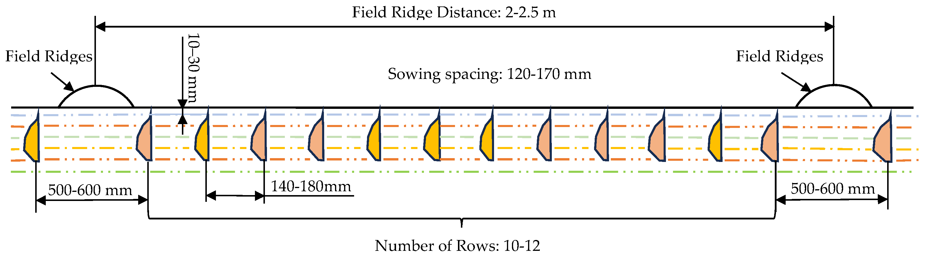
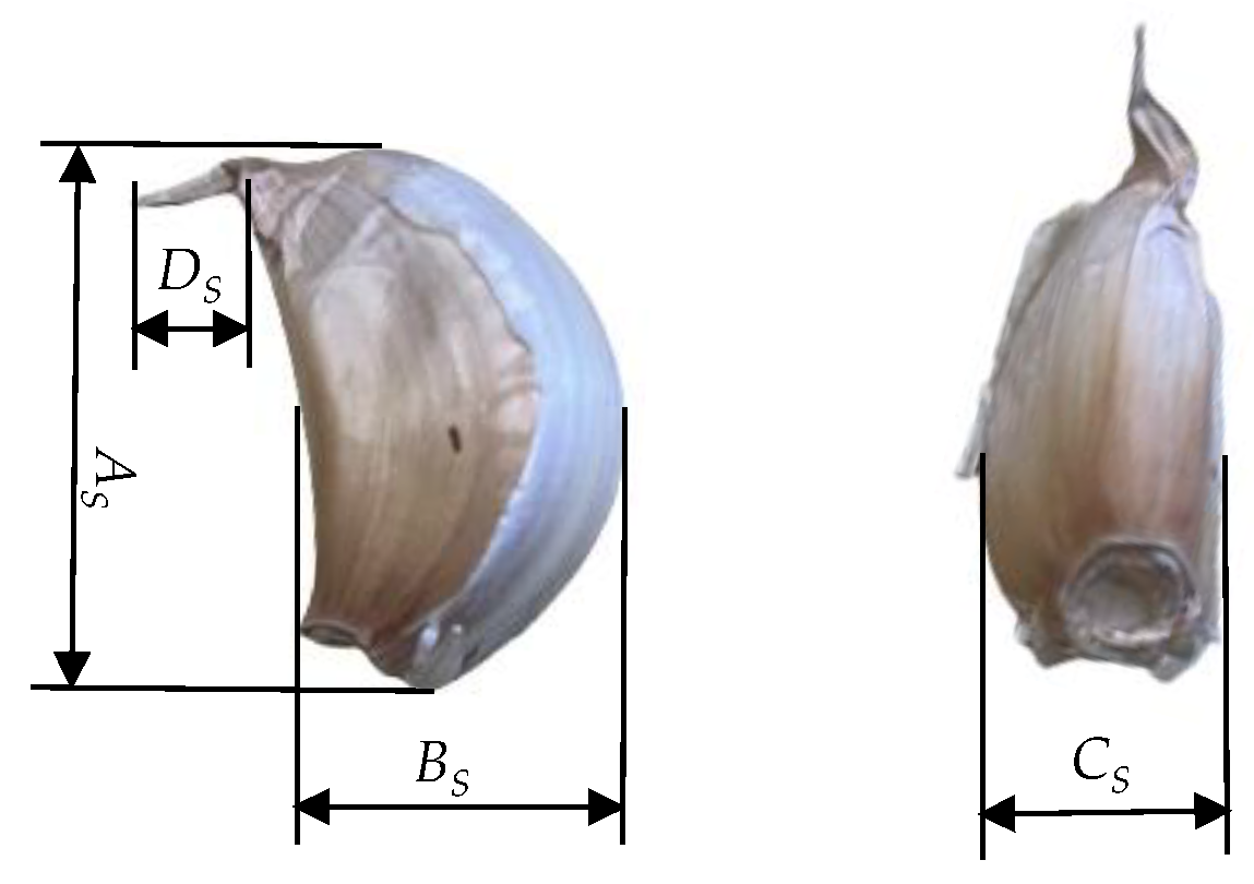
2.1. Agronomic Requirements for Garlic Cultivation

Garlic is a high-value economic crop, and its planting process has strict requirements for sowing accuracy. Strict adherence to agronomic requirements is necessary throughout the entire cultivation process. Effective management of planting density is crucial, as unreasonable planting density can have adverse effects on plant growth and development, ultimately leading to a decrease in yield [22].
In the East China region, the widely adopted planting method is to follow the ridge flat-bed cultivation model. As shown in Figure 1, before sowing, vertical ridges are created with a spacing of 2 to 2.5 m between them. Each plot can accommodate 10–12 rows, with row spacing ranging from 140 to 180 mm and sowing spacing ranging from 120 to 170 mm. The planting density is 120,000 to 150,000 plants per hectare [23,24]. When planting garlic, the bottom (roots) should be planted downwards, and the tip (cloves) should be planted upwards, about 10–30 mm below the soil surface. This orientation is crucial for agricultural practice as it significantly affects the quality of garlic.
The garlic planting process should strictly follow the following principles: uniform row spacing, consistent plant distribution, and standardized planting depth. The planting method is single-seed planting, which means only one seed is placed at each planting position, and the seed should be planted vertically with the bottom (root) facing downwards and the tip (clove) facing upwards. This method helps with rapid germination, simplified management, promotes uniform growth, and facilitates the normal and full development of garlic bulbs, ensuring high yield and excellent quality [25,26].
The ‘Jinxiang’ garlic is the most widely planted type in China. This study focuses on the ‘Jinxiang’ hybrid garlic. Prior to sowing, it is crucial to screen the garlic cloves, selecting those that are plump, undamaged, and crescent-shaped as planting material. Random selection of 100 garlic seeds was made for the measurement of external dimensions and weight, as illustrated in Figure 2.
The statistical analysis of the measured data revealed that the dimensions of garlic seeds conform to a normal distribution, demonstrating a pronounced central tendency. It was noted that the length, width, and thickness dimensions exhibit a positive correlation with seed weight. In contrast, the sprout tip length shows minimal variation, clustering predominantly between 9.0 and 12.0 mm. The mean values for length, width, and thickness were calculated to be 31.6 mm, 15.3 mm, and 18.8 mm, respectively, with an average seed weight of 4.3 g.

2.2. Seeding Experiment Platform and Control System

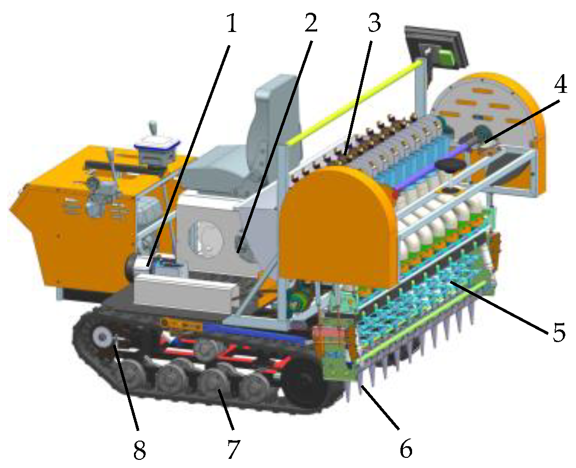
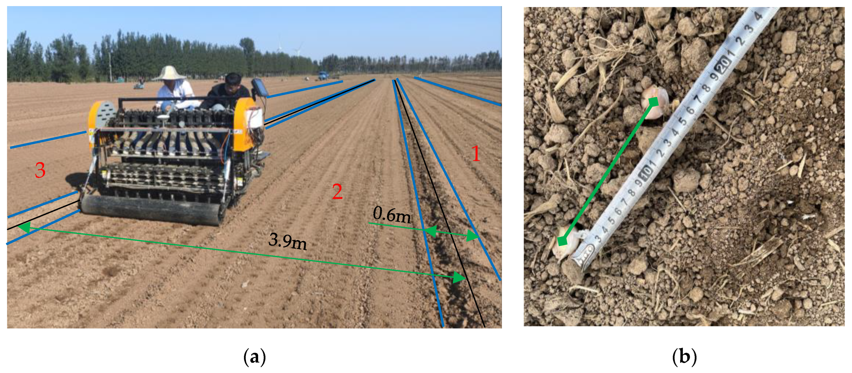
2.2.1. Experiment Platform

The core component of garlic sowing equipment is the insertion planting mechanism, which must be exquisitely designed to seamlessly integrate with the architecture of the testing platform. After all, the predetermined parameters of the platform’s walking system in terms of size, weight, and characteristics directly determine the spatial layout of the inserted planting mechanism and the constraints that must be followed during installation.
Given the excellent maneuverability and adaptability of tracked chassis platforms, their application in the field of agricultural machinery is becoming increasingly widespread [27,28]. The garlic seeder platform in this study consists of three core components: a tracked chassis, an insertable planting mechanism, and a power transmission system. Among them, the insertion planting mechanism is further subdivided into multiple subsystems, including a single-seed extraction mechanism, garlic petal orientation adjustment mechanism, duckbill insertion planting mechanism, cylindrical drive system, and detection and control device. The structural layout of each part is shown in Figure 3. As for the main technical parameters of garlic seeders, they are systematically summarized in Table 1.

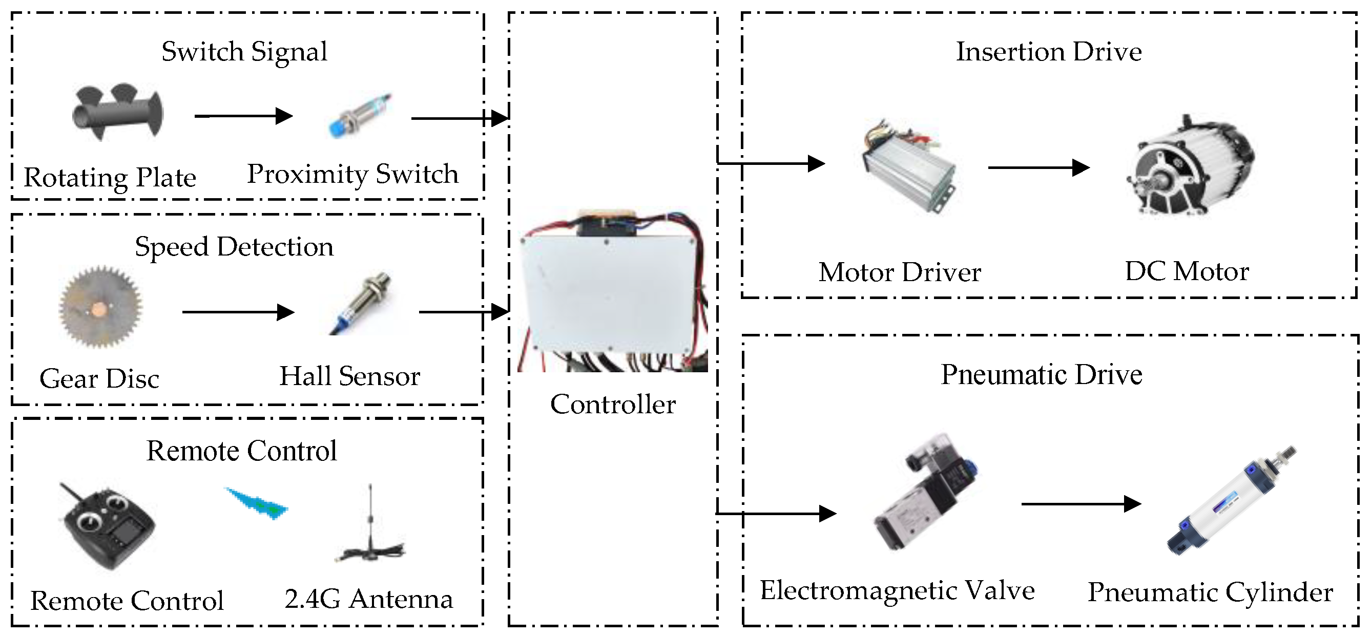
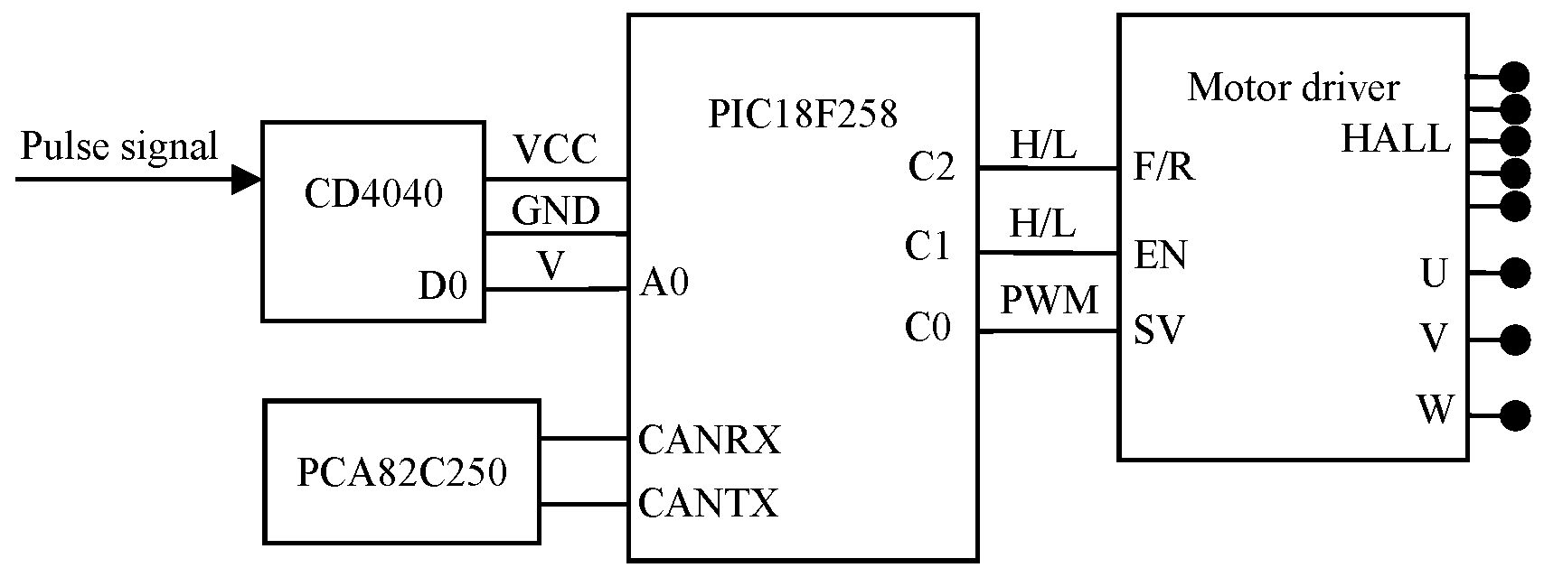
2.2.2. Control System

The control system of the garlic planter insertion mechanism primarily consists of the switch signal module, speed detection module, insertion drive module, pneumatic drive module, and remote control module. The overall structure is shown in Figure 4.
The overall architecture of the control system is designed with full consideration of module scalability and compatibility, while reserving ample space for future functional enhancements and system optimization to effectively accommodate the evolving requirements of agricultural production.
The proximity switch is utilized to detect the position of the sector-shaped rotating plate, while the hall sensor continuously monitors the machine’s travel speed. The controller receives remote control commands via a 2.4 G antenna from the remote control module. The brushless DC motor, connected to the front and rear transmission shafts via a chain, drives the insertion planting mechanism. The extension and retraction of the pneumatic cylinder [29,30] facilitate precise control of the crawler-type chassis steering, adjustment of garlic clove orientation, and operation of the insertion planting mechanism. The electronic control units (ECU) for the garlic planter’s engine start/stop, throttle, vehicle speed, steering, and operation must receive control commands from both the remote control and the navigation controller. The CAN-bus controller PCA82C250 was implemented as the physical interface to devices including the vehicle computer for information exchange, ensuring system transmission efficiency [31,32] and stability.

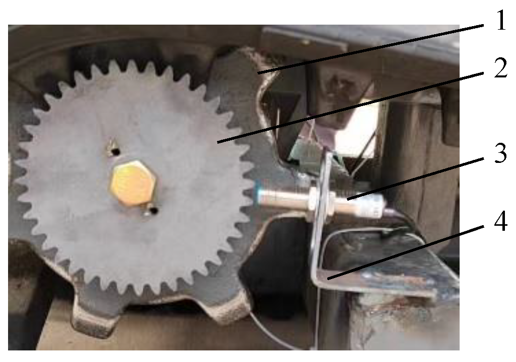
2.2.3. Speed Detection and Control

The machine is equipped with a speed detection device consisting of a hall sensor and gear, which enables real-time monitoring of the garlic planter’s speed, ensuring that the spacing between planting and sowing is consistent and uniform, as illustrated in Figure 5.
The sensor was installed near the drive wheel of the tracked chassis and aligned with the gears on the drive wheel. As the gear rotates, the hall sensor produces a pulse signal, where the number of pulses is directly proportional to the rotational speed. Consequently, the traveling speed of the planter can be determined based on this signal.
The selected hall sensor model is SC12-20K (Zhejiang Aotoro Electric Technology Co., Ltd., Yueqing, China), with an operating voltage of 5 V, NPN normally open type, and a response time of less than 60 ms. The hall sensor features high accuracy and reliability, a simple structure, and low cost, making it highly suitable for applications in agricultural machinery.
In this system, the speed controller receives the speed signal from the hall sensor, compares it with the pre-defined sowing speed, and outputs a control signal to the driver after performing PID calculations. This signal adjusts the motor speed, thereby controlling the insertion speed of the seeder. The speed controller consists of a single-chip microcomputer module and a plug-in driver.
The single-chip module, which is centered around the PIC18F258 microcontroller, integrates the CAN transceiver chip PCA82C250 and the pulse-counting chip CD4040, as depicted in Figure 6.

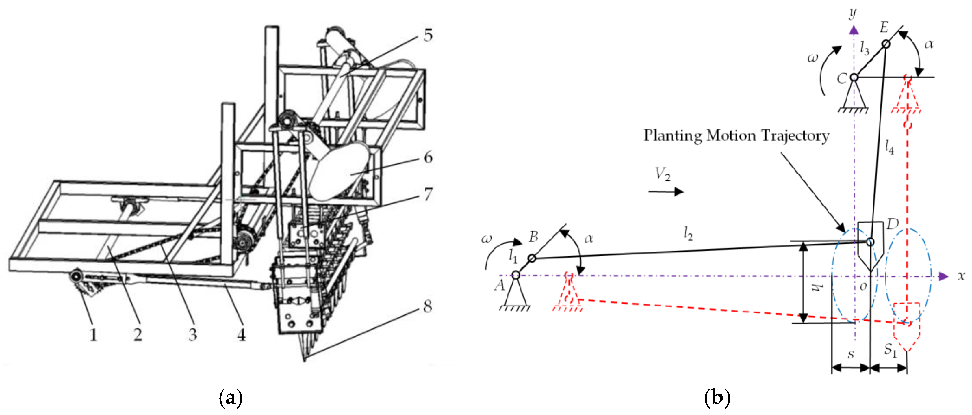
2.3. Design of the Insertion Planting Mechanism

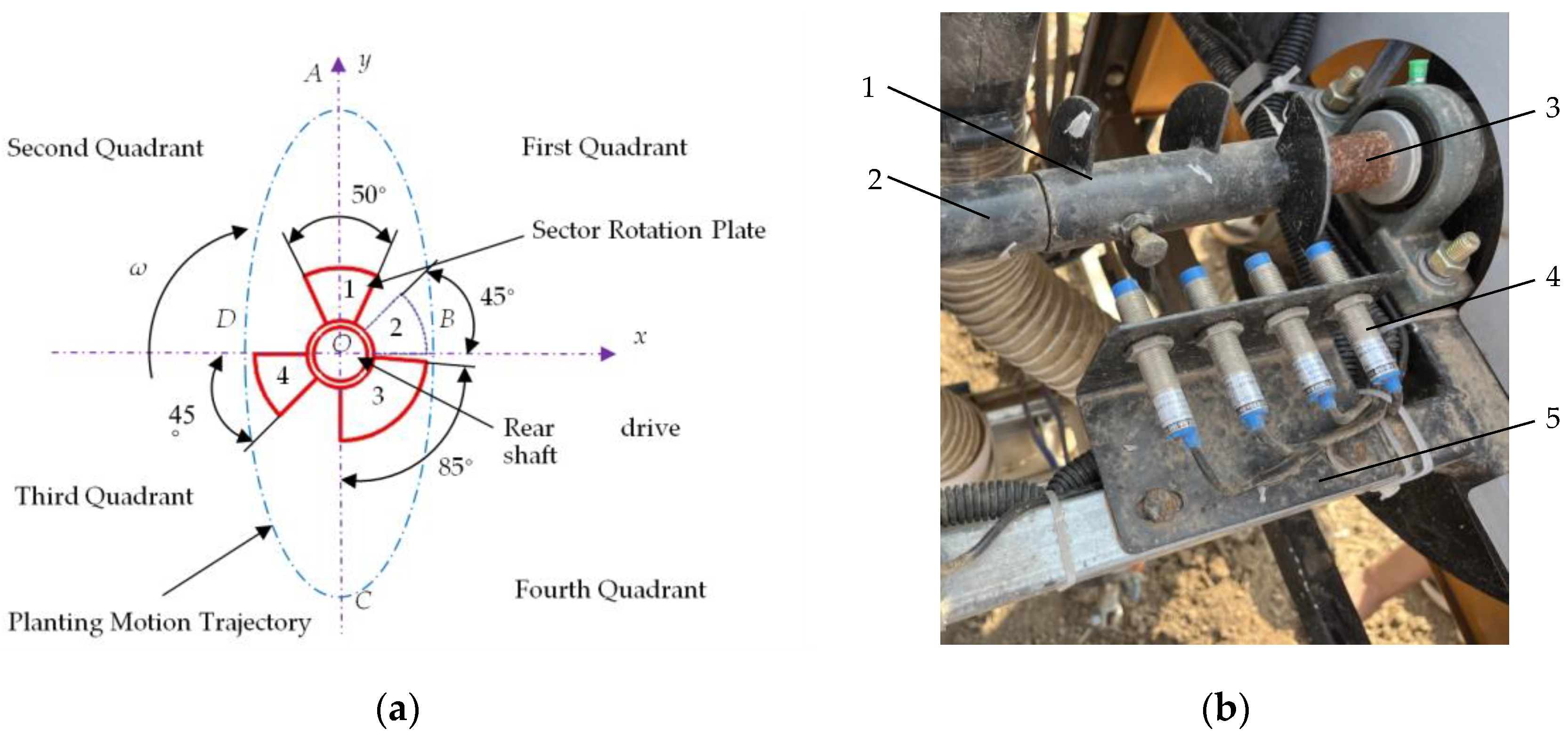
2.3.1. Kinematics Analysis of Insertion Mechanism

As depicted in Figure 7a, the designed insertion planting mechanism, which ensures the precise upright planting of oriented garlic cloves into the soil, comprises several key components: a driving sprocket, front transmission shaft, swing arm, rear transmission shaft, and duckbill planting insertor. Through the synchronized operation of two crank-rocker mechanisms, a reciprocating lifting system is formed that sequentially executes three distinct operational stages within a single motion cycle: receiving the garlic cloves upward, adjusting their orientation mid-cycle, and inserting them vertically into the soil.
As shown in Figure 7b, the displacements (s) and (h) of the implanting device in the x-axis and y-axis directions, respectively, can be calculated using Equations (1) and (2).
s = l 1 1 cos α + l 1 4 l 2 1 cos 2 α
h = l 3 1 + sin α + l 3 4 l 4 1 + cos 2 α
As depicted in Figure 8b, with rod l1 perpendicular to the x-axis serving as the initial position of motion (α = 0°), when the duckbill inserter reaches its highest point above the ground (α = 180°), the planted duckbill is inserted into the soil and rapidly opens, allowing the scale bud to fall into the seed hole. Simultaneously, as the duckbill opens, the soil flow immediately positions the scale bud. During this process, the duckbill inserter penetrates the soil, achieving a maximum stroke of smax = 2l1, after which the rotation continues. When the duckbill exits the soil, the surrounding soil covers the garlic seed, thereby completing the vertical planting operation. Additionally, when α equals 90° or 270°, the maximum height reached by the duckbill inserter is hmax = 2l3. To ensure an approximately elliptical motion trajectory for the duckbill feeder, the condition l3 > l1 must be satisfied, and the corresponding formula can be simplified as follows:
y 2 l 2 3 + x 2 l 2 1 = 1 , l 3 > l 1
Considering the operating speed, the motion equations are expressed as:
x = l 1 cos ω t + V 2 t y = l 3 sin ω t
V2 is the machine advancement speed, m/s; ω is the angular velocity of the driving swing arm (counterclockwise as positive), (°)/s; and t is the time, s.
The velocity ratio i, defined as the ratio of the horizontal velocity Vx to the vertical velocity Vy of the duckbill inserter during its motion, is closely associated with the shape of the cavitation movement trajectory. A higher value of i results in a smoother, longer, and narrower cavitation trajectory formed by the inserter.
i = V y V x
V x = ω l 1 sin ω t + l 1 2 l 2 sin 2 ω t
V y = ω l 3 sin ω t + l 3 2 l 4 sin 2 ω t
In the insertion mechanism, the relative motion between the moving parts will inevitably be affected by nonlinear friction, so in the actual operation process of the insertion mechanism, it is necessary to fully consider the influence of the nonlinear friction effect [33] on the motion of the mechanism.
Through discrete element simulation analysis, it is revealed that the influence of the insertion speed ratio on the upright degree is presented in Figure 8. It can be observed that within a reasonable range, the average insertion upright degree remains relatively high. However, values that are either too small or too large are not conducive to enhancing the insertion upright degree.
In loam soil, the seeding performance is optimal when the cloves are inserted into the planting mechanism. In clay soil, the consistency of seeding depth is acceptable owing to the high soil viscosity; however, in sandy soil, the consistency of seeding depth tends to be relatively poor. To enhance the vertical alignment of garlic insertion, it is advisable to loosen the soil prior to sowing or select a dry period for planting.
The speed ratio of the machine i is set to 2, with l3 measuring 100 mm and l1 measuring 50 mm. The depth of the subsequent duckbill insertion can be adjusted by modifying the length of l3.

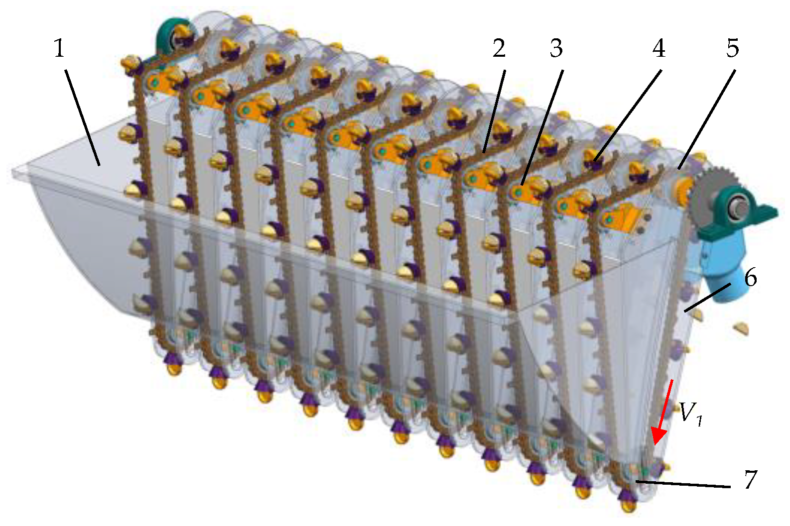
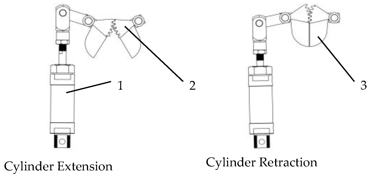
2.3.2. Design of the Single-Seed Extraction Mechanism

The chain-scoop seed extraction mechanism, renowned for its high single-seed extraction efficiency, has emerged as the predominant method for single-seed extraction both domestically and internationally [34]. The structural design of this single-seed extraction mechanism is illustrated in Figure 9.
In the seed selection process, a seed spoon is affixed to a conveying chain plate and moves diagonally upward from the bottom of the garlic seed box. As it passes over the seed-clearing sprocket, excess seeds are returned to the seed box, ensuring only one seed remains. The spoon then transitions to horizontal movement and, influenced by gravity, releases the single seed into the conveying tube as it passes the driving sprocket, thereby completing the precise single-seed selection process.
The conveying chain plate utilized is of the 08B type, featuring a single-sided single-hole flat design. To prevent multiple or missed sowings, the single-seed extraction mechanism must deliver one garlic clove into the conveying tube after each complete 360° rotation (one cycle) following the closure of the inoculation hopper. The movement speed of the spoon chain plate is dynamically adjusted in real-time according to the rotational speed of the planting mechanism, as detailed in Equations (8) and (9).
T = L 1 V 1 = P Z 0 V 1
i Z = Z 1 Z 0
T is the insertion cycle period, s; L1 is the seed scoop spacing, mm; V1 is the chain speed, m/s; P is the chain pitch, mm; iZ is the transmission ratio between the seed scoop sprocket and the institution mechanism; Z0 is the number of chain links between seed scoops; and Z1 is the number of teeth on the insertion drive sprocket.

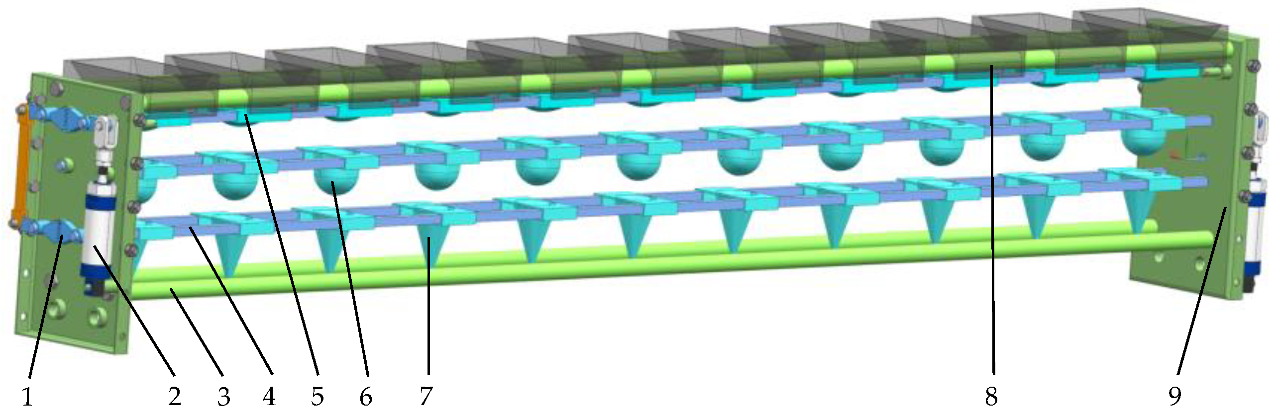
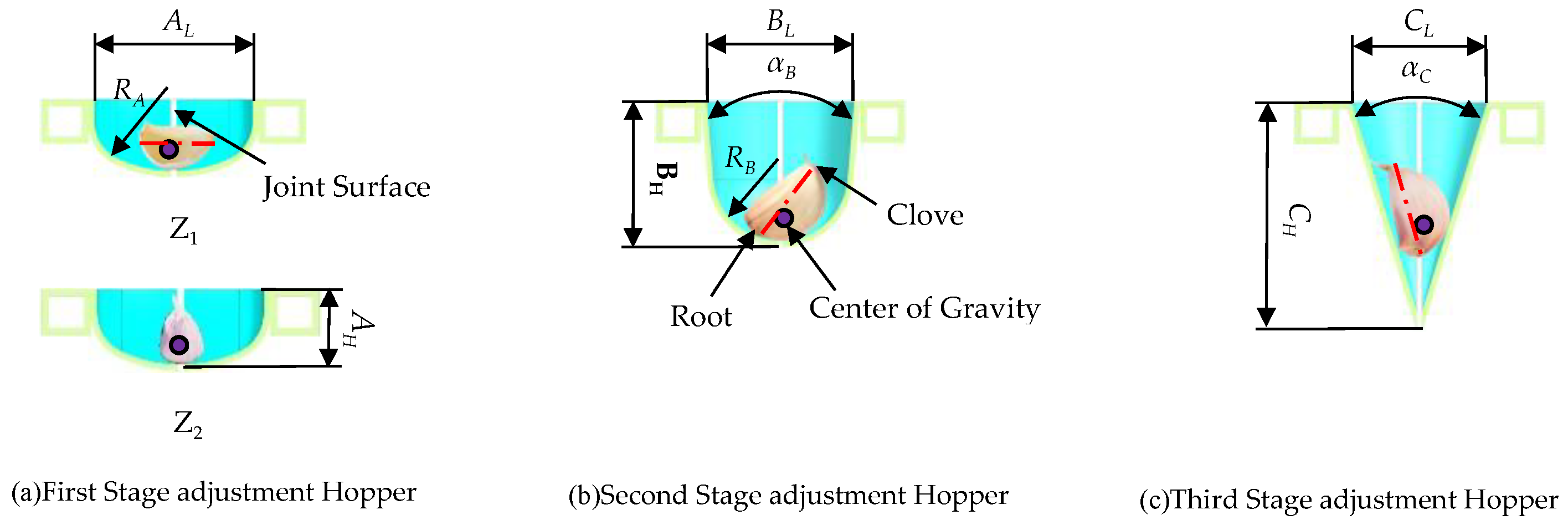
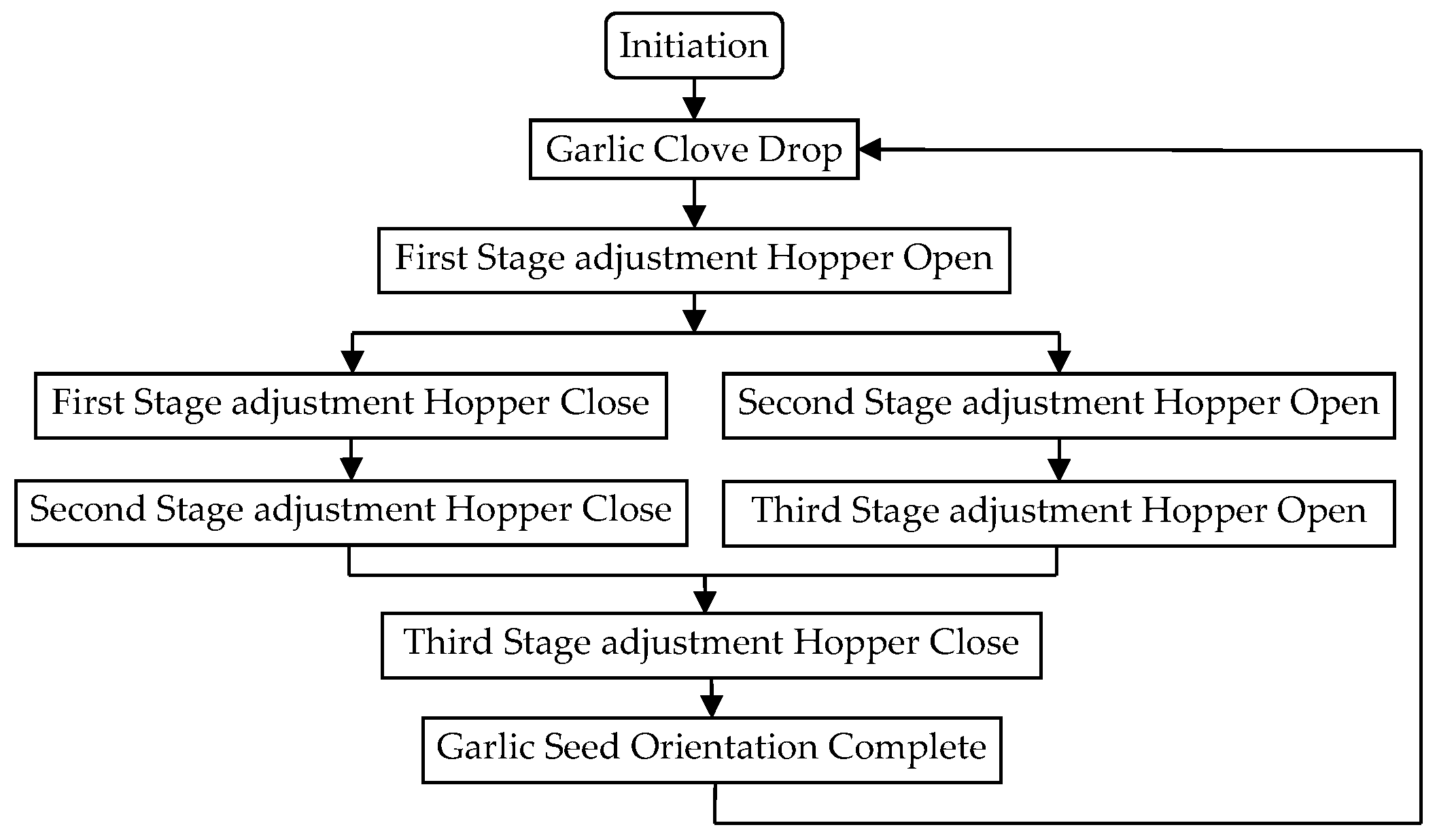
2.3.3. Design of the Adjustment Mechanism for Garlic Clove Direction

The core working component of the garlic planting insertion operation is the adjustment mechanism for garlic clove direction, as illustrated in Figure 10. The adjustment mechanism for garlic clove direction primarily consists of the three-stage adjustment hopper, square drive shaft, and transmission gear block.
The adjustment mechanism for orienting garlic cloves primarily leverages the distinctive morphological characteristics of garlic, such as the bow-shaped profile, the centroid proximity to the root end, and the elongated nature of the garlic cloves scales, in conjunction with the constraining effect of the hopper to achieve proper orientation, as illustrated in Figure 11.
Through the measurement of garlic clove dimensions, the average length was determined to be 31.6 mm, width 15.3 mm, thickness 18.8 mm, and the curvature at the back measured 15.8 mm (see Figure 11a). Under the influence of gravity, garlic cloves descend into the first directional hopper, colliding with the inner wall of the hopper. Therefore, the bottom is designed in a bowl shape to effectively accommodate the arc-shaped back of the garlic clove. The curvature radius of the hopper bottom is designed as RA of 40 mm, with a hopper opening diameter AL of 70 mm and a height AH of 25 mm. The spatial positioning of the garlic cloves can be categorized into two states: Z1, where the length direction of the garlic clove is perpendicular to the hopper joint surface, and Z2, where the length direction is parallel to the hopper joint surface. When the first stage adjustment hopper is opened, the garlic cloves fall. In state Z1, due to the longer side of the garlic sprout, the garlic clove will fall backward due to the blocking effect of the adjustment hopper on the sprout, while the shorter root side will detach from the hopper bottom first. In state Z2, as the center of gravity is closer to the garlic root, the support provided by the hopper at the widest point of the garlic clove will cause the root to detach from the hopper bottom first. In both states of Z1 and Z2, the garlic cloves enter the second-stage adjustment hopper with the sprout facing upward at the inclination angle.
As shown in Figure 11b, after the garlic cloves enter the second adjustment funnel, it is essential not only to restrict their horizontal positioning, but also to increase the inclination angle further. Compared to the first adjustment funnel, the design of the second adjustment funnel features a reduced outlet diameter, an increased height, and a smaller curvature radius at the bottom. Specifically, the parameters are defined as follows: the outlet diameter BL is 50 mm, height BH is 50 mm, and bottom curvature radius RB is 20 mm, with a cone angle αB of 20°.
As depicted in Figure 11c, the third adjustment funnel is designed to orient the garlic seeds in an upright status, necessitating a conical shape. Given that the garlic roots are narrow while the midsection is wider, and considering that the center of gravity is closer to the root, the garlic roots are secured in the apex of the cone, resulting in a status where the bottom-side (root) is down and pointy-tip (clove) is up. The designed conical funnel has an outlet diameter CL of 45 mm, a height CH of 80 mm, and a cone angle αC of 35°.

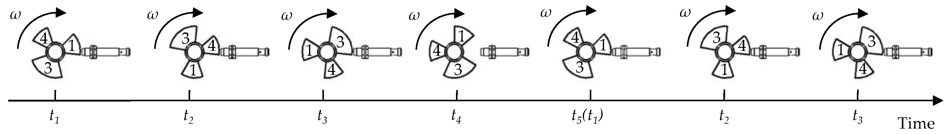
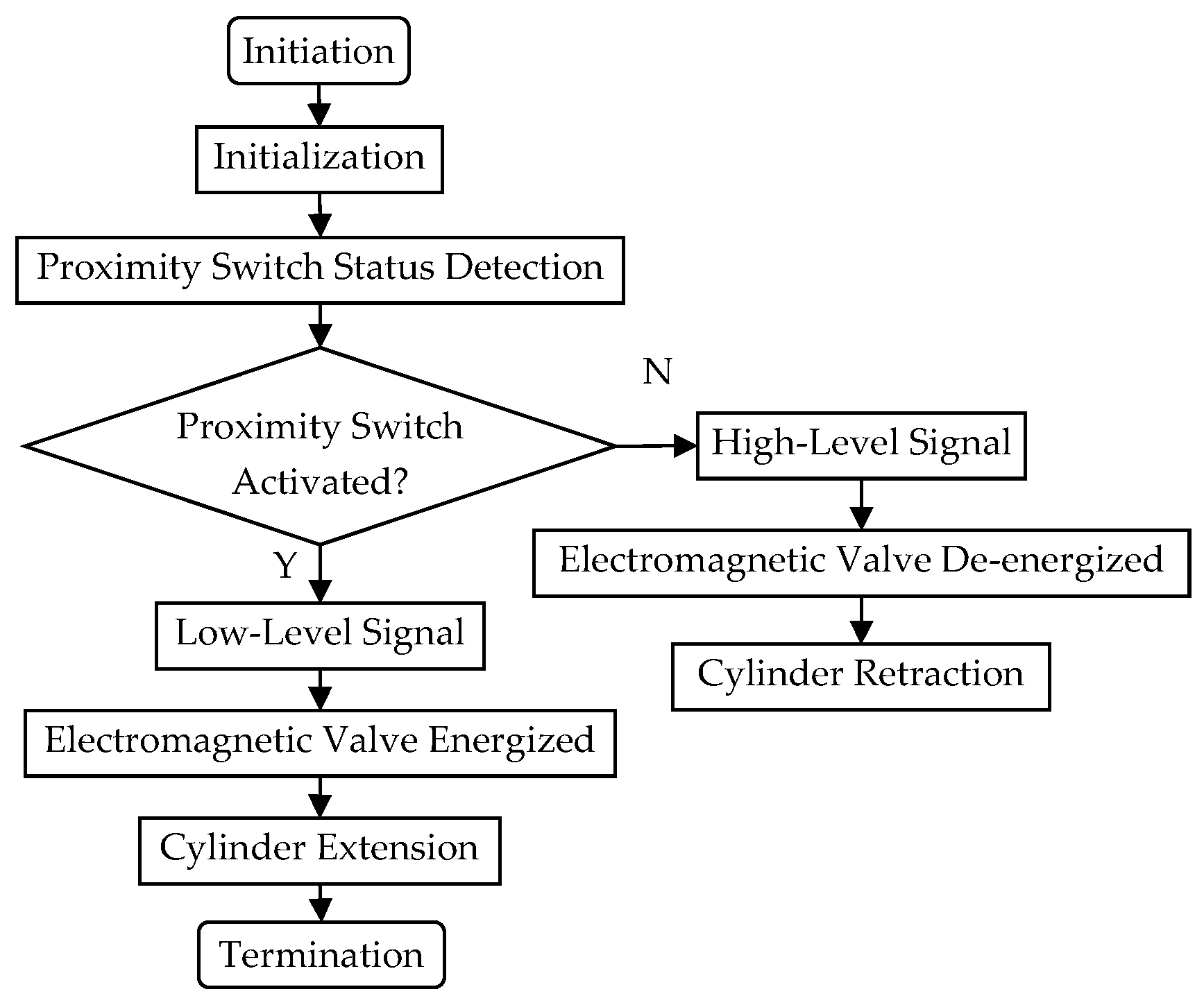
2.4. Timing Sequential Control Method

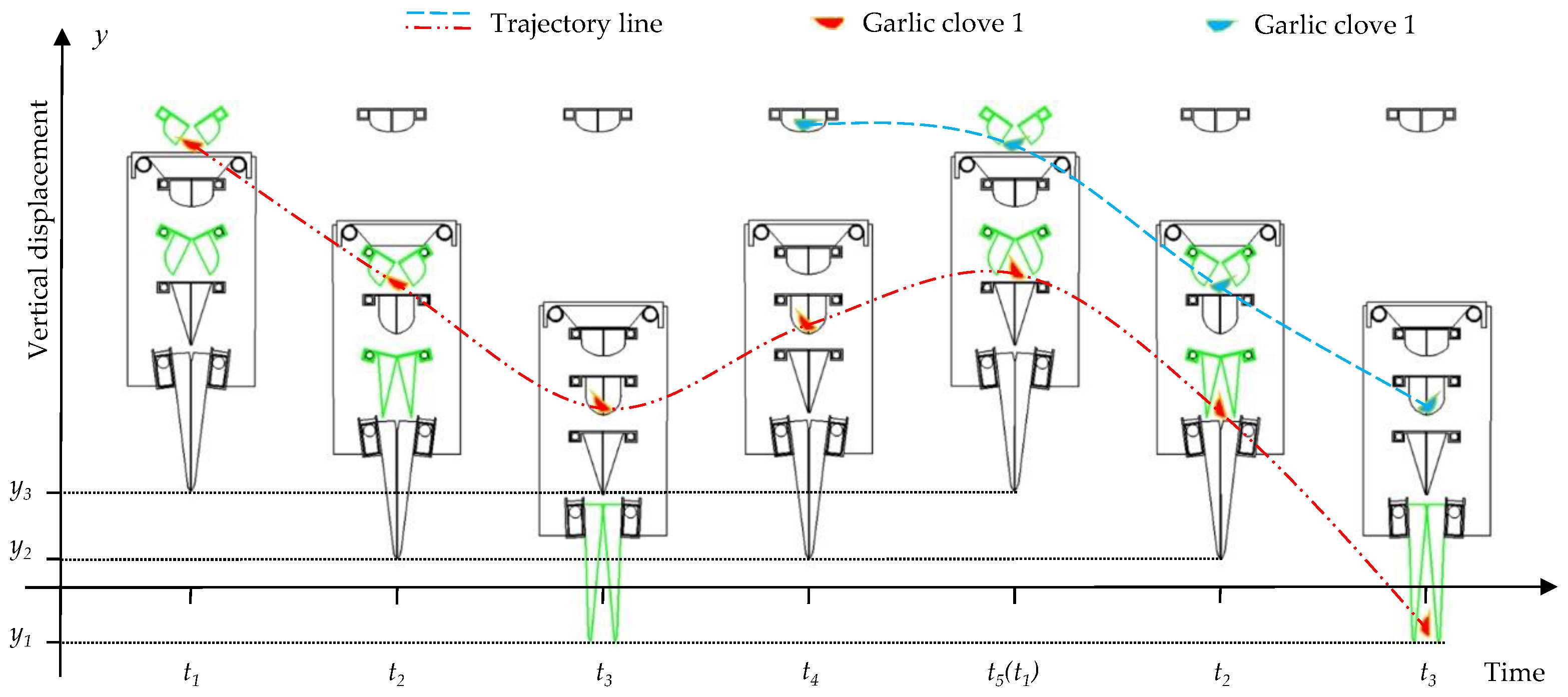
2.4.1. Time Sequence Control Method of Insertion of Planting Mechanism

Garlic insertion planting is a multi-step collaborative process. By meticulously scheduling the time sequence of these actions and ensuring their precise occurrence at the appropriate moments, the sowing process is maintained in an orderly manner. Based on the movement trajectory of the duck bill during a planting cycle, the seeding process has been categorized into three distinct states: seed-taking state, orientation state, and seeding state. The temporal intervals for each state within the planting cycle are illustrated in Figure 12.
When the duck’s beak is at position A, it transitions into the seed-acquisition state. At positions B and D, it transitions into the orientation state; at position C, it transitions into the sowing state. During seed acquisition, the frequency of seed-taking is ensured to align with the operational rhythm of the planting mechanism by adjusting the movement speed of the conveyor chain plate and the spacing of the seed scoop. The detailed working processes of the orientation and sowing states are illustrated in Figure 13, where the x-axis represents the time within an insertion rotation cycle, and the y-axis represents the vertical distance from the duck-splayed inserter to the soil surface.
At t1, the insertion mechanism is at the highest point from the ground (y3), at which time the inoculation hopper and the second-stage adjustment hopper open, and garlic seed 1 falls into the first-stage adjustment hopper. At t2, the insertion mechanism drops to (y2), and the first-stage and third-stage adjustment hopper open. The garlic seeds fall into the secondary adjustment hopper. At t3, the insertion mechanism is further lowered to the lowest point (y1) when the duckbill planting insertor is opened, but the garlic seed has not yet fallen into the duckbill planting insertor. Continue to t4, the planting mechanism leaves the soil and rises to the (y2) position, at which time the hopper at all levels does not open and close, and garlic seed 2 has been transferred to the inoculation hopper by the seed-taking mechanism. When it reaches t5, that is, when it returns to t1, an insertion cycle is completed, the insertion mechanism returns to the highest point (y3), the inoculation hopper and the second stage are opened, and garlic seed 1 enters the third-stage direction hopper. At the same time, garlic seed 2 falls into the first stage of the hopper. Then, for the t2 moment, the first stage of the hopper and the third stage of the hopper open. Garlic seed 1 is fed into the duckbill planting insertor and garlic seed 2 falls into the second stage of the adjustment hopper. Finally, at time t3, the duckbill inserter is inserted into the soil and turned on, and garlic seed 1 is planted upright in the soil, completing the planting of garlic seed 1. Continuing the movement will complete the planting of garlic seed 2, garlic seed 3, and more planting. The specific alignment work is shown in Figure 14.
Through this control mechanism, the insertion planting system completes one full rotation (360°) to accomplish the planting task for a single garlic clove. Each garlic clove undergoes 1.5 cycles within the planting mechanism, enabling the system to repeatedly perform the garlic planting operation through this cyclical motion.
In insertion planting operations, precise control is required for the timing of insertion and the opening of the duckbilled planter into the soil. Based on soil type and sowing depth requirements, the movement speed of the insertion planting mechanism and the structural parameters of the duckbill seeder are adjusted to ensure that the seeder penetrates the soil at the appropriate time and remains in the soil for a sufficient duration. This ensures that garlic cloves are accurately deposited into the soil, thereby completing the sowing operation effectively. Consequently, the design length of the duckbill inserter is set to 125 mm, with an actual soil penetration depth ranging from 0 to 90 mm, which satisfies the optimal garlic seeding depth range of 40 to 60 mm.
In the insertion planting control system, the adjustment hoppers and the duckbill planting insertor are controlled via a configuration of “proximity switch–electromagnetic valve–pneumatic cylinder”. As illustrated in Figure 15, the telescopic cylinders drive the rotation of the transmission gears. Each pair of gears is connected to two square shafts, with each adjustment hopper serially linked through these shafts. The duckbill planting insertor is mounted on the square tube, ensuring that the opening and closing actions of the adjustment hoppers at various levels can be synchronized.
During system testing, the interval between the fan rotor plate triggering the proximity switch and the hopper opening, as well as the fan rotor plate leaving the proximity switch and the hopper closing, is 0.4 to 0.6 s. When the system is activated or deactivated, the response time is 0.03 to 0.05 s, which has a negligible impact on system performance and can, therefore, be disregarded.

2.4.2. Design of the Time Sequence Signal

The elliptical motion trajectory of the planting mechanism can be mapped onto a Cartesian coordinate system in relation to the sector rotating plate, as illustrated in Figure 16a.
As shown in Figure 16a, when the insertion planting mechanism reaches the highest point (Point A), it is necessary to open the adjustment hopper to allow the garlic cloves to be dispensed into the adjustment device for garlic clove direction, followed by closing the hopper. The length of the inoculation hopper box is 80 mm. To prevent the phenomenon of clove leakage, a displacement margin of 20 mm to 25 mm is designed on each side of the zero point along the x-axis. Based on Equation (4), with a defined displacement margin of 22 mm, the corresponding angles are determined to be (65°, 115°). When the insertion planting mechanism moves to the lowest point (Point C), it is required that the duckbill planting insertor opens to plant the garlic cloves into the soil holes. The seeder must remain open until it has completely left the soil before closing. Considering that the planting depth for garlic seeds typically ranges from 40 mm to 60 mm, and taking into account potential obstacles on the soil surface such as uneven ground, fallen leaves, and weeds, it is designed that the duckbill planting insertor must lift at least 95 mm in the y-axis direction after opening at the lowest point (Point C) to ensure complete closure. According to Equation (2), the duckbill insertion planting mechanism must continue to rotate 85° (270°, 355°) from the lowest point for the duckbill planting insertor to close properly.
Points B and D will serve as reference points for controlling the opening and closing of the adjustment hopper, with a designed rotation angle of 45°. Consequently, the angles for the four sector-shaped rotating plates are determined to be 50°, 45°, 85°, and 45°, respectively. During one complete rotation of the insertion planting mechanism, it is sufficient for the first, third, and fourth sector rotation plate to send a signal to their corresponding proximity switches once each to achieve the sequential control of the inoculation hopper, adjustment hopper, and duckbill planting insertor.
The sector rotary plates are axially mounted on the rear drive shaft in the position and orientation depicted in Figure 16a. The corresponding proximity switches are installed on a bracket, with three proximity switches used to control the movement of the pneumatic cylinder of the insertion planting mechanism and one proximity switch ensuring that the insertion planting mechanism is positioned at its highest point from the ground when the operation is halted, as shown in Figure 13, at time t1. Therefore, two sector rotary plates need to be installed.
According to Figure 17, the sector rotary plates send signals to the corresponding proximity switches, corresponding one-to-one with the timing sequential insertion planting motion diagram depicted in Figure 13. The working time t for each rotary plate is defined as follows:
t = β 360 T
β is the angle of sector-shaped rotating plate (°).
The proximity switches used are of the model LJ12A3-4-Z/BY, NPN normally open type, operating at a voltage of 5 V, with an effective sensing distance of 10 mm.
When the sector rotation plate is near the proximity switch, it will trigger the proximity switch to work, output a low-level signal, and control the air switch to close meaning that the circuit of the pneumatic solenoid valve is open, the pneumatic solenoid valve changes the direction of the air pressure in the cylinder, and the cylinder is driven out. When the sector rotation plate leaves the proximity switch, the proximity switch stops working, outputs high-level signal, the air switch is disconnected, the pneumatic solenoid valve is powered off and then relies on the spring elasticity to restore the position and change the direction of the air pressure in the cylinder, and the cylinder retracts. The specific workflow is illustrated in Figure 18.
Summarizing the key parameters of the kinematic model and control system in a table would enhance readability, as shown in Table 2.

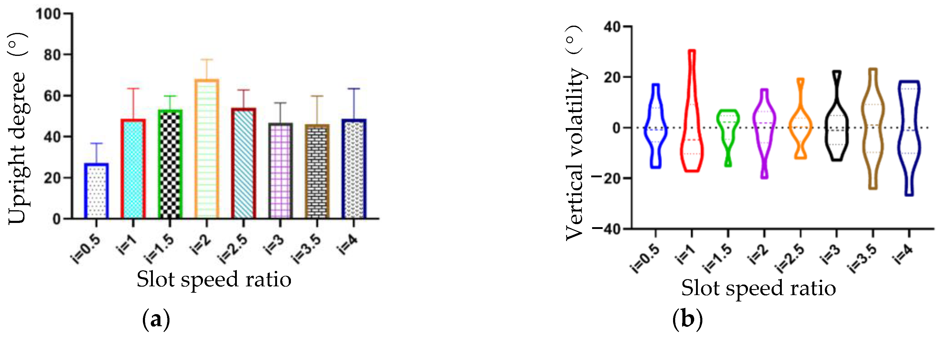
3. Results and Discussion

Field trials were conducted on 6 October 2024 at a garlic planting site in Jinan City, Shandong Province. As illustrated in Figure 19, the test area was partitioned into three plots, each featuring a field ridge distance of 3.9 m, a length of 150.0 m, and a ridge width of 0.6 m.
During the experiment, a handheld mobile point marker integrated with RTK-GNSS technology was utilized to accurately measure the coordinates of the two endpoints within the designated test area. The automatic navigation system subsequently generated an optimal operation path based on these coordinates, guiding the seeding machine along this predetermined route. The row spacing was set at 180 mm and the sowing spacing at 150 mm. The seeding machine operated at velocities of 0.10 m/s, 0.15 m/s, and 0.20 m/s in the first, second, and third plots, respectively, traversing back and forth within each plot. In the last line of the job, the speed is raised to 0.25 m/s to explore the sowing quality at a high speed, as shown in Figure 19a. Upon the completion of the operation, three rows from the central section of each plot were selected for evaluation. In each selected row, 100 consecutive garlic holes were measured to assess performance indicators including the row spacing accuracy, sowing spacing accuracy, single-seed rate, missing seeding rate, and upright rate, as shown in Figure 19b.
As shown in Figure 20, when the garlic seeder operates at speeds of 0.10 m/s, 0.15 m/s, and 0.20 m/s, the sowing spacing varies between 12.0 cm and 170 mm. After calculation, the average sowing spacing at these three speeds is 148 mm, 149 mm, and 151 mm, which closely matches the target value of 150 mm, with an error of less than 10 mm, far within the acceptable error range of ±30 mm. This fully demonstrates that the seeder has an excellent spacing control capability under different speed conditions, and can maintain high seeding accuracy and stability. Thanks to the precise single-seed and vertical seeding capabilities, accurate sowing spacing is of great significance for the growth of garlic, as it ensures that each plant receives sufficient space, light, and soil nutrients during its growth and development process. The plumpness of garlic cloves is enhanced, the occurrence of malformed garlic is reduced, and the market competitiveness of garlic is improved, which can substantially increase the economic benefits for farmers.
As shown in Table 3, when the garlic seeder operates at speeds of 0.10 m/s, 0.15 m/s, and 0.20 m/s, the maximum error values are 22 mm, 30 mm, and 27 mm, with root mean square (RMS) values of 5.7 mm, 5.2 mm, and 6.8 mm, and coefficients of variation of 0.038, 0.035, and 0.046, respectively. The increase in the coefficient of variation indicates that the increase in the operation speed reduces the consistency of the error in seeding spacing, and the stability of the operation performance is affected to some extent. The larger the RMS error, the larger the fluctuation range of the seeding spacing, and the larger the maximum seeding spacing deviation, thus reducing the reliability of the seeder. The stability of sowing spacing is crucial for ensuring the uniform growth of crops, as it can evenly distribute garlic plants in the field and help improve the overall yield and quality consistency. In addition, the single seed rate of the seeder exceeds 90%, the seedling leakage rate is less than 5%, and the upright rate is over 85%, all of which meet the requirements specified in the “General Technical Specifications for Garlic Seeders”.
It is evident that as the operational speed increases, the sowing spacing error, the missing sowing rate, and the upright rate all exhibit an upward trend. This trend is particularly pronounced at a speed of 0.25 m/s, where the decline in operational quality becomes apparent due to larger errors. This phenomenon can be attributed to the increased inertia of the transmission components during high-speed operation, which induces greater vibration during the processes of seed extraction and seeding, and the stability of the mechanism is then compromised, making it challenging to precisely control the sowing distance. The garlic seed delivery system may fail to transport the garlic seeds accurately and promptly to the designated sowing positions, thereby causing instances of missing sowing. The significant impact force experienced by the garlic seeds during orientation makes it difficult for them to maintain an upright position and embed properly into the soil.

4. Conclusions

In this study, we innovatively developed a design scheme of an insertion mechanism based on a double crank rocker mechanism, which cleverly combined the size of garlic cloves and agronomic requirements, used electronic control and pneumatic transmission technology, and adopted the timing control method to achieve an efficient and accurate automatic planting function. In the design, the proximity switch is used as a detection element to accurately monitor the rotation position and action time of the fan-shaped rotating plate to ensure that each component of the implant mechanism accurately performs the task in a predetermined time sequence. At the same time, the speed measuring device monitors the running speed in real time, and dynamically adjusts the insertion speed through the speed controller, so that the planting machine can adapt to different working environments and speed changes, ensuring the accuracy of the operation and the stability of the insertion process.
Traditional seeders are constrained by their single-function design, resulting in high seed-missing rates, garlic clove damage, inconsistent sowing depth and spacing, and an ultimately poor sowing quality. Due to their fixed operational modes, these seeders fail to address diverse agricultural requirements. This paper introduces a collaborative mechanism that achieves precise single-seed extraction and the controlled orientation of garlic cloves for upright planting, thereby significantly enhancing the sowing performance. Through an optimized structural design and precise timing control, consistent row spacing and sowing depth are ensured, leading to an improved sowing quality. By adjusting working components and operational parameters, the system demonstrates adaptability to various soil conditions and garlic varieties. With advanced electrical control systems and navigation support, the proposed mechanism not only boosts the planting efficiency, but also minimizes manual intervention, ultimately maximizing economic benefits. The mechanism still exhibits certain limitations. Garlic cloves need to be screened to ensure proper orientation and successful planting. The duckbill planting insertor is in prolonged contact with different types of soil and the opening and closing components are prone to wear, compromise both accuracy and longevity. By encountering high winds or complex terrains, vibrations may lead to deviations in sensor data. To address these issues, high-hardness and wear-resistant materials must be used to make duckbill planting insertors; multi-sensor fusion technology can be employed to enhance adaptability and data precision. For garlic varieties characterized by irregular shapes and significant size variations, the seed-taking and orientation mechanism can be optimized by incorporating adjustable components, thereby ensuring compatibility with diverse varieties.
In order to further improve the performance of seeders under high-speed operation, future research should focus on optimizing the dynamic design of seed picking and sowing mechanisms to enhance their response accuracy and stability under high-speed conditions. Future studies also will further explore how to deeply integrate the institution with smart agriculture technology [35], such as introducing machine learning algorithms, so that the planter can automatically adjust the planting parameters according to soil conditions, climate data, etc., to achieve more intelligent and accurate planting operations. At the same time, we can study how to expand the institution to the cultivation of other crops, promote the comprehensive upgrading of agricultural planting technology, and provide more diversified and efficient solutions for agricultural production.

Author Contributions

X.Y., J.D. and L.Y. conceived and designed the experiments; G.C., Y.Y. and J.C. performed the experiments; X.Y. and G.C. analyzed the data; G.C. wrote the draft manuscript; X.Y. and J.D. revised the manuscript. All authors have read and agreed to the published version of the manuscript.

Funding

This work was supported by the Key R&D Program of Shandong Province, China (2022SFGC0201), the National Key Research and Development Program, the National Natural Science Foundation of China (32171910), and the National Key Research and Development Program (2021YFD2000502).

Institutional Review Board Statement

Not applicable.

Data Availability Statement

The data presented in this study are available on demand from the first author at chenguilin52521@163.com.

Conflicts of Interest

Author Jun Chong was employed by the company Ji’nan Huaqing Agricultural Machinery Technology Co., Ltd. The remaining authors declare that the research was conducted in the absence of any commercial or financial relationships that could be construed as a potential conflict of interest.

References

  1. Furdak, P.; Pieńkowska, N.; Bartosz, G.; Sadowska-Bartosz, I. Extracts of Common Vegetables Inhibit the Growth of Ovary Cancer Cells. Foods 2022, 11, 2518. [Google Scholar] [CrossRef]
  2. Thomas, A.; Boobyer, C.; Borgonha, Z.; van den Heuvel, E.; Appleton, K.M. Adding Flavours: Use of and Attitudes towards Sauces and Seasonings in a Sample of Community-Dwelling UK Older Adults. Foods 2021, 10, 2828. [Google Scholar] [CrossRef] [PubMed]
  3. Yang, X. Industrial status and development countermeasures of garlic industry in China. Chin. Fruit Veg. 2020, 40, 57–59. [Google Scholar]
  4. Li, C.; Feng, R.; Xu, H.; Sun, Q.; Song, J.; Jin, C. Research status and prospect of garlic seed classifier. J. Chin. Agric. Mech. 2021, 42, 91–96. [Google Scholar]
  5. Jin, C.Q.; Yuan, W.S.; Wu, C.Y.; Zhang, M. Experimental study on effects of the clove direction on garlic growth. Trans. Chin. Soc. Agric. Eng. 2008, 24, 155–158. [Google Scholar]
  6. Liu, J.; Qin, Y.; Wang, L.X.; Liu, Z.L.; Zhou, L.J.; Zhang, Y.F.; Liu, S.Q. Effects of different varieties and different planting patterns on the growth and quality and yield of aquicultural garlic seedlings. Acta Hortic. Sin. 2018, 45, 959–966. [Google Scholar]
  7. Geng, A.; Li, X.; Hou, J.; Zhang, Z.; Zhang, J.; Chong, J. Design and Test of Automatic Directional Garlic Planter. Trans. Chin. Soc. Agric. Eng. 2018, 34, 17–25. [Google Scholar]
  8. Han, Q.; Wang, X.; Hao, J.; Xie, L.; Yv, J. Design and Research of Inserting Hole Type Automatic Directional Garlic Planter. Agric. Mech. Res. 2016, 38, 172–175. [Google Scholar]
  9. Li, Y.; Niu, C.; Jia, S. Analysis of the Current Research Situation on Mechanized Garlic Seeding. Xinjiang Agric. Mech. 2021, 2, 29–33. [Google Scholar]
  10. Li, T.; Huang, S.; Niu, Z. Optimization and experiment of planting perpendicularity of planetary wheel garlic planter. Trans. Chin. Soc. Agric. Eng. (Trans. CSAE) 2020, 36, 37–45. [Google Scholar]
  11. Kim, L.H. Garlic Planter. KR20160007470A, 20 January 2016. [Google Scholar]
  12. Choi, D.-K.; Park, W.-K.; Kang, T.-G.; Park, S.-H.; Kim, H.-J.; Kwak, T.-Y.; Kim, Y.-K. Garlic Upright-Positioning and Planting Device. US2003084830A1, 8 May 2003. [Google Scholar]
  13. Kyoon, E.Y. Upright Arrangement Planter Device of Garlic Seed. KR20190126973A, 13 November 2019. [Google Scholar]
  14. Xie, D.; Zhang, C.; Wu, X. Design and Test of Garlic Seed Placer with Seed Disturbing Tooth Assisted Air Suction. Trans. Chin. Soc. Agric. Mach. 2022, 53, 47–57. [Google Scholar]
  15. Li, T.; Zhang, H.; Han, X.; Li, Y.; Hou, J.; Shi, G. Design and experiment of missing seed detection and the reseeding device for spoon chain garlic seeders. Trans. Chin. Soc. Agric. Eng. (Trans. CSAE) 2022, 38, 24–32. [Google Scholar]
  16. Li, Y.H.; Zhang, Z.L.; Li, T.H.; Hou, J.L. Design and experiment of wheel-spoon type garlic precision seed-picking device. Trans. Chin. Soc. Agric. Mach. 2020, 51, 61–68. [Google Scholar]
  17. Geng, A.J.; Li, X.Y.; Hou, J.J.; Zhang, J.; Zhang, Z.L.; Chong, J. Design and experiment of automatic garlic seed directing device. Int. J. Agric. Biol. Eng. 2020, 13, 85–93. [Google Scholar] [CrossRef]
  18. Hou, J.L.; Tian, L.; Li, T.H.; Niu, Z.R.; Li, Y.H. Design and experiment of test bench for garlic bulbil adjustment and seeding based on bilateral image identification. Trans. Chin. Soc. Agric. Eng. Trans. CSAE 2020, 36, 50–58. [Google Scholar]
  19. Cseresnyés, I.; Szitár, K.; Rajkai, K.; Füzy, A.; Mikó, P.; Kovács, R.; Takács, T. Application of electrical capacitance method for prediction of plant root mass and activity in field-grown crops. Front. Plant Sci. 2018, 9, 93. [Google Scholar] [CrossRef] [PubMed]
  20. Mohapatra, A.; Shanmugasundaram, S.; Malmathanraj, R. Grading of ripening stages of red banana using dielectric properties changes and image processing approach. Comput. Electron. Agric. 2017, 143, 100–110. [Google Scholar] [CrossRef]
  21. Akbari, A.; Kouravand, S. Developing a temperature measuring system model for agriculture dryer with consideration of fringing field effect in mathematical modeling. Comput. Electron. Agric. 2018, 146, 59–65. [Google Scholar] [CrossRef]
  22. Zhu, Z.; Cao, X.; Zhang, R. Optimal design of garlic clove’s orientation adjustment system based on parallel robot. J. Intell. Agric. Mech. 2023, 4, 20–25. [Google Scholar]
  23. Wang, X.; Cui, R.; Xu, W.; Jian, S.; Ma, J. A Garlic Seed Bud Direction Adjusting Device for Garlic Seeder. Chinese Invention Patent No. CN201420650675.6, 11 March 2015. [Google Scholar]
  24. Liu, J.; Geng, A.; Li, X.; Hou, J.; Han, X. Research status of garlic planting machine single seed-filling and resow. Agric. Mech. Res. 2019, 41, 262–268. [Google Scholar]
  25. Wei, H.; Wang, X.; Chen, J. Discussion on the present situation and development of mechanized garlic production in China. J. Chin. Agric. Mech. 2022, 43, 175–182. [Google Scholar]
  26. Li, X.; Geng, A.; Hou, J.; Zhang, M.; Zhang, J.; Li, W. Research status and prospect of garlic planter. Farm Mac. 2017, 2, 105–107. [Google Scholar]
  27. Li, Y.; Chen, J.; Liang, Z.; Ma, X.; Jiang, X. Design and Experiment of Differential Steering Mechanism for Track Combine Harvester. Trans. Chin. Soc. Agric. Mach. 2016, 47, 127–134. [Google Scholar]
  28. Pan, G.; Yang, F.; Sun, J.; Liu, Z. Analysis and Test of Obstacle Negotiation Performance of Small Hillside Crawler Tractor during Climbing Process. Trans. Chin. Soc. Agric. Mach. 2020, 51, 374–383. [Google Scholar]
  29. Shi, S.; Zhang, D.; Yang, L.; Cui, T.; Li, K.; Yin, X. Simulation and verification of the filling performance of the pneumatic combined hole-type seed metering device based on EDEM software. Trans. Chin. Soc. Agric. Eng. 2015, 31, 62–69. [Google Scholar]
  30. Furuhata, M.; Chosa, T.; Shioya, Y.; Tsukamoto, T.; Seki, M.; Hosokawa, H. Developing Direct Seeding Cultivation Using an Air-Assisted Strip Seeder. Jpn. Agric. Res. Q. 2015, 49, 227–233. [Google Scholar] [CrossRef]
  31. Ling, L.; Xiao, Y.; Huang, X.; Wu, G.; Li, L.; Yan, B.; Geng, D. Design and Testing of Electric Drive System for Maize Precision Seeder. Agriculture 2024, 14, 1778. [Google Scholar] [CrossRef]
  32. Miao, W.; Zhou, Z.; Xuan, J.; Cheng, D.; Cao, N. Design and simulation of ball balancing robot controller based on fuzzy PID. Transducer Microsyst. Technol. 2021, 40, 66–70. [Google Scholar]
  33. Fotuhi, M.J.; Ben Hazem, Z.; Bingül, Z. Modelling and Torque Control of an Non—Linear Friction Inverted Pendulum driven with a Rotary Series Elastic Actuator. In Proceedings of the 2019 3rd International Symposium on Multidisciplinary Studies and Innovative Technologies (ISMSIT), Ankara, Turkey, 11–13 October 2019; pp. 1–6. [Google Scholar]
  34. Lai, Q.; Jia, G.; Su, W. Design and Test of Chain-spoon Type Precision Seed-metering Device for Ginseng Based on DEM-MBD Coupling. Trans. Chin. Soc. Agric. Mach. 2022, 53, 91–104. [Google Scholar]
  35. Li, M.; Wu, F.; Wang, F.; Zou, T.; Li, M.; Xiao, X. CNN-MLP-Based Configurable Robotic Arm for Smart Agriculture. Agriculture 2024, 14, 1624. [Google Scholar] [CrossRef]
Figure 1. Cultivation mode of the garlic.
Agriculture 15 00849 g001
Figure 2. Dimensions of the garlic clove appearance. AS is the length of the garlic seed; BS is the thickness of the garlic seed; CS is the width of the garlic seed; DS is the sprout tip length of the garlic seed.
Agriculture 15 00849 g002
Figure 3. The crawler-type garlic seeder platform. 1. DC motor. 2. Air pump. 3. Single-seed extraction mechanism. 4. Proximity switch device. 5. Adjustment mechanism for garlic clove direction. 6. Duckbill planting insertor. 7. Crawler-type chassis. 8. Speed measuring device.
Agriculture 15 00849 g003
Figure 4. Diagram of the control system of the garlic planter.
Agriculture 15 00849 g004
Figure 5. Speed measurement device. 1. Track chassis drive wheel. 2. Gear disc. 3. Hall sensor. 4. L-type bracket.
Agriculture 15 00849 g005
Figure 6. Diagram of the speed controller.
Agriculture 15 00849 g006
Figure 7. The insertion planting mechanism and insertion motion model diagram. (a) The insertion planting mechanism. 1. Driving sprocket. 2. Front transmission shaft. 3. Drive chain. 4. Transverse swing arm. 5. Rear transmission shaft. 6. Balance hammer. 7. Lifting swing arm. 8. Duckbill planting insertor. (b) Insertion motion model diagram. Duckbill planting insertor l1 is the length of the active swing arm AB; l2 is the length of the driven connecting rod BD; l3 is the length of the active swing arm CF; l4 is the length of the driven connecting rod ED; α is the rotational angle of the active swing arm; and S1 denotes the displacement of the duckbill inserter when the angle α is rotated to 0°.
Agriculture 15 00849 g007
Figure 8. Effect of insertion speed ratio on upright degree; (a) upright degree; (b) vertical volatility.
Agriculture 15 00849 g008
Figure 9. Schematic diagram of single-seed extraction device structure. 1. Garlic seed box. 2. Conveying chain plate. 3. Seed-clearing sprocket. 4. Seed extraction spoon. 5. Drive sprocket. 6. Conveying tube. 7. Tensioning sprocket.
Agriculture 15 00849 g009
Figure 10. Schematic diagram of adjustment mechanism for garlic clove direction. 1. Transmission gear block. 2. Pneumatic Cylinder. 3. Support shaft. 4. Square drive shaft. 5. First-stage adjustment hopper. 6. Second-stage adjustment hopper. 7. Third-stage adjustment hopper. 8. Inoculation square-shaped box. 9. Mounting plate.
Agriculture 15 00849 g010
Figure 11. Orientation method of the garlic seed.
Agriculture 15 00849 g011
Figure 12. Time sequential working time area cycle division diagram.
Agriculture 15 00849 g012
Figure 13. Timing sequential insertion planting motion diagram.
Agriculture 15 00849 g013
Figure 14. Garlic seeds’ automatic alignment work flow chart.
Agriculture 15 00849 g014
Figure 15. Orientation method of the garlic seed. 1. Pneumatic cylinder. 2. Transmission gear block. 3. Adjustment hopper.
Agriculture 15 00849 g015
Figure 16. The relationship diagram between the planting motion trajectory and the sector rotation plate. (a) Cartesian coordinate system diagram. (b) Proximity switch device. 1. Rotating sleeve. 2. Rear drive shaft. 3. Sector rotation plate. 4. Proximity switch. 5. Support bracket.
Agriculture 15 00849 g016
Figure 17. Signal timing diagram of proximity switch activation.
Agriculture 15 00849 g017
Figure 18. Workflow diagram for proximity switch control.
Agriculture 15 00849 g018
Figure 19. Field experiment. (a) Experimental conditions. (b) Sowing spacing measurement. The red numbers in Figure 19a indicate the three plots in the experimental area.
Agriculture 15 00849 g019
Figure 20. Variation of the seed sowing spacing. (a) v = 0.1 m/s. (b) v = 0.15 m/s. (c) v = 0.2 m/s.
Agriculture 15 00849 g020
Table 1. The primary technical parameters of the garlic seeder.
Project TitleUnitProject Parameters
Machine dimensions
(length × width × height)
m2.4 × 1.9 × 1.4
PowerkW8
Operating Speedm·s−18–12
Sowing efficiencym2·h−1500–600
RowsRow11
Row spacingmm90–500 (Adjustable)
Sowing spacingmm60–200 (Adjustable)
Sowing depthmm30–60 (Adjustable)
Table 2. The key parameters of kinematic model and control system.
Parameter NameParameter MeaningValue
l1Length of active swing arm AB50–100 mm (Adjustable)
l3Length of active swing arm CE100 mm
αThe rotation angle of the active swing arm0–360°
hmaxThe maximum height of the implanted device in the Y-axis direction2l3
smaxThe maximum displacement of the implant in the X-axis direction2l1
V2Planter advance speed0–0.2 m/s (Adjustable)
βThe angle of the fan rotation plate50°, 45°, 85°
TInsertion cycleAccording to the operation speed and planting spacing
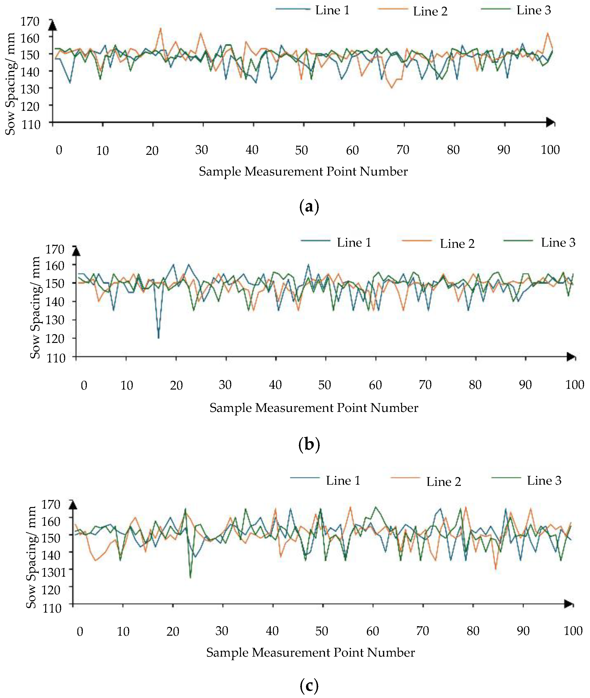
Table 3. Comparison of experimental results.
Operating Speed/m·s−1Sowing Spacing Deviation ErrorMissing Seeding Rate/%Upright Rate/%Single-Seed Rate/%
Maximum
/mm
Average
/mm
RMS
/mm
Coefficient of Variation
0.10223.85.70.0382.387.391.7
0.15303.45.20.0352.786.390.7
0.20274.96.80.0463.385.390.3
0.25384.310.20.0585.372.386.4
Disclaimer/Publisher’s Note: The statements, opinions and data contained in all publications are solely those of the individual author(s) and contributor(s) and not of MDPI and/or the editor(s). MDPI and/or the editor(s) disclaim responsibility for any injury to people or property resulting from any ideas, methods, instructions or products referred to in the content.

