Article

Design and Experimental Study of a Dual-Side-Disturbance-Facilitated Air-Suction Precision Seed Metering Device for Corn

1
School of Mechanical and Automotive Engineering, Qingdao University of Technology, Qingdao 266520, China
2
State Key Laboratory of Mechanical Transmission, Chongqing University, Chongqing 400044, China
*
Author to whom correspondence should be addressed.
Agriculture 2025, 15(7), 763; https://doi.org/10.3390/agriculture15070763
Submission received: 7 February 2025 / Revised: 10 March 2025 / Accepted: 26 March 2025 / Published: 2 April 2025
(This article belongs to the Section Agricultural Technology)

Abstract

:
To address the issue of a poor seed-filling performance and seeding quality in air-suction corn seed metering devices during high-speed operation, an energy-efficient precision corn seeder with dual-side-disturbance-facilitated guiding slots is designed. The dual-side-disturbance-promoting method effectively increases the seed agitation, directing the corn seeds toward the suction holes and improving the seed-filling quality. The theoretical design of the dual-side guiding slot angles results in an upper-side guiding slot angle range of 29° to 19° and a lower-side guiding slot angle range of 72° to 90°. Bench tests are conducted to further optimize the parameter range, with the negative suction chamber pressure, upper-side guiding slot angle, and lower-side guiding slot angle as the experimental factors and the seedling qualification rate, missed sowing rate, and double-sowing rate as the evaluation indicators. An orthogonal experiment is carried out to analyze the interaction effects of factors on the evaluation indicators, followed by parameter optimization and verification tests. When the negative suction chamber pressure is 3.7 kPa, the upper-side guiding slot angle is 26.9°, and the lower-side guiding slot angle is 72.9°, the verification test results show a qualification index of 97.7%, a missed sowing index of 1.3%, and a row-spacing variation coefficient of 1%. The operational speed adaptability test results show that when the working speed is ≤14 km/h, the seed metering device achieves a qualification index above 97.1%, a missed sowing index below 1.5%, and a double sowing index below 1.4%, indicating good adaptability to working speeds. The comparison test results show that when the operating speed is between 8 and 12 km/h, the air-suction seed metering device with dual-side-disturbance-facilitated guiding slots achieves a 2.1% increase in the qualification index, significantly improving seeding quality. The energy consumption comparison test results indicate that under the same operational speed and approximately equal seeding quality, the air-suction seed metering device with dual-side guiding slots and dual-side-disturbance-facilitated air suction requires a reduction in negative pressure of more than 0.7 kPa, resulting in lower energy consumption.

1. Introduction

Sowing is a critical step in corn production, and improving the sowing quality is the most direct and effective technical measure to increase the yield per unit area [1,2,3,4]. The seed metering device is the core component of corn seeding machinery, and its operational performance directly affects the sowing quality [5,6,7,8]. Pneumatic seeders are widely used due to their strong adaptability to corn seeds, low seed damage, and good seeding accuracy at high operating speeds [9,10]. However, the method of increasing the negative suction chamber pressure to improve the seed-filling quality during high-speed operation leads to significant energy consumption, which is unfavorable for energy conservation and emission reduction [11,12]. To reduce energy consumption while ensuring the high-speed performance of air-suction seed metering devices, both domestic and international researchers have conducted extensive studies [13,14,15,16,17,18]. Li Ding et al. [19] found that the poor design of the seed disc and vacuum chamber led to an unsatisfactory seeding performance in high-speed operations for air-suction precision corn seeders. To address this, they designed an air-suction corn seed metering device with auxiliary guidance to achieve high-speed, precise seeding. They proposed an auxiliary guidance seeding theory and developed a seed disc structure with apertures to optimize the seeding quality. Yecheng Wang et al. [20] explored a controllable friction-type vertical disc precision seed metering device to enhance the seed charging force, thereby improving the maximum operating speed of existing mechanical seeders and achieving high-speed seeding. Bereket, B.Z. et al. [21] studied the impact of different structural parameters required for various operations on the seed metering device’s single-seed precision planting performance and analyzed how different seeding modules affect the uniformity of the seed-sowing performance. Pareek, C.M. et al. [22] set out to improve the seed-filling performance indicators, and they found that the tilt angle exhibited a nonlinear relationship. An artificial neural network with sufficient complexity can capture these relationships. The integrated ANN-PSO method is used to optimize the seed-filling performance of the inclined-plate seeding device. Wang Dong Wei et al. [23] designed a seed disc with a combined seed-suction aperture structure to address issues like double seeding and missed seeding in air-suction seeders during peanut-planting operations. This design incorporates seed disturbance, seed propulsion, and auxiliary seeding functions to ensure a good seeding performance at high speeds. Ding Li et al. [24] designed a seeding area that uses aperture protrusions to disturb seed populations and support the seeds, improving the seeding quality in air-suction precision corn seeders at higher working speeds. They also addressed the problems of severe missed seeding and high wind pressure demand. Davut Karayel et al. [25] used artificial neural networks to estimate the optimal vacuum pressure for air-suction seeders, which is a critical factor influencing the seeding quality and final seedling emergence rate.
To address the excessive energy consumption when increasing the negative suction chamber pressure in air-suction seed metering devices for high-speed operations, this paper proposes a dual-side-disturbance-facilitated air-suction precision seed metering device. By using dual-side disturbance to guide the seeds toward the suction holes, the design improves the seeding quality without increasing energy consumption, ensuring the seeding performance of the device. Traditional pneumatic seeders experience a decrease in seed-filling quality due to seed crowding at high operating speeds. The dual-side-disturbance-facilitated air-suction seed metering device designed in this study can effectively improve the seed flow and increase the seed-filling quality during high-speed operation by using guiding slots to induce disturbances.

2. The Overall Structure and Working Principle of the Dual-Side Disturbance-Facilitated Air-Suction Precision Seed Metering Device

2.1. Overall Structure of the Dual-Side-Disturbance-Facilitated Air-Suction Precision Seed Metering Device

As shown in Figure 1, this seed planter mainly consists of a seed disc, rear housing, seed cleaning frame, seed cleaning wheel, seed disc fixing component, seed disc end cap, drive shaft, air channel, and seed discharge outlet. The motor drives the seed disc through the drive shaft and the seed disc fixing component. The seed planter adopts a dual-side guided disturbance seed-filling method, with flow guide grooves set along the circumference of the seed disc to direct seeds into the suction hole’s effective range. Additionally, a guide groove is set on the inner side of the suction hole to guide the seeds for filling from both sides. The seed-cleaning device uses a multi-position seed-cleaning wheel mechanism, and the seed-dropping method employs an air-blocking seed-dropping approach, ensuring that the airflow is blocked before directly releasing to atmospheric pressure, preventing seeds from being affected by negative-pressure airflow.

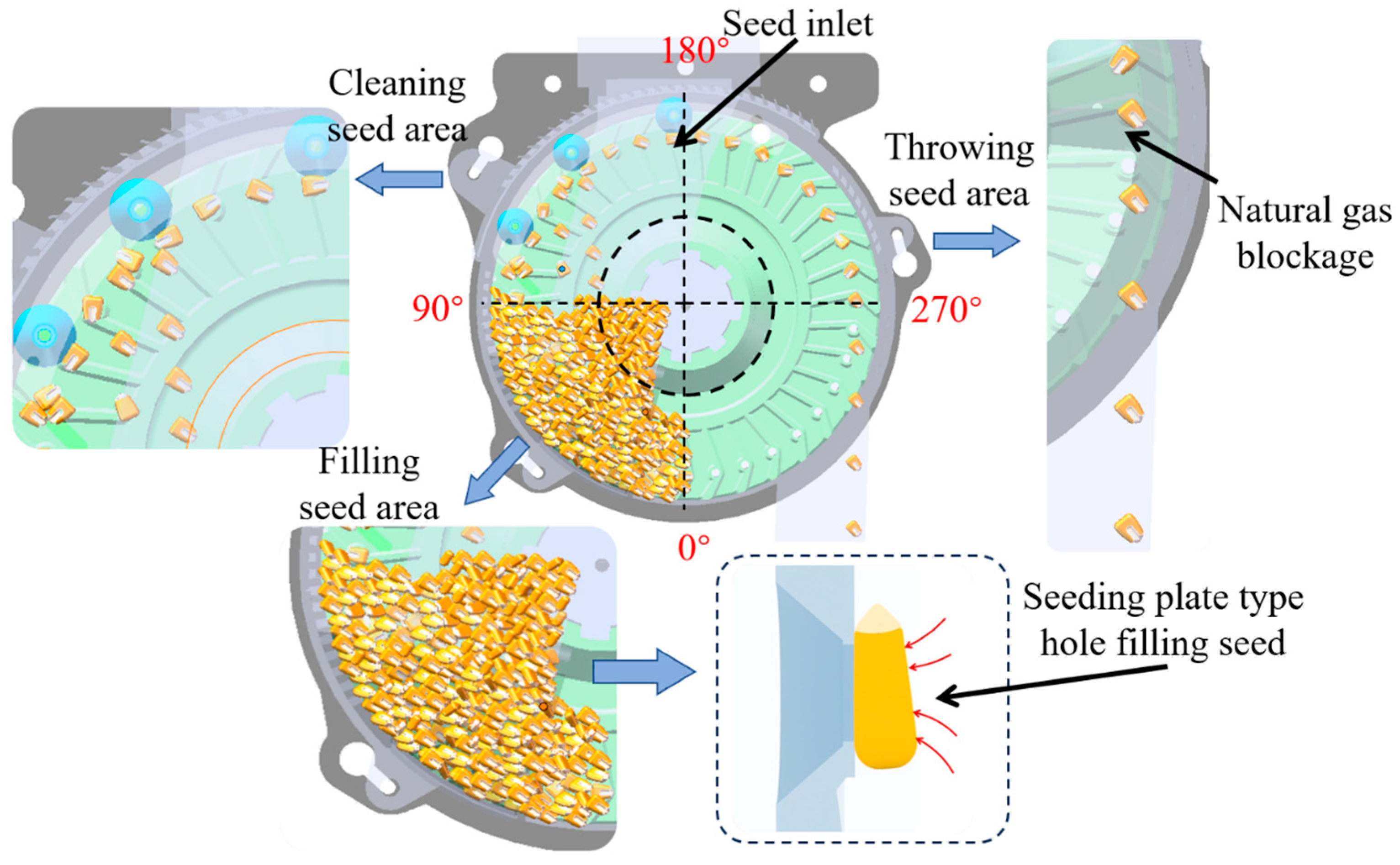
2.2. Working Principle of the Dual-Side-Disturbance-Facilitated Air-Suction Precision Seed Metering Device

The seed metering device is divided into four areas: the filling area, cleaning area, seed-holding area, and seed release area. The angle distribution of each region of the seed metering device is shown in Figure 2. The seed-filling region’s range is (0°, 90°), the seed-cleaning region’s range is (90°, 180°), the seed-carrying region’s range is (180°, 270°), and the seed-dispensing region’s range is (270°, 360°). In the filling area, seeds fall into the seed-filling zone inside the casing. During operation, the motor drives the seed disc to rotate through the drive shaft and the seed disc connection fixture. A negative pressure is generated in the airflow channels by the fan. The disruption grooves on the seed disc guide the seeds towards the suction holes. Under the combined effects of seed gravity, the disruption groove’s force, the inter-seed squeezing pressure, and the negative pressure in the chamber, the seeds are adsorbed into the seed holes. As the seed disc rotates, the seeds detach from the seed population and are subjected to further disturbance by the disruption grooves, which generates a seed-refilling effect and improves seed filling in the seed disc. Next, as the seed disc continues to rotate, the seeds move into the cleaning area. Any excess seeds that are still adhered to the seed holes are removed by the flexible multi-position cleaning wheels, ensuring that only one seed remains in each seed hole. The position of the single seed is adjusted to ensure it is more effectively held by the seed hole. The excess seeds removed by the cleaning mechanism fall back into the filling area due to gravity and are refilled. In the seed holding area, the seeds are stably held on the suction holes. Then, the seeds move with the seed disc into the seed release area. The seeding method adopted here is the airflow-blocking seed release technique. When the airflow-blocking plate isolates the negative pressure, the seeds are released directly into atmospheric pressure and fall down through the seed guiding tube under the effect of gravity.
However, currently, air-assisted seeders tend to have a poor seed-filling quality during high-speed operations. The main reason for this is that maize seeds tend to accumulate inside the seed box, leading to poor flowability. To improve the flowability of seeds in the seed-filling area, dual-side flow guide grooves are used to disturb and promote seed filling, enhancing the seed flowability and thereby improving the seed-filling quality of the seeder.

3. Analysis of the Dual-Side-Disturbance Seed-Filling Principle

The seed disc is a key component that separates seeds from the seed mass and transports them to the sowing area. It directly affects the seed-filling quality. In this design, a dual-side-disturbance seed-filling structure is adopted, with flow guide grooves arranged along the circumference of the seed disc. These grooves guide the seeds into the effective range of the suction holes, disturb the seed mass, and reduce seed-filling resistance. The flow guide grooves and disturbance protrusions are arranged in reverse directions, creating a seed backflow, which expands the seed-filling area and prolongs the seed-filling time. The dual-side flow guide grooves provide dual disturbances, further increasing seed agitation and enhancing seed-filling quality, as shown in Figure 3.
After the maize seeds enter the seed-filling area, seeds that are closer to the suction holes experience a stronger atmospheric suction force and are more easily drawn into the holes. Seeds farther from the suction holes, however, are difficult to move toward the holes due to their own weight, inter-seed resistance, and frictional forces, resulting in a poor seed-filling quality. Among them, the upper-side flow guide groove can guide maize seeds above the suction hole toward the center of the suction hole, while the lower-side flow guide groove can guide maize seeds below the suction hole toward the center as well, achieving dynamic backflow of the seed mass.

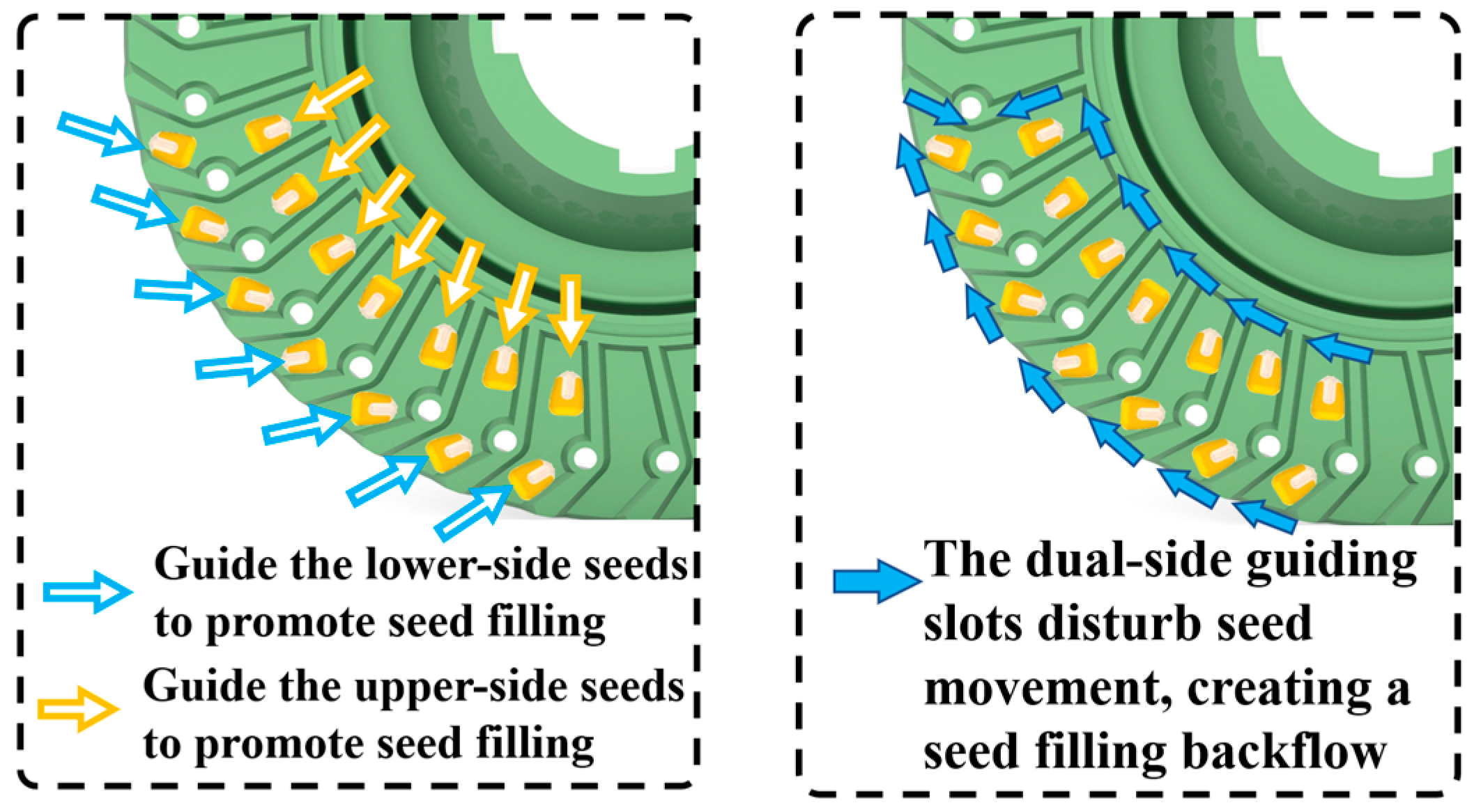
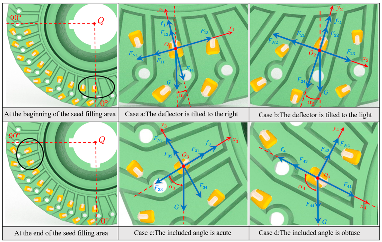
3.1. Analysis of the Disruption-Assisted Filling by the Upper Guiding Groove

To explore the optimal tilt angle for the upper guiding groove’s disruption-assisted filling, a mechanical analysis of the corn seed-filling process is conducted. When the upper guiding groove first enters the filling area and tilts to the right, assume that the angle between the upper guiding groove and the vertical direction is 1°. Taking the centroid O1 of the corn seed on the upper guiding groove as the origin of coordinates, the direction perpendicular to the upper guiding groove is defined as the X1-axis, and the direction parallel to the upper guiding groove is the Y1-axis. A new coordinate system X1O1Y1 is then established, as shown in Figure 4, Case a.
Disregarding the effect of friction on the equivalent torque of the maize seeds, the frictional force acting on the maize seeds is translated to the seed’s center of mass. For the maize seeds in the upper-side flow guide groove, as shown in Figure 4, Case a, a force analysis is conducted, yielding the following:
G sin α + F 11 + F N 1 F 13 = m a 1 G cos α + F 14 f 1 F 12 = m a 2
Among them,
f 1 = μ F 13 F 11 F N 1
In the equation, the variables are defined as follows: G: gravitational force acting on the corn seed, in Newtons (N); α1: angle between the upper guiding groove and the vertical direction, in degrees (°); F11: resultant inter-seed force in the negative direction along the x-axis, in Newtons (N); FN1: normal support force from the guiding groove on the corn seed, in Newtons (N); F13: resultant inter-seed force in the positive direction along the x-axis, in Newtons (N); m: mass of the corn seed, in kilograms (kg); g: acceleration due to gravity, in meters per second squared (m/s2); F14: resultant inter-seed force in the negative direction along the y-axis, in Newtons (N); F12: resultant inter-seed force in the positive direction along the y-axis, in Newtons (N); f1: frictional force acting between the corn seed and the guiding groove, in Newtons (N); μ: coefficient of friction between the corn seed and the guiding groove; a1: acceleration of the corn seed in the negative direction along the x-axis, in meters per second squared (m/s2); a2: acceleration of the maize seed along the negative direction of the y-axis, in m/s2.
Due to the fixed space of the seed box, the force exerted by the population on the corn seeds in the diversion groove can be approximately considered constant, maintaining a state of dynamic equilibrium. Therefore, during the seeding process, the resultant force direction of the corn seeds is along the positive x-axis at one moment and along the negative x-axis at the next moment, indicating that the total resistance among seeds is zero. It can be approximately considered that F11 is equal to F13, and F12 is equal to F14. When the upper diversion groove tilts to the right, the corn seeds do not come into contact with the upper diversion groove, so FN1 equals 0; thus,
G sin α = m a 1 G cos α = m a 2
Therefore, under the influence of its own gravity, the corn seed moves to the bottom of the shell, and the upper diversion groove does not have a guiding effect facilitating the seeding process.
When the maize seed just enters the seed-filling area, and the upper-side flow guide groove tilts to the left, a force analysis for the maize seed in the upper-side flow guide groove is performed, as shown in Figure 4, Case b, yielding the following:
G sin α 2 + F 23 = F N 2 + F 21 G cos α 2 + F 24 = f 2 + F 22
Among them,
f 2 = μ   ( G sin α 2 + F 23 F 21 )
In the equation, α2 represents the angle between the upper diversion groove and the vertical direction (°); F23 is the resultant force of the inter-seed interaction along the positive x-axis, N; FN2 is the supporting force exerted by the upper diversion groove on the corn seeds, N; F21 is the resultant force of the inter-seed interaction along the negative x-axis, N; F24 is the resultant force of the inter-seed interaction along the negative y-axis, N; f2 is the frictional force between the corn seeds and the upper diversion groove, N; and μ is the coefficient of friction between the corn seed and the diversion groove.
To ensure that the upper diversion groove facilitates the seeding process, the following condition must be met:
G cos α 2 + F 24 > μ   ( G sin α 2 + F 23 F 21 ) + F 22
Similarly, the solution can be obtained as follows:
tan α 2 < 1 μ
When substituting μ = 0.337, the calculation yields α2 < 71.3°. This indicates that when the angle between the upper diversion groove and the vertical direction is less than 71.3° upon entering the seeding area, the upper diversion groove has a seeding facilitation effect.
When the maize seed is about to exit the seed-filling area, and the angle between the upper-side flow guide groove and the vertical direction remains acute, a force analysis for the maize seed in the upper-side flow guide groove is performed, as shown in Figure 4, Case c, yielding the following:
G sin α 3 + F 34 = F N 3 + F 32 G cos α 3 + F 33 = f 3 + F 31
Among them,
f 3 = μ   ( G sin α 3 + F 34 F 32 )
Similarly, to ensure that the upper diversion groove facilitates the seeding process, the following condition must be satisfied:
G cos α 3 + F 33 > μ   ( G sin α 3 + F 34 F 32 ) + F 31
In the equation, α3 is the angle between the upper-side flow guide groove and the vertical direction, in degrees (°); F3 is the resultant force of inter-seed interaction along the negative direction of the x-axis, in Newtons (N); FN3 is the support force exerted by the flow guide groove on the maize seed, in Newtons (N); F33 is the resultant force of inter-seed interaction along the positive direction of the x-axis, in Newtons (N); F34 is the resultant force of inter-seed interaction along the negative direction of the y-axis, in Newtons (N); F32 is the resultant force of inter-seed interaction along the positive direction of the y-axis, in Newtons (N); and f1 is the frictional force acting on the maize seed between the flow guide grooves, in Newtons (N).
Similarly, the solution can be obtained as follows:
tan α 3 < 1 μ
When substituting μ = 0.337, the calculation yields α3 < 71.3°. This indicates that when the angle between the upper diversion groove and the vertical direction is less than 71.3° as it is about to leave the seeding area, the upper diversion groove has a seeding facilitation effect.
If the angle between the upper diversion groove and the vertical direction is obtuse when about to exit the seeding area, the corn seeds, influenced by their own gravity and inter-seed forces, will move away from the aperture direction, as shown in case d. In Figure 4, Case d, the upper diversion groove does not facilitate the seeding process.
In summary, to ensure that the upper diversion groove consistently facilitates the seeding process within the seeding area, the following condition must be satisfied.
The inclination angle range of the upper diversion groove is as follows:
α 2 < 71 . 3 ° α 3 < 71 . 3 °
At this point, compared to when it just entered the seeding area, the angle between the upper diversion groove and the vertical direction has rotated by 90°, i.e.,
α 2 + 90 ° = α 3
The solution yields α2 < −18.7°. From case one, it is evident that when α2 is less than 0°, the seeds fall to the bottom of the shell under their own gravity, leading to accumulation. Therefore, the inclination of the upper diversion groove cannot ensure consistent facilitation throughout the seeding area interval (0°, 90°).
If it is chosen that the upper-side flow guide groove does not have a seed-filling effect when the maize seed is about to exit the seed-filling area, this will result in missed sowing, which severely affects the maize yield. If it is chosen that the upper-side flow guide groove does not have a seed-filling effect when the seed just enters the seed-filling area, even if there are suction holes that do not adsorb maize seeds, the seed-filling process can still be completed in the subsequent filling stages. Meanwhile, the maize seeds can move toward the suction holes under the influence of their own gravity, meaning they inherently have a tendency to move toward the suction holes. From Equation (13), it can be derived that when α2 < −18.7°, the upper-side flow guide groove can achieve full-area seed filling in the seed-filling region. Considering the limitations of processing accuracy, the preliminary optimal range for the upper-side flow guide groove’s angle α2 when the seed just enters the seed-filling area is determined to be (−29°, −19°).

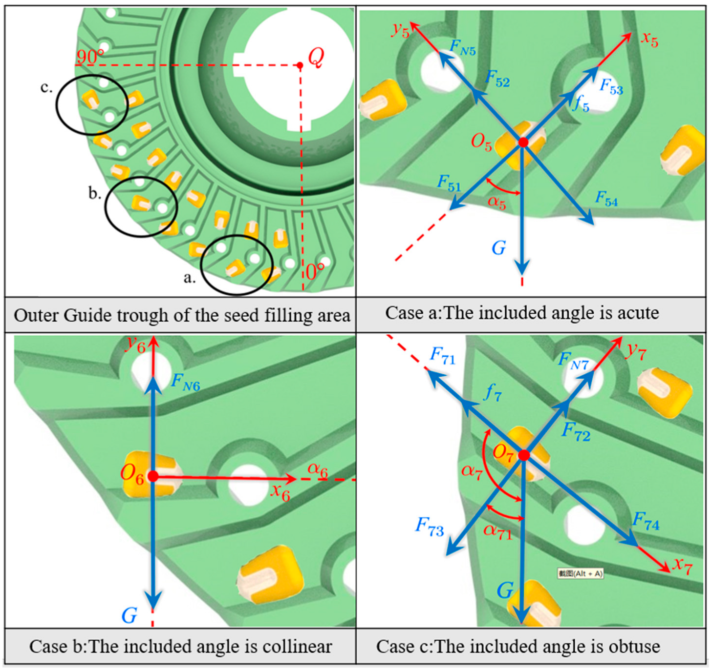
3.2. Analysis of the Disturbance-Facilitated Seeding Effect of the Lower Diversion Groove

When the lower diversion groove is inclined to the left α5 upon entering the seeding area, a force analysis of the corn seeds as they first enter the seeding area is performed, as shown in Figure 5 Case a. The force analysis of the corn seeds at this moment is as follows:
In the x-axis direction,
G cos α 5 + F 51 = f 5 + F 53
In the y-axis direction,
G sin α 5 + F 54 = F N 5 + F 52
Among them,
f 5 =   μ   ( G sin α 5 + F 54 F 52 )
In the equation, G represents the gravity acting on the seed, N; α5 is the angle between the lower diversion groove and the vertical direction (°); F51 is the resultant force of inter-seed interaction along the negative x-axis, N; f5 is the friction force between the corn seed and the diversion groove, N; F53 is the resultant force of inter-seed interaction along the positive x-axis, N; F54 is the resultant force of inter-seed interaction along the negative y-axis, N; FN5 is the supporting force exerted by the diversion groove on the corn seed, N; F52 is the resultant force of inter-seed interaction along the positive y-axis, N; and μ is the coefficient of friction between the corn seed and the lower diversion groove.
Due to the fixed space of the seed box, the force exerted by the population on the corn seeds in the diversion groove can be approximately considered constant, maintaining dynamic equilibrium. Therefore, during the seeding process, the resultant force direction of the corn seeds is along the positive x-axis at one moment and along the negative x-axis at the next moment, indicating that the total resistance among seeds is zero. It can be approximately considered that F51 is equal to F53, and F52 is equal to F54
If the corn seeds move away from the direction of the suction holes, the following condition applies:
G cos α 5 + F 51 > f 5 + F 53
The calculation yields
tan α 5 < 1 μ
Substituting μ = 0.337 into the calculation yields α5 < 71.3°, indicating that corn seeds move away from the aperture direction when this condition is met. Therefore, to prevent corn seeds from moving away from the aperture direction and to enhance the seeding effect, the following condition must be satisfied: α5 ≥ 71.3°.
When the lower diversion groove is in a horizontal position, the force analysis is as shown in Figure 5 Case b, and it does not facilitate the seeding process.
As the lower diversion groove is about to leave the seeding area, a force analysis is performed, as shown in Figure 5 Case c. Conducting a force analysis yields the following:
G sin α 71 + F 74 = F 71 + f 7 G cos α 71 + F 73 = F N 7 + F 72
Among them,
f 7 = μ   ( G cos α 71 + F 73 F 72 )
To ensure that the lower diversion groove facilitates the seeding process at this point, the following condition must be satisfied:
G sin α 71 + F 74 > μ   ( G cos α 71 + F 73 F 72 ) + F 71
In the equation, α7 is the angle between the lower-side flow guide groove and the vertical direction, in degrees (°); α71 is the angle between the vertical direction of the lower-side flow guide groove and the vertical direction, in degrees (°); F71 is the resultant force of inter-seed interaction along the negative direction of the x-axis, in Newtons (N); f7 is the frictional force acting on the maize seed between the flow guide grooves, in Newtons (N); F73 is the resultant force of inter-seed interaction along the positive direction of the x-axis, in Newtons (N); F74 is the resultant force of inter-seed interaction along the negative direction of the y-axis, in Newtons (N); F72 is the resultant force of inter-seed interaction along the positive direction of the y-axis, in Newtons (N); and FN7 is the support force exerted by the flow guide groove on the maize seed, in Newtons (N).
The solution yields the following:
When α7 > 108.6°, the lower diversion groove facilitates the seeding process.
If the lower diversion groove tilts to the right as the corn seeds enter the seeding area, the seeds will not come into contact with the groove. Under their own gravity, the corn seeds will move away from the aperture direction, and the lower diversion groove will not facilitate the seeding process. As the seed metering plate rotates, if the lower diversion groove is initially tilted to the right upon entering the seeding area, it will not reach a horizontal position due to the 90° interval of the seeding area, thereby failing to facilitate the seeding process.
In summary, when the lower diversion groove tilts to the left, to maximize the effective seeding area while ensuring that corn seeds in the non-facilitating region do not tend to move away from the suction holes, the following condition must be satisfied:
α 5 71.3 ° 108.6 ° < α 7 < 180 °
From the geometric relationship, it is known that α7 = α5 + 90°. According to equation (22), the range of α5 is [71.3°, 90°]. Considering the limitations of processing accuracy, the initial optimal range for the lower guiding groove inclination angle α5 in the seed-filling area is determined to be (72°, 90°).

3.3. Parameter Design of the Seed Metering Disc

The diameter is a fundamental structural parameter of the seed disc, directly affecting the overall size of the seed metering device. A larger diameter allows for the design of more apertures, enabling a greater seeding rate at the same rotational speed, and under a fixed plant spacing, it can increase the operating speed. However, an excessively large diameter increases the size of the seed metering device, raises manufacturing costs, and may lead to installation difficulties. On the other hand, a diameter that is too small would limit the number of apertures that can be designed, failing to meet the seeding requirements for small plant spacing and dense planting. The seed disc diameter is designed to be 238 mm [26].
The number of suction holes in the seed disc is a crucial factor affecting the seeding quality of the device. An excessive number of suction holes can lead to seed collisions, resulting in a decreased qualification rate. Conversely, too few suction holes require an increase in the rotational speed of the seed disc under the same sowing conditions, reducing the seed-filling time and negatively impacting the seed-filling quality. The number of apertures is designed to be 35, with a suction hole diameter of 4.6 mm, and the seed disc thickness is designed to be 2.5 mm [27]. The material chosen for the seed disc is photosensitive resin, and the processing method is photopolymerization.

4. Experiments and Methods

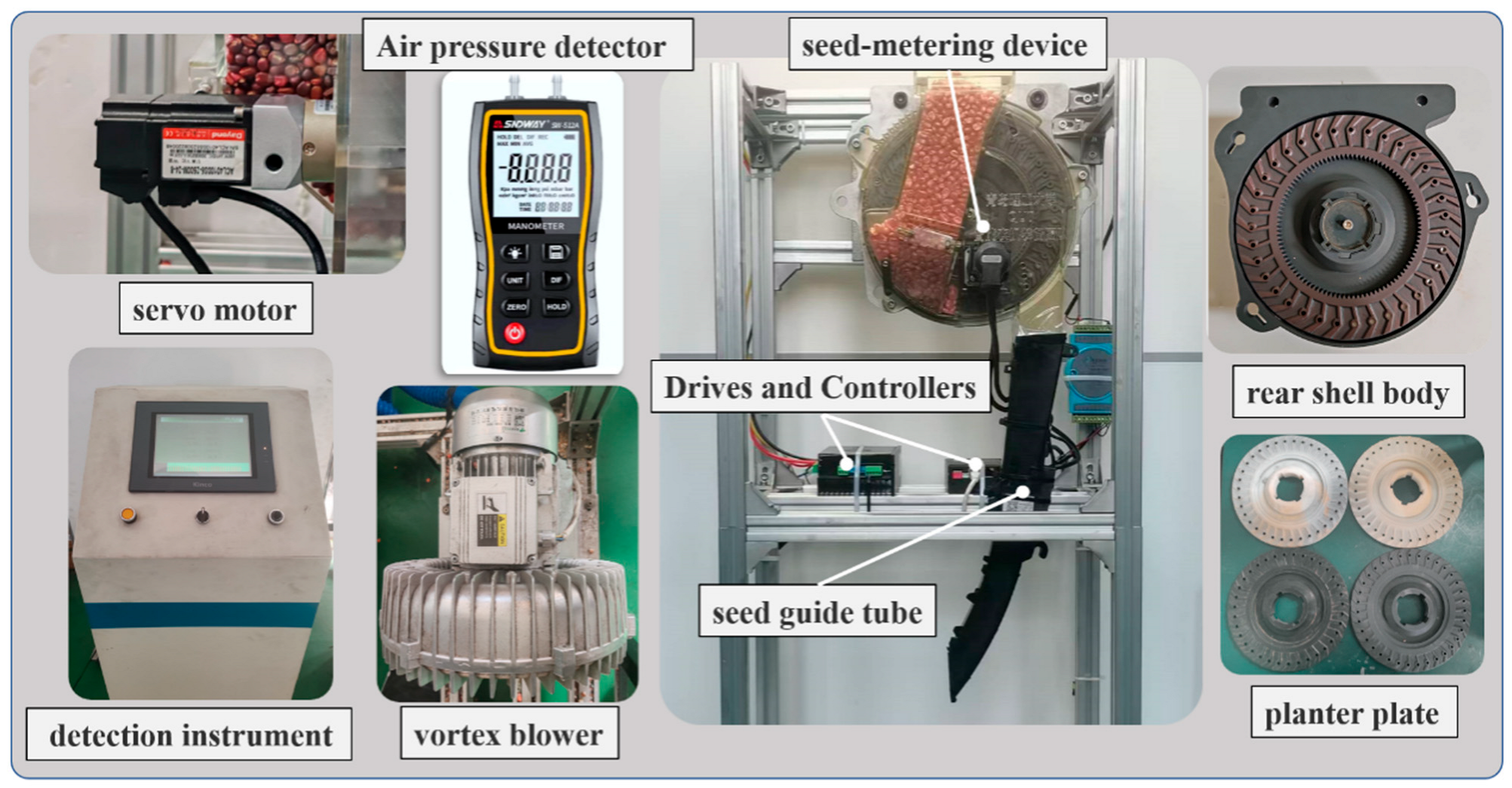
4.1. Test Bench Equipment

The experiment used ungraded Zhengdan 958 maize seeds with a 1000-grain weight of 290.2 g and a moisture content of 10.36%. The test setup, as shown in Figure 6, primarily includes the seed performance testing device, fan, aluminum profile frame, pressure measurement device, motor drive, and the dual-side-disturbance-promoting pneumatic seed metering device. During operation, the seeds ejected by the dual-side-disturbance-promoting pneumatic seed metering device fall into the seed guide tube. The infrared sensor inside the seed guide tube collects the seed placement data and transmits them to the seed metering performance testing device terminal, which calculates and displays the qualification index, missing seeding index, and double seeding index.

4.2. Experimental Design

(1)
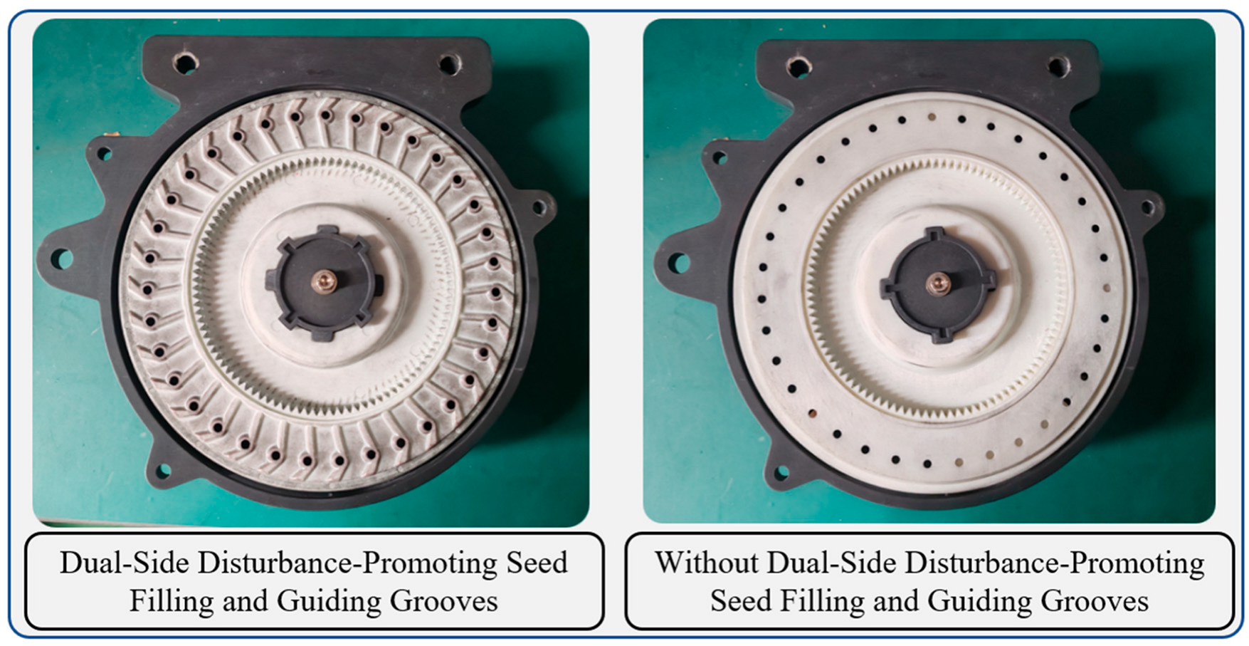
A Box–Behnken orthogonal bench test is conducted to analyze the effects of various experimental factors and their interactions on the qualification index, missing seeding index, and double seeding index of the seed metering device. This approach aims to accurately determine the optimal parameter combination for the negative suction chamber pressure and the inclination angles of the dual-side guiding grooves. The experimental coding is shown in Table 1 (operating speed: 12 km/h). The guiding slots on the upper and lower sides with different angles are manufactured using 3D photopolymerization technology, with photosensitive resin as the material, as shown in Figure 7.
(2)
Based on the optimal parameter combination, adaptability tests for the operating speed were conducted to evaluate the seeding performance of the dual-side-disturbance seed-filling air-assisted precision seeder under operating speeds of 8, 10, 12, 14, and 16 km/h.
(3)
Comparative tests were conducted under operating speeds of 8–12 km/h between the seed metering devices with and without dual-side-facilitated diversion grooves to verify the superior seeding quality of the dual-side-disturbance seed-filling air-assisted precision seeder.

4.3. Test Metrics

According to the agronomic requirements for the planting of the Zhengdan 958 corn variety, the planting spacing Z was set to 25 cm, and the operating speeds were 12, 14, and 16 km/h. Each group of tests was repeated three times, and the average value was taken as the test result. The evaluation metrics selected included the qualified index, missed seeding index, and double seeding index. Plant spacing within 0.5 Z ≤ Xi ≤ 1.5 Z was considered qualified, spacing greater than 1.5 Z was considered missed seeding, and spacing less than 0.5 Z was considered double seeding. The calculation formulas are shown in Equation (23).
A = n 1 N × 100 % M = n 2 N × 100 % D = n 3 N × 100 %
In the formulas, A represents the qualified index (%); n1 is the number of qualified plant spacings; N is the total number of measured plant spacings; M represents the missed seeding index (%); n2 is the number of missed plant spacings; D represents the double seeding index (%); and n3 is the number of double plant spacings.

5. Experimental Results and Discussion

5.1. Box–Behnken Orthogonal Test

5.1.1. Statistical Analysis of Test Results

We performed design and analysis of the experiment based on the Box–Behnken experimental principle, with a total of 17 experimental points [28,29,30,31]. The experimental results are shown in Table 2.

5.1.2. Establishment of Regression Models and Significance Tests

Using Design-Expert 13 software, a multivariate regression fitting analysis was performed on the test results to establish response surface regression models for Y1, Y2, and Y3 with respect to X1, X2, and X3.
Y 1 = 97.12 0.525 X 1 0.525 X 2 0.55 X 3 0.275 X 1 X 2 0.075 X 1 X 3   + 0.225 X 2 X 3 1.77 X 1 2 0.6225 X 2 2 0.0725 X 3 2 Y 2 = 1.48 + 0.3 X 1 + 0.2125 X 2 + 0.2125 X 3 0.125 X 1 X 2 0.075 X 1 X 3   + 0.05 X 2 X 3 + 1.21 X 1 2 + 0.185 X 2 2 + 0.085 X 3 2 Y 3 = 1.4 + 0.225 X 1 + 0.3125 X 2 + 0.3375 X 3 + 0.4 X 1 X 2 + 0.15 X 1 X 3   0.275 X 2 X 3 + 0.5625 X 1 2 + 0.4375 X 2 2 0.0125 X 3 2
The variance analysis of the regression equation is shown in Table 3, Table 4 and Table 5.
In Table 3, Table 4 and Table 5, the p-values for the qualified index Y1, missed seeding index Y2, and double seeding index Y3 are <0.0001, <0.0001, and 0.0004, respectively, indicating that all three models have highly significant effects. The p-values of the lack-of-fit terms are 0.0958, 0.1591, and 0.5413 (all greater than 0.05), indicating a high degree of fit for the three models. The coefficients of determination R2 are 0.9634, 0.9568, and 0.9075, respectively, showing that more than 90% of the response values can be explained by these models. Therefore, these models can be used to predict the operating parameters of the dual-side-disturbance-facilitated air-suction seed metering device.

5.1.3. Response Surface Analysis of the Effects of Significant Interaction Factors on Performance Indicators

Based on the test results, the impacts of the negative working pressure X1, upper diversion groove inclination angle X2, and lower diversion groove inclination angle X3 on the performance indicators were analyzed. Using Design-Expert software, response surfaces were plotted to show the effects of significant interaction factors on the qualified index Y1, missed seeding index Y2, and double seeding index Y3.
As shown in Figure 8a, the qualified index initially increases and then decreases with the increase in negative suction chamber pressure. The reason is that when the negative suction chamber pressure is low, the seeding effect is poor, leading to a higher missed seeding index and consequently a lower qualified index. However, as the negative pressure further increases, the “over-suction” phenomenon occurs, causing the double seeding index to rise, which also reduces the qualified index. The interaction between the negative suction chamber pressure and the upper diversion groove inclination angle significantly affects the qualified index.
As shown in Figure 8b, the double seeding index initially decreases and then increases with the increase in negative suction chamber pressure. This is because, at a higher negative pressure, corn seeds located at the center of the suction holes are easily adsorbed, while seeds on the edges fall into the seeding area under gravity and inter-seed forces, reducing the double seeding index. However, as the negative pressure continues to increase, seeds on the edges are also adsorbed into the suction holes, causing the double seeding index to rise. The interaction between the negative suction chamber pressure and the upper diversion groove inclination angle has a highly significant impact on the double seeding index.
As shown in Figure 8c, the double seeding index increases with the increase in the upper diversion groove inclination angle. This is because a larger inclination angle creates a larger facilitation zone in the upper diversion groove, leading to an increase in the double seeding index. Similarly, the double seeding index also increases with the increase in the lower diversion groove inclination angle, as a larger inclination angle in the lower diversion groove also results in a larger facilitation zone. The interaction between the upper and lower diversion groove inclination angles significantly affects the double seeding index.

5.1.4. Parameter Optimization and Validation Test

Based on the mathematical models for the qualified index Y1, missed seeding index Y2, and double seeding index Y3, the optimal parameter combination for the seed metering device can be selected within the constraint conditions and validated.
Taking the maximum qualified index Y1, minimum missed seeding index Y2, and minimum double seeding index Y3 as evaluation criteria, an optimization mathematical model is established as follows:
max Y 1 X 1 , X 2 , X 3 min Y 2 X 1 , X 2 , X 3 min Y 3 X 1 , X 2 , X 3 s . t . 1 X 1 1 1 X 2 1 1 X 3 1
The optimal parameter combination was determined using Design-Expert software, which is as follows: a negative suction chamber pressure of 3.72 kPa, upper-side guiding slot angle of −26.85°, and lower-side guiding slot angle of 72.85°. The corresponding qualification index is 97.72%, the missed sowing index is 1.29%, and the double sowing index is 0.99%. Due to machining errors, achieving the theoretical optimization values is challenging. Therefore, a set of practical working parameters close to the theoretical values was selected for validation tests: a negative suction chamber pressure of 3.7 kPa, upper diversion groove inclination angle of −26.9°, and lower diversion groove inclination angle of 72.9°. The tests were repeated three times, and the average results showed a qualified index of 97.7%, a missed seeding index of 1.3%, and a double seeding index of 1%.

5.2. Operating Speed Adaptability Test

To verify the adaptability of the dual-side-disturbance seed-filling air-assisted precision seeder to different operating speeds under the optimal parameter combination, an operating speed adaptability test was conducted. Under the optimal parameters (negative suction chamber pressure of 3.7 kPa, upper diversion groove inclination angle of −26.9°, and lower diversion groove inclination angle of 72.9°), the seeding performance of the device was tested at operating speeds of 8, 10, 12, 14, and 16 km/h. The test results are shown in Table 6. Since the plant spacing for corn and the number of seed suction holes in the seed disc are predetermined, the rotational speed of the seed disc is proportional to the operating speed. The operating speed can be controlled by adjusting the motor speed.
The test results indicate that when the operating speed is ≤14 km/h, the seed metering device achieves a qualified index of over 97.1%, a missed seeding index below 1.5%, and a double seeding index below 1.4%. This demonstrates that the seed metering device has good adaptability to the operating speed.

5.3. Comparative Test

To verify the superior seeding quality of the seed metering device equipped with dual-side-facilitated diversion grooves, comparative tests were conducted under operating speeds of 8 to 12 km/h with a seed metering device that does not have dual-side-facilitated diversion grooves. The experimental results are shown in Table 7. The seed disc with guiding slots and the seed disc without guiding slots are shown in Figure 9.
The comparison experiment results indicate that when the working speed is between 8 and 12 km/h, the gas-assisted seeder with dual-side-disturbance seed-filling flow guide grooves shows an increase of more than 2.1% in the qualification index. The seed-filling quality of the gas-assisted seeder with dual-side-disturbance seed-filling flow guide grooves is significantly improved.

5.4. Energy Consumption Comparison Test

To verify the energy-saving and emission reduction advantages of the dual-side-disturbance-facilitated air-suction seed metering device with dual-side guiding slots, an energy consumption comparison test was conducted with a conventional pneumatic seed metering device without dual-side guiding slots. Under the working speed range of 8–12 km/h, the required air pressure for both seed metering devices to achieve a qualification index close to standard is shown in Table 8.
The energy consumption comparison test results show that under the same operating speed conditions, when the qualification index is approximately the same, the dual-side-disturbance-facilitated air-suction seed metering device with dual-side guiding slots requires a reduction of more than 0.7 kPa in negative pressure, effectively reducing energy consumption.

6. Conclusions

(1)
To address the issue of poor seed filling and a decreased sowing quality in air-assisted seeders during high-speed operation, a dual-side flow guide groove disturbance seed-filling air-assisted seeder was designed. The main structure and working principle of the seeder were introduced, and a theoretical analysis of the optimal angles of the dual-side flow guide grooves was conducted. The optimal range for the upper-side flow guide groove angle was found to be −29° to −19°, and for the lower-side flow guide groove, it was 72° to 90°.
(2)
The validation experimental results showed that when the negative suction chamber pressure was 3.7 kPa, the upper-side flow guide groove angle was −26.9°, and the lower-side flow guide groove angle was 72.9°, the experimental results were as follows: the qualification index was 97.7%, missed seeding index was 1.3%, and double seeding index was 1%. The working speed adaptability test showed that when the working speed was ≤14 km/h, the seeder’s qualification index was above 97.1%, the missed seeding index was below 1.5%, and the double seeding index was below 1.4%. The seeder demonstrated good adaptability to operating speeds. The comparative experimental results indicated that when the operating speed was between 8 and 12 km/h, the air-assisted seeder with dual-side-disturbance seed-filling flow guide grooves had an increase of more than 2.1% in the qualification index, demonstrating a superior seed-filling quality. The energy consumption comparative test results show that under the same operating speed conditions, when the qualification index is approximately the same, the dual-side-disturbance-facilitated air-suction seed metering device with dual-side guiding slots requires a reduction of more than 0.7 kPa in negative pressure, effectively reducing energy consumption.

Author Contributions

Writing—original draft preparation, F.Y.; writing—review and editing, Q.S.; supervision, Y.L. and S.C.; collection and organization of experimental data, B.L.; investigation, S.Z. All authors have read and agreed to the published version of the manuscript.

Funding

This research was funded by the National Natural Science Foundation of China, grant number 52202508, the Science and Technology Planning Project of Xinjiang Production and Construction Corps, grant number 2024AB047, and Shandong Provincial Natural Science Foundation Youth, grant number ZR2022QE231. The Central Government-Guided Local Science and Technology Development Fund Project, grant number 2024YD012.

Institutional Review Board Statement

Not applicable.

Data Availability Statement

The data presented in this study are available on request from the corresponding author.

Acknowledgments

The authors are grateful to the anonymous reviewers for their comments.

Conflicts of Interest

The authors declare no conflicts of interest.

References

  1. Tang, H.; Guan, T.Y.; Xu, F.D.; Xu, C.S.; Wang, G.W. Test on adsorption posture and seeding performance of the high-speed precision dual-chamber maize metering device based on the seed characteristics. Comput. Electron. Agric. 2024, 216, 108471. [Google Scholar] [CrossRef]
  2. Nikolay, Z.; Nikolay, K.; Gao, X.J.; Li, W.Q.; Mi, G.P.; Huang, Y.X. Design and testing of novel seed miss prevention system for single seed precision metering devices. Comput. Electron. Agric. 2022, 198, 107048. [Google Scholar] [CrossRef]
  3. Pareek, C.M.; Tewari, V.K.; Machavaram, R. Multi-objective optimization of seeding performance of a pneumatic precision seed metering device using integrated ANN-MOPSO approach. Eng. Appl. Artif. Intell. 2023, 117, 105559. [Google Scholar] [CrossRef]
  4. Zhai, J.B.; Xia, J.F.; Zhou, Y.; Zhang, S. Design and experimental study of the control system for precision seed-metering device. Int. J. Agric. Biol. Eng. 2014, 7, 13–18. [Google Scholar] [CrossRef]
  5. Wang, J.W.; Qi, X.; Xu, C.S.; Wang, Z.M.; Jiang, Y.M.; Tang, H. Design evaluation and performance analysis of the inside-filling air-assisted high-speed precision maize seed-metering device. Sustainability 2021, 13, 5483. [Google Scholar] [CrossRef]
  6. Weirich Neto, P.H.; Justino, A.; Namur, R.T.; Domingues, J.; Garcia, L.C. Comparison of metering mechanisms of corn seed. Eng. Agrícola 2012, 32, 981–988. [Google Scholar] [CrossRef]
  7. Wen, C.K.; Zhang, J.; Zheng, K.; Li, H.Q.; Ling, L.; Meng, Z.J.; Fu, W.Q.; Yan, B.X. Accelerated verification method for the reliability of the motor drive mechanism of the corn precision seed-metering device. Comput. Electron. Agric. 2023, 212, 108163. [Google Scholar] [CrossRef]
  8. Li, J.H.; Lai, Q.H.; Zhang, H.; Zhang, Z.G.; Wang, T.T. Suction force on high-sphericity seeds in an air-suction seed-metering device. Biosyst. Eng. 2021, 211, 125–140. [Google Scholar] [CrossRef]
  9. Shi, L.R.; Zhao, W.S.; Sun, W.; Yang, X.P.; Wang, G.P.; Xin, S.L. Analysis of the metering performance for typical shape maize seeds using DEM. Int. J. Agric. Biol. Eng. 2023, 16, 26–35. [Google Scholar] [CrossRef]
  10. Wang, Y.X.; Zhang, W.Y.; Qi, B.; Ding, Y.Q.; Xia, Q.Q. Research on Control System of Corn Planter Based on Radar Speed Measurement. Agronomy 2024, 14, 1043. [Google Scholar] [CrossRef]
  11. Zhao, X.J.; Zhao, H.P.; Wang, Z.H.; Li, J.C.; Yu, H.; Yan, Q. Electronic control seed-metering system for precision seeding maize based on fuzzy PID. Int. J. Agric. Biol. Eng. 2024, 17, 217–226. [Google Scholar] [CrossRef]
  12. Liao, Y.Y.; You, Y.; Hui, Y.T.; Zhang, X.N.; Wang, D.C. Mixed Seeds of Oat and Vetch Based on DEM-Fluent Coupling Motion Simulation in a Venturi Tube. Processes 2023, 11, 1095. [Google Scholar] [CrossRef]
  13. Zhang, C.L.; Zhang, X.Y.; Zheng, Z.H.; Xie, X.D.; Liu, L.C.; Chen, L.Q. Numerical Simulation and Test of the Disturbance Air Suction Garlic Seed Metering Device. Machines 2022, 10, 1127. [Google Scholar] [CrossRef]
  14. Dizaji, H.Z.; Taheri, M.R.Y.; Minaei, S. Air-jet seed knockout device for pneumatic precision planters. AMA-Agric. Mech. Asia Afr. Lat. Am. 2010, 41, 45–50. [Google Scholar]
  15. Li, C.; Zhang, D.X.; Yang, L.; Cui, T.; He, X.T.; Li, Z.M.; Xing, S.L.; Jiang, Y.Y.; Liang, J.Y. Research on a centrifugal high-speed precision seed metering device for maize with airflow-assisted seed filling and cleaning. Comput. Electron. Agric. 2024, 226, 109434. [Google Scholar] [CrossRef]
  16. Guo, J.; Yang, Y.; Memon, M.S.; Tan, C.; Wang, L.Y.; Tang, P. Design and simulation for seeding performance of high-speed inclined corn metering device based on discrete element method (DEM). Sci. Rep. 2022, 12, 19415. [Google Scholar] [CrossRef]
  17. Shah, K.; Alam, M.S.; Nasir, F.E.; Muhammad, U.Q.; Izhar, U.H.; Muhammad, T.K. Design and performance evaluation of a novel variable rate multi-crop seed metering unit for precision agriculture. IEEE Access 2022, 10, 133152–133163. [Google Scholar] [CrossRef]
  18. Xiong, D.Y.; Wu, M.L.; Xie, W.; Liu, R.; Luo, H.F. Design and experimental study of the general mechanical pneumatic combined seed metering device. Appl. Sci. 2021, 11, 7223. [Google Scholar] [CrossRef]
  19. Li, D.; Ye, C.Y.; Yu, F.D.; Chen, X.L.; Zhan, H.; Guang, M.G.; Yi, D. Design and Experiment of Air-Suction Maize Seed-Metering Device with Auxiliary Guide. Agriculture 2024, 14, 169. [Google Scholar] [CrossRef]
  20. Wang, Y.; Kang, X.; Wang, G.; Ji, W.Y. Numerical Analysis of Friction-Filling Performance of Friction-Type Vertical Disc Precision Seed-Metering Device Based on EDEM. Agriculture 2023, 13, 2183. [Google Scholar] [CrossRef]
  21. Bereket, B.Z. Effect of different operating parameters on seed holding in the single seed metering unit of a pneumatic planter. Turk. J. Agric. Mach. 2024, 28, 435–441. [Google Scholar]
  22. Pareek, C.M.; Tewari, V.K.; Machavaram, R.; Nare, B. Optimizing the seed-cell filling performance of an inclined plate seed metering device using integrated ANN-PSO approach. Artif. Intell. Agric. 2021, 5, 1–12. [Google Scholar] [CrossRef]
  23. Wang, D.W.; Ji, R.Q.; He, X.N.; Guo, P.; Shi, Y.X.; Zhang, C.X. Drive-guided Combination Slot-assisted Seed-attached Air-absorbing Peanut High-speed Precision Seed Meter. Trans. Chin. Soc. Agric. Mach. 2023, 54, 59–70+149. [Google Scholar]
  24. Ding, L.; Yang, L.; Liu, S.R.; Yan, B.X.; He, X.T.; Zhang, D.X. Design of air suction high speed precision maize seed metering device with assistant seed filling plate. Trans. Chin. Soc. Agric. Eng. 2018, 34, 1–11. [Google Scholar]
  25. Karayel, D.; Güngör, O.; Šarauskis, E. Estimation of optimum vacuum pressure of air-suction seed-metering device of precision seeders using artificial neural network models. Agronomy 2022, 12, 1600. [Google Scholar] [CrossRef]
  26. Ghanshyam, P.; Raghunandan, S.; Navneet, K. Evaluation of Physical Properties of Maize and Pigeonpea Seeds for Seed Metering Mechanism. J. Exp. Agric. Int. 2023, 45, 89–97. [Google Scholar] [CrossRef]
  27. Li, C.; Cui, T.; Zhang, D.X.; Yang, L.; He, X.T.; Jing, M.S. Design shaped hole inserts by simulating and analysing the high-speed filling posture of maize seed particles. J. Biosyst. Eng. 2023, 232, 29–50. [Google Scholar] [CrossRef]
  28. Huang, Y.; Li, P.; Dong, J.X.; Chen, X.H.; Zhang, S.L.; Liu, Y. Design and Experiment of Side-mounted Guided High Speed Precision Seed Metering Device for Soybean. Trans. Chin. Soc. Agric. Mach. 2022, 53, 44–53. [Google Scholar]
  29. Hou, S.Y.; Zou, Z.; Wei, Z.P.; Zhu, Y.F.; Chen, H.T. Design and Experiment of Flexible Mechanical Soybean Precision Seed-metering Device. Trans. Chin. Soc. Agric. Mach. 2020, 51, 77–86+108. [Google Scholar]
  30. Zhang, F.X.; Qin, C.L.; Wang, X. Study on Leak in Seeding Prevention and Seed Protection of Disc Precision Soybean Metering Device. J. Agric. Mech. Res. 2022, 44, 65–70. [Google Scholar]
  31. Chen, M.Z.; Diao, P.S.; Zhang, Y.P.; Gao, Q.M.; Yang, Z.; Yao, W.Y. Design of single-disk double-row air-aspirated seed discharger for soybean narrow-row dense-planting planter. J. Agric. Eng. 2018, 34, 8–16. [Google Scholar]
Figure 1. Double-side disturbance, seed-promoting, inflation, suction, high-speed precision seeder.
Agriculture 15 00763 g001
Figure 2. Air-assisted high-speed precision seed metering device.
Agriculture 15 00763 g002
Figure 3. Schematic diagram of the working principle of the dual-side-disturbance seed-filling air-assisted precision seeder.
Agriculture 15 00763 g003
Figure 4. Schematic diagram of the mechanical analysis of the upper-side-disturbance seed-filling force.
Agriculture 15 00763 g004
Figure 5. Schematic diagram of the force analysis of the lower-side flow guide groove.
Agriculture 15 00763 g005
Figure 6. Schematic diagram of bench test.
Agriculture 15 00763 g006
Figure 7. Diversion grooves with varying inclination angles.
Agriculture 15 00763 g007
Figure 8. Response surface diagram of the impact of significant interaction factors on performance indicators.
Agriculture 15 00763 g008
Figure 9. Comparative schematic diagram of seed discs with dual-side guiding slots and those without.
Agriculture 15 00763 g009
Table 1. Experimental factor coding for the dual-side-disturbance seed-filling air-assisted precision seeder.
CodeFactor
Negative Pressure
X1 (kPa)
Upper Flow Guide Slot Inclination Angle X2 (°)Lower Flow Guide
Slot Inclination
Angle X3 (°)
−13−2972
04−2481
15−1990
Table 2. Test results.
Serial NumberTest FactorsTest Metrics
X1X2X3Qualification Index Y1Missed Seeding Index Y2Double Seeding
Index Y3
15−198193.43.33.3
24−248197.21.31.5
33−298195.52.22.3
44−248197.31.61.1
55−247295.52.81.7
64−197296.11.82.1
74−299096.31.62.1
85−298195.13.11.8
94−248197.11.51.4
105−249093.93.32.8
113−249095.22.91.9
123−247296.52.11.4
134−199095.82.12.1
144−248196.91.51.6
154−297297.51.51
164−248197.11.51.4
173−198194.92.92.2
Table 3. Analysis of variance for the qualification index regression equation.
Source of VariationQualification Index Y1
Sum of SquaresDegree of FreedomFp
Model22.93947.81<0.0001
X12.20141.380.0004
X22.20141.380.0004
X32.42145.420.0003
X1X20.302515.680.0487
X1X30.022510.42230.5365
X2X30.202513.800.0922
X1213.231248.26<0.0001
X221.63130.620.0009
X320.022110.41530.5398
Residuals0.37307
Misfitting0.285034.320.0958
error0.08804
sum23.3016
R20.9634
Table 4. Analysis of variance for the missed seeding index regression equation.
Source of
Variation
Missed Seeding Index Y2
Sum of
Squares
Degree of
Freedom
Fp
Model8.08940.39<0.0001
X10.7200132.410.0007
X20.3613116.260.0050
X30.3613116.260.0050
X1X20.062512.810.1374
X1X30.022511.010.3477
X2X30.010010.45020.5238
X126.161277.51<0.0001
X220.144116.490.0383
X320.030411.370.2802
Residuals0.15557
Misfitting0.107532.990.1591
error0.04804
sum8.2316
R20.9568
Table 5. Analysis of variance for the double seeding index regression equation.
Source of
Variation
Double Seeding Index Y3
Sum of
Squares
Degree of
Freedom
Fp
Model5.39918.430.0004
X10.4050112.460.0096
X20.7813124.040.0017
X30.9112128.040.0011
X1X20.6400119.690.0030
X1X30.090012.770.1400
X2X30.302519.310.0186
X121.33140.990.0004
X220.8059124.800.0016
X320.000710.02020.8909
Residuals0.22757
Misfitting0.087530.83330.5413
error0.14004
sum5.6216
R20.9075
Note: 0.01 < p < 0.05 indicates a significant difference. The expression “p < 0.01” represents an extremely significant difference.
Table 6. Operating speed adaptability test results.
Operating SpeedQualified Index/%Missed Seeding
Index/%
Double Seeding
Index/%
899.10.60.3
1098.60.90.5
1297.71.31.0
1497.11.51.4
1695.62.32.1
Table 7. Comparative test results.
Seed Metering DeviceOperating Speeds (km·h−1)Qualified Indexes %
The air-suction seed metering device with dual-side-disturbance-facilitated diversion grooves899.2
1098.5
1297.8
The air-suction seed metering device without dual-side-disturbance-facilitated diversion grooves897.1
1095.5
1294.2
Table 8. Energy consumption comparison test.
Seed Planter TypeOperating Speed
(km·h−1)
Seed-Filling Quality Index
%
Wind Pressure
kPa
Air-suction Seeder with Double-Side Flow Guide Grooves and Double-Side Seed Disturbance897.23.3
1095.53.8
1293.84.2
Conventional Air-Suction Seeder without Double-Side Flow
Guide Grooves
897.34.1
1095.64.5
1293.74.9
Disclaimer/Publisher’s Note: The statements, opinions and data contained in all publications are solely those of the individual author(s) and contributor(s) and not of MDPI and/or the editor(s). MDPI and/or the editor(s) disclaim responsibility for any injury to people or property resulting from any ideas, methods, instructions or products referred to in the content.

