Article

Design of a Seed-Pressing Mechanism for Precision Peanut Planters and Verification of Optimal Operating Parameters Under High-Speed Seeding Conditions

1
College of Mechanical and Electronic Engineering, Shandong Agricultural University, Taian 271018, China
2
College of Mechanical and Electrical Engineering, Qingdao Agricultural University, Qingdao 266109, China
3
Yellow River Delta Intelligent Agricultural Machinery Equipment Industry Academy, Dongying 257300, China
4
School of Ecology and Biology, Dongying Vocational College, Dongying 257300, China
5
National Center of Technology Innovation for Comprehensive Utilization of Saline-Alkali Land, Dongying 257300, China
*
Authors to whom correspondence should be addressed.
Agriculture 2025, 15(21), 2246; https://doi.org/10.3390/agriculture15212246
Submission received: 16 September 2025 / Revised: 22 October 2025 / Accepted: 27 October 2025 / Published: 28 October 2025
(This article belongs to the Section Agricultural Technology)

Abstract

This paper presents the design of a seed-pressing mechanism for a high-speed suction-type precision peanut planter to address the issue of poor seeding performance at high travel speeds and to reduce seed bounce within furrows. To clarify the working principle of the mechanism, a force analysis of peanut seeds in the furrow and a numerical study using discrete element analysis were conducted under high-speed operating conditions. Simulation results show that when the distance between the center of the seed-pressing wheel and the seeding-tube outlet (DCSPW-STO) is 146.11 mm, the seed-pressing wheel diameter is 198.13 mm, and the machine operating velocity is 6.45 km h−1, the plant spacing qualification index and seeding depth compliance index for peanuts planted after rolling reach their maximum values. The corresponding germination rates of 93.78% and 90.65% indicate satisfactory sowing performance. Field validation trials demonstrate that when DCSPW-STO (lfz) is 146 mm, the seed-pressing wheel diameter (dfz) is 198 mm, and the machine operating velocity (v) is 6.45 km h−1, the post-seeding plant-spacing qualification index and the seeding-depth compliance index reach 90.31% and 89.18%, respectively. Although slightly lower than the simulation results, these values meet the operational requirements for peanut seeding. Field performance comparisons with non-pressure seeding units further confirm that units equipped with the seed-pressing and soil-covering mechanisms significantly improve both the plant-spacing qualification index and the seeding-depth compliance index, satisfying agronomic requirements for high-speed peanut cultivation.

1. Introduction

Peanuts are a globally significant oilseed crop and a high-quality raw material for food processing and light industry. The annual planting area exceeds 25.3 million hectares, with annual peanut production surpassing 408.7 million tons [1,2,3,4]. Currently, China primarily uses peanuts for oil extraction and food processing, the United States mainly for peanut butter, and the European Union primarily for direct consumption. As living standards improve, the demand for peanuts continues to increase, leading to a year-on-year expansion of planting areas. This places new demands for precision and efficiency on mechanized precision planting.
An important approach to increasing crop yield per unit area involves the precise control of seeding rates, which requires accurate regulation throughout seed delivery and placement. Precision seeding equipment must therefore ensure accurate seed retrieval, cleaning, transport, dispensing, and placement into the furrow. Precision seeding technology has been widely applied to crops such as wheat, rice, corn, soybeans, and peanuts [5,6,7,8,9,10]. However, due to their limited operational time, traditional seeding methods struggle to effectively increase overall crop yield. Consequently, air-suction seeding has been increasingly adopted. For example, Liu et al. improved seed suction efficiency by analyzing the structural and operational parameters of a suction-type disturbance-assisted seeding structure [11]. Zang et al. enhanced the stability of precision rice seeding by examining the effects of rectangular seed intake holes on the operational performance of air-suction seed dispensers [12]. Ding et al. improved high-speed corn seeding by designing a corn planter equipped with auxiliary guide rails and analyzing its airflow field structure, negative pressure, and airflow volume [13].
During seed placement, seeds are ejected from the seeding-tube outlet, undergo a brief free fall, and then drop into the seed furrow. However, during high-speed seeding, seeds are ejected at high velocity from the seeding-tube outlet, causing them to collide with the soil and bounce. This results in significant variations in plant spacing, making traditional zero-speed seeding difficult and adversely affecting the quality of crop-seeding operations.
Extensive research has been conducted both domestically and internationally on seed placement into furrows. By analyzing the theoretical basis of the seeding process and optimizing the structural and airflow parameters of seeding devices, researchers have improved plant-spacing uniformity and the stability of crop seeding [14,15,16,17,18]. For example, Siemens et al. compared operational parameters, such as working speed and seed-drop height, across seeder types and optimized these parameters, improving crop-spacing uniformity and seeding performance [19]. Sowing performance, mainly including plant-spacing qualification index and seeding-depth compliance index, is the key core indicator to ensure the quality of peanut planting. Wang et al. analyzed the structure and parameters of a seed-throwing device and optimized the exhaust chamber diameter, throat-nozzle distance, and receiving-chamber diameter, thereby improving the operational efficiency of precision wheat seeding [20]. Lu et al. addressed incomplete furrow closure in V-shaped soil-covering devices used in Northeast clay seeders by designing a star-tooth concave disc soil-covering and compaction device, which improved the uniformity of clay soil-covering thickness [21]. Wang et al. improved soybean seed-placement stability by optimizing planting speed and the seed-pressing structure [22]. Ma et al. developed a wheat seed impact and soil-penetration model and applied discrete element analysis to study the effects of sowing speed and seed diameter on burial depth and seed loss [23]. Zhang et al. used the EDEM to analyze the seed discharge performance of a helical external-grooved wheel, optimizing the number of grooves, wheel speed, and lead angle [24].
Although these studies yielded valuable findings, research on seeds such as peanuts—which are heavy, have large-diameter particles, and exhibit irregular shapes—remains limited, particularly regarding seed compression during high-speed seeding. This paper centers around peanut seeds with large particle diameter and irregular shape and size and designs a high-speed seed-pressing mechanism that rapidly and precisely presses seeds into the soil. The mechanism effectively prevents seed bounce and enhances the stability of seed spacing during sowing.

2. Materials and Methods

2.1. Materials

2.1.1. Seed-Pressing and Soil-Covering Mechanisms

The peanut seed-pressing and soil-covering mechanisms primarily consist of a frame, seeding tube, depth-control wheel, disc furrow opener, seed-pressing mechanism, soil-covering mechanism, and soil-compacting mechanism, as shown in Figure 1a. The depth-limiting wheel is height-adjusted via the depth adjuster, while the seed-pressing mechanism is connected to the individual seed-dispensing unit. The soil-covering device consists of two side-mounted disc soil coverers, allowing adjustment of both the covering depth and angle through the adjustment mechanism.

2.1.2. Working Process

The disc coulter, controlled by the depth-limiter wheel, uses its own weight and the pressure transferred from the seed dispenser to create furrows. Its cutting edge severs surface weeds and soil, while the forward motion pushes soil to both sides, forming the seed furrow as the device advances. The furrow depth is fixed, and peanut seeds move along the seeding tube, falling into the seed furrow at the outlet [25]. During high-speed operation, seeds exit the seeding tube with high velocity and significant kinetic energy. Upon impact with the soil in the seed furrow, the seeds bounce, as indicated by the red line in Figure 1b. The addition of a scaled dimensional description facilitates the understanding of the size of the device structure, as shown in Figure 1b. The seed-pressing mechanism immediately acts to press the seeds back into the furrow, preventing excessive bouncing. The soil-covering disc positioned behind the seed-pressing mechanism fills the furrow with soil from both sides, ensuring the peanut seeds are completely covered.

2.1.3. Key Parameters

The key parameters of the seed-pressing and soil-covering mechanisms include the seed-pressing wheel diameter, seed-pressing wheel width, distance between the center of the seed-pressing wheel and the seeding-tube outlet (DCSPW-STO), diameter of the disc-type soil-covering mechanism, and tilt angle of the disc-type soil-covering mechanism.
Seed-Pressing Mechanism
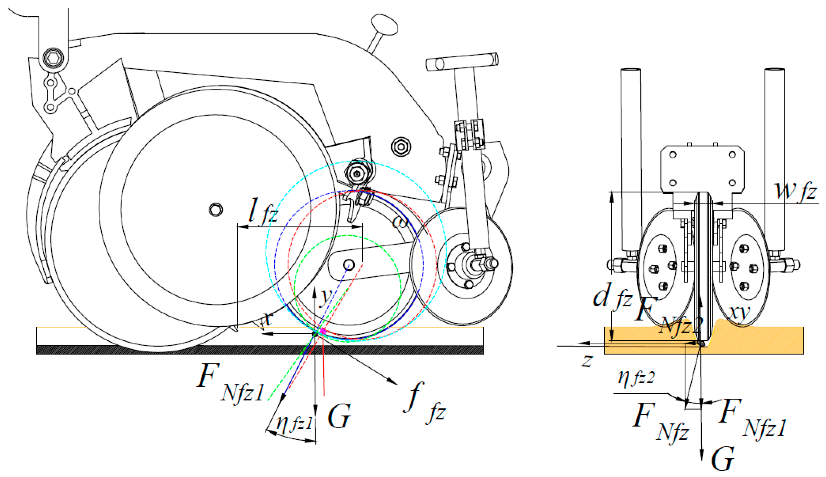
During operation, peanut seeds rapidly slide down the seeding tube. To prevent seed bounce and slippage, the seed-pressing wheel—equipped with a flexible rubber belt—makes swift, gentle contact with the seeds, applying pressure and altering their motion state. The forces exerted by the seed-pressing mechanism on peanut seeds within the seed furrow are shown in Figure 2.
An xyz three-dimensional coordinate system was established: the x-axis represents the horizontal machine-forward direction, the y-axis is vertical and perpendicular to the ground, and the z-axis aligns with the seed-pressing wheel axis, with the positive direction pointing to the left. In the xy-plane, the primary forces acting on peanut seeds include the gravitational force G, the pressure FNfz1 exerted by the seed-pressing wheel, and the frictional force resulting from relative motion between the seeds and the wheel. The friction acts tangentially along the wheel’s normal direction toward the rear of the machine’s forward direction. In the z-plane, the seeds experience a pressure component FZfz2. The seeds’ triaxial mean size, moisture content, and density are listed in Table 1.
The forces acting on the seeds are expressed as
F x = F Nfz 1 sin η fz 1 μ F Nfz 1 cos η fz 1 F y = G F Nfz 1 cos η fz 1 μ F Nfz 1 sin η fz 1 F z = F Nfz 2 F Nfz = F Nfz 1 2 + F Nfz 2 2
where Fx is the force along the x-axis (N); FNfz1 is the force in the xy-plane (N); ηfz1 is the angle (in degrees) between the tangent at the contact point of the seeds and wheel and the line connecting the tangent point to the wheel axis; μ is the friction coefficient; and G is the gravitational force (N).
The kinetic coefficient between peanut seeds and rubber ranges from 0.448 to 0.550 [26]; in this paper, μ = 0.5. As shown in Formula (1), sinηfz1 > 0, cosηfz1 > 0, μ > 0, so the value of Fy is always less than 0, indicating that the seed-pressing wheel applies pressure on the seeds in the negative y-direction.
Differentiating Fx with respect to ηfz1 yields
d F x d η fz 1 = F Nfz 1 cos η fz 1 + μ F Nfz 1 sin η fz 1 = F Nfz 1 ( cos η fz 1 + μ sin η fz 1 )
From the derivative Formula (2), it can be seen that the derivative of Fx is positive. This means that the pressure exerted by the peanut seed-pressing wheel on seeds along the positive x-axis increases as the contact angle ηfz1 increases. As shown in Figure 2, when the wheel diameter increases, the contact angle ηfz1 decreases. From Equation (1) and derivative Equation (2), it follows that when the angle is small, the pressure along the positive x-axis (forward direction) decreases, while the pressure in the negative y-direction increases.
The green and blue circles in the diagram represent different seed-pressing wheel sizes. The green wheel has a larger contact angle, resulting in reduced vertical force and increased horizontal forward force on the peanut seeds. Compared to the blue wheel, its performance is inferior. Due to limited space in front of the sowing monolithic mulch suppression device and based on experience, the seed-pressing wheel diameter (dfz) is set within the range of 150–250 mm. The red and blue circles in the diagram represent wheels positioned at different distances from the seeding-tube outlet. The red wheel has a smaller contact angle, which is more effective for pressing peanut seeds into the soil. However, it is positioned farther from the seeding tube, so seeds need more time to reach it after being ejected. Therefore, the distance between the seed-pressing wheel mounting shaft and the seeding-tube outlet is critical for effective seed pressing. Based on experimental simulations and empirical analysis, DCSPW-STO should be set between 140 mm and 160 mm. The width of the seed-pressing wheel depends on the bottom width of the seed furrow. In this paper, the wheel width wfz is set to 25 mm.
Backfilling Device
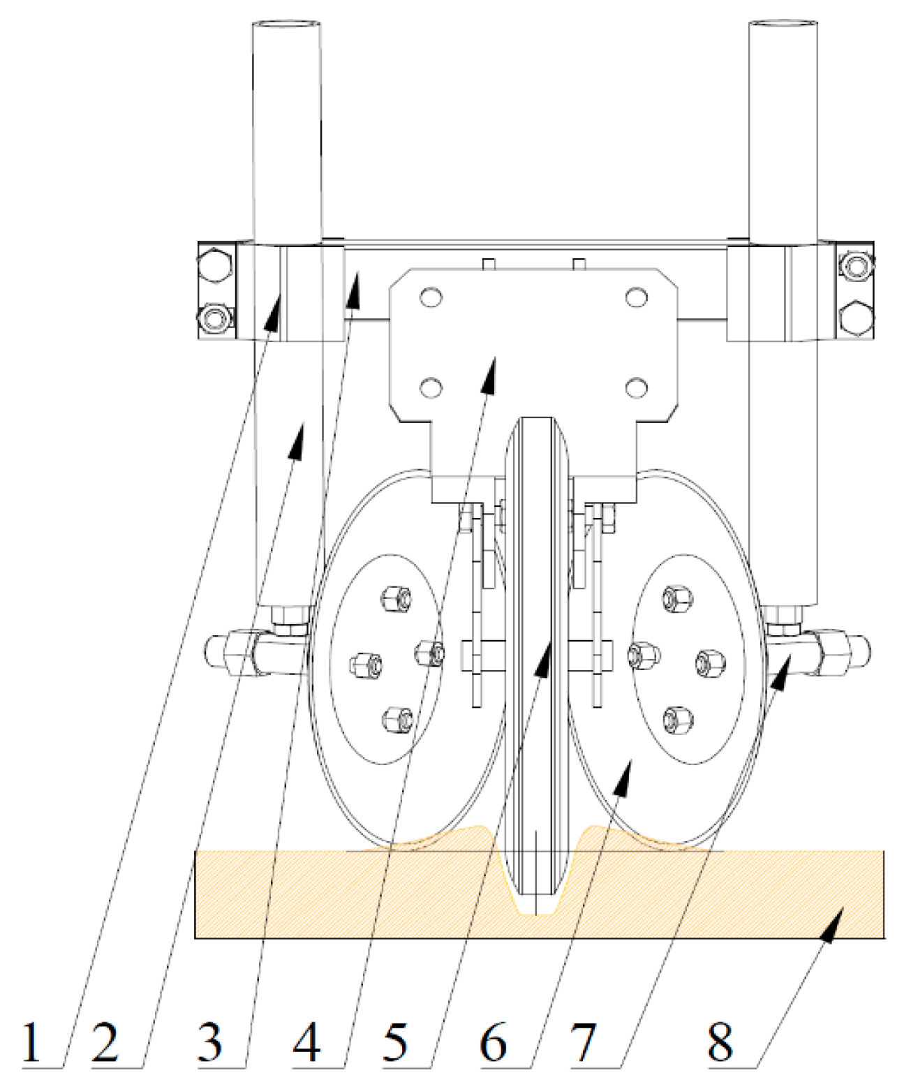
During high-speed peanut seeding, the dual-disc furrow opener creates a V-shaped seed furrow in the soil with a depth of 30 to 50 mm. Although soil on both sides of the furrow contributes to backfilling, the amount is relatively small. Therefore, the furrows must be backfilled using either a disc-type soil-covering mechanism or a cone-shaped soil-return mechanism. In this study, an adjustable disc-type soil-covering mechanism was designed, as shown in Figure 3.
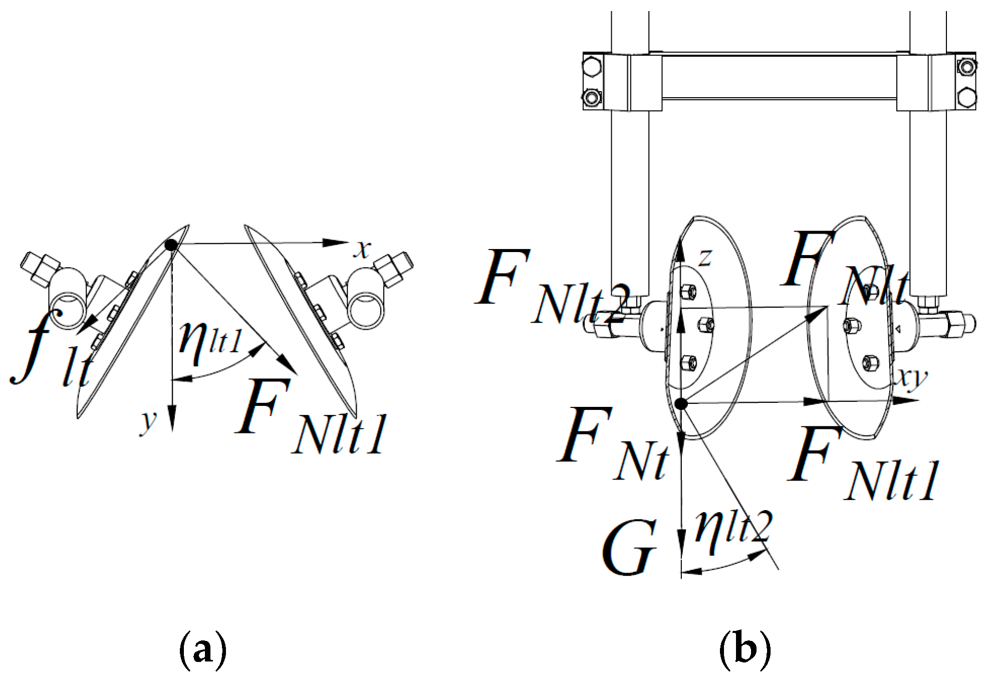
Based on the structure of the disc-type soil-covering mechanism, research was conducted to enhance the performance and stability of soil backfilling on both sides of the seed furrow during high-speed operation. The effect of the mechanism on seed-furrow soil is shown in Figure 4. Here, the x-axis is horizontal and perpendicular to the seed furrow, pointing toward the furrow; the y-axis aligns with the mechanism’s forward movement; and the z-axis is vertical, perpendicular to the ground surface, pointing upward. During operation, the soil on both sides of the seed furrow (yellow in Figure 3) is affected by the disc-type soil-covering mechanism, which applies normal pressure and tangential friction, enabling backfilling of the seed furrow.
As shown in Figure 4, the soil stress formula is expressed as
F x = F Nlt 1 sin η lt 1 f lt cos η lt 1 = F Nlt 1 sin η lt 1 μ F Nlt 1 cos η lt 1 F y = F Nlt 1 cos η lt 1 + f lt sin η lt 1 = F Nlt 1 cos η lt 1 + μ F Nlt 1 sin η lt 1 F z = F Nlt 2 = G F Nt F Nlt = F Nlt 1 2 + F Nlt 2 2
where FNlt1 is the force acting on soil in the xy-plane (N); flt is the friction force exerted on the soil by the disc-type soil-covering mechanism (N); ηlt1 is the angle between the vertical direction of the disc and the mechanism’s forward direction (°); μ is the soil–disc friction coefficient; FNlt2 is the force on the soil in the y-direction (N); FNlt is the resultant force exerted on the soil by the disc-type soil-covering mechanism (N); FNt is the resultant force exerted on the soil by surrounding soil (N); and G is the gravitational force acting on the soil (N).
From Equation (3), FNlt1 > 0, μ > 0, sinηlt1 > 0, and cosηlt1 > 0, so the value of Fy is always greater than zero. That is, the force along the machine’s forward direction is always greater than zero. According to previous research, the kinetic friction coefficient between soil and an excavator shovel is 0.05 [27]. Substituting this into Formula (3) yields the following results: when 0° < FNlt1 < 29.67°, Fy < 0; when 29.67° < FNlt1 < 90°, Fy > 0. As shown in Figure 4, a larger inclination angle requires a larger-diameter disc to maintain a constant working width. Considering operational effectiveness, overall machine length, and backfilling requirements, the single-side tilt angle ηlt3 of the circular disc ranges from 25° to 45°.
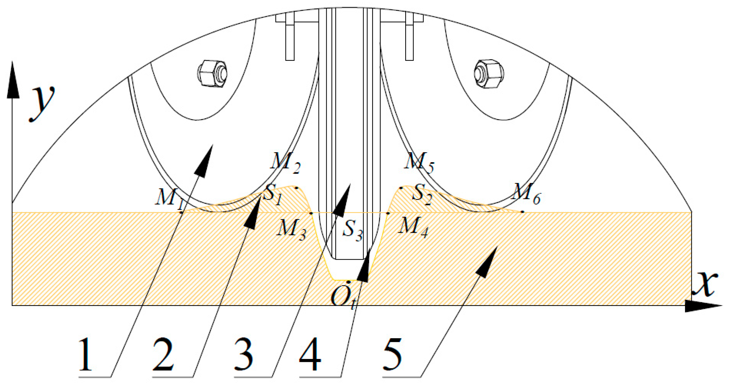
To backfill soil from both sides of the seed furrow (areas S1 and S2) into the seed furrow (area S3), as shown in Figure 5, soil compaction occurs during backfilling. To fulfill the soil-covering function, the following requirements must be met:
S 1 + S 2 S 3
where S1 is the cross-sectional area of the soil mound after double-disc furrowing, enclosed by curves M1M2, M2M3, and the horizontal line M1M3 (mm2); S2 is the cross-sectional area of the soil mound on the other side, enclosed by curves M4M5, M5M6, and the horizontal line M4M6 (mm2); S3 is the area of seed-furrow coverage area after soil-gathering and soil-covering wheel operation, enclosed by curves M3M4, M4Ot, and M3Ot (mm2).
Based on soil characteristics, when the soil area on both sides is less than the furrow’s cross-section, the disc angle must be adjusted (Figure 3). The angle adjustment device alters the disc’s entry angle into the soil, increasing the soil-covering area. When excess soil accumulates on both sides of the seed furrow, the surplus soil flows through the central gap in the disc-type soil-covering mechanism (behind the seed-pressing wheel, Figure 5), preventing soil blockage.

2.2. Simulation Model and Boundary Conditions

2.2.1. Soil-Particle Modeling

To investigate the interactions between soil and machinery, as well as between soil and seeds, a soil parameter model was established using the discrete element method. Soil consists of particles of varying diameters, ranging from large to small, with some particles spherical, and others flattened. To realistically represent soil while reducing the number of particles and improving computational efficiency, adjustments were necessary. Considering high-speed operation, the soil groove width and depth must accommodate the peanut sowing unit (width ≥ 400 mm; depth > 50 mm). Using only 6 mm diameter particles to generate the soil trough would require 660,000–700,000 particles, making the simulation inefficient. Therefore, a subset of the 6 mm diameter particles was used to enable more practical simulation testing.
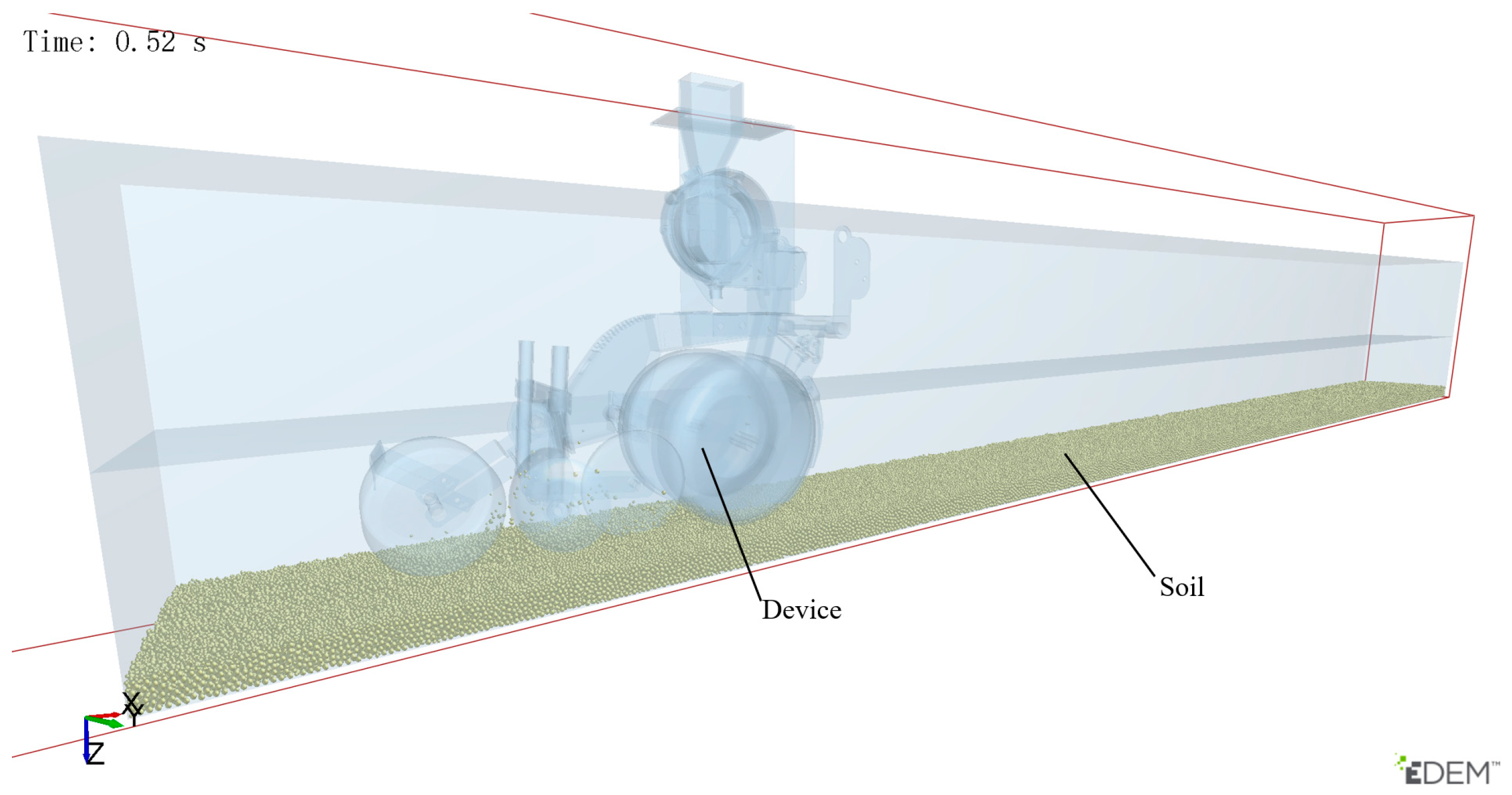
This paper established three soil particle models: the first model consists of individual spherical particles with a diameter of 6 mm; the second model consists of cylindrical particles formed by two spherical particles, each with a diameter of 6 mm and a length of 8 mm; and the third model consists of individual spherical particles with a diameter of 10 mm. The three models generated a total of 250,000 particles, distributed as follows: Type I (20%), Type II (20%), and Type III (60%). To enhance simulation speed and software efficiency, a soil channel suitable for a single-row peanut high-speed seeder was created. The earthen trough measured 6000 mm in length, 400 mm in width, and 60 mm in height, as shown in Figure 6. Soil physical parameters are listed in Table 2.

2.2.2. Seed-Particle Modeling

EDEM primarily employs the multi-sphere method and bonded-particle method to model and analyze irregularly shaped seeds. Both methods have been widely applied to rice, soybean, corn, and peanut seeds. This study uses EDEM to simulate and analyze seed displacement and the compression mulching process, including the motion of peanut seeds under different operational conditions and structural parameters [28].
Due to the large number of soil particles in the simulation, white-sand peanut seeds were modeled using the multi-sphere method during the rapid seed-casting session to simplify computation and reduce simulation time. The seeds’ physical properties, including Poisson’s ratio and shear modulus, are listed in Table 2 [25]. The constructed seed model is shown in Figure 7.

2.2.3. Geometric Modeling

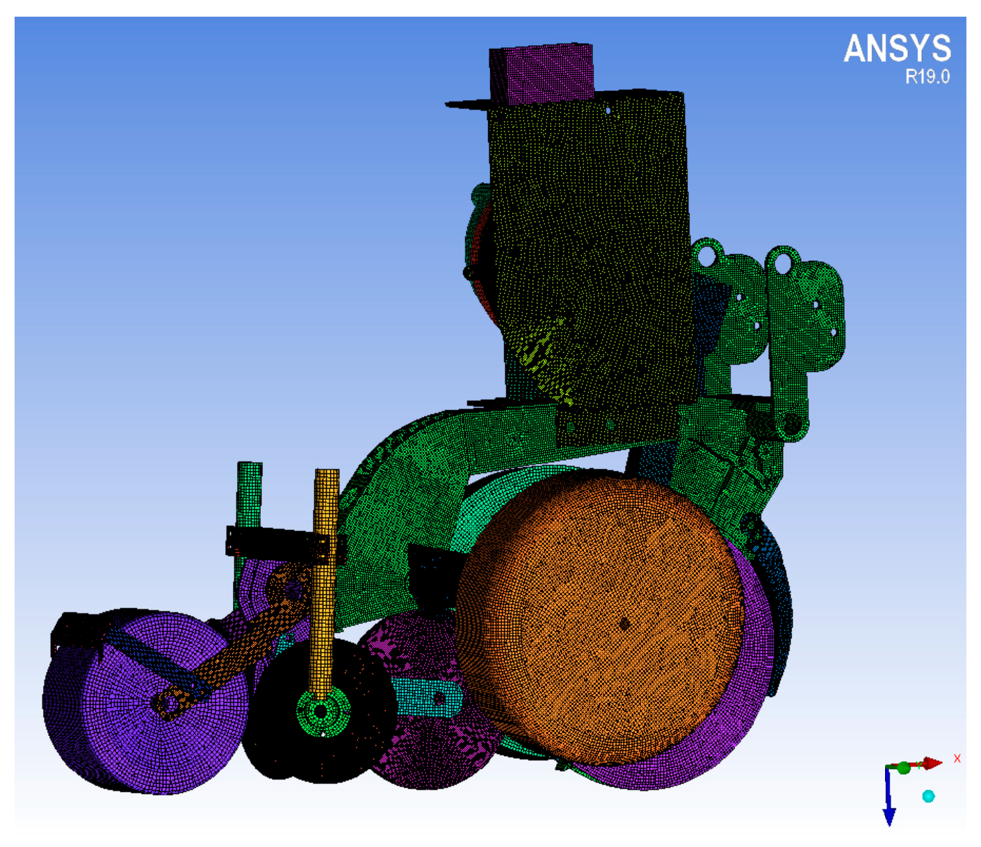
To facilitate grid partitioning and simulation, the structure of the precision seed-placement unit for peanuts was optimized. Components unrelated to seed movement—such as the motor, drive shaft, and connecting elements (bolts and nuts)—were removed. The seed-placement mechanism was simplified to include the seed distributor, frame, seeding tube, seed-pressing mechanism, soil-covering mechanism, and soil-compacting device. A simplified simulation model of the seed-pressing mechanism was created using SolidWorks 2023 and saved in STP (AP214) format. The ICEM-CFD module in ANSYS (ANSYS 2019 R1, ANSYS Inc., Canonsburg, PA, USA) was then used for surface meshing, producing 992,407 mesh elements, as shown in Figure 8. The double-disc coulters and disc-type soil-covering mechanism that contact the soil are made of steel, with material properties listed in Table 2.

2.2.4. Calculation Conditions and Parameters

In EDEM (EDEM 2018 Altair Engineering, Michigan, USA), the material properties of seed particles and dispensers must be configured, along with the contact parameters between seed particles and other particles [25], and between seed particles and dispensers [29]. The collision restitution coefficient, static friction coefficient, and dynamic friction coefficient between peanut seeds and nylon material, 65Mn, soil, rubber, and seed–seed interactions were determined through testing. The measured peanut seed particle contact parameters are shown in Table 2.
This paper focuses on the seed-pressing process. To simplify the simulation and reduce computational time, the rotation of seeds within the seed distribution tray was neglected. A seed factory was established at the seed suction port, where the seed distribution tray is blocked by the air leakage ring.
The particle factory was configured as a square generator with 12 × 12 mm cells, oriented along the axis at the seed suction hole. The number of seeds generated per second by the seed dispenser was determined by the conversion between the machine’s forward speed and the plant spacing. The basic simulation conditions were as follows: peanut plant spacing of 15 cm, seed-tray diameter of 216 mm, 35 seed suction holes, negative pressure of −6 kPa, and machine forward speeds of 6 km h−1, 8 km h−1, and 10 km h−1. The number of particles generated per second and the initial particle velocities are shown in Table 3.
Since there was no adhesion between peanut particles or between peanut particles and the seeding device, the Hertz–Mindlin model (no-slip) was selected.
The depth-limiting wheel of the high-speed precision peanut seeder contacted the soil surface, with its dual-disc furrow opener set to a seeding depth of 4 cm. The subsequent soil-covering and seed-pressing mechanisms were tangential to the soil surface. Since peanut planting often occurs after rainfall or following soil irrigation, the soil remained relatively moist, causing adhesion between soil particles, between soil and the double-disc coulters, between soil and the seed-pressing mechanism, and between soil and the packer. The soil–soil contact model was constructed using the Hertz–Mindlin with bonding model to simulate cohesive forces between soil particles. The normal stiffness per unit area was set to 2.35 × 10⁶ N m−2, the shear stiffness per unit area to 1.8 × 10⁶ N m−2, the critical normal stress to 2.3 × 10⁵ N m−2, and the critical shear stress to 1.88 × 10⁵ N m−2. The Hertz–Mindlin (no-slip) model was simultaneously used to model contacts between the soil and the seed-pressing mechanism, as well as between the soil and the compaction device. The contact parameters between soil and soil, steel and rubber are shown in Table 2 [30,31,32]. The contact parameters between peanut seeds and seeds, steel, soil, rubber and Nylon Plastic were obtained through tests and the results are shown in Table 2.
EDEM simulation was employed. To simplify the simulation, the seed-by-seed generation method was selected to construct the preliminary module for simulating the seeding operation and seed pressing. The simulation grid size in EDEM was set to 3R, the time step to 1 × 10⁻⁵ s, and the total simulation time to 5.0 s. Data were saved at 0.01 s intervals to facilitate subsequent observation of seed forces, velocities, and other motion parameters.

2.3. Experimental Program

2.3.1. Coupled Simulation Experimental Design

Based on the structural design and theoretical analysis described earlier, DCSPW-STO, the seed-pressing wheel diameter, and the machine operating velocity were identified as key factors influencing seed-movement characteristics during the seed-pressing process. To accurately determine the effects of these factors on seed-pressing performance, a three-factor, three-level experiment was conducted. DCSPW-STO, the seed-pressing wheel diameter, and the machine operating velocity were used as test factors, while the plant-spacing qualification index within seed furrows and the seeding-depth compliance index served as evaluation indicators. Design-Expert (Design-Expert 8.0.6 Stat-Ease, Minneapolis, MN, USA) was used for BBD experimental design and data processing. The test procedures, results, and evaluation criteria followed GB/T 6973-2005, “Testing Methods of Single Seed Drills (Precision Drills)” [33]. DCSPW-STO (lfz) ranged from 140 mm to 160 mm, the seed-pressing wheel diameter (dfz) ranged from 150 mm to 250 mm, and the machine operating velocity (v) ranged from 6 km h−1 to 10 km h−1. The experimental factors are shown in Table 4.

2.3.2. Experimental Design

To further investigate the effects of structural parameters—including DCSPW-STO, the seed-pressing wheel diameter, and the machine operating velocity—on peanut seed-pressing performance, an optimally designed prototype was fabricated and installed on an air-suction precision peanut seed dispenser for field testing. After the device stabilized at a constant speed, plant spacing and seeding depth within the seed furrows were observed. The seed-tray rotation speed and machine operating velocity settings are shown in Table 5.

2.3.3. Test Indicators and Measurement Methods

Testing followed GB/T 6973-2005, “Testing Methods of Single Seed Drills (Precision Drills)”. When the pneumatic precision peanut seeder operated smoothly at the specified speed, data on plant spacing and seeding depth within the seed furrows were collected. For each test, a measurement length of 5 m was selected. Each test was repeated four times, and the mean value was calculated. The plant-spacing qualification index Y1 and the seeding-depth qualification index Y2, used as test indicators, were calculated as follows:
Y = n 1 N × 100 % Y = n 2 N × 100 %
where n1 is the number of seeds meeting the required spacing, n2 is the number of seeds meeting the required sowing depth, and N is the total number of peanut seeds measured.

3. Results and Discussion

3.1. Discrete Element Simulation Results and Analysis

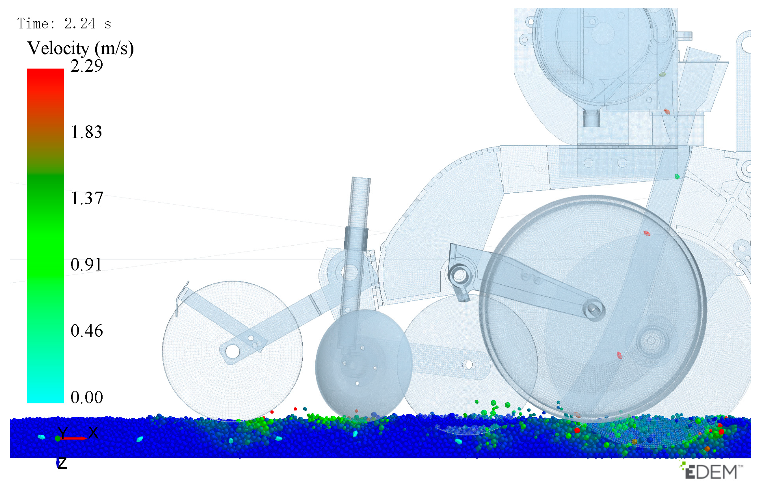
Figure 9 illustrates the effectiveness of the peanut seeder’s seed-pressing and soil-covering mechanisms at different stages of the seed-pressing operation. Figure 9a shows the initial moment when the seed-pressing and soil-covering mechanisms of the peanut seeder begin at 0.0 s. Figure 9b and Figure 9c show the seed-pressing states after the seeds were discharged from the seeding tube into the seed furrow at 2.0 s and 3.0 s, respectively.
After the simulation, the EDEM software (EDEM 2018 Altair Engineering, Michigan, USA) sampling module randomly selected soil samples from the area behind the seeder’s seed press. The extraction area was defined as the region within 50 mm of the seed furrow, with the right side of the seeder designated as a masking zone, as shown in Figure 10.
Soil particles in the masked area on the right side of Figure 10 were hidden to allow observation of seed-sowing conditions, as shown in Figure 11.
The coordinates of surface soil and seed particles within the area were extracted and imported into AutoCAD 2021 (AutoCAD 2021, Autodesk, Inc., San Rafael, CA, USA). Plant spacing and seeding depth were measured in AutoCAD 2021 (AutoCAD 2021, Autodesk, Inc., San Rafael, CA, USA), as shown in Figure 12. The distance between two seeds is denoted as li, and the seeding depth as si. The plant-spacing qualification index and the seeding-depth compliance index are defined as
M Z 30   mm l i M Z + 30   mm M S 10   mm s i M S + 10   mm
where MZ is the theoretical plant spacing and MS is the theoretical seeding depth.
Figure 12 shows a schematic of the relative positional relationship between the soil and seeds, illustrating the data collection method.
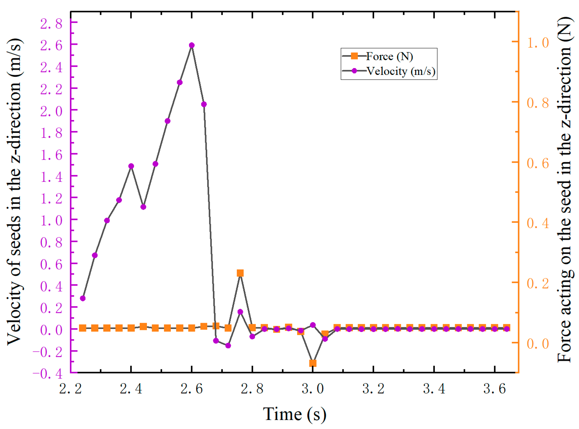
To accurately display the movement of peanut seeds during the seeding process, one simulation process was randomly selected for analysis. In this test, the distance between the center of the seed-pressing wheel and the seeding-tube outlet was set to 150 mm, the seed-pressing wheel diameter to 200 mm, and the machine operating velocity to 6 km h−1. Data were collected for a single peanut seed throughout its motion from discharge to placement in the seed furrow. At 1.4 s time interval (2.24 s to 3.64 s) was extracted to capture the vertical force and velocity of the seed, as shown in Figure 13.
As shown, the seed experiences gravitational force in the vertical direction, causing its velocity to increase. At 2.4 s and 2.6 s, the direction of velocity changes due to collisions between the peanut seeds and the seed tube. At 2.68 s, the seed’s velocity along the z-axis becomes negative, indicating upward movement. The analysis shows that when seeds come into contact with soil, a bouncing phenomenon occurs, reversing the direction of seed movement. Between 2.68 and 2.76 s, the force acting on the peanut seed changes, and its velocity also changes. During this period, the peanut seeds are subjected to the action of the seed-pressing wheel, achieving effective seed compaction. At 3.0 s, the force acting on the seed is negative, showing an upward direction. The analysis indicates that as the wheel compacts the soil, pressure is exerted on the soil within the seed furrows, generating compressive force on the seeds, causing slight movement. Subsequently, the seed experiences a constant force along the z-axis with a velocity of zero.
The qualification definitions for plant spacing and seeding depth satisfy Formula (6), which was used to calculate the plant-spacing qualification index and the seeding-depth compliance index. The test results are shown in Table 6.
Using Design-Expert (Design-Expert 8.0.6 Stat-Ease, Minneapolis, MN, USA), an analysis of variance was performed on the results of the peanut-seeding and soil-compaction experiment. The ANOVA and regression model results were extracted, with the ANOVA data shown in Table 7. The data extracted from Design-Expert (Design-Expert 8.0.6 Stat-Ease, Minneapolis, MN, USA) were used to establish a quadratic polynomial regression model describing the influence of the seed-pressing mechanism on the plant-spacing qualification index and the seeding-depth compliance index. The equations are as follows:
Y 1 = 91.47 3.13 X 1 1.91 X 2 2.82 X 3 + 1.92 X 1 X 2 + 1.88 X 1 X 3 0.53 X 2 X 3 1.76 X 1 2 2.56 X 2 2 2.45 X 3 2
Y 2 = 90.26 1.20 X 1 + 0.98 X 2 1.20 X 3 + 1.32 X 1 X 2 1.22 X 1 X 3 1.13 X 2 X 3 3.22 X 1 2 0.82 X 2 2 0.27 X 3 2
Table 7 presents the results of the regression equation analysis for both indices. As shown, the p-values for both the peanut plant-spacing qualification index model and the peanut seeding-depth compliance index model are highly significant (p < 0.01). Additionally, the p-values for the residual terms of both models exceed 0.05, indicating that the experimental design is reasonable and feasible. These results also confirm that both models fit the experimental data well, making them suitable for further testing and analysis.
Table 7 shows that, based on the plant-spacing qualification index, the p-values for DCSPW-STO (X1), the seed-pressing wheel diameter (X2), the machine operating velocity (X3), and the interaction terms X1X2, X1X3, X 1 2 , X 2 2 , and X 3 2 are all less than 0.01, indicating a highly significant influence on the plant-spacing qualification index after peanut planting. In contrast, the p-value for the interaction term X2X3 is greater than 0.05, indicating that this factor does not significantly affect the plant-spacing qualification index after seed pressing. The seeding-depth compliance index indicates that the p-values for DCSPW-STO (X1), the seed-pressing wheel diameter (X2), the machine operating velocity (X3), and the interaction terms X1X2 and X1X3 are all less than 0.05, demonstrating that these factors significantly influence the seeding-depth compliance index after seeding. The p-value for the interaction term X12 is less than 0.01, indicating a highly significant effect on the seeding-depth compliance index after seed pressing. The p-values for the interaction terms X2X3, X 2 2 , and X 3 2 are all greater than 0.05, indicating that these factors do not significantly influence the seeding-depth compliance index after rolling.
To ensure the significance of the regression equation model, non-significant terms were removed. The regression equations for the plant-spacing qualification index and the seeding-depth compliance index are
Y 1 = 91.47 3.13 X 1 1.91 X 2 2.82 X 3 + 1.92 X 1 X 2 + 1.88 X 1 X 3 1.76 X 1 2 2.56 X 2 2 2.45 X 3 2
Y 2 = 90.26 1.20 X 1 + 0.98 X 2 1.20 X 3 + 1.32 X 1 X 2 1.22 X 1 X 3 3.22 X 1 2
The regression model indicates that the primary and secondary factors influencing the plant-spacing qualification index after peanut planting are DCSPW-STO (lfz), the seed-pressing wheel diameter (dfz), and the machine operating velocity (v). The main factors affecting the seeding-depth compliance index after seedbed preparation are DCSPW-STO (lfz), the machine operating velocity (v), and the seed-pressing wheel diameter (dfz).
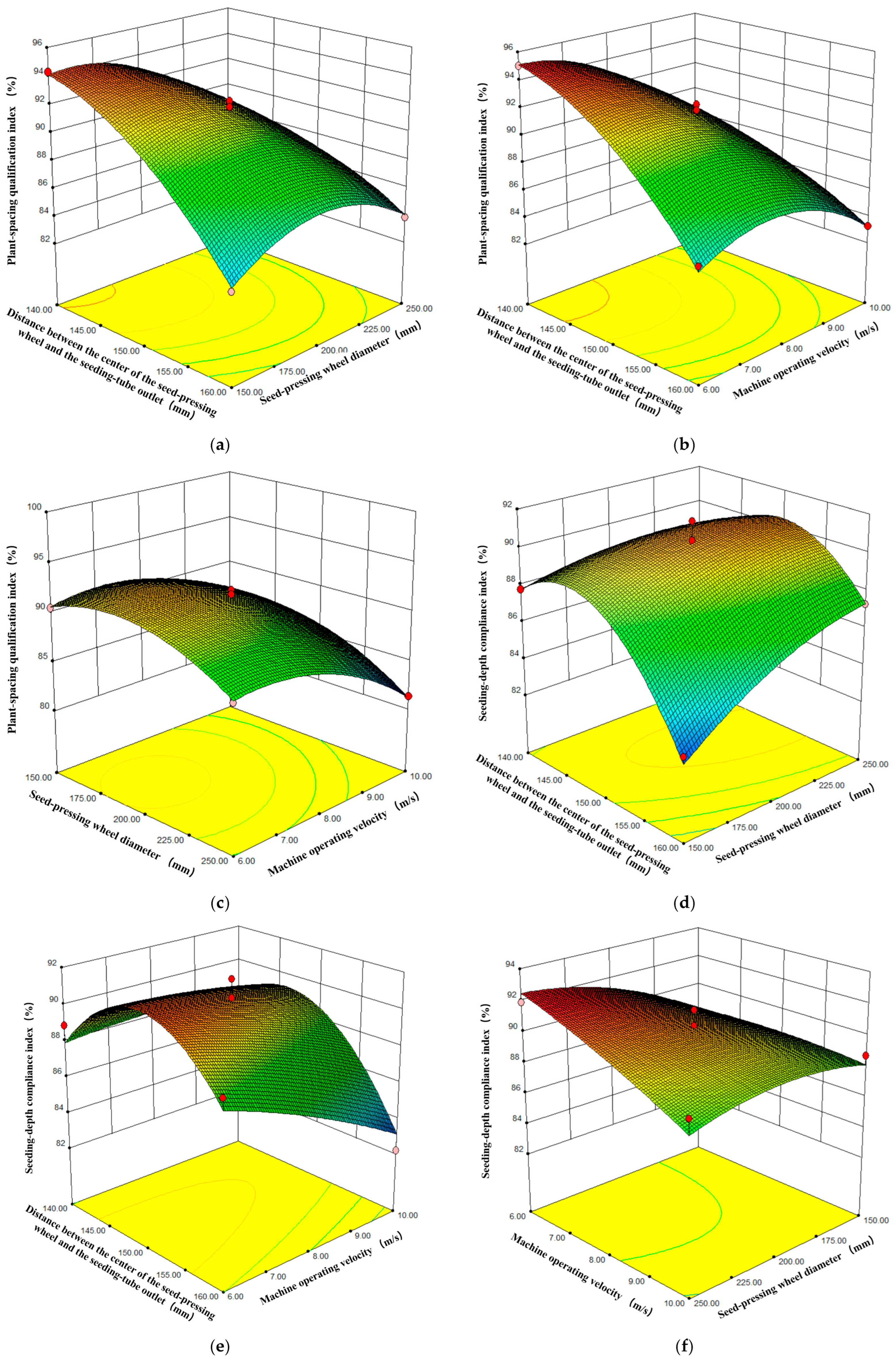
The interactions among DCSPW-STO, the seed-pressing wheel diameter, and the machine operating velocity significantly affect both the plant-spacing qualification index and the seeding-depth compliance index after seed pressing. Response surface diagrams illustrating these interactions are shown in Figure 14.
Figure 14a shows the response surface illustrating the interaction effects between DCSPW-STO and the seed-pressing wheel diameter on the plant-spacing qualification index after seed pressing at a machine operating velocity of 8 km h−1. As shown Figure 14a, the plant-spacing qualification index gradually decreases with increasing DCSPW-STO and shows a decreasing trend with increasing seed-pressing wheel diameter. The optimal range occurs when DCSPW-STO is 140–147 mm and the seed-pressing wheel diameter is 150–200 mm.
Figure 14b shows the response surface illustrating the interaction effects between the seed-pressing wheel diameter (200 mm), DCSPW-STO, and machine operating velocity on the plant-spacing qualification index after seed pressing. Under these conditions, the index decreases as DCSPW-STO and the machine operating velocity increase. Optimal values are achieved when DCSPW-STO is 140–150 mm and the machine operating velocity is 4–5 km h−1.
Figure 14c shows the response surface illustrating the interaction effects among DCSPW-STO, the seed-pressing wheel diameter, and machine operating velocity on the plant-spacing qualification index when the distance between the center of the seed-pressing wheel and the seeding-tube outlet is 150 mm. The index first increases and then decreases as the seed-pressing wheel diameter increases. With higher machine operating velocity, the index slightly increases and then rapidly declines. Optimal results are achieved when the seed-pressing wheel diameter is 175–200 mm and the machine operating velocity is 4–5.5 km h−1.
Figure 14d shows the response surface illustrating the interaction effects between DCSPW-STO and the seed-pressing wheel diameter on the seeding-depth compliance index after seed pressing, at a machine operating velocity of 8 km h−1. As shown, as DCSPW-STO increases, the index first increases and then gradually decreases. As the seed-pressing wheel diameter increases, the index shows an upward trend. Favorable results are achieved when DCSPW-STO is 144–150 mm and the seed-pressing wheel diameter is 175–225 mm.
Figure 14e shows the response surface illustrating the interaction effects between the seed-pressing wheel diameter (200 mm), DCSPW-STO, and machine operating velocity on the seeding-depth compliance index after seed pressing. Under these conditions, the index first increases and then decreases with increasing DCSPW-STO, while increasing machine operating velocity causes a downward trend. Optimal performance is achieved when DCSPW-STO is 145–155 mm and the machine operating velocity is 4–5.5 km h−1.
Figure 14f shows the response surface illustrating the interaction effects between the seed-pressing wheel diameter and machine operating velocity on the seeding-depth compliance index when DCSPW-STO is 150 mm. As shown Figure 14f, the index is not significantly affected by either parameter.
To determine the optimal structural and operational parameters for the seed-pressing mechanism of precision peanut seeders, it is necessary to optimize the rational matching between DCSPW-STO, the seed-pressing wheel diameter, and the machine operating velocity. The optimization objective is to maximize the plant-spacing qualification index and the seeding-depth compliance index, under the conditions that seed spacing is 10 cm < X ≤ 20 cm, the plant-spacing qualification index ≥ 75%, and the seeding-depth compliance index ≥ 80%. Based on the boundary conditions of the selected experimental factors, the objective function and constraints are defined as follows:
Y 1 max = X 1 , X 2 , X 3 Y 2 max = X 1 , X 2 , X 3
s . t . Y 1 max 75 % Y 2 max 80 % 140   mm X 1 160   mm 150   mm X 2 250   mm 6   km · h 1 X 3 10   km · h 1
Using the optimization module in Design-Expert (Design-Expert 8.0.6 Stat-Ease, Minneapolis, MN, USA), the optimal parameters were obtained as follows: DCSPW-STO (lfz) = 146.11 mm, the seed-pressing wheel diameter (dfz) = 198.13 mm, and the machine operating velocity (v) = 6.45 km h−1. Under these conditions, the plant-spacing qualification index and the seeding-depth compliance index reached 93.78% and 90.65%, respectively, indicating favorable planting results.

3.2. Validation Experiment

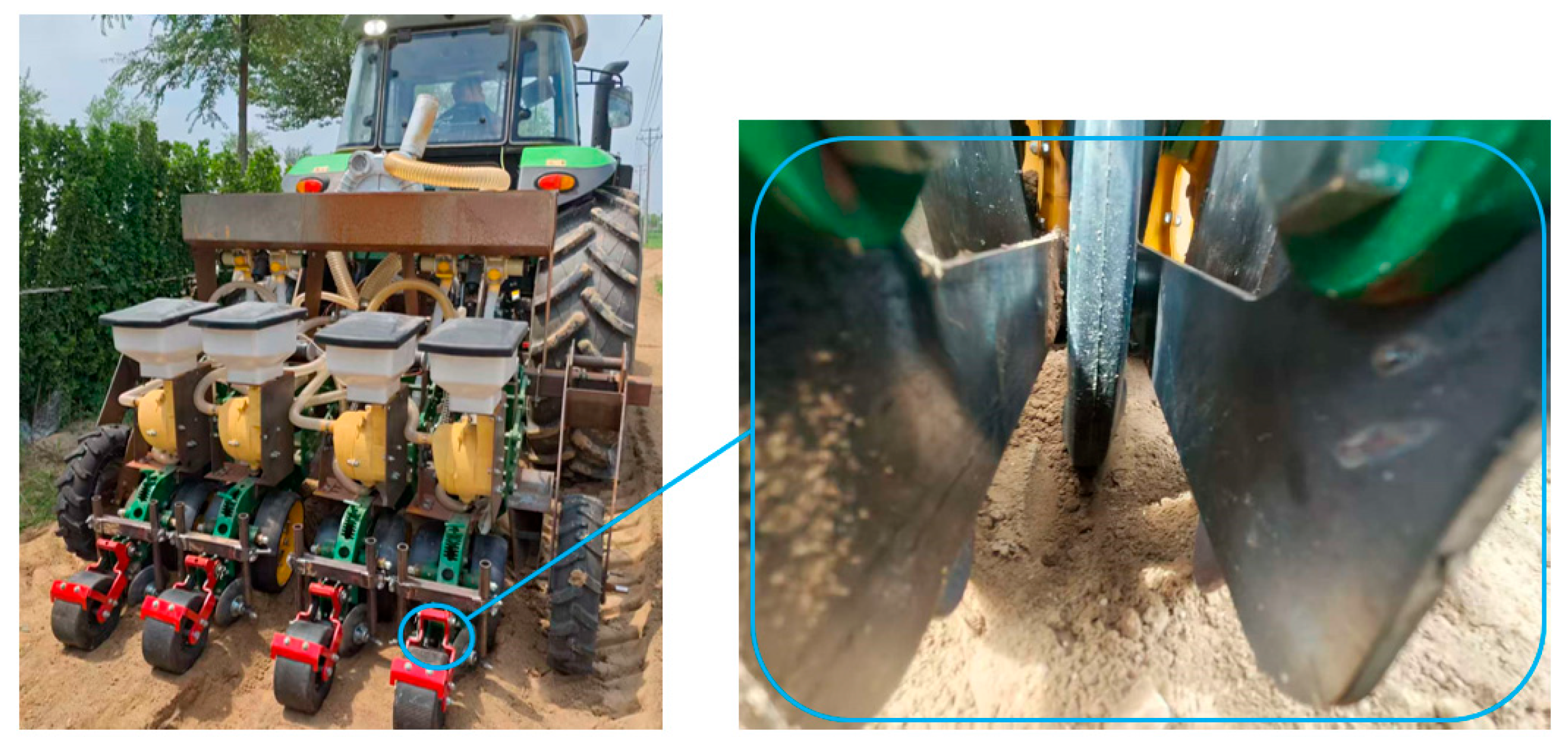
During validation of the structural design and optimal operational parameters of the seed-pressing mechanism for the precision peanut seeder under field operations, the fabrication of seed-pressing wheels with decimal-point dimensions posed significant challenges. Therefore, the diameter of the seed-pressing wheel dfz was set to 198 mm. Additionally, the installation position parameters must be restricted to integer values, so DCSPW-STO (lfz) was set to 146 mm. Under these conditions, when the machine operating velocity (v) was set to 6.45 km h−1, plant spacing and seeding depth were observed after seedbed preparation. Field trials were conducted as shown in Figure 15. White-sand peanuts were selected as the test material. The test parameters were as follows: the target plant spacing was 150 mm, and the adsorption negative pressure was set to −6.0 kPa.
After the peanut seeder reached a stable forward speed, measurements of plant spacing and seeding depth were recorded. Formula (6) was used to determine whether the measured values met the specified requirements, and Formula (5) was applied to calculate the plant-spacing qualification index and the seeding-depth compliance index after seed pressing. Each test was repeated three times, and the mean value was taken as the final result. The test data are presented in Table 8.
As shown in Table 8, both the plant-spacing qualification index and the seeding-depth compliance index after peanut seed pressing met the requirements for peanut-seeding operations. It is evident that the seed-pressing mechanism significantly outperformed the configuration without it. Furthermore, comparison of actual operational data with multi-factor trial results shows that, although the field-trial indices were slightly lower, the difference was minimal, and the values remained closely aligned. These results demonstrate that the optimized seed-pressing mechanism holds significant reference value for precision peanut seeding and confirm that the regression model from the preliminary experiments is correct, reasonable, and feasible.

4. Conclusions

This study designed a seed-pressing mechanism and investigated the influence of its structural and operational parameters on seed-sowing performance in precision peanut seeders under saline–alkali soil conditions. By optimizing key structural parameters of the seed-pressing mechanism, timely and gentle seed compaction is ensured after seeds enter the seed furrow. This enhances seeding stability and significantly improves seeding performance during high-speed planting of large-seeded crops. The main findings are as follows:
(1)
Theoretical analysis of the seed-pressing and soil-covering mechanisms identified the key structural parameters of both components. Three primary factors influencing the plant-spacing qualification and seeding-depth compliance indices were determined: DCSPW-STO, the seed-pressing wheel diameter, and the machine operating velocity.
(2)
Experimental analysis using the discrete element method with three factors and three levels revealed the effects of the DCSPW-STO, the seed-pressing wheel diameter, and the operational velocity on peanut-seeding performance. An optimization model was then established to determine the best parameter combination: the optimal DCSPW-STO was 146.13 mm, the optimal seed-pressing wheel diameter was 198.13 mm, and the optimal machine operating velocity was 6.45 km h−1. With these settings, the seeding effect was favorable.
(3)
Field trials validated the optimized results, demonstrating that the improved seed-pressing mechanism and operational parameters meet agronomic requirements for precision peanut seeding.

Author Contributions

Conceptualization, P.G., J.H. and D.W.; methodology, P.G.; software, P.G. and F.E.; validation, P.G.; formal analysis, P.G.; investigation, P.G., Y.D. and J.Z.; resources, P.G. and D.W.; data curation, P.G. and X.Z.; writing—original draft preparation, P.G.; writing—review and editing, P.G., J.H., D.W. and S.S.; visualization, P.G. and F.E.; supervision, P.G. and H.Y.; project administration, J.H., D.W. and S.S.; funding acquisition, D.W. and J.H. All authors have read and agreed to the published version of the manuscript.

Funding

This research was funded by the Shandong Province Base and Talent Program (“Hundred Foreign Experts Program” Talent Category) Project (No. WSR2024092); the Yantai Science and Technology Program (No. 2023ZDCX029); the Shandong Province Agricultural Machinery R&D, Manufacturing and Promotion Application Integration Pilot Project (Nos. NJYTHSD-202314 and NJYTHSD-202304); the National Key Research and Development Program (No. 2022YFD2300101); and the Shandong Province Key R&D Program—Major Science and Technology Innovation Project (No. 2021CXGC010813) and the Science and Technology Demonstration Project (No. 2022SFGC0203).

Institutional Review Board Statement

Not applicable.

Data Availability Statement

The original contributions presented in this study are included in the article. Further inquiries can be directed to the corresponding authors.

Conflicts of Interest

The authors declare no conflicts of interest.

References

  1. Zhao, X.S.; Ran, W.J.; Hao, J.J.; Bai, W.J.; Yang, X.L. Design and experiment of the double-seed hole seeding precision seed metering device for peanuts. Int. J. Agri. Biol. Eng. 2022, 15, 107–114. [Google Scholar] [CrossRef]
  2. Wang, S.Y.; Hu, Z.C.; Chen, Y.Q.; Wu, H.C.; Wang, Y.W.; Wu, F.; Gu, F.W. Integration of agricultural machinery and agronomy for mechanised peanut production using the vine for animal feed. Biosyst Eng. 2022, 219, 135–152. [Google Scholar] [CrossRef]
  3. He, S.N.; Chen, Y.; Xiang, W.; Chen, X.W.; Wang, X.L.; Chen, Y. Carbon and nitrogen footprints accounting of peanut and peanut oil production in China. J. Clean. Prod. 2021, 291, 125964. [Google Scholar] [CrossRef]
  4. Guo, P.; Zheng, X.S.; Wang, D.W.; Hou, J.L.; Zhao, Z. Design and Experiment of Precision Seed Metering Device with Pneumatic Assisted Seed-filling for Peanut. Trans. Chin. Soc. Agric. Mach. 2024, 55, 64–74. [Google Scholar]
  5. Yin, X.W.; Yang, L.; Zhang, D.X.; Cui, T.; Han, D.D.; Zhang, T.L.; Yu, Y.M. Design and experiment of balance and low-loss air allotter in air pressure maize precision planter. Trans. Chin. Soc. Agri. Eng. 2016, 32, 9–17. [Google Scholar] [CrossRef]
  6. Wang, Y.B.; Li, H.W.; Hu, H.N.; He, J.; Wang, Q.J.; Lu, C.Y.; Liu, P.; He, D.; Lin, X. DEM–CFD coupling simulation and optimization of a self-suction wheat shooting device. Powder Technol. 2021, 393, 494–509. [Google Scholar] [CrossRef]
  7. Wang, D.W.; Ji, R.Q.; He, X.N.; Guo, P.; Shi, Y.X.; Zhang, C.X. Drive-guided Combination Slot-assisted Seed-attached Air-absorbing Peanut High-speed Precision Seed Meter. Trans. Chin. Soc. Agri. Mach. 2023, 54, 59–70+149. [Google Scholar] [CrossRef]
  8. Li, Y.H.; Yang, L.; Zhang, D.X.; Cui, T.; Ding, L.; Wei, Y.N. Design and Experiment of Pneumatic Precision Seed-metering Device with Single Seed-metering Plate for Double-row. Trans. Chin. Soc. Agric. Mach. 2019, 50, 61–73. [Google Scholar] [CrossRef]
  9. Xing, H.; Cao, X.M.; Zhong, P.; Wan, Y.K.; Lin, J.J.; Zang, Y.; Zhang, G.Z. DEM-CFD coupling simulation and optimisation of rice seed particles seeding a hill in double cavity pneumatic seed metering device. Comput. Electr. Agri. 2024, 224, 109075. [Google Scholar] [CrossRef]
  10. Fang, Z.H.; Zhang, J.; Chen, J.C.; Pan, F.; Wang, B.W.; Ji, C. Design and Experimental Analysis of an Air-Suction Wheat Precision Hill-Seed Metering Device. Agriculture 2024, 14, 1931. [Google Scholar] [CrossRef]
  11. Liu, R.; Liu, Z.J.; Liu, L.J.; Li, Y.H. Design and Experiment of Corn High Speed Air Suction Seed Metering Device with Disturbance Assisted Seed-filling. Trans. Chin. Soc. Agri. Mach. 2022, 53, 50–59. [Google Scholar] [CrossRef]
  12. Zang, Y.; Huang, Z.S.; Qin, W.; He, S.Y.; Qian, C.; Jiang, Y.C.; Tao, W.Y.; Zhang, M.L.; Wang, Z.M. Design of hybrid rice air-suction single seed metering device. Trans. Chin. Soc. Agri. Eng. 2024, 40, 181–191. [Google Scholar] [CrossRef]
  13. Ding, L.; Yuan, Y.C.; Dou, Y.F.; Li, C.X.; He, Z.; Guo, G.M.; Zhang, Y.; Chen, B.J.; Li, H. Design and Experiment of Air-Suction Maize Seed-Metering Device with Auxiliary Guide. Agriculture 2024, 14, 169. [Google Scholar] [CrossRef]
  14. Liu, J.X.; Wang, Q.J.; Li, H.W.; He, J.; Lu, C.Y. Design and seed suction performance of pinhole-tube wheat precision seeding device. Trans. Chin. Soc. Agric. Eng. 2019, 35, 10–18. [Google Scholar] [CrossRef]
  15. Jiang, Y.Z.; Hou, X.X.; Zhao, Y.M.; Hu, B.; Luo, X.; Chen, Y.; Zhang, H. Design and experiment of air suction drum precision metering device for air blowing and seeding. J. Gansu Agric. Univ. 2022, 38, 31–41. [Google Scholar] [CrossRef]
  16. Huang, X.M.; Zhang, S.; Zhu, Y.Z.; Liu, Y. Seeding process analysis and test of the air conveying rapeseed aerial seeding device. Trans. Chin. Soc. Agric. Eng. 2022, 38, 31–41. [Google Scholar] [CrossRef]
  17. Wang, L.B.; Yang, H.Y.; Wang, Q.J.; Lu, C.Y.; Wang, C.; He, J. Design and Experiment of Air-assisted Linear Seeding Device for Wheat. Trans. Chin. Soc. Agric. Mach. 2024, 55, 111–120. [Google Scholar]
  18. Lü, J.Q.; Yang, Y.; Shang, Q.Q.; Li, Z.H.; Li, J.C.; Liu, Z.Y.; Wang, Y.B. Performance optimization test on air-suction potato seed metering device with positive pressure airflow and zero-speed seeding. Trans. Chin. Soc. Agric. Eng. 2016, 32, 40–48. [Google Scholar] [CrossRef]
  19. Siemens, M.C.; Gayler, R.R. Improving Seed Spacing Uniformity of Precision Vegetable Planters. Appl. Eng. Agric. 2016, 32, 579–587. [Google Scholar] [CrossRef]
  20. Wang, C.; Li, H.W.; He, J.; Wang, Q.J.; Lu, C.Y.; Wang, J.X. Design and Experiment of Pneumatic Wheat Precision Seed Casting Device in Rice-wheat Rotation Areas. Trans. Chin. Soc. Agric. Mach. 2020, 51, 43–53. [Google Scholar] [CrossRef]
  21. Lu, Q.; Zhao, J.H.; Liu, L.J.; Liu, Z.J.; Wang, C.L. Design and Experiment of a Soil-Covering and -Pressing Device for Planters. Agriculture 2024, 14, 1040. [Google Scholar] [CrossRef]
  22. Wang, Y.X.; Zhang, W.Y.; Yan, W.; Qi, B. Design and Experiment of Seed Pressing Device for Precision Seeder Based on Air Flow Assisted Seed Delivery. Trans. Chin. Soc. Agric. Mach. 2020, 51, 69–76. [Google Scholar] [CrossRef]
  23. Ma, F.Y.; Wang, L.B.; Wang, C.; Wang, Q.J.; Lu, C.Y. Study on Impact Soil Movement Experiments on Wheat Seeds Based on EDEM. Agriculture 2025, 15, 400. [Google Scholar] [CrossRef]
  24. Zhang, T.; Tang, X.L.; Dai, C.; Ren, G.Y. Operating parameter optimization and experiment of spiral outer grooved wheel seed metering device based on discrete element method. Sci. Rep. 2025, 15, 30762. [Google Scholar] [CrossRef]
  25. Guo, P.; Sun, B.; Shang, S.Q.; Hou, J.L.; Wang, D.W.; Zhao, Z.; Elshafie, A.; Zheng, X.S.; Eltoum, F. Effect of Auxiliary Air-Suction Seed-Filling Structure on Seed Discharge Performance of Peanut High-Speed Seed-Metering Machine. Agriculture 2025, 15, 1678. [Google Scholar] [CrossRef]
  26. Chen, Y.G.; Wu, N.; Lin, D.Z.; Yu, Z.Y.; You, Z.Y.; Hu, Z.C. Study on Recovery Coefficient and Friction Coefficient of Peanut Kernels. Jiangsu Agric. Sci. 2016, 44, 386–390. [Google Scholar] [CrossRef]
  27. Zhao, S.H.; Gu, Z.Y.; Yuan, Y.W.; Lü, J.Q. Bionic Design and Experiment of Potato Curved Surface Sowing Furrow Opener. Trans. Chin. Soc. Agric. Mach. 2021, 52, 32–42+64. [Google Scholar] [CrossRef]
  28. Zhang, H.; Pan, F.; Han, D.L.; Liu, J.B.; Ji, C. Design and Test of a Crawler-Type On-Film Precision Cotton Seeding. Agriculture 2024, 14, 962. [Google Scholar] [CrossRef]
  29. Wu, M.C.; Cong, J.L.; Yan, Q.; Zhu, D.; Peng, X.Y.; Wang, Y.S. Calibration and experiments for discrete element simulation parameters of peanut seed particles. Trans. Chin. Soc. Agri. Eng. 2020, 36, 30–38. [Google Scholar] [CrossRef]
  30. Wei, S.; Zhang, C.H.; Zhan, Z.Y.; Nong, F.; Ding, Y.C. Simulation and Optimization Test of Imitation Furrowing Process of Cotton Direct Seeding MachineBased on DEM-MBD Coupling. Trans. Chin. Soc. Agric. Mach. 2025, 56, 275–289+341. [Google Scholar] [CrossRef]
  31. Xia, J.F.; Zhang, P.; Yuan, H.W.; Du, J.; Zheng, K.; Li, Y.F. Calibration and Verification of Flexible Rice Straw Model by Discrete Element Method. Trans. Chin. Soc. Agric. Mach. 2024, 55, 174–184. [Google Scholar] [CrossRef]
  32. Ma, S.; Xu, L.M.; Yuan, Q.C.; Niu, C.; Zeng, J.; Chen, C.; Wang, S.S.; Yuan, X.T. Calibration of discrete element simulation parameters of grapevine antifreezing soil and its interaction with soil-cleaning components. Trans. Chin. Soc. Agri. Eng. 2020, 36, 30–38. [Google Scholar] [CrossRef]
  33. GB/T 6973-2005; Testing Methods of Single Seed Drills (Precision Drills). China Standards Press: Beijing, China, 2005.
Figure 1. Schematic diagram of the seed-pressing and soil-covering mechanisms. (a) Seed-pressing and soil-covering mechanisms: (1) double-disc furrow opener; (2) frame; (3) seeding tube; (4) depth-control wheel; (5) seed-pressing mechanism; (6) soil-covering mechanism; (7) packer roller. (b) Seed-movement trajectory: the red line indicates the seed trajectory, and the yellow arrows indicate the seeds.
Agriculture 15 02246 g001
Figure 2. Force analysis of seeds in the seed furrow during operation of the seed-pressing mechanism. Blue, purple, and green lines represent seed-pressing wheels of different sizes. Red and purple lines represent seed-pressing wheels of the same size, but they are installed in different positions.
Agriculture 15 02246 g002
Figure 3. Schematic diagram of the soil-covering mechanism. (1) Disc mounting clamp; (2) disc mounting pipe; (3) disc mounting crossbar; (4) disc mounting frame; (5) seed-pressing wheel; (6) soil-covering disc; (7) disc rotation shaft; (8) soil.
Agriculture 15 02246 g003
Figure 4. Schematic diagram of soil stress analysis on both sides of the seed furrow. (a) Top view; (b) Front view.
Agriculture 15 02246 g004
Figure 5. Schematic diagram of soil profile on both sides of the seed furrow and seed furrow shape. (1) disc-type soil-covering mechanism; (2) soil on both sides of the seed furrow; (3) seed-pressing wheel; (4) seed furrow; (5) soil.
Agriculture 15 02246 g005
Figure 6. Schematic diagram of a single-cell ridge-shaped soil trough.
Agriculture 15 02246 g006
Figure 7. Peanut seed: actual photo and model diagram.
Agriculture 15 02246 g007
Figure 8. Schematic diagram of the individual grid for the precision peanut-seeding device.
Agriculture 15 02246 g008
Figure 9. Effects of seed-pressing and soil-covering mechanisms on peanut seedlings at different stages. (a) 0.0 s, (b) 2.0 s, (c) 3.0 s.
Agriculture 15 02246 g009
Figure 10. Extraction zone within 50 mm of the seed furrow. Blue, green, and red represent soil at different speeds; brown represents peanut seeds. The red box indicates the extraction area, while the white box denotes the later concealment zone.
Agriculture 15 02246 g010
Figure 11. Seed-sowing conditions after concealing soil particles on the right side.
Agriculture 15 02246 g011
Figure 12. Seed-sowing conditions after concealing soil particles on the right side. Yellow represents single-layer soil; blue represents seeds.
Agriculture 15 02246 g012
Figure 13. Force acting on a seed in the vertical direction and its velocity during the time interval 2.24–3.64 s.
Agriculture 15 02246 g013
Figure 14. Response surface diagrams illustrating the effects of planting interactions on the plant-spacing qualification index and the seeding-depth compliance index after peanut seedbed preparation. (a) The influence of the interactive term DCSPW-STO and seed-pressing wheel diameter on the plant-spacing qualification index; (b) The influence of the interactive term DCSPW-STO and machine operating velocity on the plant-spacing qualification index; (c) The influence of the interactive term seed-pressing wheel diameter and machine operating velocity on the plant-spacing qualification index; (d) The influence of the interactive term DCSPW-STO and seed-pressing wheel diameter on the seeding-depth compliance index; (e) The influence of the interactive term DCSPW-STO and machine operating velocity on the seeding-depth compliance index; (f) The influence of the interactive term seed-pressing wheel diameter and machine operating velocity on the seeding-depth compliance index.
Agriculture 15 02246 g014
Figure 15. Field experiment.
Agriculture 15 02246 g015
Table 1. Physical properties of peanut seeds.
Physical PropertyParameter
Average size of three axes (mm)15 × 10 × 8.5
Density (kg·m−3)1049
Moisture content (%)8.87
Table 2. Contact parameters of peanut seed particles with materials.
MaterialsParametersPeanutsSteelSoilRubberNylon Plastic
Poisson’s ratio0.3620.310.410.460.38
Shear modulus (Pa)5.06 × 1077.85 × 10101.31 × 1060.6 × 1063.11 × 109
Density (kg m−3)10407850232012001130
Seeds and MaterialsRestitution coefficient0.5010.630.340.180.519
Static friction coefficient0.2130.330.240.310.441
Rolling friction coefficient0.0350.260.070.250.126
Soil and MaterialsRestitution coefficient0.340.350.350.61/
Static friction coefficient0.240.600.350.48/
Rolling friction coefficient0.070.100.260.23/
Time step (s)1 × 10⁻⁵
Table 3. Relationship between the particle generation rate and the initial velocity of particles relative to the forward speed of the machinery.
Forward Speed of the Machine
(km h−1)
Particle Factory Production Rate per SecondInitial Velocity of Generated Particles
(m s−1)
6110.2
8150.266
10190.333
Table 4. Test factors and levels.
Level CodeExperimental Factors
Distance Between the Center of the Seed-Pressing Wheel and the Seeding-Tube Outlet
(mm)
Seed-Pressing Wheel Diameter
(mm)
Machine Operating Velocity
(km h−1)
−11401506
01502008
116025010
Table 5. Seed-tray rotation speed and machine operating velocity settings.
NumberMachine Operating Velocity
(km h−1)
Seed-Tray Rotation Speed
(rpm)
1619.09
2825.38
31031.79
Table 6. Experimental design and results.
Experimental FactorsPlant-Spacing Qualification IndexSeeding-Depth Compliance Index
X1X2X3Y1%Y2%
10−1−190.5387.3
200091.2491.5
3−1−1094.3187.8
400090.6390.3
50−1186.2688.7
6−10−195.0288.9
711083.8487.3
8−11086.6986.7
901−187.7291.9
1000091.8490.5
1110183.2682.2
1210−185.4488.6
131−1083.7783.1
1401181.3388.8
1500092.2589.6
1600091.3989.9
17−10185.3287.4
Table 7. Analysis of variance data.
SourcePlant-Spacing Qualification IndexSeeding-Depth Compliance Index
Sum of SquaresDegrees of FreedomFpSum of SquaresDegrees of FreedomFp
Model274.46369102.4545<0.0001 **99.51682910.345090.0028 **
X178.312611263.0999<0.0001 **11.52110.777870.0134 *
X229.22301198.17793<0.0001 **7.60517.1150760.0321 *
X363.506451213.3569<0.0001 **11.52110.777870.0134 *
X1X214.78403149.668560.0002 **7.022516.5701020.0374 *
X1X314.1376147.496830.0002 **6.002515.6158110.0496 *
X2X31.123613.7748580.09315.062514.7363670.0660
X 1 2 13.02401143.755590.0003 **44.95392142.057930.0003 **
X 2 2 27.56716192.61493<0.0001 **3.16865812.9645290.1288
X 3 2 25.29948184.99639<0.0001 **0.42444710.3971040.5486
Residual2.0835757 7.4827
Lack of fit0.57337530.5062240.69875.3733.3901520.1345
Errors1.51024 2.1124
Total276.547216 106.998816
* indicates a significant effect (0.01 ≤ p ≤ 0.05); ** indicates a highly significant effect (p ≤ 0.01).
Table 8. Results of the comparative test.
TypeMachine Operating Velocity
(km h−1)
Plant-Spacing Qualification Index (%)Seeding-Depth Compliance Index (%)
Seed pressing6.4590.3189.18
No seed pressing6.4586.9785.42
Disclaimer/Publisher’s Note: The statements, opinions and data contained in all publications are solely those of the individual author(s) and contributor(s) and not of MDPI and/or the editor(s). MDPI and/or the editor(s) disclaim responsibility for any injury to people or property resulting from any ideas, methods, instructions or products referred to in the content.