Abstract
To address the prominent issues in current potato peeling processes (such as high labor intensity, excessive flesh loss, hard-to-remove peel from bud eyes/concaves), a non-contact waterjet method was proposed. Based on the computational fluid dynamics (CFD) method, the Fluent software was used to simulate and analyze the flow field of fan-shaped nozzle models with different slot angles. The simulation results indicated that the 25° scattering angle nozzle had excellent performance: it ensured effective potato surface coverage and minimized jet energy loss, fitting peeling needs. A one-way fluid–structure interaction (FSI) model of the nozzle–potato system was built to study waterjet–potato mechanical interactions. Surface stress distribution under waterjet impact was analyzed, and jet dynamic pressure was mapped to solid stress via FSI interface load transfer. Simulations revealed that with a 25° scattering angle, 200 mm standoff distance, and 5 MPa pressure, the maximum shear stress at potato surface characteristic points was 0.032 MPa—within the 0.025–0.04 MPa target range and matching potato skin–substrate peeling strength threshold. This confirmed the energy–mechanical response coordination, validated by experiments. The research results can provide an effective technical reference for potato peeling processing.
1. Introduction
Potato is a crop that serves as both a staple food and a vegetable, with contents of various nutrients much higher than those of traditional staple foods [1]. In terms of storage, potato flour outperforms wheat, corn, and rice, with a shelf life exceeding 15 years at normal temperature, earning it recognition as one of the most promising crops of the 21st century [2]. Many countries worldwide have developed potato-based staple food products. For China, potatoes hold critical importance for food security, and the nation is currently advancing an initiative to integrate potatoes into staple food systems—an effort that not only addresses urgent needs for food security but also presents a pivotal opportunity for structural reforms in the food supply chain [3]. However, most potatoes in China are sold directly post-harvest, resulting in low commercialization rates and limited added-value generation. With the accelerating pace of modern life and rising consumer demands for food safety and quality, efficient, low-loss peeling technologies have become indispensable for both fresh consumption and processing of potatoes. As a critical initial step in potato processing, peeling directly dictates the commercial value and production costs of end products. Existing peeling methods primarily fall into three categories: manual peeling, mechanical processing, and chemical treatments [4,5,6]. These techniques operate on two core principles: physical removal via cutting or friction, and chemical decomposition of cell wall structures to facilitate peeling. Garrote et al. [7] conducted peeling trials on spherical potatoes using an intermittent roller steam peeler. Their data revealed that treating potatoes at 100 °C for 17 s resulted in loose, uncooked peels that could be easily removed with high-pressure water assistance. Peter and Vander Schoot [8] optimized a steam peeling system for Goudas (The Netherlands) through structural modifications and precise control of temperature and pressure, ultimately developing a high-efficiency peeler. Chand [9] introduced a pedal-driven peeling device that utilizes friction, combined with water spraying, to achieve peeling. Zong et al. [10] identified steam temperature and heating duration as key factors influencing peeling efficiency. Under conditions of 0.16 MPa steam pressure, 133 °C temperature, and 180-s heating, they achieved a peeling rate of 98.6% with a surface curing thickness of 3 mm. Chen [11] reported that soaking potatoes in a solution of 8% caustic soda and 0.3% fruit-vegetable peeling agent at 60 °C for 12–15 min, followed by gentle brushing, resulted in immediate skin detachment. However, the irregular morphology of individual potatoes, complex distribution of eyes, and variations in moisture content, peel thickness, and flesh-peel adhesion—attributed to factors such as cultivar, growing region, harvest time, and storage conditions—pose significant challenges to peeling. Issues including excessive peeling loss, mechanical damage, surface browning, and incomplete eye removal severely limit product quality. To address these bottlenecks, non-contact waterjet cleaning technology offers a potential innovative solution.
As an efficient, eco-friendly cold processing technique, waterjet technology has been applied in agricultural engineering, including food processing [12] and crop harvesting. Sabine et al. [13] compared waterjet cutting with traditional blade cutting of fresh cabbage, demonstrating that waterjet cutting reduces spoilage risk, minimizes cross-contamination, and improves processing line efficiency by eliminating knife-sharpening downtime. Florian et al. [14] investigated waterjet cutting of fresh salad vegetables, finding that operating pressure and nozzle diameter have minimal impact on product appearance, and recommending a 0.10 mm nozzle with 250 MPa pressure for optimal results. Somjet et al. [15] proposed replacing traditional cutters with abrasive waterjets (using fine river sand) to address stubble entanglement in sugarcane harvesting. Key factors affecting cutting performance included operating pressure, nozzle diameter, cutting speed, standoff distance, and cane diameter. For a 120 mm diameter cane, they recommended a 0.25 mm nozzle, 360 MPa pressure, maximum speed of 1.1 km/h, and standoff distance ≤ 210 mm. To avoid compromising food safety, salt, sugar, or ice particles are preferred over traditional abrasives in food-related applications [16]. Carreno-Olejua et al. [17] designed a jet-based peeling system for tropical fruits, with results indicating superior performance in terms of flesh color retention and surface smoothness.
Agricultural applications of waterjet technology primarily focus on low-pressure cleaning and surface treatment, with research emphasizing the effects of operating pressure or velocity, angle, and standoff distance. Zhao et al. [18] used continuous non-submerged waterjet vibration to clean granular produce, reporting a 97.5% peanut cleaning rate at 0.7 MPa pressure and 60° nozzle angle via numerical simulation and experiments. Wang et al. [19] optimized scallop adductor muscle peeling using a narrow-angle fan nozzle, achieving optimal results at 3 MPa pressure, 30 mm standoff, and 23° incidence angle. Wu [20] developed a jet-based lotus root harvester, utilizing 20 m/s jets to dislodge soil from roots, enabling easy retrieval. Xu et al. [21] designed a waterjet peeler for fresh lotus seeds, with 0.7 MPa pressure and 18° inclination yielding a 93.63% peeling rate. Notably, research on ultra-high-pressure waterjet cutting of agricultural materials remains limited.
Critical parameters influencing jet flow field performance include internal factors (nozzle angle, equivalent diameter) and external factors (operating pressure, standoff distance, incidence angle), whose optimal matching directly determines cleaning efficacy [22].In the research of water jet simulation, the commonly employed numerical methods primarily encompass Computational Fluid Dynamics (CFD)-based simulation, Discrete Element Method (DEM)-based simulation, Finite Element Method (FEM)-based simulation, Smoothed Particle Hydrodynamics-Finite Element Method (SPH-FEM) coupled simulation, and EDEM-Fluent coupled simulation. Sun [23] employed fluid–structure interaction (FSI) numerical simulation to optimize jet parameters for sea cucumber cleaning. Liu [24] used Fluent to analyze the effects of nozzle structural parameters and external jet conditions on licorice cleaning efficiency. However, such technologies have not been applied to agricultural product peeling.
To address these problems, this study proposed a waterjet-based potato peeling method. Computational fluid dynamics (CFD) simulations were conducted using Fluent software to analyze the external flow field characteristics of the nozzle, and a one-way fluid–structure interaction (FSI) simulation of jet impact on potatoes was performed using Ansys Workbench. This research provides a theoretical foundation for the development of high-pressure jet peeling technology and equipment, offering technical support to advance the mechanization of precision potato processing. The findings hold significant theoretical and practical importance.
2. Materials and Methods
2.1. Waterjet Structure
Based on the flow characteristics, a waterjet can be divided into three segments: the initial segment, the basic segment, and the dissipation segment, as illustrated in Figure 1 [25]. The initial segment contains a wedge-shaped potential core with uniform velocity and density, consistent with the nozzle outlet. This region is nearly free of entrained air and represents the most energy-dense part of the jet [26]. Within this segment, there is no directional velocity gradient, and the velocity vector is identical across the cross-section, exhibiting irrotational flow behavior. This segment is primarily utilized for material cutting [27]. In the basic segment, the jet continuously entrains the surrounding medium, fully demonstrating its turbulent properties. The jet expands in a fan-shaped pattern, with momentum and mass exchange occurring between the jet and the ambient medium throughout the diffusion process. This segment is suitable for applications such as rust removal, polishing, and surface cleaning. In the dissipation segment, the jet fully merges with the surrounding medium, as air disperses the jet into fine droplets. The jet is completely divergent, with significant energy loss, making this region typically applicable to dust removal and surface heat treatment. In this study, the basic segment of the jet is specifically employed for potato peeling.
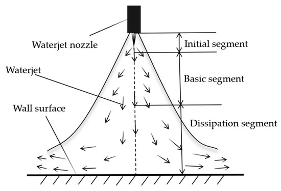
Figure 1.
Schematic diagram of waterjet structure.
The principle of potato peeling using waterjet technology is rooted in the momentum theorem. When the waterjet impacts the potato surface, a portion of its kinetic energy is converted into an impact force—this force generates significant shear stress on the potato’s outer layer, which directly disrupts the internal structural integrity of the potato peel. Simultaneously, the waterjet penetrates the tiny gaps between adjacent skin layers, creating localized high pressure within these gaps. This pressure weakens the bonding force between epidermal tissues and accelerates the initial rupture of the peel structure. For regions where the skin layers are permeable to high-pressure water, the pressure built up by the jet inside the epidermal gaps exceeds the cohesive force between the skin layers, causing the peel to form microcracks that gradually expand outward. Subsequently, the continuous shear and compressive effects of the waterjet further propagate these cracks and fissures across the peel surface, until the entire peel is completely detached from the underlying potato flesh.
To analyze the peeling process from a microscopic perspective, the potato peel is simplified as an assembly of numerous microscopic particles. In this model, the peeling phenomenon is attributed to the propagation of microcracks—these cracks are initiated by defects (e.g., structural inhomogeneities or tiny voids) in the particles surrounding the impact area, and their expansion is driven by the continuous mechanical action of the waterjet. The microscopic model illustrating the interaction between the waterjet and the potato peel is presented in Figure 2.
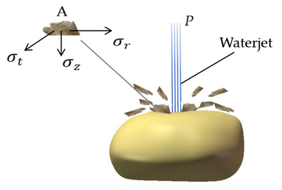
Figure 2.
Schematic of simplified potato peel mechanics.
The impact stress at point A can be calculated by the following formula:
where:
P is operating pressure (MPa);
is radial stress (MPa);
is normal stress (MPa);
is transverse stress (MPa);
As illustrated in Figure 3, when a waterjet impacts the potato surface, the maximum shear stress acts on Region I. Once this shear stress reaches the critical threshold for peel failure, microcracks are initiated in this region. As these initiated cracks propagate along the potato surface, a further increase in the waterjet’s applied load leads to significant stress concentration in Region II—specifically within the range defined by angle β. This localized stress concentration in Region II subsequently drives the partial detachment of the potato peel from the underlying flesh.
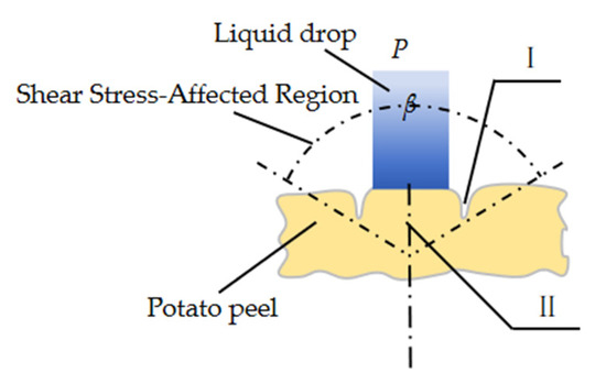
Figure 3.
Schematic of droplet impingement on potato surface.
A waterjet with kinetic energy impacts the potato surface and transfers its energy to the potato peel, which is sufficient to overcome the binding energy between the particles of the potato peel. The energy expression required to break this binding force is as follows:
where:
is the surface energy of the material (J);
is the energy associated with heat and wave propagation (J).
2.2. Determination of Waterjet Nozzle Parameters
In waterjet potato peeling operations, the selection of jet nozzles directly influences three core indicators: peeling efficiency, final product quality, and resource utilization (e.g., water and energy consumption). A rational nozzle selection enables optimized distribution of jet energy, ensuring that key process parameters—including operating pressure, jet flow velocity, and coverage range—fully align with the technical requirements of potato peeling.
As the core executive component of high-pressure waterjet generation systems, nozzles exhibit diverse structural designs. In terms of shape, common types include cylindrical nozzles, fan-shaped nozzles, and conical nozzles. Among these, fan-shaped nozzles stand out for their ability to generate a fan-distributed waterjet: this jet type features a wide coverage area and uniform energy distribution across the impact surface, making it particularly well-suited for direct jet impact on potato surfaces during peeling operations.
2.2.1. Measurement of Potato Geometric Dimensions
The Dutch No.15 potato is a widely cultivated variety, distinguished by a long storage life, large and regular tubers with an elliptical profile, and shallow bud eyes. For this study, 50 mature Dutch No.15 potatoes with intact, undamaged surfaces were selected as test samples to determine their geometric dimensions.
Given the elliptical shape of the potato tubers, their geometric dimensions were calibrated using an ellipsoid-based measurement method. Specifically, a three-axis coordinate system was established with the potato’s geometric center as the origin, and key dimensions measured included the major axis, minor axis, and height (see Figure 4). A vernier caliper with an accuracy of 0.01 mm was used for dimensional measurements.
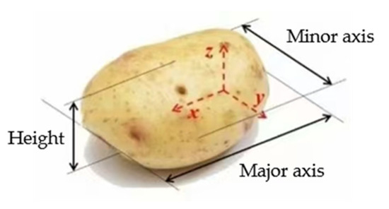
Figure 4.
Geometric dimension calibration of potato specimens.
All measured geometric dimension data were systematically recorded. Subsequently, statistical analysis was performed on the dataset: the distribution range, mean value, and standard deviation of the three parameters (major axis, minor axis, and height) were calculated, and the results are summarized in Table 1.

Table 1.
Geometric dimensions of potato specimens.
2.2.2. Structural Characteristics of the Nozzle
The slot-type fan nozzle features a relatively complex structure at its outlet. The inner side of the nozzle outlet is contracted, with the contraction profile typically being spherical, ellipsoidal, conical, or other shapes. A V-shaped or U-shaped slot, which is perpendicular to the nozzle axis and penetrates the inner surface of the outlet, is machined at the outlet. The structure of a slot-type fan nozzle with a spherical inner surface at the outlet is shown in Figure 5 [28]. Here, D and d represent the diameters of the nozzle inlet and outlet, respectively; L1, L2, and L3 denote the lengths of the inlet section, conical contraction section, and outlet section, respectively; α is the V-shaped slot offset, and α is the half-angle of the V-shaped slot.
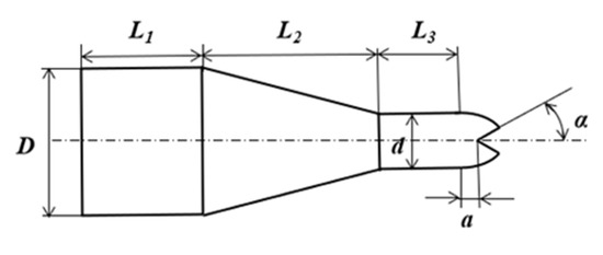
Figure 5.
Internal flow channel structure of V-groove fan-shaped nozzle.
For the fan-shaped nozzle, the waterjet flows out along both sides of the V-shaped groove and diverges, forming a fan-shaped water surface with a certain diffusion angle. This diffusion angle is referred to as the scattering angle θ, as shown in Figure 6 (The dotted line represents the waterjet.).
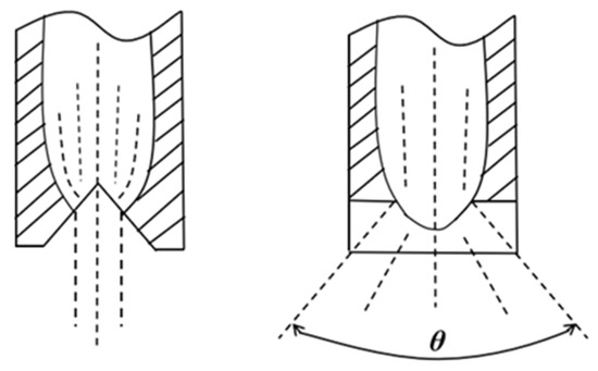
Figure 6.
Schematic diagram of fan nozzle spray.
According to the empirical formula, the relationship between the scattering angle θ and the slot half-angle α is expressed as:
θ = 188.67 − 7.27α + 0.119α2 − 7.99 × 10 − 4α3
This formula indicates that the scattering angle θ decreases with an increase in the slot half-angle α, and conversely, θ increases as α decreases. Table 2 presents the conversion results between the scattering angle θ and the slot half-angle α.

Table 2.
Conversion results between θ and α.
As illustrated in Figure 7, three typical types of high-pressure cleaning fan nozzles are commercially available, characterized by their distinct waterjet scattering angles of 15°, 25°, and 40°, respectively.
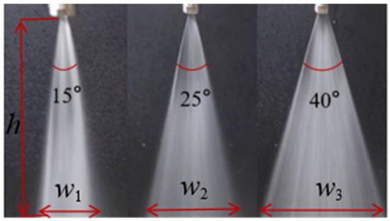
Figure 7.
Spray coverage patterns of fan nozzle at different scattering angles.
Notably, nozzles with different scattering angles exhibit varying jet coverage ranges. The relationship between scattering angles and coverage widths, derived from pre-experiments, is presented in Table 3.

Table 3.
Measured spray coverage at different scattering angles.
In the calibration of potato geometric dimensions, the mean value of the minor axis was determined to be 64.34 mm. Therefore, when selecting a nozzle, attention should be paid to the coverage width of the waterjet to avoid an excessively long or short coverage width.
2.2.3. Numerical Simulation of Nozzles
To investigate the effects of different fan-shaped nozzles on jet parameters, three-dimensional models of nozzles with scattering angles of 15°, 25°, and 40° were established respectively. Using SolidWorks software, a three-dimensional model of the internal flow channel of the fan-shaped nozzle was constructed. A triangular prism transition was set between the internal and external flow fields of the nozzle to achieve better connection between the internal and external fan-shaped jet flow fields. The geometric models of the internal and external flow fields of the nozzle are shown in Figure 8.
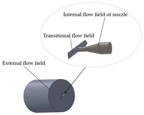
Figure 8.
Diagram of nozzle flow field model.
The three-dimensional model of the fan-shaped nozzle was imported into ANSYS 2022 Workbench, where the model boundaries were named in Mesh and the mesh was generated. In Fluent, the solver type was set to pressure-based, steady-state, and absolute velocity, with the operating environment pressure set to 101,325 Pa. Since the internal and external flow fields of the nozzle contain both water and air, the VOF (Volume of Fluid) model was adopted to solve the split flow layer. The Realizable k-ε turbulence model was selected. The water phase was added from the fluid database, with air as the primary phase and water as the secondary phase. In the interphase interaction, the surface tension coefficient between air and water was set to 72 mN/m. For boundary conditions, the nozzle inlet was defined as a pressure inlet with a total pressure of 7 MPa for the mixed phase. In the solution control parameters, the SIMPLE algorithm was chosen for pressure-velocity coupling; the spatial discretization gradient was set to Least Squares Cell Based, and PRESTO! was selected for pressure discretization. The momentum equation, turbulent kinetic energy, and turbulent dissipation rate were all discretized using the First Order Upwind scheme. After initialization, the iterative calculation was initiated. The velocity contour clouds of the three nozzles are shown in Figure 9. Under a jet pressure of 7 MPa, the outlet flow velocities of the three nozzles obtained from the simulation were 116.81 m/s, 116.10 m/s, and 116.99 m/s, respectively. Based on the nozzle outlet flow velocity calculation formula = , the theoretical outlet flow velocity was determined to be approximately 118.32 m/s. The simulation results were in good agreement with the theoretical calculation results, with a relative error of only 1.5%. This finding verifies the reliability of the simulation results.
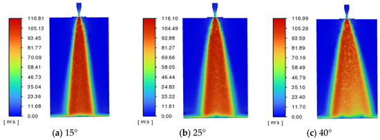
Figure 9.
Velocity contour plots of fan nozzle at different scattering angles.
For the 15° fan-shaped nozzle, the maximum jet velocity was 116.81 m/s, and the velocity at the wall was 93.45 m/s, representing a velocity attenuation of approximately 20%. For the 25° fan-shaped nozzle, the maximum jet velocity was 116.10 m/s, with a wall velocity of 81.27 m/s (attenuated by approximately 30%). For the 40° fan-shaped nozzle, the maximum jet velocity was 116.99 m/s, and the wall velocity was 58.49 m/s (attenuated by approximately 50%). pre-experiments verified that the 15° fan-shaped nozzle exhibited narrow jet coverage and concentrated energy but failed to fully cover the potato surface, resulting in uneven peeling. The 25° fan-shaped nozzle showed moderate coverage and uniform energy distribution, effectively covering the potato surface while avoiding energy waste and flesh damage, making it suitable for potato peeling operations. The 40° fan-shaped nozzle, with its wide coverage and dispersed energy distribution, suffered from insufficient impact force and energy waste, making it suitable for large-area cleaning but not for potato peeling. Considering all factors, the 25° fan-shaped nozzle was selected for waterjet potato peeling in this study.
2.3. Fluid–Structure Interaction Simulation Analysis
2.3.1. Computational Model Construction, Mesh Generation, and Boundary Condition Definition
Potatoes have an ellipsoid-like shape with an uneven surface. In this study, a three-dimensional model of the potato was first established. Using SolidWorks 2022 software, a three-dimensional model of the fan-shaped nozzle was constructed. Figure 10 shows the flow field model of the fan-shaped nozzle jet impacting the potato, where the potato surface serves as the coupling interface.
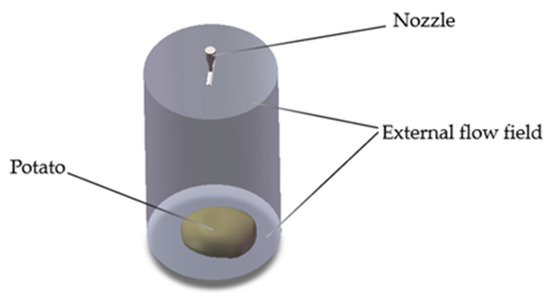
Figure 10.
CFD simulation of waterjet impingement flow field.
The cylindrical end face of the nozzle was set as a pressure inlet boundary condition, with the volume fraction of water specified as 1, meaning the interior of the nozzle was completely filled with water in the initial state. The external flow field region was set as a pressure outlet boundary condition, with the pressure value set to 1 standard atmosphere. All other areas were set as wall boundary conditions. To improve computational accuracy, local mesh refinement was performed for the internal flow channel region of the nozzle. The mesh division of the computational domain is shown in Figure 11.
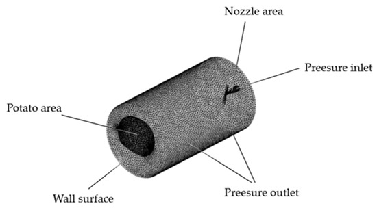
Figure 11.
Computational domain discretization and grid configuration.
2.3.2. Fluid–Structure Interaction Computational Methodology
Numerical simulations essentially involve solving discretized partial differential equations. For fluid flow problems, the solution must satisfy three fundamental conservation laws: mass conservation, momentum conservation, and energy conservation [29], regardless of the jet flow configuration.
The mass conservation equation is expressed as:
The momentum equations in the X, Y, and Z directions are:
where:
p = pressure acting on fluid element
, , = viscous stress components due to molecular viscosity
, , = unit body forces in three directions
The energy conservation equation with temperature T as the variable is:
where:
= specific heat capacity
T = temperature
= thermal conductivity of fluid
= viscous dissipation term (combines internal heat sources and mechanical energy conversion due to viscosity) [30].
The conservation equations derived from Newton’s second law are expressed as:
where:
= solid material density
= Cauchy stress tensor
= body force vector per unit volume
= local acceleration vector in solid domain
Note:
Dimensional analysis verifies the homogeneity of the equation. The unit of the left-hand-side term is kg m−3·m s−2 = N m−3. The units of the right-hand-side terms and are likewise N m−3. The dimensional consistency of the equation is thus confirmed.
Considering the energy transfer during jet impingement, the energy conservation equation is formulated as:
where:
= thermal conductivity of solid material
= energy source term (accounting for heat generation/absorption)
The jet flow from the fan-shaped nozzle exhibits turbulent characteristics, necessitating the adoption of the Realizable k-ε turbulence model. The transport equations for turbulent kinetic energy (k) and its dissipation rate (ε) are formulated as follows:
where:
= turbulence production due to mean velocity gradients
= turbulence generation by buoyancy forces
= compressibility effect on dissipation rate
Model constants: = 1.44, = 0.09, = max [0.43, η/η + 5], = 1.9.
Turbulent Prandtl numbers: = 1.0, = 1.2.
2.3.3. Fluid–Structure Interaction (FSI) Solution Methodology
FSI analysis is a numerical simulation approach that investigates the interaction between fluid flow and structural deformation. It can be categorized into one-way FSI and two-way FSI. One-way FSI involves loading the results of flow field analysis at a specific time point onto the coupling interface for calculation, which is generally applicable when solid deformation is minimal and its influence on the fluid can be neglected. Two-way FSI enables bidirectional data transfer between the fluid and the solid. This study aims to analyze the critical stress state induced on the potato surface by parameters (pressure and standoff distance), with priority given to clarifying the correlation law between the aforementioned parameters and shear stress. In the analysis of jet impact on potatoes, only the effect of fluid stress on the solid needs to be considered; thus, one-way FSI was adopted for the simulation analysis.
First, the fluid domain was solved. In Fluent, the solver type was set to pressure-based, steady-state, and absolute velocity, with the operating pressure set to 101,325 Pa. The VOF model was used to simulate the gas–liquid two-phase flow during the calculation process.
The Realizable k-ε turbulence model was selected. The water phase was added from the fluid database, with air as the primary phase and water as the secondary phase. The surface tension coefficient between air and water was set to 72 mN/m in the interphase interaction. For the solution control parameters, the SIMPLE algorithm was chosen for pressure-velocity coupling; the spatial discretization gradient was set to Least Squares Cell Based, and PRESTO! was selected for pressure discretization. The momentum equation, turbulent kinetic energy, and turbulent dissipation rate were all discretized using the First Order Upwind scheme. The total inlet pressure was set to 3 MPa, 5 MPa, and 7 MPa, respectively. The outlet was configured as a pressure outlet with a pressure of one standard atmosphere. The turbulence intensity is 5%, and the walls are set as no-slip walls.
After initialization, iterative calculations were performed to obtain the pressure distribution in the flow field. The material parameters of potato, including a density of 1051 kg/m3, an elastic modulus of 5 MPa, and a Poisson’s ratio of 0.45, were input into the database. and the results were loaded onto the solid domain. Subsequently, according to the coordination conditions of the coupling interface, the analysis results were transferred to the potato through load transmission for calculation and solution, yielding the final results [31].
2.4. Simulation Experiment Design
The design of the simulation experiment scheme was grounded in pre-experiments, which provided a reliable basis for determining key experimental parameters. A fan-shaped nozzle with a jet scattering angle of 25° was selected as the fixed component, while operating pressure and standoff distance were identified as the two independent experimental factors to investigate their effects on jet performance.
Based on the findings of pre-experiments and the mechanical characteristics of waterjets (e.g., jet impact force attenuation law and flow field stability), the operating pressure was set at three distinct levels (3 MPa, 5 MPa, and 7 MPa), and the standoff distance was configured with three gradient values (100 mm, 200 mm, and 300 mm). The detailed simulation experiment scheme is summarized in Table 4.

Table 4.
Design of simulation experiments.
To eliminate potential systematic errors and ensure the reliability and reproducibility of the simulation results, each group of simulation experiments was repeated three times. Additionally, the simulations for each group were conducted on three different computers to rule out the influence of accidental errors from a single computational platform.
3. Results and Discussion
3.1. Analysis of Simulation Results
To ensure that the accuracy of the simulation results is not affected by grid density, a grid sensitivity analysis was conducted in this study. For a typical working condition (jet pressure: 3 MPa, target distance: 200 mm), three sets of grids with different densities were generated. The maximum shear stress on the potato surface was used as the monitoring variable, and the calculation results are presented in the Table 5 below.

Table 5.
Grid sensitivity analysis results.
The analysis indicates that refining the medium grid to the fine level resulted in a mere 1.44% change in the maximum shear stress, which is below the 2% convergence threshold established in this study, thereby demonstrating that the medium grid resolution is sufficient for obtaining a grid-independent solution.
The number of iterations was set to 1000, with a residual threshold of 1 × 10⁻³ (i.e., 10−3). The residual curve decreased continuously and stabilized at the target threshold when the iteration reached the 315th step, remaining steady without oscillation—indicating that the calculation had achieved convergence (see Figure 12). This confirms the reliability of the results.
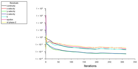
Figure 12.
Residual plot.
The Simulation results are summarized in Table 6. Figure 13 presents the equivalent stress distribution contours of the potato surface under different combinations of standoff distances (100 mm, 200 mm, and 300 mm) and operating pressures (3 MPa, 5 MPa, and 7 MPa). As illustrated in these figures, the radial extent of the jet impact area on the potato surface is relatively larger, whereas the axial extent is relatively smaller. Additionally, the radial equivalent stress on the potato surface exhibits a distinct distribution pattern: it decreases steadily from the center of the impact area to both radial ends, which is consistent with the energy distribution law of fan-shaped waterjet impacts.

Table 6.
Experimental design and corresponding results.
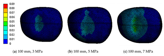
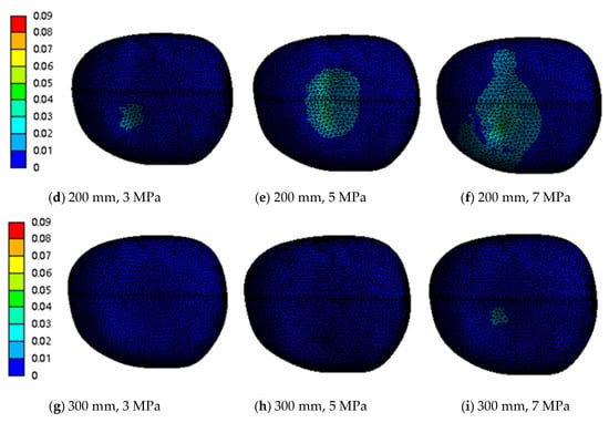
Figure 13.
Contour plot of equivalent stress (Von Mises) distribution.
To precisely evaluate the combined effects of operating pressure and standoff distance on the maximum shear stress on the potato surface, a two-way analysis of variance (ANOVA) was conducted. Prior to the analysis, the assumptions of ANOVA were verified. The Shapiro–Wilk test confirmed the normality of the data (p > 0.05), and Levene’s test indicated homogeneity of variances (p > 0.05).
The results, presented in Table 7, showed that the main effects of both pressure and standoff distance were statistically significant (p < 0.001), and a significant interaction between these two factors was also observed (p < 0.001). The effect sizes (partial η2) revealed that, after controlling for the other factor, pressure alone accounted for 91.8% of the remaining variance in shear stress, standoff distance accounted for 94.9%, and their interaction accounted for 79.3%. According to conventional guidelines, all these effect sizes are considered “very large,” confirming that both parameters and their interaction are decisive factors influencing the shear stress.

Table 7.
Numerical simulation results and ANOVA analysis.
Tukey’s Honest Significant Difference (HSD) post hoc tests were performed to further analyze the significant main effects.
For the pressure factor, all pairwise comparisons between levels were statistically significant (p < 0.01). The maximum shear stress followed the order: 7 MPa > 5 MPa > 3 MPa.
For the standoff distance factor**, all pairwise comparisons were also statistically significant (p < 0.01). The maximum shear stress decreased significantly with increasing distance: 100 mm > 200 mm > 300 mm.
To determine the biomechanical properties of potato peel, a series of experimental tests were conducted following standardized sample preparation and testing protocols. First, samples were harvested from fresh potato peels and machined into rectangular strips with the geometry illustrated in Figure 14a. The standard dimensions of these strips were 40 mm × 15 mm × t mm, where t (representing the peel thickness) varied within the range of 0.3–0.6 mm. Subsequent to sample fabrication, three types of biomechanical tests were performed to evaluate distinct mechanical responses: tensile tests (Figure 14b), tear tests (Figure 14c), and shear tests (Figure 14d).
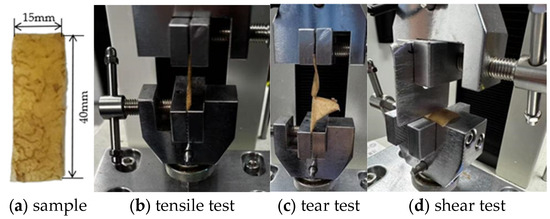
Figure 14.
Photographs of the biomechanical property tests on potato peels.
A constant loading rate of 10 mm/min was adopted for all biomechanical tests, and each test group was replicated five times to ensure the statistical reliability of the experimental data. The results indicated that the tensile strength of potato peels ranged from 0.03 to 0.09 MPa, the tear strength varied between 0.27 N/mm and 0.75 N/mm, and the shear strength was determined to be 0.025–0.038 MPa. Notably, during the waterjet peeling process, potato peels are primarily subjected to shear stress—this mechanical characteristic is the core basis for determining the optimal waterjet parameters. To balance two critical objectives (i.e., achieving effective peeling and minimizing excessive damage to the underlying potato flesh), it is therefore essential to control the shear stress induced by the waterjet within the range of 0.025–0.04 MPa. This range incorporates a 5% floating margin, which accounts for inevitable variations in potato peel thickness (0.3–0.6 mm, as previously noted) and ensures robust performance across different samples.
Figure 15 shows the shear stress distribution contours under the conditions of standoff distances of 100 mm, 200 mm, and 300 mm, and operating pressures of 3 MPa, 5 MPa, and 7 MPa, respectively.
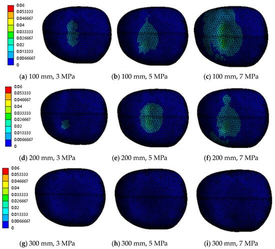
Figure 15.
Contour mapping of shear stress (τ) distribution.
As can be seen from the figures, when the standoff distance is 200 mm and the operating pressure is 3 MPa, the maximum shear stress on the potato surface is 0.013381 MPa, which is too low to achieve the peeling effect. At an operating pressure of 7 MPa, the maximum shear stress on the potato surface is approximately 0.05237 MPa, which is excessively high and prone to causing significant damage to the potato flesh. In contrast, at an operating pressure of 5 MPa, the maximum shear stress on the potato surface is 0.030 MPa, which meets the basic requirements for potato peeling while avoiding excessive damage to the potato flesh.
3.2. Influence of Different Factors on Maximum Shear Stress
As evidenced in Figure 16, when the standoff distance is in the range of 100 mm to 200 mm, the momentum transfer field formed by the high-pressure jet through the nozzle interacts with the boundary layer on the potato surface. Within this standoff distance range, the energy density of the jet core region and the flow field diffusion constrained by the target reach a dynamic equilibrium, stabilizing the shear stress within the range of 0.026–0.038 MPa. However, when the standoff distance increases to 300 mm, the jet beam undergoes energy attenuation due to air entrainment and turbulent dissipation, and the flow field morphology changes from “concentrated impact” to “diffusive scouring”, resulting in an order-of-magnitude decrease in shear stress. Compared with the standoff distance of 100 mm, the stress attenuation exceeds 60%. Therefore, the optimal range of standoff distance is determined to be 100–200 mm to maintain the effective action range of shear stress.
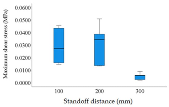
Figure 16.
Relationship between standoff distance and maximum shear stress.
As indicated in Figure 17, operating pressure, as the core parameter of energy input, exhibits a piecewise linear response characteristic with shear stress. When the pressure is 3 MPa, the jet energy is lower than the “shear activation threshold” of potato peel, and the stress response is in an inefficient range (<0.02 MPa). When the pressure is increased to 5 MPa, the energy input matches the shear strength of the potato peel, and the stress jumps to the edge of the target range (0.03–0.04 MPa). When the pressure is further increased to 7 MPa, the energy input exceeds the “shear-damage coupling threshold” of the potato peel, leading to stress runaway (exceeding 0.05 MPa). Through threshold effect analysis, the optimal operating pressure is determined to be 5 MPa.
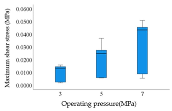
Figure 17.
Relationship between operating pressure and maximum shear stress.
Verification was performed on the combinations of standoff distances of 100 mm, 200 mm and an operating pressure of 5 MPa. As shown in Figure 18, according to the data trend, when the standoff distance is 200 mm, the average value of shear stress is closer to the median of the target range. Compared with the standoff distance of 100 mm, its stress stability and adaptability to the target range are better. From the perspective of multi-parameter coupling optimization, the parameter combination of a standoff distance of 200 mm and an operating pressure of 5 MPa can make the shear stress stably fall into the target range of 0.025–0.04 MPa, forming an optimal parameter scheme under this stress constraint scenario.
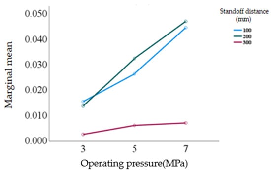
Figure 18.
Combined effects of operating pressure and standoff distance on maximum shear stress.
3.3. Verification Experiments
To further validate the peeling efficacy of waterjet technology, verification experiments were conducted under the conditions of standoff distances of 100 mm, 200 mm, and 300 mm, and operating pressures of 3 MPa, 5 MPa, and 7 MPa, respectively. A photographic illustration depicting the experimental setup for waterjet peeling is presented in Figure 19.
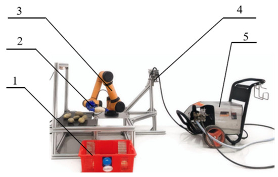
Figure 19.
Photographic illustration of the on-site experiment. 1. Potato collection basket, 2. End effector, 3. Robotic arm, 4. waterjet nozzle, 5. waterjet generating device.
The robotic arm moved with high precision to the target position as instructed. Its end effector—depicted in Figure 20a—firmly gripped the potato and guided it through the waterjet nozzle at a steady, constant speed (20 mm/s) for peeling, as shown in Figure 20b. Following this initial peeling step, the sixth axis of the robotic arm rotated 180°, enabling the potato to pass through the waterjet a second time; this double-pass process ensured the potato was peeled thoroughly. Once peeling was complete, the robotic arm placed the potato into the collection basket. During the operation, the operating pressure was adjusted using a plunger pump (see Figure 20c), while the standoff distance between the nozzle and the potato was precisely regulated by the robotic arm itself.
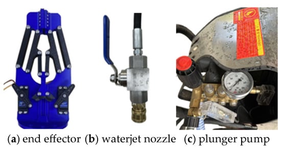
Figure 20.
Photographic images of partial experimental setups.
Experimental comparisons showed that the peeling effect was better when the standoff distance was set to 200 mm and the operating pressure was 5 MPa. Under this parameter combination, the process not only effectively removed potato peels—even those in hard-to-reach areas like eyes and concave surfaces—but also caused no visible damage to the potato flesh. In contrast, when the operating pressure was adjusted to 3 MPa, the peeling effect was insignificant, with residual peel still remaining on the potato surface. Conversely, increasing the operating pressure to 7 MPa led to more obvious damage to the potato flesh. The experimental results corresponding to these different parameter conditions are presented in Figure 20. The experimental results also verified that the simulated trend of shear stress decreasing with increasing standoff distance and increasing with rising jet pressure agrees well with actual observations.
Additionally, hyperspectral imaging was employed to capture spectral images of the potatoes after peeling (see Figure 21). The two figures show the spectral curves of potato flesh and potato peel after peeling, respectively, with each figure containing 100 sets of spectral curve data. The optimal characteristic wavelength band (592 ± 20 nm) was identified by analyzing reflectance curves and applying Principal Component Analysis (PCA). This band was then integrated with image processing techniques and a double-threshold segmentation method to calculate the peeling rate.
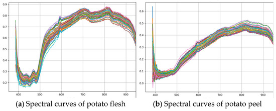
Figure 21.
Spectral Characteristic Curves of Potato Tissues.
In this study, the peeling rate is defined as the ratio of the number of pixels in the potato flesh area to the total number of pixels representing the potato. This definition is based on the assumption that the flesh area consists exclusively of peeled potato tissue, while the peel area contains any remaining epidermal parts. Since the peeling rate represents the ratio of the peeled surface area to the total surface area of the potato, a higher peeling rate indicates better peeling effectiveness.
Thus, the peeling rate (PR) is calculated using the following formula:
where:
: Number of pixels classified as flesh in the frontal image
: Number of pixels classified as flesh in the dorsal image
: Total number of pixels in the frontal image
: Total number of pixels in the dorsal image
The flesh loss rate (LR) was determined gravimetrically using the following formula:
where:
: represents the total weight of the potato before peeling;
: denotes the weight of the flesh after peeling;
is the theoretical weight of the peel, estimated as × 2%.
The experimental results demonstrate that this method can accurately distinguish between the peel and the flesh. The quantitative results under different parameters are as follows: At a standoff distance of 200 mm and a jet pressure of 3 MPa, the average peeling rate was 87.5% with a flesh loss rate of 1.1%. When the pressure was increased to 5 MPa, the average peeling rate reached 97.9%, accompanied by a flesh loss rate of 1.8%. Under the condition of 200 mm and 7 MPa, the average peeling rate was 99.2%, with a flesh loss rate of 6.1%. The experimental results corresponding to these different parameter conditions are presented in Figure 22. These results collectively demonstrate that the parameter combination of a 200 mm standoff distance and a 5 MPa jet pressure yielded a higher peeling rate with a lower flesh loss rate compared to other tested parameters. This further confirms the superior performance of the 200 mm standoff distance and 5 MPa jet pressure combination.
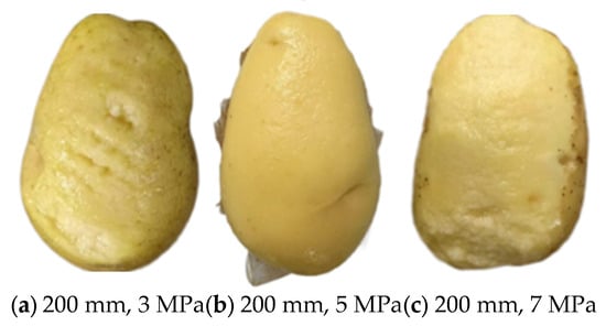
Figure 22.
Photographic images of experimental results.
4. Conclusions
In this study, Ansys software was employed to simulate the external flow field of nozzles with different scattering angles. Additionally, a one-way fluid–structure interaction (FSI) simulation was conducted on the nozzle jet-potato model to analyze the stress distribution on the potato surface, thereby initially determining the optimal experimental parameter combinations. The main conclusions are summarized as follows:
- (1)
- The fan-shaped nozzle with a scattering angle of 25° not only satisfies the requirement of low velocity attenuation during the jet process but also ensures a sufficient jet coverage area on the potato surface, laying a foundation for efficient peeling.
- (2)
- Within the jet impact zone, the radial length is longer, while the axial length is shorter. Specifically, the distribution of radial equivalent stress on the potato surface exhibits a regular pattern of steady decrease from the central area of the impact zone to both ends, which provides a theoretical basis for understanding the force characteristics of the potato during peeling.
- (3)
- The parameter combination—including a waterjet scattering angle of 25°, a standoff distance of 200 mm, and the operating pressure of 5 MPa (referring to the working pressure of a piston pump)—fully meets the basic technical requirements for waterjet potato peeling. More importantly, this combination can effectively avoid excessive damage to the potato flesh, balancing peeling efficiency and product quality.
The innovation of this study lies in two aspects: first, the proposal of a “parameter optimization method based on the shear strength threshold of potato peel,” which integrates fluid–structure interaction simulation with the mechanical properties of potato peel to achieve precise design of peeling parameters; second, the validation of the applicability of fan-shaped nozzles in the peeling of tuber-based agricultural products.
However, this study also has certain limitations. The one-way fluid–structure interaction analysis conducted in this study is a steady-state simulation, which mainly focuses on the relationship between jet parameters and the surface stress of potatoes. The effects of the dynamic impact process and the cumulative effect of action time are not considered herein.
The current experimental setup, employing a single nozzle combined with a robotic arm, is inadequate for large-scale production. Additionally, the experiments were conducted only on a specific potato variety (Helan 15), and thus the generalizability of the findings requires further verification. Regarding the optimization method, the current approach belongs to parameter screening rather than systematic optimization. At present, the parameter grid is relatively sparse, which may lead to the omission of the optimal intermediate values.
Based on these limitations, future research directions are proposed, such as: conducting peeling parameter studies on different potato varieties; designing and developing a prototype of continuous waterjet peeling equipment suitable for industrial production, followed by energy consumption and cost–benefit analysis. Furthermore, conducting transient fluid–structure interaction analysis to investigate the dynamic relationship between water jet exposure time and peeling effectiveness has been identified as a key focus for future research. We will systematically study the quantitative correlation between exposure duration and both peel removal rate and flesh loss rate. In future work, we will further adopt the response surface methodology (RSM) to explore a robust operating window within a more refined parameter space, rather than focusing solely on a single optimal point.
Author Contributions
Conceptualization, H.H. and Y.W.; methodology, H.H., S.Z., L.Z. and Y.W.; software, Y.S.; validation, Y.S., G.C. and Q.Z.; formal analysis, S.Z., Y.W. and Q.Z.; investigation, G.C. and Q.Z.; resources, L.Z.; data curation, Y.S.; writing—original draft preparation, Y.S.; writing—review and editing, H.H.; visualization, G.C.; supervision, S.Z., L.Z., Y.W., G.C. and Q.Z.; project administration, S.Z. and L.Z.; funding acquisition, H.H. All authors have read and agreed to the published version of the manuscript.
Funding
This research was funded by National Natural Science Foundation of China, grant number 52205295 and Research and Application Demonstration of Mechanized Production Technology for Tuber Crops in Lingnan Region, grant number KA21031D9.
Institutional Review Board Statement
Not applicable.
Data Availability Statement
The original contributions presented in this study are included in the article. Further inquiries can be directed to the corresponding author.
Acknowledgments
The authors would like to express sincere gratitude to Zhongkai University of Agriculture and Engineering for its valuable support and assistance provided during the experimental phase.
Conflicts of Interest
The authors declare no conflicts of interest.
References
- Shen, C.K. Preparation and Application of Raw Potato Flour. Master’s Thesis, Jiangnan University, Wuxi, China, 2016. [Google Scholar]
- Yue, X.; Qu, J.; Guo, Y. Current Status, Influencing Factors, and Countermeasures of China’s Potato Industry. Agric. Outlook 2016, 11, 55–58. [Google Scholar]
- He, J. Overview and Reflections on the Development of the Potato Industry in Guangdong Province. Bull. Agric. Sci. Technol. 2016, 12, 4–6. [Google Scholar]
- Chen, H.; Liu, Q. Research Progress in Potato Peeling Technology. Food Ind. 2016, 37, 229–232. [Google Scholar]
- Li, S.Z. Research on Key Technology and Experimental Optimization of Vertical Cylinder-Type Potato Peeling. Master’s Thesis, Zhongkai University of Agriculture and Engineering, Guangzhou, China, 2019. [Google Scholar]
- Cao, G.; Du, Z.; Cheng, Y.; Lu, T.; Li, P.; Cheng, D. Research Progress and Prospect of Peeling Technology and Equipment for Tuber Crops. Agric. Eng. 2020, 10, 8–14. [Google Scholar]
- Garrote, R.; Silva, E.; Bertone, R. Effect of thermal treatment on steam peeled potatoes. J. Food Eng. 2000, 45, 67–76. [Google Scholar] [CrossRef]
- Peter, V.; Shen, X. Potato Steam Peeling System of Gouda Company in the Netherlands. Farm Prod. Process. 2003, 5, 32–35. [Google Scholar]
- Chand, K.; Pandey, R.; Shahi, N.; Lohani, U. Pedal operated integrated potato peeler and slicer. AMA-Agric. Mech. Asia Afr. Lat. Am. 2013, 44, 65–68. [Google Scholar]
- Zong, W.Y. Research on Potato Peeling Technology. Master’s Thesis, Huazhong Agricultural University, Wuhan, China, 2001. [Google Scholar]
- Chen, S. Research on Chemical Peeling Technology of Potatoes. Hunan Agric. Sci. 1998, 4, 39–40. [Google Scholar]
- Henning, A. Cutting with high-pressure jet in the food industry. Fleischwirtschaft 1998, 78, 43–45. [Google Scholar]
- Wulfkuehler, S.; Dietz, J.; Schmidt, H.; Weiss, A.; Carle, R. Quality of fresh-cut radicchio cv. Rosso di Chioggia (Cichorium intybus L. var. foliosum Hegi) as affected by water jet cutting and different washing procedures. Eur. Food Res. Technol. 2015, 240, 159–172. [Google Scholar] [CrossRef]
- Hägele, F.; Nübling, S.; Schweiggert, R.M.; Nolte, L.; Weiss, A.; Schmidt, H.; Carle, R. Comparison of ultra-high-pressure water jet and conventional rotating blade cutting for the production of fresh-cut iceberg (Lactuca sativa L.) and endive (Cichorium endivia L.). Eur. Food Res. Technol. 2016, 242, 2071–2081. [Google Scholar] [CrossRef]
- Thanomputra, S.; Kiatiwat, T. Simulation study of cutting sugarcane using fine sand abrasive waterjet. Agric. Nat. Resour. 2016, 50, 146–153. [Google Scholar] [CrossRef]
- Liu, H.; Wang, Z.; Cheng, M.; Xu, W.; Liu, H.; Yu, X.; Zhi, S. Development and Application Status of High-Pressure waterjet Cutting Technology. Mach. Tool Hydraul. 2018, 46, 173–179. [Google Scholar]
- Carreño-Olejua, R.; Hofacker, W.C.; Hensel, O. High-pressure water-jet technology as a method of improving the quality of post-harvest processing. Food Bioproc. Technol. 2010, 3, 853–860. [Google Scholar] [CrossRef]
- Zhao, Z.; Yu, C.; Zhong, J.; Huang, J.; Zhang, X. Numerical Simulation of Continuous Non-Submerged waterjet Vibration Cleaning Process for Granular Agricultural Products. Trans. Chin. Soc. Agric. Mach. 2018, 49, 331–337. [Google Scholar]
- Wang, J.; Yang, S.; Xie, Q.; Yi, J. Experiment and Parameter Optimization of waterjet Stripping Scallop Adductor Muscle. Trans. Chin. Soc. Agric. Eng. 2017, 33, 289–294. [Google Scholar]
- Wu, H. Working Mechanism and Experimental Research of Jet-Spinning Lotus Root Digging Machine. Master’s Thesis, Huazhong Agricultural University, Wuhan, China, 2018. [Google Scholar]
- Xu, X.; Ding, W.; Zhang, W.; Liu, M. Design and Parameter Optimization of Fresh Lotus Seed Peeling Machine. Trans. Chin. Soc. Agric. Mach. 2021, 52, 338–349. [Google Scholar]
- Zhang, Y.; Cao, Y.; Lu, H.; Yang, Y. Experiment and Simulation of High-Pressure waterjet Cleaning on Ship Surfaces. Ship Ocean. Eng. 2020, 49, 86–89. [Google Scholar]
- Sun, Y. Deep Cleaning Technology and Equipment Design for Sea Cucumbers Based on Waterjet. Master’s Thesis, Dalian Polytechnic University, Dalian, China, 2019. [Google Scholar]
- Liu, H.F. Simulation Study of Fan Nozzle for High-Pressure Waterjet in Licorice Cleaning. Master’s Thesis, Lanzhou University of Technology, Lanzhou, China, 2016. [Google Scholar]
- Chen, M.M. Research and Development of Multi-Model Mobile Phone Appearance Cleaning and Inspection Equipment. Master’s Thesis, Zhejiang University, Hangzhou, China, 2021. [Google Scholar]
- Leu, M.-C.; Meng, P.; Geskin, E.; Tismeneskiy, L. Mathematical modeling and experimental verification of stationary waterjet cleaning process. J. Manuf. Sci. Eng. 1998, 120, 571–579. [Google Scholar] [CrossRef]
- Sun, J.J. Waterjet Cutting Technology; China University of Mining and Technology Press: Xuzhou, China, 1992. [Google Scholar]
- Ren, X.Z. Structure and Wear Study of Fan Nozzles for High-Pressure Waterjet Cleaning. Master’s Thesis, Central South University, Changsha, China, 2009. [Google Scholar]
- Ren, W. Numerical Simulation of Resistance Coefficient in Porous Media of Gob Areas. Master’s Thesis, Taiyuan University of Technology, Taiyuan, China, 2013. [Google Scholar]
- Tang, L.; Ye, F.; Gong, F.; Qian, K. Application of Turbulence Model in Shell-Side Structure Optimization of Baffled Heat Exchangers. Anhui Univ. (Nat. Sci. Ed.) 2015, 39, 62–67. [Google Scholar]
- Shi, W.; Wang, G.; Zhang, D.; Jiang, X.; Xu, Y. Stress Characteristics of Axial Flow Pump Blades Based on Fluid-Structure Interaction. Drain. Irrig. Mach. Eng. 2013, 31, 737–740. [Google Scholar]
Disclaimer/Publisher’s Note: The statements, opinions and data contained in all publications are solely those of the individual author(s) and contributor(s) and not of MDPI and/or the editor(s). MDPI and/or the editor(s) disclaim responsibility for any injury to people or property resulting from any ideas, methods, instructions or products referred to in the content. |
© 2025 by the authors. Licensee MDPI, Basel, Switzerland. This article is an open access article distributed under the terms and conditions of the Creative Commons Attribution (CC BY) license (https://creativecommons.org/licenses/by/4.0/).