Abstract
To address the issues of high stalk breakage rate and the mismatch between extraction force and operational speed in current horizontal shaft counter-rolling cotton stalk pullers, this study presents a novel clamping mechanism. The mechanism enables precise adjustment of the rollers’ rotational speed, inter-roller gap, and surface topography. The objective is to systematically investigate the effects of these key parameters on the peak extraction force and its timing during the stalk pulling process. Initially, pre-compressed cotton stalks were employed as test specimens. Their tensile properties post-compression were investigated by simulating the extraction forces using a universal testing machine. Subsequently, the structural design of the critical components for the test rig was created based on these experimental findings. Theoretical analysis identified the surface texture of the clamping rollers, their rotational speed, and the clamping gap as the primary experimental factors. The effects of these factors on the peak extraction force and its timing were analyzed using Response Surface Methodology (RSM). The results indicated that the optimal combination—striped surface texture for both rollers, a speed of 220 rpm, and a zero gap—yielded a time to peak force of 0.05 s and a peak force of 710.77 N, which is significantly below the measured tensile strength limit of 994.60 N for compressed stalks. This indicates that the designed clamping device for the horizontal shaft counter-rolling cotton stalk extraction machine achieves faster extraction speed while ensuring stalk integrity, and the research results can provide theoretical foundation and design guidance for the development of horizontal shaft counter-rolling cotton stalk extraction machinery.
1. Introduction
China is one of the world’s leading cotton-producing nations, with Xinjiang accounting for 86% of its total cotton production [1]. Cotton stalks, a major by-product of cotton cultivation, possess versatile potential for applications including biomass fuel, construction materials, paper manufacturing, and animal feed [2,3,4,5,6,7]. The resource utilization of cotton stalks is crucial for enhancing farmers’ income and fostering the sustainable development of the cotton industry. Research into the mechanization of cotton stalk harvesting is fundamental to advancing this resource utilization process. Currently, the predominant management practice involves directly shredding and incorporating cotton stalks into the soil (in situ). This practice presents several challenges: the slow degradation rate of the stalks impedes sowing operations and restricts root development in subsequent cotton crops [8,9,10]; they can harbor pathogens and insect eggs, increasing the risk of disease and pest infestations [11]; and the intermingling of shredded stalks with residual plastic mulch film complicates film retrieval and post-processing. In contrast, a whole-stalk extraction method, which uproots the stalks, effectively avoids these aforementioned drawbacks and significantly increases the total biomass yield available for utilization. Consequently, research focused on whole-stalk extraction machinery is highly valuable for promoting the resource utilization of cotton stalks.
Researchers worldwide have conducted extensive studies on whole-stalk cotton stalk extraction. Studies abroad primarily utilize the counter-roller extraction principle, with research in this area dating back to the 1980s. Sumner et al. [12] developed a wheel-type cotton stalk extraction device and optimized its operational parameters by investigating the effects of the extraction angle, the air pressure of the clamping wheels, and the rotational speed of the clamping wheels on the extraction force; Alamgir et al. [13] designed a combined machine for cotton stalk extraction and seeding. They improved the surface treatment of the extraction components based on the load analysis of critical force-bearing parts during operation, which enhanced the reliability of the extraction mechanism; Ramadan et al. [14] developed a vertical shaft counter-rolling cotton stalk extraction device. They optimized its working parameters by analyzing the effects of the vertical shaft angle and the rotational speed on the stalk extraction rate. Although foreign cotton planting patterns differ from domestic ones, and consequently, foreign machine designs are incompatible with the widely adopted Chinese wide-narrow row pattern (660 mm + 100 mm) for mechanized cotton harvesting, the research methodologies and findings from international studies on the counter-roller extraction principle demonstrate its fundamental feasibility and provide valuable insights for reference.
Researchers in China have investigated various mechanisms for whole-stalk cotton stalk extraction. These mechanisms can be categorized by their working principles into counter-roller, toothed-plate, and chain/belt clamping types. The counter-roller type is further divided into horizontal shaft and vertical shaft configurations. The toothed-plate type encompasses roller-gear and disc-gear designs, while the chain/belt clamping type includes chain-gear and belt-clamping systems. The research team led by Zhang Jiaxi at Xinjiang Agricultural University has developed multiple cotton stalk extraction devices, such as a toothed-plate stalk lifting device, a belt-clamping extraction device, and a horizontal shaft counter-roller extraction device [15,16,17]. Ablikim Abdukerim et al. [18] developed a coaxial counter-rotating rubber roller stalk extractor. Chen Mingjiang from the Chinese Academy of Agricultural Sciences designed a disc-gear stalk pulling device [19]. He Xiaowei et al. from China Agricultural University developed a 4MB-6 model inline shovel-lift and windrower for densely planted cotton stalks [20]. Wang Jikui et al. from Shihezi University invented a horizontal lying roller-type stalk extraction device [21]. In summary, the horizontal shaft counter-rolling mechanism offers distinct advantages over other extraction methods, primarily lower requirements for precise row alignment and superior adaptability for large-scale stalk harvesting under the “one film covering six rows” planting pattern. To date, domestic researchers have extensively investigated the effects of key operational parameters—such as roller rotational speed, extraction angle, and forward speed of the implement—on the extraction efficiency of horizontal shaft counter-rolling extractors. Optimal operational speed ratios for the key components compatible with this principle have been established. However, a significant challenge persists: the intense compression applied by the clamping rollers at the grip point damages the stalk’s structure, reducing its tensile strength and resulting in a high stalk breakage rate. Concurrently, managing the magnitude of the extraction force often leads to an incompatibility with the extraction speed, causing stalk slippage or incomplete extraction (missed stalks). Moreover, the effect of the clamping rollers’ surface texture on the extraction force remains an understudied area in current research.
Accordingly, building upon the research into the tensile strength of compressed cotton stalks, this study designs a novel clamping mechanism for a horizontal shaft counter-rolling cotton stalk extraction machine. The focus is on the structural design of this clamping mechanism. The operational parameters are optimized using the extraction force and the time to peak force as key evaluation metrics. This work aims to investigate the influence of altering key operational parameters on the extraction force and its temporal characteristics (time to peak). The goal is to enable the clamping mechanism to deliver a higher extraction force and a faster extraction speed while preventing stalk breakage, thereby laying a foundation for the development of horizontal shaft counter-rolling cotton stalk extraction machinery.
2. Materials and Methods
2.1. Investigation into the Mechanical Properties of Cotton Stalk Clamping
During the complete extraction process, the extraction force exerted on the cotton stalk is generated by the normal pressure () from the upper and lower clamping rollers. The combination of this normal force and the rotational motion of the rollers induces a frictional force () acting along the stalk’s axis in the direction away from the ground. This frictional force constitutes the primary source of the extraction force. The relationship between the normal force and the frictional force is given by Equation (1).
Preliminary field measurements indicated that the extraction resistance of cotton stalks falls within the range of 280.25 N to 410 N. To guarantee successful stalk extraction, a design extraction resistance of 500 N was adopted, resulting in 500 N. Given a coefficient of friction f of 0.5 between rubber and the cotton stalk surface, substitution into Equation (1) calculates the maximum required normal pressure from the clamping rollers on the stalk to be 1000 N. However, the compressive force applied by the rollers can damage the internal structure of the stalk, which directly compromises its tensile strength. Therefore, to achieve successful whole-stalk extraction and prevent stalk fracture during the clamping phase, it is essential to investigate the tensile strength of cotton stalks under clamping conditions. This research provides the fundamental basis for the design parameters of the clamping rollers.
The tensile strength of cotton stalks post-compression was investigated following the methodologies outlined in GB/T 1939-2009 “Test method for transverse compression of wood” [22], GB/T 1938-2009 “Test method for tensile strength parallel to grain of wood” [23], and supplementary literature. Radial compression and subsequent tensile strength tests were performed on cotton stalk specimens using an Instron E1000 and a 34TM-10 universal material testing machine(China), as illustrated in Figure 1. To simulate the clamping action of the rollers during field operation, a compression test was first conducted at a loading rate of 200 N/s until a force of 1000 N was reached. Following this compression, a tensile test was performed on the compressed stalk specimens at a crosshead speed of 10 mm/min to determine their residual tensile strength. The experimental results indicated that the tensile strength of untreated cotton stalks ranged from 23.95 MPa to 33.25 MPa. After being rapidly compressed with a 1000 N force, the tensile strength significantly decreased to a range of 17.93 MPa to 23.51 MPa. To ensure stalk integrity and prevent breakage in subsequent mechanical design, the conservative minimum post-compression tensile strength value of 17.93 MPa was adopted. This value corresponds to a maximum allowable extraction force of 994.60 N, which served as the critical design criterion for the following key structural parameters.
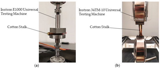
Figure 1.
Cotton stalk force analysis diagram. (a) Cotton stalk compression process. (b) Cotton stalk stretching process.
2.2. Overall Structural Design
The integrated structure of the clamping mechanism for the horizontal shaft counter-rolling cotton stalk extraction machine comprises five main subsystems: the stalk clamping mechanism, the floating adjustment mechanism for the clamping rollers, the drive system, the extraction force measurement system, and the main frame. The stalk clamping mechanism incorporates an upper and a lower clamping roller. The floating adjustment mechanism for these rollers primarily includes a hinged bearing block baseplate, compression springs, and threaded adjustment rods. The drive system is mainly constituted by independent hydraulic motors for the upper and lower extraction rollers. The extraction force measurement system employs an S-type tension load cell and a corresponding data acquisition circuit, as depicted in Figure 2. The floating adjustment mechanisms for the clamping rollers are secured to both sides of the main frame using spring-screw assemblies. The upper clamping roller is mounted at its ends, via bearing blocks, onto these floating adjustment mechanisms on each side of the frame. The lower clamping roller is similarly mounted via bearing blocks at the base of the frame, positioned directly below the upper roller. Each clamping roller is directly coupled to its respective hydraulic motor. These hydraulic motors are connected to a hydraulic power unit (pump) through hoses and a flow control valve (speed regulator), enabling precise adjustment of the rollers’ rotational speeds by modulating the hydraulic flow rate. The tension load cell from the force measurement system is attached to the frame with a pivotal (hinged) connection. The data acquisition circuit interfaces with a computer, facilitating the real-time recording of the tensile force applied to the cotton stalk during the extraction process.
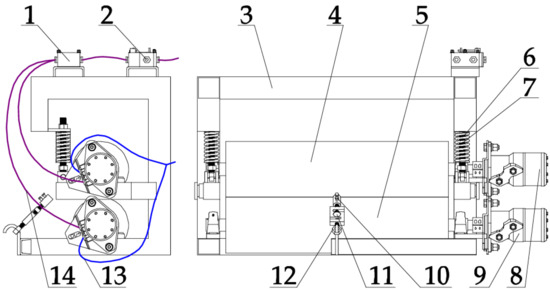
Figure 2.
General Configuration Schematic of the Clamping Mechanism. 1: Synchronizing Valve. 2: Flow Control Valve. 3: Main Frame. 4: Upper Clamping Roller. 5: Lower Clamping Roller. 6: Spring. 7: Threaded Rod. 8: Hydraulic Motor for Upper Roller. 9: Hydraulic Motor for Lower Roller. 10: Cotton Stalk Fixing Sleeve. 11: S-type Tension Load Cell. 12: S-type Tension Load Cell. 13: Return Oil Line. 14: Inlet Oil Line.
The main technical parameters of the clamping device for the horizontal shaft counter-rolling cotton stalk extraction machine are presented in Table 1.

Table 1.
Main technical parameters.
2.3. Principle of Operation
During operation, the counter-rotating hydraulic motors drive the upper and lower clamping rollers to rotate in opposite directions. The rotational speed of these rollers is precisely controlled by adjusting the flow regulator. The clamping gap width is set by modifying the spring preload length in the floating adjustment mechanism attached to the upper roller. Operators manually feed the top portion of the cotton stalk into this gap between the rollers. The rotation of the rollers engages and pulls the stalk, applying the extraction force. The S-type tension load cell detects this force, converts it into an electrical signal, and the data acquisition system transmits this signal in real time to a computer. This setup allows for the precise collection of time-varying tensile force data experienced by the cotton stalk during the complete extraction cycle.
2.4. Design of the Cotton Stalk Clamping Mechanism
The stalk clamping mechanism, which functions to grip the cotton stalk and apply the necessary extraction force for whole-plant removal, represents the core component of the horizontal shaft counter-rolling cotton stalk extraction machine’s clamping device. It primarily comprises the upper clamping roller and the lower clamping roller.
To accommodate experimental requirements and align with the prevalent “660 mm + 100 mm” wide-narrow row cotton planting pattern in Xinjiang, the working width of the mechanism was designed to be 800 mm, as illustrated in Figure 3. The surface of the clamping rollers is textured with a striped pattern and fabricated from natural rubber material.
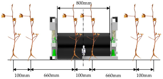
Figure 3.
Schematic Diagram of the Clamping Width.
2.4.1. Determination of the Clamping Roller’s Rotational Radius
As illustrated in Figure 4, the forces acting on the cotton stalk at the clamping point mainly include the normal clamping force, the resulting frictional force, and the stalk’s extraction resistance from the soil. The existence of the wrap angle (α) creates complex, multi-directional force vectors, precluding analysis based on a single point of application. Therefore, this study utilizes the Euler-Eytelwein formula, a standard approach in friction mechanics, for the analysis. Defining as the total axial tensile force applied to the stalk, the limiting condition for successful whole-stalk extraction is expressed by the following equation:
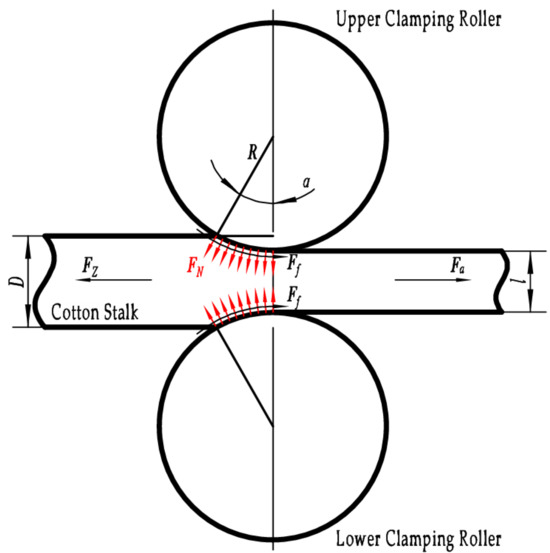
Figure 4.
Structural and Mechanical Force Schematic of the Clamping Mechanism.
In the equation, represents the total axial tensile force (unit: N); denotes the extraction resistance (unit: N); f is the coefficient of friction, assigned a value of 0.5; and α signifies the wrap angle (unit: rad).
The force analysis presented in the preceding section established that the total axial tensile force () must remain below the ultimate tensile force of the compressed cotton stalk, which is 994.60 N. Consequently, to prevent stalk breakage during the clamping operation, the following condition must also be satisfied:
The geometric relationship depicted in Figure 4 allows for the derivation of a trigonometric expression relating the cotton stalk diameter (D), the gap (l) between the rollers, and the radius (R) of the clamping rollers:
By substituting the coefficient of friction f = 0.5 and the extraction resistance = 500 N into the simultaneous solution of Equations (2)–(4), the minimum required clamping roller radius is determined to be R > 8.706 mm.
Equation (5) indicates that the required driving torque increases with the rotational radius under a constant rotational load. As established in the foregoing analysis, a tangential frictional force of 500 N acts on the surface of the operational clamping rollers. Employing a standard BM2-50 hydraulic motor as the power source, which provides an actual working output torque of 114 N·m, and incorporating a safety margin for operational loads, a design torque of 100 N·m is utilized. This calculation determines the maximum allowable rotational radius for the clamping rollers to be = 200 mm, establishing the permissible range: 8.706 mm < R < 200 mm. Based on a comprehensive evaluation of overall machine size and assembly constraints, a radius of R = 100 mm was ultimately selected.
2.4.2. Determination of the Clamping Roller’s Operational Speed
Literature sources [24,25,26] indicate that the operational forward speed of the implement and the rotational speed of the clamping rollers are critically important for the efficiency of cotton stalk extraction. To guarantee the validity of the extraction force measurements, the rotational speed of the clamping rollers must be designed in accordance with realistic field operating conditions. The “Agricultural Machinery Design Handbook” [27] establishes that the motion of the clamping rollers during operation is synthesized from their rotational movement around the roller shaft and the translational forward movement of the implement. The kinematic equation describing this combined motion is as follows:
In the equation, represents the forward speed of the implement (unit: m/s); H denotes the height of the clamping gap from the ground (unit: m).
The resulting motion path, illustrated in Figure 5, follows a trochoidal curve.
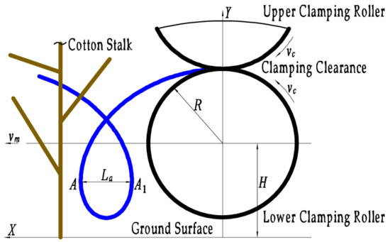
Figure 5.
Path Schematic of the Clamping Point. The blue curve, a trochoid, represents the motion trajectory of the clamping point.
Figure 5 shows that segment is the maximum transverse chord of the trochoidal path. This chord represents the net relative displacement opposite to the direction of travel of the implement, achieved by a point on the clamping roller’s surface during one full rotation under working conditions. Defining the clamping speed ratio as the ratio of the clamping roller’s peripheral speed () to the implement’s forward speed (), and denoting the length of segment as , the formula for is expressed as:
The clamping rollers can apply an effective extraction force to the cotton stalk only when their trochoidal path contains the maximum transverse chord, which is oriented opposite to the direction of implement travel. The existence of this chord requires the clamping speed ratio to be greater than 1 (). Preliminary field studies determined the average root length of cotton stalks to be 200 mm. Consequently, the extraction movement distance provided by the rollers must exceed this length, meaning the length of chord must be greater than 200 mm ( > 200 mm). Therefore, successful stalk extraction by the clamping rollers is contingent upon satisfying two necessary and sufficient conditions: and ≥ 200 mm.
The forward speed of the implement during operation () was selected from a range of 0.5 m/s to 1.4 m/s. Applying the previously defined stalk extraction conditions to Equation (7) results in a required peripheral speed () for the clamping rollers between 1.0 m/s and 2.8 m/s. This peripheral speed range corresponds to a rotational speed range of 95.5 rpm to 267.4 rpm for the rollers. Consequently, the operational rotational speed was specified as 96 rpm to 268 rpm. During actual operation, the rotational speed of the hydraulic motor is influenced by factors such as the extraction load and the limitations of the hydraulic input power. To ensure the operational stability of the hydraulic motor, the speed adjustment range should be reduced to 120–220 rpm.
2.5. Design of the Clamping Roller’s Floating Adjustment Mechanism
The normal clamping force exerted by the rollers is generated mainly by the floating adjustment mechanism. This mechanism comprises a hinged bearing block baseplate, compression springs, and threaded adjustment rods. Each spring assembly is connected at one end to the pivotal mounting point on the baseplate via its threaded rod and is secured to the main frame at the opposite end with a locking nut. A schematic illustration of the floating adjustment mechanism is provided in Figure 6.
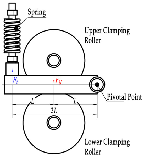
Figure 6.
Schematic of the Floating Adjustment Mechanism.
From the earlier analysis, the required normal pressure applied by the clamping rollers to the cotton stalk is = 1000 N. The functional relationship between the spring force () and this normal pressure () is expressed by the following equation:
Given that the center of gravity of the clamping roller assembly lies on the perpendicular bisector of the moment arm for the spring force, the moment generated by the spring force is twice that generated by the applied pressure. Substituting the relevant parameters into Equation (8) results in a calculated required spring force of = 500 N.
Adequate normal force must be generated by the clamping rollers at the initial engagement phase to successfully feed the cotton stalk into the clamping gap. This is achieved by installing the springs with a preload, designated as , of 20 mm. Previous experimental results determined that the operational spring compression is 4 mm. The functional relationship between spring compression and the resulting spring force is described by Equation (9).
The required spring stiffness, calculated from Equation (9), is k = 20.83 N/mm. In accordance with the Chinese National Standard GB/T 2089-2009 “Dimensions and parameters for cylindrical helical compression springs (ends closed and ground or closed and forged)” [28], a compression spring was selected with the following specifications: a wire diameter of 6 mm, a mean coil diameter of 45 mm, a pitch of 14.2 mm, and a spring rate of 25.55 N/mm.
2.6. Design of the Clamping Roller’s Surface Grooving
The grooved texture on the clamping roller surface is a significant factor influencing the cotton stalk extraction force. These grooves enhance the friction coefficient between the roller surface and the stalk, thereby minimizing slippage during extraction [29]. Furthermore, the grooves promote greater deformation of the rubber material at the clamping interface, which increases the effective contact area with the stalk. The relatively high peripheral speed at the roller–stalk contact point means the groove’s cross-sectional area and depth significantly affect interfacial slippage. Deeper and wider grooves cause the adjacent rubber ridges to compress against each other under load, enhancing the grip on the stalk and reducing slip. Conversely, excessively large groove dimensions reduce the overall structural rigidity of the ridges, making them prone to local buckling and lifting under pressure [30,31,32,33,34,35]. This deformation diminishes the contact area with the stalk, reduces the resulting friction force, and hinders effective stalk extraction. Based on standard grooved patterns used for press rollers, the specific parameters for the clamping roller surface grooving were defined as: a groove depth of 5 mm, a groove width of 17.5 mm, 13 thread starts, a helix angle () of 15°, and a lead of 2345.5 mm. This configuration is illustrated in Figure 7.
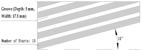
Figure 7.
Design Parameters for the Clamping Roller’s Surface Grooving Pattern.
2.7. Experimental Rig Testing
2.7.1. Experimental Conditions and Methodology
A prototype of the horizontal shaft counter-rolling cotton stalk extraction machine clamping device was manufactured according to the design detailed in the previous sections (Figure 8). Field tests were conducted in Shihezi City, Xinjiang. The test specimens consisted of intact, whole cotton stalks. These stalks were collected from the cotton experimental plots at the Shihezi University Experimental Farm, also located in Shihezi City, Xinjiang, on 11 October 2024. Using a simple random sampling method, 51 cotton stalk plants were selected. The average diameter of the stalk clamping zone was 8.96 mm, with maximum and minimum values of 12.7 mm and 7.34 mm, respectively. The average moisture content of the cotton stalks was 51.9%.
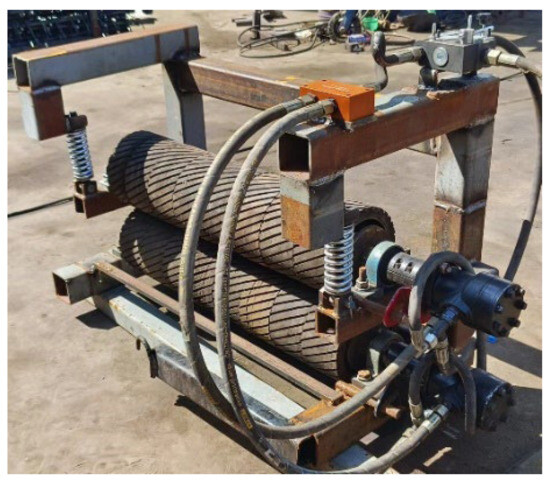
Figure 8.
Clamping Mechanism for Horizontal Shaft Counter-Rolling Cotton Stalk Extraction Machine.
Three experimental factors were selected for investigation: the surface groove pattern of the clamping rollers (), the rotational speed of the clamping rollers (), and the clamping gap width (). The coded levels for these experimental factors are presented in Table 2. Before commencing the tests, a sufficient quantity of whole cotton stalks was prepared. Each experimental treatment combination was replicated three times, and the mean value of these replicates was used as the result for that particular test group.

Table 2.
Experimental Factors and Their Levels.
2.7.2. Evaluation Metrics
Preliminary experimental results characterized the temporal variation in the extraction force exerted on the cotton stalk by the clamping rollers, as depicted in Figure 9. The force profile initiates at 0 N, undergoes a rapid ascent to a maximum peak value, and is followed by a subsequent decline. This decrease is attributed to a reduction in the coefficient of friction at the clamping interface resulting from sustained sliding contact between the roller surface and the stalk. However, under actual field operating conditions, the duration of engagement between the rollers and a single stalk is very short. Consequently, the phase of force degradation due to friction is negligible for practical analysis. The focus of the actual operational analysis is therefore confined to the initial segment of the curve, specifically the rapid force increase from 0 N to the peak value, as illustrated in Figure 9.
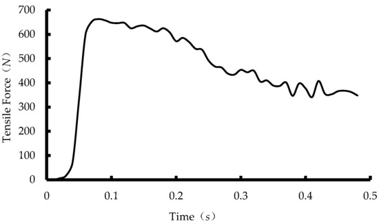
Figure 9.
Time–Variation Plot of Cotton Stalk Extraction Force.
Consequently, this study analyzes the effects of the experimental factors on the extraction force by examining two key characteristics: the absolute magnitude of the peak force and the rapidity of the force increase to that peak. The peak extraction force and the time required to reach this peak force were thus selected as the evaluation indicators for the experiment.
3. Results and Discussion
A three-factor, three-level quadratic regression orthogonal composite experimental design was generated using Design-Expert 13. The corresponding experimental results are presented in Table 3. The data in Table 3 indicate that the maximum observed peak extraction force was 702.8 N.

Table 3.
Box–Behnken Experimental Design and Results.
3.1. Regression Model Development and Analysis of Variance
Multivariate regression analysis was conducted using Design-Expert software. Analysis of variance (ANOVA) for the peak extraction force () and the time to peak force () is presented in Table 4. The ANOVA results show that for both response variables ( and ), the model terms are highly significant (p < 0.01), and the lack-of-fit is not significant (p > 0.05). This indicates that the developed regression models are statistically significant and provide a good fit to the experimental data. Furthermore, the differences between the Predicted and the Adjusted values for both models were less than 0.2, demonstrating that the models are reliable and possess a strong predictive capability (good generalization). Non-significant terms were eliminated from the models based on the statistical analysis. The final reduced regression equations describing the relationship between the three coded factors—roller groove type (), roller speed (), and clamping gap ()—and the responses—peak extraction force () and time to peak force ()—are given by:

Table 4.
Results of the Analysis of Variance.
Multivariate regression analysis was carried out using Design-Expert software. The analysis of variance (ANOVA) for the peak extraction force and the time to peak force is presented in Table 4. The results demonstrate that for the peak extraction force model, the main effects of groove type () and clamping gap (), the two-factor interaction (), and the quadratic effect of groove type () are statistically significant. For the time to peak force model, the main effects of roller speed () and clamping gap (), along with the interaction effects and , were found to be significant. The relative significance of the factors influencing the peak extraction force, in descending order, was: clamping gap width () > roller groove type () > roller rotational speed (). Conversely, the factors affecting the time to peak force, ranked by their significance, were: roller rotational speed () > clamping gap width () > roller groove type (). Notably, the rotational speed of the clamping rollers () did not exhibit a significant effect on the magnitude of the peak extraction force () but was a highly significant factor for the time to peak force (). This can be attributed to the very short duration of the roller–stalk interaction during the extraction event. Within this transient period, variations in rotational speed do not substantially change the interfacial coefficient of friction, hence the negligible impact on the peak force. In contrast, the rate at which the stalk is tensioned is a direct function of the roller’s peripheral speed, making rotational speed a critical determinant of how quickly the peak force is reached. The surface groove type of the clamping rollers () significantly influenced the peak extraction force () but did not have a significant effect on the time to peak force (). The grooved texture enhances the coefficient of friction at the roller–stalk interface, leading to an increase in the maximum force required for extraction. Therefore, groove type is a significant factor for the peak force. However, alterations in the groove pattern do not change the fundamental rotational kinematics (speed) of the rollers. Consequently, the groove type does not significantly alter the time dynamics of the force development, explaining its non-significant effect on the time to peak force.
The relationships between the peak extraction force and its statistically significant factors are illustrated in Figure 10a,b. The peak force demonstrated a distinct non-linear, quadratic relationship with the roller groove type, characterized by an initial increase followed by a decrease. The maximum peak force was achieved when both the upper and lower rollers featured the grooved surface, a condition that maximizes the interfacial coefficient of friction with the stalk. Conversely, the minimum peak force occurred when both rollers were smooth, minimizing the friction coefficient. A mixed configuration (grooved upper roller, smooth lower roller) produced an intermediate friction coefficient and a corresponding peak force value slightly above the all-smooth configuration but significantly below the all-grooved configuration. These results confirm that incorporating a grooved texture on the roller surfaces significantly enhances the extraction force, thereby justifying the earlier design choice of using grooved rollers. A significant negative linear correlation was observed between the peak extraction force and the clamping gap width; the force decreased monotonically as the gap increased. At the smallest gap setting, the rollers made the most intimate contact with the stalk. This promoted greater elastic deformation of the rubber surface, maximized the true contact area, and thus generated the highest peak extraction force. As the gap widened, the contact between the rollers and the stalk became less firm and more intermittent. This reduction in effective contact area directly led to a progressive decline in the achievable peak extraction force.

Figure 10.
Relationships of the Peak Extraction Force and Time to Peak Force with the Experimental Factors. (a): The influence of on . (b): The influence of on . (c): The influence of on . (d): The influence of on .
Figure 10c,d illustrate the relationships between the time to peak force and its significant factors. A significant negative linear correlation was found between the time to peak force and both the roller rotational speed and the clamping gap width. Specifically, the time to peak force increased as the roller speed decreased and as the clamping gap narrowed. An increase in roller rotational speed directly translates to a higher peripheral velocity, which pulls the stalk faster and thus shortens the time required to reach the peak force. A wider clamping gap reduces the intimacy of contact between the roller surfaces and the stalk. This looser engagement minimizes the damping effect (energy loss) on the rollers, allowing them to maintain a speed closer to their set value. The resultant higher effective pulling speed decreases the time to peak force. In contrast, a narrower gap increases contact intimacy and friction, imposing greater damping on the rollers. This damping causes a more significant drop from the set rotational speed, slowing the effective stalk pulling velocity and consequently increasing the time to peak force. These results indicate that achieving a faster stalk extraction speed is facilitated by both higher roller speeds and larger clamping gaps. However, the preceding analysis of peak extraction force demonstrated that a smaller clamping gap is essential for maximizing the extraction force and preventing stalk slippage. This creates a trade-off. Therefore, the final selection of the clamping gap value must be determined through a comprehensive analysis that considers the interaction between these competing effects on both response variables (peak force and time to peak).
3.2. Analysis of Factor Interactions
The analysis of variance (ANOVA) results presented in Table 5 indicate that the two-factor interaction between roller speed () and clamping gap () is significant for the peak extraction force model. For the time to peak force model, the interactions between groove type and roller speed () and between roller speed and clamping gap () are statistically significant. Response surface methodology (RSM) was employed within Design-Expert to analyze these interactions. The resulting response surface plots, which visualize the effect of these interacting factors on the two response variables, are presented in Figure 11.

Table 5.
Results of the Validation Experiments.

Figure 11.
Influence of the Interactions among Various Factors on the Peak Extraction Force and the Time to Peak Force. (a): The influence of
and on . (b): The influence of and on . (c): The influence of and on .
Figure 11a demonstrates that with the roller groove type fixed at its intermediate level and the rotational speed held constant, the peak extraction force exhibits a substantial increase as the clamping gap is reduced. The underlying mechanism is twofold: firstly, a narrower gap induces significant elastic deformation in both the rubber covering the rollers and the stalk material, substantially increasing the effective contact area between them. Secondly, the spring mechanism in the floating adjustment assembly is compressed further at smaller gaps, applying a greater normal clamping force () to the stalk. The synergistic effect of these two conditions—increased contact area and higher normal force—results in a significantly enhanced frictional force, which is the direct cause of the higher observed peak extraction force. When the clamping gap width is maintained at a constant value, the relationship between the peak extraction force and the roller rotational speed reveals two distinct and opposing trends, critically dependent on the gap size: For clamping gaps larger than 2 mm, the peak force decreases with increasing roller speed. Conversely, for gaps smaller than 2 mm, the peak force increases with increasing roller speed. This phenomenon can be explained by the fundamental mechanics of the roller–stalk interaction: Under a small clamping gap, the intimate contact and high compression minimize slippage. A higher rotational speed in this regime applies a very rapid acceleration to the stalk. Newton’s second law dictates that the instantaneous force required to achieve this acceleration is high, leading to a larger peak force reading from the sensor. In contrast, under a large clamping gap, the contact is loose and slippage is inherent. Increasing the roller speed in this high-slip regime exacerbates the relative motion (slippage) between the roller surface and the stalk. This increased slippage reduces the effective coefficient of friction and the force transmission efficiency, ultimately resulting in a lower peak extraction force.
Figure 11b indicates that with the clamping gap fixed at its intermediate level and the groove type held constant, the time to peak force exhibits a highly significant increasing trend as the rotational speed of the clamping rollers decreases. The physical explanation is that the stalk is propelled by the rotating rollers. A higher rotational speed imparts a greater acceleration to the stalk, which in turn reduces the time required for the tension force measured by the load cell to ramp up to its maximum value. When the rotational speed is maintained at a constant value, the effect of groove type on the time to peak force is more subdued and reveals two contrasting patterns depending on the speed level: At high rotational speeds, where speed is the dominant factor governing the time to peak force, the grooved texture increases the interfacial friction. This elevated friction imposes a higher torque load on the hydraulic motors driving the rollers. If the motor’s power output is limited, this increased load can cause a slight decrease in the actual operational speed (a load-induced speed drop). This reduction in effective pulling speed slows the stalk’s acceleration, ultimately increasing the time taken to reach the peak force. At lower rotational speeds, the primary role of the grooves is to increase the coefficient of friction at the roller–stalk interface. This enhanced grip significantly suppresses slippage between the two surfaces. By minimizing energy-wasting slip, the grooves ensure that a greater proportion of the roller’s rotational motion is converted into translational motion of the stalk. This maintains a higher effective acceleration for the stalk under these low-speed conditions, leading to a shorter time to reach the peak force.
Figure 11c shows that with the groove type set to its intermediate level, the time to peak force increases with decreasing values of both roller rotational speed and clamping gap width. The sensitivity of the time to peak force to changes in the clamping gap is particularly pronounced at lower rotational speeds. The underlying mechanism is that a narrower clamping gap intensifies the compressive interaction between the rollers and the stalk. This causes greater elastic deformation in the rubber surface and the stalk itself, and increases the compression of the adjustment mechanism’s springs. These effects collectively impose a significantly higher torque demand on the drive motors to maintain rotation. Under a constant power input, this increased load can cause a measurable decrease in the actual rotational speed of the rollers. This load-induced speed reduction lowers the rate at which the stalk is pulled, thereby increasing the time required to reach the peak force. At high rotational speeds, the roller speed becomes the dominant factor controlling the time to peak force. The high peripheral velocity ensures a rapid stalk acceleration phase, leading to a short time to peak force. Under these conditions, the effect of varying the clamping gap on the final time to peak force value is secondary and becomes less noticeable; the peak time remains comparatively low across the range of gap widths tested.
3.3. Parameter Optimization and Validation Experiments
Numerical optimization was performed on the developed models using the Design-Expert software. The optimization criteria were defined as maximizing the peak extraction force () and minimizing the time to peak force (). The formal objective function and the associated constraints for this multi-response optimization are specified in Equation (12):
The numerical optimization procedure converged on the optimal parameter combination: a grooved surface texture for both the upper and lower clamping rollers, a rotational speed of 220 rpm, and a clamping gap of 0 mm. The model predicts a theoretical peak extraction force () of 702.80 N and a theoretical time to peak force () of 0.048 s for this combination. This predicted peak force fulfills the design criterion of being below the ultimate tensile strength of compressed stalks (994.60 N) to prevent breakage, while also being substantially higher than the measured stalk extraction resistance to ensure successful uprooting. An experimental validation was conducted using the optimized parameters (both rollers grooved, 220 rpm, 0 mm gap) under controlled conditions on the test stand. Five replicate trials were performed to ensure statistical reliability, and the average results are presented in Table 5. The experimental mean peak extraction force was 710.77 N, and the mean time to peak force was 0.05 s. These empirical results show excellent agreement with the model’s predictions (702.80 N, 0.048 s), confirming the high reliability and predictive accuracy of the developed regression models and the optimization methodology. This validates the use of this model-based approach for the structural optimization of the clamping mechanism in horizontal shaft counter-rolling cotton stalk extraction machines.
4. Conclusions
- 1.
- Addressing the problem of high stalk breakage rates associated with current horizontal shaft counter-rolling whole-stalk cotton stalk extraction machines, the tensile properties of stalks following rapid compression were investigated by simulating the extraction forces using a universal testing machine. This study established a conservative lower limit for the post-compression tensile strength of 17.93 MPa, corresponding to an ultimate tensile force of 994.60 N, which served as a critical design constraint to prevent stalk fracture. Leveraging the findings on the post-compression tensile behavior of cotton stalks, the design incorporated the Euler-Eytelwein formula from belt friction theory alongside relevant geometric relationships. This analytical foundation was used to determine key design parameters: a clamping roller radius of 100 mm, an operational speed range of 96 to 268 rpm, a working width of 800 mm to match the common planting pattern, and a spring stiffness of 25.55 N/mm for the floating adjustment mechanism.
- 2.
- The primary factors influencing the peak extraction force () and the time to peak force () were identified through a foundational study on the post-compression tensile characteristics of cotton stalks and a subsequent mechanics analysis of the roller–stalk interaction. A Response Surface Methodology (RSM) experimental design was implemented to investigate these factors. Analysis of Variance (ANOVA) of the results revealed that the significance of factors on the peak extraction force, ranked in descending order, was: clamping gap width () > roller groove type () > roller rotational speed (). For the time to peak force, the order of significance was: roller rotational speed () > clamping gap width () > roller groove type (). Numerical optimization was conducted to determine the optimal parameter set. Experimental validation using this optimal combination—specifically, grooved surfaces on both rollers, a rotational speed of 220 rpm, and a clamping gap of 0 mm—yielded a mean peak extraction force of 710.77 N and a mean time to peak force of 0.05 s. The relative errors between these empirical results and the model’s predictions (702.80 N, 0.048 s) were 1.12% for the force and 4.00% for the time, both well within the acceptable 5% threshold. This close agreement confirms the accuracy and predictive capability of the developed models. The measured peak force (710.77 N) under optimal parameters remained substantially below the ultimate tensile strength of the compressed stalk (994.60 N), ensuring stalk integrity and preventing breakage. Simultaneously, the short time to peak force (0.05 s) indicated a rapid extraction process.
- 3.
- The results demonstrate that the designed clamping device for the horizontal shaft counter-rolling cotton stalk extraction machine achieves a high extraction speed while preventing stalk breakage. The findings provide a theoretical basis and design reference for the development of such extraction machines. This study focuses on investigating the influence of the clamping device’s operational parameters on the extraction force and speed, with particular emphasis on the interaction between the clamping rollers and the cotton stalks. Consequently, a limitation of this research is that it does not account for factors such as root–soil interaction forces, soil moisture content, or residual film entanglement around the roots, which may affect stalk extraction. Furthermore, this study optimized the clamping device to address the limitations of existing horizontal shaft counter-rolling cotton stalk pullers. While both power requirements and costs meet practical operational demands, the hydraulic drive system may experience fluctuations during actual operation due to instantaneous load variations, which could affect the rotational speed and torque of the hydraulic motors. In summary, future work should further optimize the operational parameters of the clamping device by incorporating practical field conditions and other relevant factors.
Author Contributions
Conceptualization, J.Z.; methodology, J.L. and J.G.; validation, H.W.; formal analysis, J.Z., H.W.; data curation, J.Z., H.W.; investigation, J.Z., H.W. and H.S.; writing—original draft preparation, J.Z. and H.W.; writing—review and editing, J.L., J.G. and Z.Z.; supervision, J.L., J.G. and Z.Z. All authors have read and agreed to the published version of the manuscript.
Funding
This work was funded by Xinjiang Uygur Autonomous Region High-end Intelligent Agricultural Machinery Industry Innovation Research Institute Project (NO. FZ0011), and Research Initiation Program for High-level Talents of Shihezi University (NO. RCZK202311).
Institutional Review Board Statement
Not applicable.
Data Availability Statement
Data are contained within the article.
Conflicts of Interest
The authors declare no conflicts of interest.
References
- National Bureau of Statistics. Announcement of the National Bureau of Statistics on Cotton Production in 2024 [EB/OL]. Available online: https://www.stats.gov.cn/sj/zxfb/202412/t20241225_1957879.html (accessed on 25 December 2024).
- Ashutosh, P.P.; Abhijit, K.; Mehta, C.R.; Gautam, M.; Ramkrushna, I.; Vellaichamy, M.; Abhay, O.S. Technological Advancement in Harvesting of Cotton Stalks to Establish Sustainable Raw Material Supply Chain for Industrial Applications: A Review. Trans. Chin. Soc. Agric. Mach. 2023, 16, 741–760. [Google Scholar] [CrossRef]
- Holt, G.A.; Chow, P.; Wanjura, J.D.; Pelletier, M.G.; Wedegaertner, T.C. Evaluation of thermal treatments to improve physical and mechanical properties of bio-composites made from cotton byproducts and other agricultural fibers. Ind. Crops Prod. 2014, 52, 627–632. [Google Scholar] [CrossRef]
- Venkatesan, A.; Srividhya, B.; Abdalrahman, A.; Abdellatif, M.S.; Rama, K.C.; Mohamed, A.H.; Senthil, K.; Guganathan, L.; Ragupathy, S. High adsorption capacities of rhodamine B dye by activated carbon synthesized from cotton stalks agricultural waste by chemical activation. Ceram. Int. 2025, 51, 13345–13354. [Google Scholar] [CrossRef]
- Narendra, R.; Yang, Y.Q. Properties and potential applications of natural cellulose fibers from the bark of cotton stalks. Bioresour. Technol. Sci. 2009, 100, 3563–3569. [Google Scholar] [CrossRef]
- Shen, C.; Guo, H.; Dai, Y.M.; Li, F.; Cao, S.L.; Jin, X.W.; Shen, L.; Deng, Y. Current Status and Development Strategies of Cotton Stalk Recycling Mechanization in Xinjiang. J. Huazhong Agric. Univ. 2023, 42, 53–63. [Google Scholar] [CrossRef]
- Cai, C.G.; Wang, Z.B.; Ma, L.; Xu, Z.X.; Yu, J.M.; Li, F.G. Cotton stalk valorization towards bio-based materials, chemicals, and biofuels: A review. Renew. Sustain. Energy Rev. 2024, 202, 114651. [Google Scholar] [CrossRef]
- He, R.Y.; Duan, Q.F.; Chen, X.X.; Xu, G.M.; Ding, Q.S. Discrete element analysis of straw spatial distribution quality in rotary tillage and straw incorporation. Trans. Chin. Soc. Agric. Mach. 2022, 53, 44–53. [Google Scholar] [CrossRef]
- Li, Y.; Zhang, Q. Effects of naturally and microbially decomposed cotton stalks on cotton seedling growth. Arch. Agron. Soil Sci. 2016, 62, 1264–1270. [Google Scholar] [CrossRef]
- Chen, J.C.; Qu, Q.; Lu, J.Z.; Wang, H.Q.; Gu, F.; Zhu, M.Q. The structural characteristics and pyrolysis products properties based on cotton stalks and husks. Ind. Crops Prod. 2025, 227, 120858. [Google Scholar] [CrossRef]
- Ma, Y.Y. Effects of Cotton Stalk Biochar on Cotton Verticillium Wilt and Cotton Growth; Northwest A&F University: Yangling, China, 2014. [Google Scholar]
- Sumner, H.R.; Monroe, G.E.; Hellwig, R.E. Design Elements of a Cotton Plant Puller. Trans. ASAE 1984, 27, 366–369. [Google Scholar] [CrossRef]
- Alamgir, A.K.; Umair, S.; Ramesh, P.R.; Ehsan, F.; Kashif, M.; Khan, M.M.; Hashim, S.; Zohaib, M.; Ahmad, S.I. Structural analysis of cotton stalk Puller and Shredder Machine. Alex. Eng. J. 2023, 64, 335–347. [Google Scholar] [CrossRef]
- Ramadan, Y.Y.R. Development and evaluation of a cotton stalk puller. J. Soil Sci. Agric. Eng. 2010, 1, 1061–1073. [Google Scholar] [CrossRef]
- Wang, Z.; Zhao, W.; Fu, J.; Xie, H.; Zhang, Y.; Chen, M. V-Shaped Toothed Roller Cotton Stalk Puller: Numerical Modeling and Field-Test Validation. Agriculture 2023, 13, 1157. [Google Scholar] [CrossRef]
- Cai, J.L.; Zhang, J.X.; Guo, G.; Gao, Z.B.; Wang, X.X. Improved design and test of flexible cotton stalks puller. Int. J. Agric. Biol. Eng. 2023, 16, 78–84. [Google Scholar] [CrossRef]
- Wang, Y.; Zhang, J.; Shen, S.; Li, J.; Huo, Y.; Wang, Z. The Mechanical Analysis and Comparative Performance Test of the Roller-Type Pulling Mechanism for the Whole Cotton Stalk Pulling Machine. Agriculture 2024, 14, 506. [Google Scholar] [CrossRef]
- Ablikem, A.; Yasenjiang, B.; Song, L.; Maheimuti, A. Design of a Coaxial Counter-Rotating Rubber Roller Cotton Stalk Pulling Device. Agric. Sci. Technol. Equip. 2023, 5, 31–36. [Google Scholar] [CrossRef]
- Chen, M.J. Research on Key Technologies of Disc-Tooth Cotton Stalk Removal Machinery; Chinese Academy of Agricultural Sciences: Beijing, China, 2022. [Google Scholar] [CrossRef]
- He, X.W.; Liu, J.X.; Xu, Y.; Wang, L.; Gao, X.J.; Wang, X.F. Improved Design of a 4MB-6 Dense Planting Cotton Stalk Row-Aligned Shovel-Pulling and Laying Machine. Trans. Chin. Soc. Agric. Mach. 2020, 51, 21–30. [Google Scholar] [CrossRef]
- Buerlan, K.; Wang, J.K.; Luo, X.Y.; Luo, Y.J.; Wang, Z. Design and Experiment of a Horizontal Roller-Type Cotton Stalk Pulling and Harvesting Machine. J. Agric. Mech. Res. 2020, 42, 128–133. [Google Scholar] [CrossRef]
- GB/T 1939-2009; Test Method for Transverse Compression of Wood. China Standards Press: Beijing, China, 2009.
- GB/T 1938-2009; Test Method for Tensile Strength Parallel to Grain of Wood. China Standards Press: Beijing, China, 2009.
- Zhao, W.S.; Xie, J.H.; Chen, M.J.; Gao, Q.M.; Cao, S.L.; Wang, Z.W.; Chen, Y.S. Design and experiments of the clamping and uprooting device with adjustable stiffness for a cotton stalk. Trans. Chin. Soc. Agric. Eng. 2024, 40, 35–45. [Google Scholar] [CrossRef]
- Jin, C.Q.; Qi, Y.D.; Liu, G.W.; Yang, T.X.; Ni, Y.L. Mechanism analysis and parameter optimization of soybean combine harvester reel. Trans. Chin. Soc. Agric. Mach. 2023, 56, 104–113. [Google Scholar] [CrossRef]
- Wang, Y.; Zhang, J.; Huo, Y.; Wang, Z.; Li, J.; Li, Z. Comparison and Experimental Study of Cotton Stalk Extraction via Nip Roller Based on Nip Motion Trajectory Equation. Agriculture 2024, 14, 950. [Google Scholar] [CrossRef]
- Chinese Academy of Agricultural Mechanization Sciences. Agricultural Machinery Design Manual; China Agricultural Science and Technology Press: Beijing, China, 2007; pp. 903–904. [Google Scholar]
- GB/T 2089-2009; Dimensions and Parameters for Cylindrical Helical Compression Springs (Ends Closed and Ground or Closed and Forged). China Standards Press: Beijing, China, 2009.
- Yang, Z.K.; Zhang, K.P.; Yang, J.L.; Yao, Y.P. Parameter Optimization and Experimental Study on Alfalfa Stem Flattening Process Based on DEM–MBD. Agriculture 2025, 15, 922. [Google Scholar] [CrossRef]
- Xu, S.Y.; Chen, Y.X.; Lin, C.; Liu, S.H. Design and Experiment of a Banana Stem Roller-Type Pressing Dehydrator. Trans. Chin. Soc. Agric. Eng. 2024, 40, 21–32. [Google Scholar] [CrossRef]
- Li, F.Z.; Ma, X.J.; Liu, J.; Wang, A.; Wang, D.H. Influence of Tread Groove Depth on Tire Performance. Tire Ind. 2023, 43, 195–198. [Google Scholar] [CrossRef]
- Zhang, Z.Y.; Deng, W.W.; Hua, C.Y.; Cheng, Y.Z.; Ye, B.Y.; An, C.W.; Wang, J.Y.; Li, X.D. Simulation Study on Plasticizing Process of Modified Double-Base Propellant by Groove Calendering. Propellants Explos. Pyrotech. 2025, 50, 12054. [Google Scholar] [CrossRef]
- Gao, Z.B.; Jiang, H.M.; Liu, Z.H.; Chen, S.J. Influence of Tire Tread Pitch on Low-Frequency Noise. Mach. Des. Manuf. 2022, 9, 5–8. [Google Scholar] [CrossRef]
- Liu, X.Y.; Cao, Q.Q.; Zhu, C.Z.; Huang, X.M.; Lin, M. Numerical Simulation of Critical Hydroplaning Speed for Tires on Asphalt Concrete Pavement. J. Southeast Univ. (Nat. Sci. Ed.) 2017, 47, 1020–1025. [Google Scholar] [CrossRef]
- Kuraishi, T.; Takizawa, K.; Tezduyar, T.E. Tire aerodynamics with actual tire geometry, road contact and tire deformation. Comput. Mech. 2019, 63, 1165–1185. [Google Scholar] [CrossRef]
Disclaimer/Publisher’s Note: The statements, opinions and data contained in all publications are solely those of the individual author(s) and contributor(s) and not of MDPI and/or the editor(s). MDPI and/or the editor(s) disclaim responsibility for any injury to people or property resulting from any ideas, methods, instructions or products referred to in the content. |
© 2025 by the authors. Licensee MDPI, Basel, Switzerland. This article is an open access article distributed under the terms and conditions of the Creative Commons Attribution (CC BY) license (https://creativecommons.org/licenses/by/4.0/).