Article

Research on the Design of an Omnidirectional Leveling System and Adaptive Sliding Mode Control for Tracked Agricultural Chassis in Hilly and Mountainous Terrain

1
Automotive Engineering Research Institute, Jiangsu University, Zhenjiang 212013, China
2
Faculty of Agricultural Engineering, Jiangsu University, Zhenjiang 212013, China
3
School of Automotive and Traffic Engineering, Jiangsu University, Zhenjiang 212013, China
4
Jiangsu Chaoli Electric Manufacture Co., Ltd., Zhenjiang 212013, China
*
Author to whom correspondence should be addressed.
Agriculture 2025, 15(18), 1920; https://doi.org/10.3390/agriculture15181920
Submission received: 3 August 2025 / Revised: 29 August 2025 / Accepted: 9 September 2025 / Published: 10 September 2025
(This article belongs to the Section Agricultural Technology)

Abstract

To address the suboptimal leveling performance and insufficient slope stability of existing agricultural machinery chassis in hilly and mountainous regions, this study proposes an innovative omnidirectional leveling system based on a “double-layer frame” crawler-type agricultural chassis. The system employs servo-electric cylinders as its actuation components. A control model for the servo-electric cylinders has been established, accompanied by the design of an adaptive sliding mode controller (ASMC). A co-simulation platform was developed utilizing Matlab/Simulink and Adams to evaluate system performance. Comparative simulations were conducted between the ASMC and a conventional PID controller, followed by comprehensive machine testing. Experimental results demonstrate that the proposed double-layer frame crawler chassis achieves longitudinal leveling adjustments of up to 25° and lateral adjustments of 20°. Through structural optimization and the application of ASMC (in contrast to PID), both longitudinal and lateral leveling response times were reduced by 1.12 s and 0.95 s, respectively. Furthermore, leveling velocities increased by a factor of 1.5 in the longitudinal direction and by a factor of 1.3 in the lateral direction, while longitudinal and lateral angular accelerations decreased by 15.8% and 17.1%, respectively. Field tests confirm the system’s capability for adaptive leveling on inclined terrain, thereby validating the enhanced performance of the proposed omnidirectional leveling system.

1. Introduction

China features extensive hilly and mountainous regions [1,2] where cultivated land is often fragmented, dispersed [3], and characterized by significant slope variations and complex topography [4,5]. Conventional agricultural machinery chassis typically lack automatic leveling capabilities, which compromises operational stability [6], reduces mobility, diminishes efficiency, and introduces potential safety risks [7,8]. These limitations considerably impede the progress of agricultural mechanization in such terrains [9,10]. Consequently, the development of innovative agricultural machinery chassis with integrated frame leveling functionality is crucial for promoting the mechanization of agriculture in hilly and mountainous areas [11,12,13].
The leveling chassis system mainly consists of a sensor network, actuating components, and an intelligent control module [14,15]. By facilitating real-time perception and dynamic adjustment of vehicle posture, this system effectively mitigates the decline in operational performance caused by uneven terrain and steep slopes [16,17,18]. It significantly enhances the operational stability and efficiency of machinery engaged in harvesting, crop protection, and orchard operations within complex terrains such as hilly regions, mountainous areas, and orchards [19,20,21]. Sun et al. [22] proposed an omnidirectional leveling method for a hydraulic four-point lifting chassis. Their cooperative control strategy utilizing four cylinders effectively reduces the risk of rollover associated with center-of-gravity offset. Wang et al. [23] designed an omnidirectional automatic leveling system that incorporates a “three-layer articulated frame” aimed at tracked machinery operating on steep slopes to mitigate overturning risks. This system enables comprehensive posture adjustments under pitch, roll, and combined inclination conditions, thereby significantly enhancing operational safety and stability. Chai et al. [24] investigated the interaction mechanisms and dynamic stress response characteristics between tracked chassis and complex terrain, considering various height adjustments, lateral and longitudinal leveling angles, as well as ridge-crossing methods. This research addresses reliability concerns in posture-adjusting combine harvesters and provides a theoretical foundation for enhancing chassis structural stability. Hu et al. [25] designed a four-point lifting adjustable chassis along with an adaptive leveling system aimed at mitigating body tilting of tracked agricultural machinery operating on rugged terrain. By integrating posture detection with hydraulic drive cooperative control, the system facilitates precise adjustments of height, roll, and pitch, thereby significantly improving operational stability on complex terrains. Tan et al. [26] proposed a dual-degree-of-freedom dynamic balance control scheme that integrates lateral and longitudinal hydraulic leveling modules to achieve omnidirectional posture compensation under combined inclinations across all four quadrants. Sun et al. [27] developed an omnidirectional leveling mountain-tracked unmanned tractor that utilizes a “parallelogram mechanism” alongside a “double-frame structure.” This design enables full-body omnidirectional leveling, substantially enhancing slope operation stability and safety. Dettù et al. [28] addressed the leveling requirements of combine harvesters traversing high-inclination terrain through a dual-layer cascaded control approach based on a grey-box model, which achieved stable cooperative control of roll and pitch angles. Jiang et al. [29] introduced a composite control method that integrates Q-learning reinforcement learning, backpropagation (BP) neural networks, and proportional-integral-derivative (PID) control. This approach enabled online optimization of neural network weights and real-time tuning of controller parameters. Experimental results demonstrated that the lateral leveling time (20°) was reduced to 2.8 s, while the longitudinal leveling time (25°) decreased to 3.2 s, both without overshooting. Additionally, body inclination was stabilized within ±1.5° during dynamic and static tests, thereby significantly enhancing operational safety and quality on slopes. Yang et al. [30] developed a kinematic model for vehicles equipped with implements for contour farming operations in mountainous regions. They proposed a cooperative posture control system combining PID leveling for the chassis with dual-loop fuzzy PID profiling for the implement itself. The simulation results indicated that lateral inclination errors were confined within 1.90° for the chassis and 0.93° for the implement, effectively meeting precision and stability requirements necessary for hilly slope operations. Zhao et al. [31] presented an adaptive dual-loop composite leveling system based on active suspension technology, which was optimized using an enhanced adaptive genetic algorithm. This innovation considerably improved the leveling performance of agricultural chassis across various road conditions. Peng et al. [32] developed a sliding-mode variable structure control algorithm featuring fuzzy switch gain regulation for a four-point leveling mechanism. This approach successfully achieved real-time dynamic automatic leveling control, significantly enhancing overall precision and stability. In summary, contemporary agricultural leveling chassis systems primarily utilize multi-point hydraulic actuators, such as three- or four-point support configurations, in conjunction with kinematic decoupling mechanisms like parallel linkages or multi-link systems. However, these systems are often constrained by structural complexity, high inertial mass, maintenance challenges, and inherent nonlinear hysteresis associated with hydraulic components, all of which negatively impact their response speed and operational reliability under dynamic conditions. From a control perspective, existing research has largely employed PID-based controllers and their intelligent extensions, such as fuzzy PID and neural network-based tuning methods, which have demonstrated some improvements in disturbance rejection. Nevertheless, under challenging terrain conditions commonly found in hilly and mountainous regions, current leveling systems still face significant limitations in terms of response time—often exceeding three seconds—and leveling range, typically less than 20° longitudinally and 15° laterally. These limitations compromise their ability to provide stable support on steep slopes. Considering the undulating and frequently varying terrain characteristics prevalent in China’s hilly and mountainous regions, there is an urgent need for leveling mechanisms capable of accommodating a broader range of motion to ensure both operational safety and equipment functionality on steep inclines. Consequently, achieving large-angle leveling performance—specifically 25° longitudinally and 20° laterally—along with a control framework and mechanical design that offer faster response, enhanced robustness, and improved adaptability, has become a crucial and challenging research objective.
To overcome these performance limitations, this paper introduces a dual-frame omnidirectional leveling system for agricultural chassis based on Adaptive Sliding Mode Control (ASMC). The system utilizes servo-electric cylinders as the primary actuators, aiming to enable rapid and precise leveling under steep slope conditions (25° longitudinal and 20° lateral), thereby significantly improving the chassis’ responsiveness and posture stability on rugged terrain. A high-precision control model of the servo-electric cylinder is developed, and an adaptive sliding mode controller is designed accordingly. To validate the proposed approach, a co-simulation platform based on Matlab/Simulink and Adams was established. Comprehensive simulations and full-scale experimental tests were conducted with classical PID control serving as a baseline. The results indicate that the proposed dual-frame chassis not only reliably accomplishes the targeted large-angle leveling tasks but also effectively maintains a horizontal posture under slope conditions, surpassing the performance of conventional control methods. This outcome confirms the effectiveness of the system architecture and the superiority of the proposed control algorithm.

2. Design of an Omnidirectional Leveling System for Crawler-Type Agricultural Chassis

2.1. Design Requirements and Proposed Solutions

The complex operational environments in hilly and mountainous areas, characterized by fragmented plots, narrow field passages, and dense curves, impose stringent requirements on the trafficability, maneuverability, and slope stability of agricultural equipment. Existing leveling chassis technologies still suffer from multiple adaptability limitations: poor trafficability and excessive turning radius [33]; imbalance between lightweight design and load capacity, leading to soil compaction due to high ground pressure [34]; and difficulty in balancing travel speed with both safety and efficiency, thereby constraining overall operational performance [35].
To address these challenges, the designed omnidirectional leveling system for tracked agricultural chassis must feature compact dimensions, a small turning radius, strong trafficability, and high operational reliability. Furthermore, it should support multiple functional applications—including spraying, transplanting, transportation, mowing, and irrigation—while maintaining full-machine balance during operation. In accordance with the research context of this study, the proposed omnidirectional leveling system for tracked agricultural chassis is required to meet the following two aspects of specifications:
(1) The chassis dimensions shall not exceed 1.8 m × 1.2 m × 1.2 m (L × W × H), with a total machine mass not exceeding 800 kg, it should attain a maximum travel speed of at least 3 m/s; maintain a minimum turning radius of no more than 3 m; and have a load capacity of at least 200 kg.
(2) The system must uphold a horizontal vehicle posture in all orientations—encompassing both longitudinal and lateral directions—without experiencing rollover during operation on maximum longitudinal slopes of up to 25° and lateral slopes of up to 20°.
To fulfill these specifications, a new omnidirectional leveling system for tracked agricultural chassis has been developed as illustrated in Figure 1 This system comprises a body frame, intermediate frame, chassis frame, upper and lower supports, along with four leveling servo-electric cylinders. These cylinders are interconnected via hinge joints between the body frame and chassis frame which facilitates controlled cylinder extension and retraction for effective longitudinal and lateral slope leveling. By integrating a hinged point-line composite support structure combined with a double-layer leveling configuration, this design effectively addresses the “leg vacancy” phenomenon frequently observed in multi-point support systems during dynamic leveling operations [36,37]. Notably, lateral and longitudinal leveling functions remain decoupled which ensures independent control while enhancing overall system performance.

2.2. Structural Stability Analysis

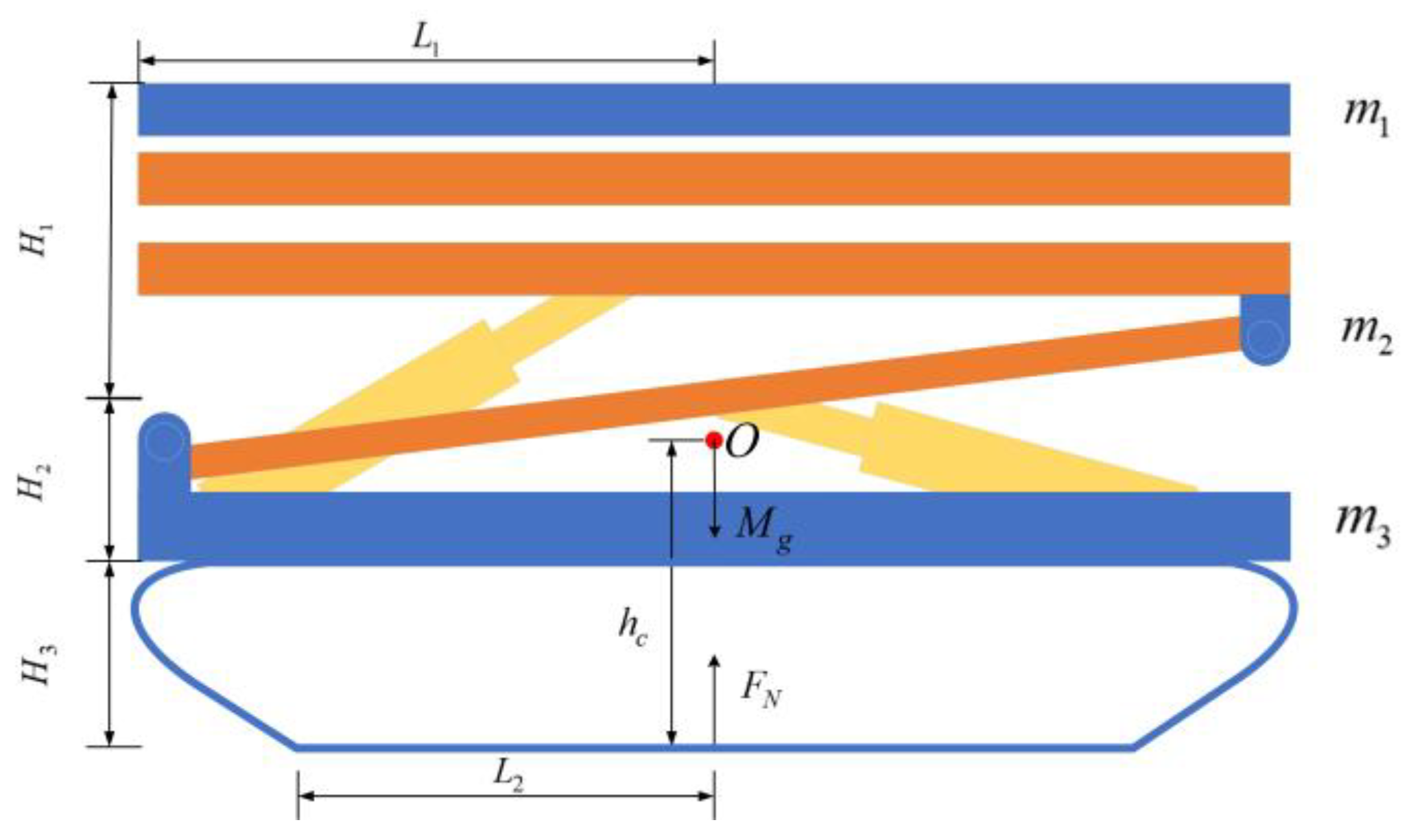
To ensure the operational stability of tracked agricultural machinery chassis on complex terrain in hilly and mountainous regions, this study develops mathematical models through appropriate simplifications of the chassis structure. The longitudinal and lateral rollover angles are calculated, and their variations under heavy-load operating conditions are analyzed in order to evaluate whether the designed omnidirectional leveling system satisfies the overall design requirements. The mathematical model of the tracked agricultural chassis under static horizontal loading is illustrated in Figure 2.
In the figure, m 1 denotes the mass of the upper frame ( m 1 = 250   k g ), while m 2 represents the mass of the intermediate frame ( m 2 = 250   k g ). The total mass of the chassis assembly (including the lower frame) is defined as m 3 ( m 3 = 300   k g ). The vertical separation between the upper and intermediate frames is designated H 1 ( H 1 = 0.5   m ), and H 2 indicates the height difference between the intermediate frame and the bottom frame ( H 2 = 0.3   m ). H 3 corresponds to the overall chassis height ( H 3 = 0.4   m ). The parameter h c quantifies the vertical distance from the system’s center of mass to the slope surface. Geometrically, L 1 specifies the distance from the uppermost point of the upper frame to the central axis ( L 1 = 0.9   m ), and L 2 defines the distance from the top plane of the chassis to this same central axis ( L 2 = 0.6   m ). For mechanical equilibrium analysis, F N signifies the ground support reaction force, and M g represents the full-machine gravitational force.

2.2.1. Calculation of the Center of Gravity Position

The position of the center of mass is pivotal in determining the stability of tracked agricultural machinery chassis [38,39,40]. Under conditions involving static horizontal loading, static slope loading, and leveling operations, variations in equipment posture and configuration result in alterations to the spatial location of the center of mass. This change directly affects the distance between the projection point of the support polygon and the rollover axis, thereby influencing the overall stability of the machinery. Consequently, it is essential to calculate the position of the center of mass under these three operational scenarios for an accurate assessment of chassis stability.
This study employs analytical computation to determine the center of mass for the tracked agricultural machinery. As illustrated in Figure 2, the center-of-mass offset Δ X c (indicating the displacement of the center of mass before and after the leveling process) and its vertical distance to the slope surface h c under static loading can be mathematically expressed as:
Δ X c = 0
h c = m 1 H 1 + H 2 + H 3 + m 2 H 2 + H 3 + m 3 H 3 m 1 + m 2 + m 3
During longitudinal slope leveling of the tracked agricultural chassis, wherein the front servo-electric cylinder functions as the active actuator, the center-of-mass offset Δ X c z 1 (The center of mass before to leveling is denoted as point O, and after the leveling process, it is represented as point O′. The positional displacement between these two points is indicated by Δ X c z 1 .) and the vertical distance to the slope surface h c z 1 are defined as follows. In contrast, lateral leveling entails only variations in the upper frame (i.e., changes in H 1 ), Δ X c z 1 and h c z 1 correspondingly represent the center-of-mass offset and the vertical distance to the slope surface during lateral leveling operations.
Δ X c z 1 = m 1 L ( 1 cos θ ) m 1 + m 2 + m 3
h c z 1 = m 1 H 1 sin θ + H 2 + H 3 + m 2 H 2 + H 3 + m 3 H 3 m 1 + m 2 + m 3
During the process of longitudinal slope leveling, with the rear servo-electric cylinder functioning as the active cylinder, we define the center-of-mass offset Δ X c z 2 (The center of mass before to longitudinal leveling is denoted as point O, and after the leveling process, it is represented as point O′. The positional displacement between these two points is indicated by Δ X c z 2 .) and the vertical distance to the slope surface h c z 2 are defined as follows:
Δ X c z 2 = m 1 + m 2 L 1 ( 1 cos θ ) m 1 + m 2 + m 3
h c z 2 = m 1 H 1 sin θ + H 2 sin θ + H 3 + m 2 H 2 sin θ + H 3 + m 3 H 3 m 1 + m 2 + m 3

2.2.2. Longitudinal Stability Analysis

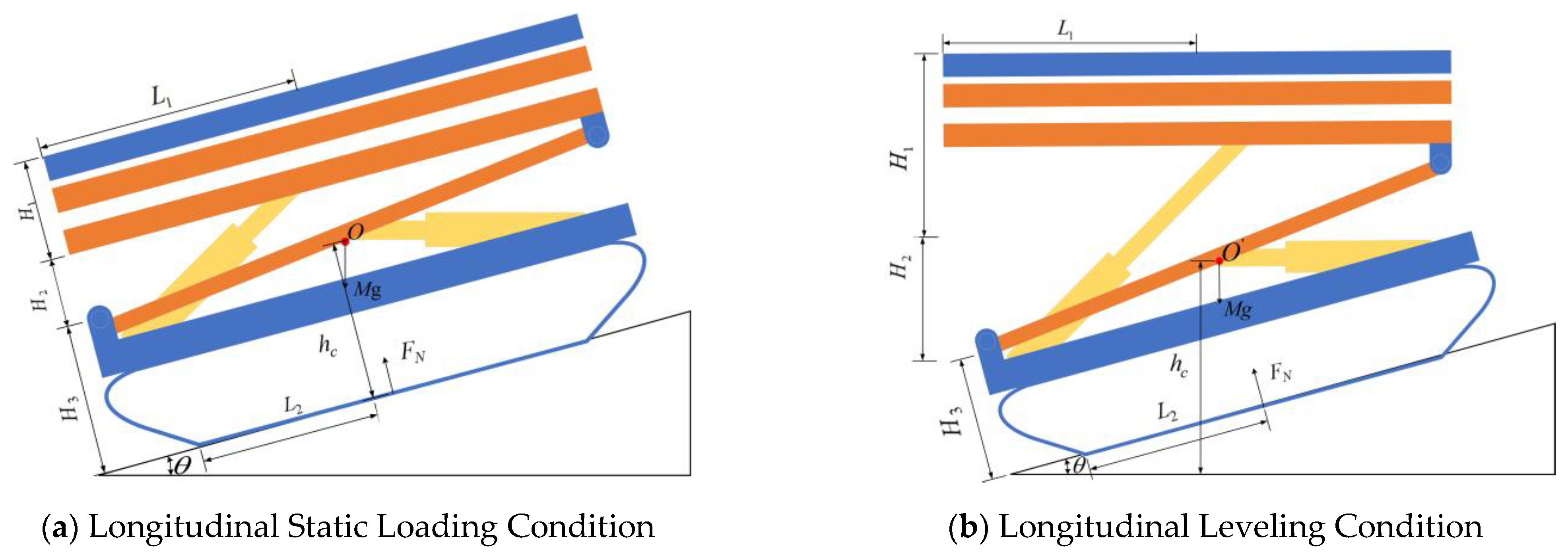
During longitudinal slope traversal in hilly and mountainous terrain, variations in incline due to topographic undulations heighten the risk of chassis rollover for agricultural machinery. To analyze longitudinal slope stability, a comprehensive mathematical model for full-machine longitudinal rollover was developed, as depicted in Figure 3, allowing for the calculation of the longitudinal rollover angle.
The distance X from the support force to the end of the track under static longitudinal loading is derived from the moment equilibrium equation (Equation (7)), as articulated in Equation (8):
M g h c sin θ M g L 2 cos θ + F N X = 0
X = M g ( L 2 cos θ h c sin θ ) F N
In order to prevent a complete machine rollover, the condition X 0 must be satisfied. When X = 0 which signifies that the full gravitational force Mg of machine at the end point of the track-the system attains its rollover threshold. The limiting rollover angle θ is given by Equation (9):
θ = arctan L 2 m 1 + m 2 + m 3 m 1 H 1 + H 2 + H 3 + m 2 H 2 + H 3 + m 3 H 3
In a similar vein, the longitudinal rollover angles during leveling operations are derived from the moment equilibrium equations (Equations (10) and (12)), as illustrated in Equations (11) and (13), respectively. Specifically, Equation (11) pertains to the longitudinal rollover angle when the front servo-electric cylinder is working, while Equation (13) corresponds to the longitudinal rollover angle where the rear servo-electric cylinder is working.
M g h c z 1 sin θ M g cos θ L 2 + Δ X c z 1 + F N L 2 = 0
θ = arctan L 2 + Δ X c z 1 h c z 1 = arctan L 2 m 1 + m 2 + m 3 + m 1 L 1 ( 1 cos θ ) m 1 H 1 sin θ + H 2 + H 3 + m 2 H 2 + H 3 + m 3 H 3
M g h c z 2 sin θ M g cos θ L 2 + Δ X c z 2 + F N L 2 = 0
θ = arctan L 2 + Δ X c z 2 h c z 2 = arctan L 2 m 1 + m 2 + m 3 + m 1 + m 2 L 1 ( 1 cos θ ) m 1 H 1 sin θ + H 2 sin θ + H 3 + m 2 H 2 sin θ + H 3 + m 3 H 3
The longitudinal rollover angles for the tracked agricultural chassis, evaluated under both non-leveling and leveling conditions using Equations (9), (11) and (13), are presented in Table 1. The findings confirm compliance with the design specifications-specifically, no rollover is encountered at the maximum longitudinal slope of 25°. Furthermore, the analysis demonstrates a significant increase in the threshold for rollover angles when leveling conditions are applied. This enhancement facilitates an expansion of the operational limits of the chassis regarding maximum longitudinal slope.

2.2.3. Lateral Stability Analysis

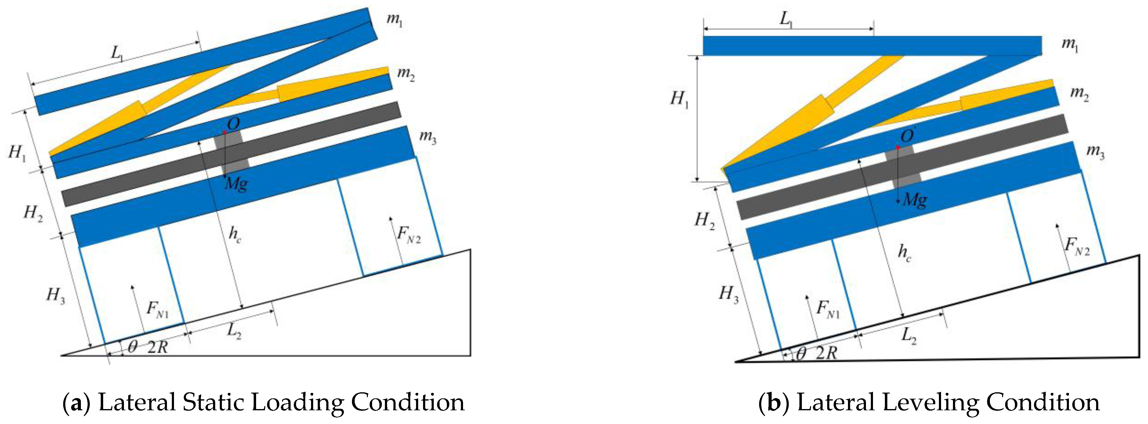
Using the same methodology, the lateral slope stability of the tracked agricultural chassis was thoroughly analyzed. A comprehensive mathematical model for lateral rollover of the entire machine, as depicted in Figure 4, was established, and the lateral rollover angle was subsequently computed.
The lateral rollover angle under static lateral loading is derived from the moment equilibrium equation (Equation (14)), as articulated in Equation (15):
M g h c sin θ + F N 2 2 L 2 + 2 R M g cos θ L 2 + R = 0
θ = arctan ( L 2 + R ) m 1 + m 2 + m 3 m 1 H 1 + H 2 + H 3 + m 2 H 2 + H 3 + m 3 H 3
In the formula, L 2 = 0.3   m ,   R = 0.15   m .
In a similar manner, the lateral rollover angle during leveling operations is calculated utilizing the moment equilibrium equation (Equation (16)), as delineated in Equation (17).
M g sin θ h c + F R 2 L 2 + 2 R M g cos θ L 2 + R + Δ X z 1 = 0
θ = arctan L 2 + R + Δ X z 1 h c = arctan M L 2 + R + m 1 H 1 2 sin θ m 1 H 1 2 cos θ + H 2 + H 3 + m 2 H 2 + H 3 + m 3 H 3
The lateral rollover angles under both non-leveling and leveling conditions, calculated using Equations (15) and (17), are presented in Table 2. These findings validate that the design specifications are met—specifically, there is no rollover at the maximum lateral slope of 20°. Moreover, they demonstrate a significant enhancement in the rollover angle threshold as a result of leveling. This improvement facilitates an extension of the chassis’ operational limits regarding maximum lateral slope.

2.2.4. Load Stability Analysis

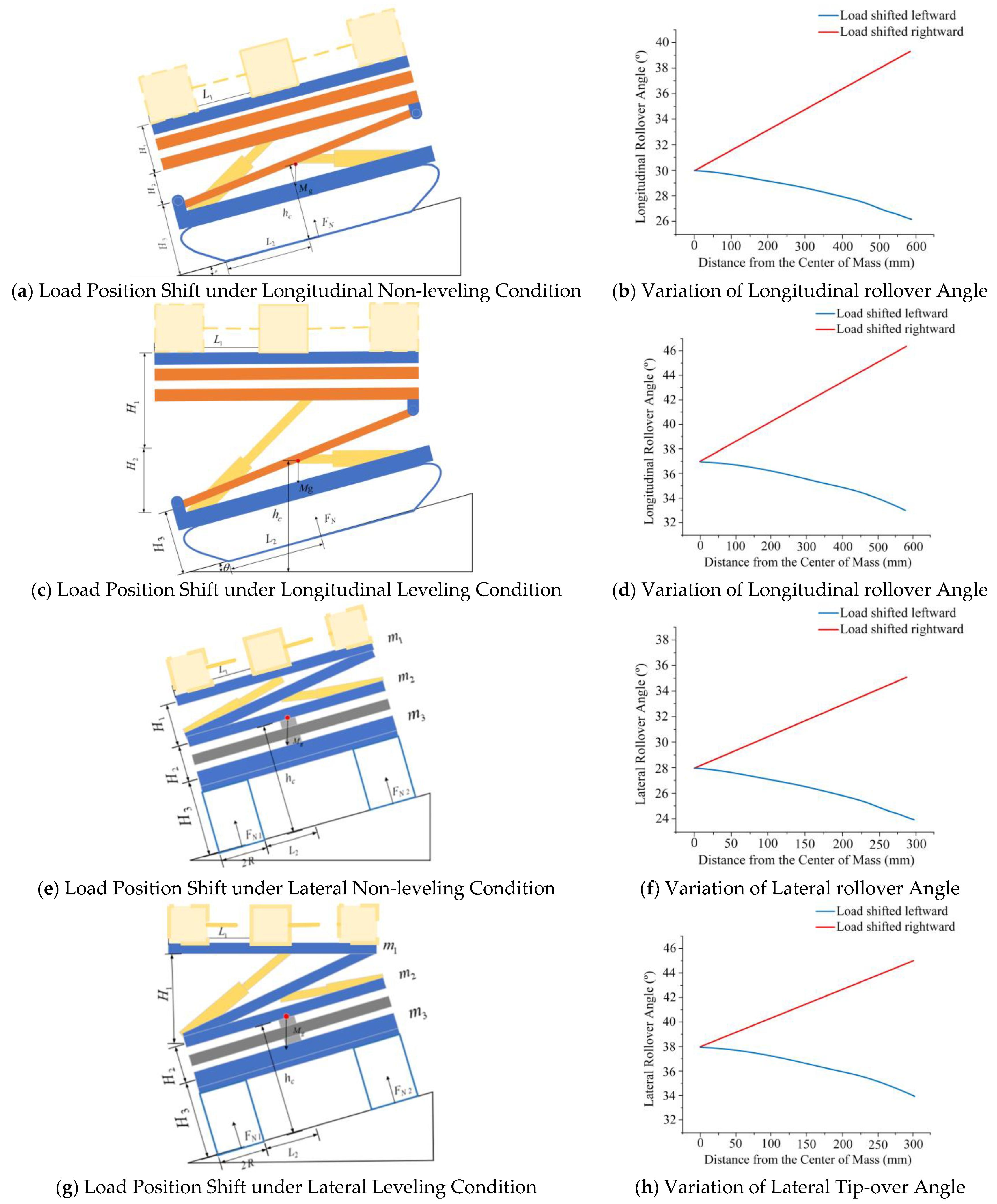
During the operation of the tracked agricultural chassis, the loading of materials on the upper frame leads to a shift in the overall center of mass, which in turn affects the rollover angle of the entire system and presents challenges to both traveling and operational stability. Taking a 200 kg load as a representative case, this study systematically examines the variation in rollover angle under four distinct working conditions—longitudinal non-leveling, longitudinal leveling, lateral non-leveling, and lateral leveling—when the load is placed at different positions on the upper frame, based on the aforementioned formulas. The results are presented in Figure 5.
As illustrated in the figure, the chassis demonstrates effective suppression of rollover angle fluctuations induced by load position variations under both longitudinal and lateral leveling modes, thereby exhibiting robust adaptive stability and anti-sideslip performance.

3. Design of Adaptive Sliding Mode Control Strategy

3.1. Virtual Prototype Model

3.1.1. Three-Dimensional Model of the Entire Machine

A virtual prototype 3D model of the tracked agricultural chassis was developed in SolidWorks 2024, integrating key components such as the locomotion chassis, power system, control system, leveling mechanism, transmission system, and work platform.
To achieve a balance between simulation accuracy and computational efficiency while mitigating the challenges posed by excessive model complexity during dynamic modeling and numerical resolution processes, this study employs a key-feature-based model simplification strategy. This approach preserves the fundamental mechanical transmission structure while systematically reducing overall model complexity. The modeling workflow is outlined as follows:
(1) Body Frame Modeling:
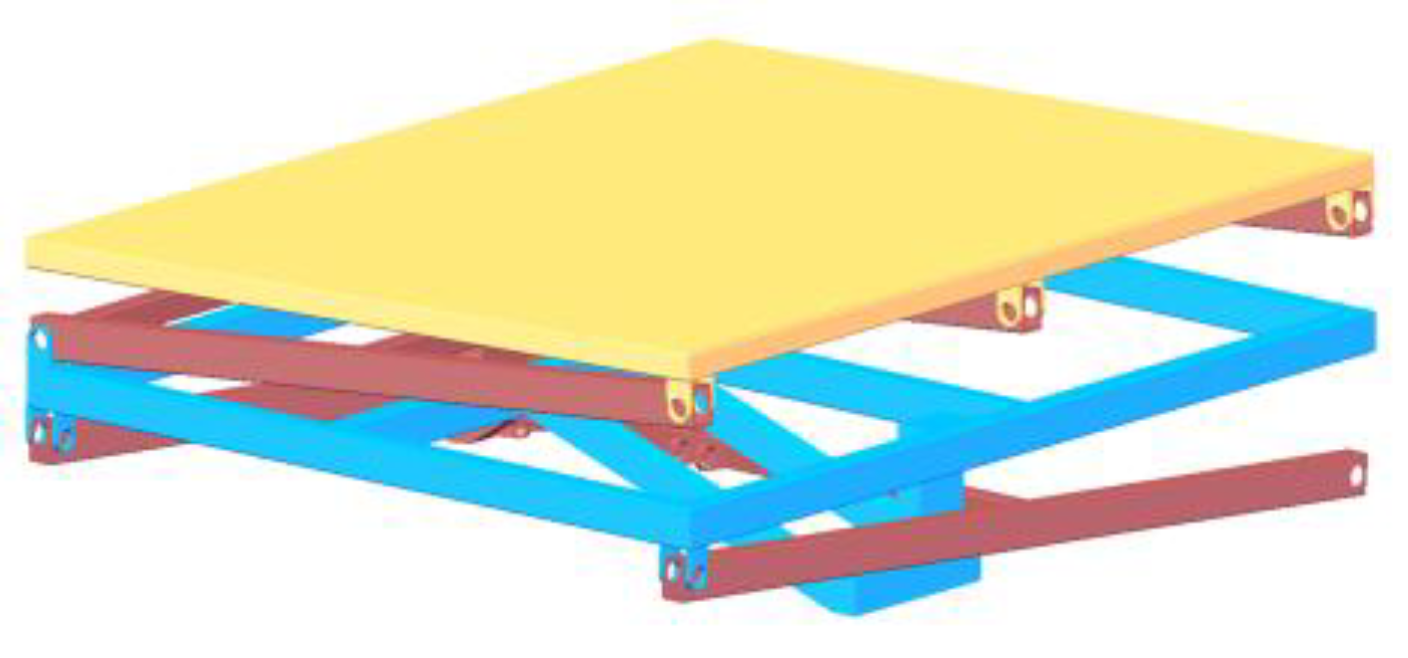
As the primary control target for the leveling system and the mounting structure for operational equipment, it is essential that the body frame maintains a horizontal orientation on sloped terrain. The model encompasses the body frame, upper support, intermediate frame, and lower support. These components are interconnected through hinge mechanisms to form a foundational framework supporting longitudinal, lateral, and omnidirectional leveling (Figure 6). This structural configuration serves as the target for posture adjustments via controlled extension and retraction of servo-electric cylinders.
(2) Chassis Simplification:
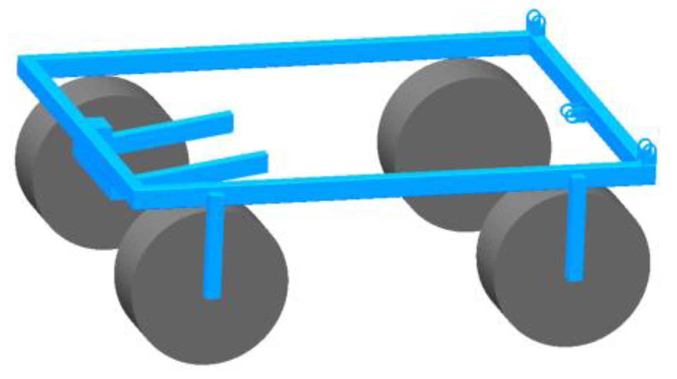
The chassis operates as a carrier for the tracked locomotion mechanism while integrating various subsystems that contribute to its inherent structural complexity. In preserving essential mechanical characteristics within this model simplification process: auxiliary components not impacting device dynamics were removed; complex geometries of tracked locomotion were approximated using an equivalent wheeled configuration (Figure 7).
(3) Modeling of Servo-electric Cylinder Actuator:
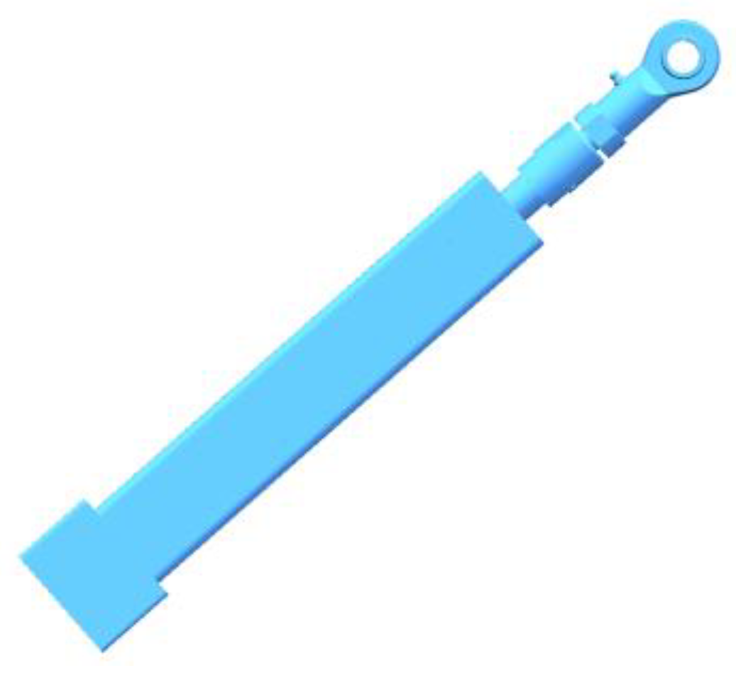
In the electromechanical leveling system, four servo-electric cylinders serve as the actuation mechanism-two are designated for lateral leveling and two for longitudinal leveling. Geometrically accurate models have been constructed and hinge-connected between: the body frame and intermediate frame; as well as the intermediate frame and chassis frame (Figure 8). The extension and retraction capabilities of these cylinders facilitate precise control over both the posture of the frame and the horizontality of the work surface.
A representation of the final equivalent model for the tracked agricultural chassis is depicted in Figure 9.

3.1.2. Hilly Road Surface Model

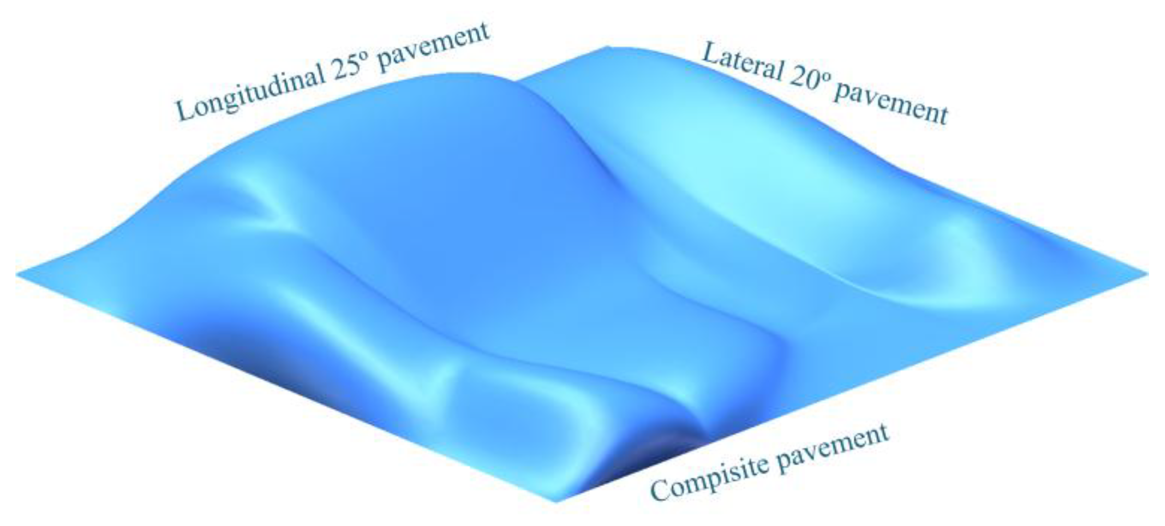
Aligned with the established comprehensive design requirements for the omnidirectional leveling system of tracked agricultural chassis, this study’s primary objective is to achieve adaptive leveling functionality in hilly and mountainous operating conditions. The key performance criteria encompass lateral leveling angles of ±20° and longitudinal leveling angles of ±25°. Following the virtual prototype modeling phase, corresponding terrain models were developed to assess the dynamic response characteristics of the system: (a) Longitudinal extreme condition: 25° sloped terrain; (b) Lateral extreme condition: 20° sloped terrain; (c) Compound extreme condition: Omnidirectional sloped terrain featuring a combined inclination of 25° longitudinally and 20° laterally. These terrain models facilitate an accurate simulation of both kinematic behavior and leveling control performance for the tracked chassis across various types of terrain surfaces. The configuration of these terrain models is illustrated in Figure 10.

3.2. Mathematical Model for the Servo-Electric Cylinder

Based on the principle of dynamic equivalence, this study presents a refined model of the ball screw feed system, as illustrated in Figure 11. The model employs a dual-mass modeling approach that achieves structural simplification via systematic parameter equivalence while preserving key dynamic characteristics. In the process of model development, equivalent representations for both system inertia distribution and elastic deformation behavior are incorporated. Two kinematically coupled mass units are utilized to effectively capture the core dynamic response of the system. This method ensures an accurate representation of the physical system while enhancing computational efficiency through model order reduction. Furthermore, it establishes a theoretical foundation for analyzing system dynamics and designing advanced control algorithms.
The dynamic equations for the ball screw rotational-to-linear motion model are formulated based on the angular momentum theorem:
J x θ ¨ = c x θ ˙ + c 2 i ( x ˙ i θ ˙ ) + k i ( x i θ ) + τ m + τ d
M p x ¨ = c p x ˙ + c 2 ( l θ ˙ x ˙ ) + k ( l θ x ) + F d
In the equations, J x denotes the equivalent inertia of the rotating components; c x represents the equivalent damping of the motor spindle and bearing assembly; k indicates the axial equivalent stiffness of the system; i is the transmission ratio; M p refers to the equivalent mass of the axial components, including the worktable and workpiece; c p symbolizes the damping coefficient of the linear guides; c 2 stands for the relative axial viscous damping between the screw and nut; x corresponds to the linear displacement of the worktable; τ d represents the disturbance torque; F d denotes the disturbance force; and τ m indicates the motor torque.
To facilitate the derivation of the dynamic equations, this study employs the transmission ratio of the ball screw mechanism to transform the original rotational-linear coupled model into an equivalent linear motion model. The resulting configuration of the ball screw system is depicted as an equivalent linear-linear motion representation in Figure 12.
The dynamic equations for the ball screw linear motion model are formulated based on the principle of angular momentum.
m 1 0 0 m 2 x ¨ 1 x ¨ 2 + c 1 + c 2 c 2 c 2 c 2 + c 3 x ˙ 1 x ˙ 2 + k k k k x 1 x 2 = u 0 + d i d t
To facilitate intuitive mathematical modeling and subsequent sliding mode control design, this study converts rotational motion parameters into their linear equivalents using the transmission ratio i = l / 2 π . Specifically: The equivalent axial mass of rotating components is defined as m 1 = J x / ( l / 2 π ) 2 ; The equivalent axial damping coefficient is expressed as c 1 = c x / ( l / 2 π ) 2 ; The equivalent linear displacement of the screw is given by x 1 = l θ / 2 π ; The axial component mass remains m 2 = M p ; The damping coefficient of the linear guides is retained as c 3 = c p ; The worktable displacement x 2 = x preserves its original definition. The terms d i and d t represent external disturbances on the motor side and worktable, respectively, while u refers to the control input applied at the motor side. (In the state-space model, the generalized input u corresponds to the physical input τ m , and the generalized disturbances d i and d t correspond to the physical disturbances τ d and F d , respectively.)
The dynamic model of the dual-degree-of-freedom system is expressed in matrix equation form through a state-space representation:
x ˙ = A x + B u + D d y = C x
x ˙ 2 x ¨ 2 x ˙ 1 x ¨ 1 = 0 1 0 0 k m 2 c 2 + c 3 m 2 k m 2 c 2 m 2 0 0 0 1 k m 1 c 2 m 1 k m 1 c 1 + c 2 m 1 x 2 x ˙ 2 x 1 x ˙ 1 + 0 0 0 0 0 1 m 2 0 0 0 1 m 1 1 m 1 0 u d j d m
y 1 y 2 = 1 0 0 0 0 0 1 0 x 2 x ˙ 2 x 1 x ˙ 1

3.3. Design of an Adaptive Sliding Mode Control Strategy

3.3.1. Design of a Sliding Mode Controller

Compared to alternative control methods, sliding mode control (SMC) exhibits several distinctive characteristics [41,42,43,44]:
(1) For inherently nonlinear controlled systems, the dynamic behavior of the sliding surface can be engineered to demonstrate linear time-invariant properties;
(2) The dynamics of the sliding surface are solely determined by the controller parameters and remain independent of the mathematical model of the plant;
(3) Once the system enters into sliding mode, it showcases robustness against parameter uncertainties and external disturbances;
(4) The order of the system’s differential equations can be reduced.
Based on Equations (20)–(23), the dual-degree-of-freedom ball screw feed system is articulated as follows:
x ¨ 2 = w 1 + g 1 d t x ¨ 1 = w 2 + g 2 u + d i
where
w 1 = k m 2 x 1 + k m 2 x 2 c 2 m 2 x ˙ 1 + c 2 + c 3 m 2 , g 1 = 1 m 2 w 2 = k m 1 x 1 + k m 1 x 2 + c 1 + c 2 m 1 x ˙ 1 + c 2 m 1 x ˙ 2 , g 1 = 1 m 1
To improve the dynamic response characteristics during the reaching phase, a methodology for designing an approach law is integrated into the position control framework. Assuming the equivalent linear displacement commands for screw rotation and rigid-body displacement are x 1 r and x 2 r , respectively, the tracking errors are defined as: e 1 = x 2 r x 2 , e 2 = x ˙ 2 r x ˙ 2 , e 3 = x 1 r x 1 , e 4 = x ˙ 1 r x ˙ 1 Differentiation of these expressions yields:
e ˙ 1 = x ˙ 2 r x ˙ 2 = e 2 e ˙ 2 = x ¨ 2 r x ¨ 2 = x ¨ 2 r w 1 g 1 d m e ˙ 3 = x ˙ 1 r x ˙ 1 = e 4 e ˙ 4 = x ¨ 1 r x ¨ 1 = x ¨ 1 r w 2 g 2 u + d j
Within the position control framework, the sliding surface is formulated as follows:
s = y e T = y 4 y 3 y 2 y 1 e 4 e 3 e 2 e 1 T = x 1 e 1 + y 2 e 2 + y 3 e 3 + y 4 e 4
where y i > 0 , i = 1,2 , 3,4 , When s = 0 , y 4 = 0 , yielding: e 4 = y 1 e 1 y 2 e 2 y 3 e 3 .
Define:
E = e 1 e 2 e 3 T
H = 0 1 0 0 0 1 y 1 y 2 y 3
This results in E ˙ = H E . The parameters y 1 , y 2 and y 3 are determined using the pole placement method to ensure that the matrix H satisfies the Hurwitz criterion. This guarantees that the error vector E = e 1 e 2 e 3 T approaches zero as t (i.e., E → 0), and that all eigenvalues of H have negative real parts.
Suitable eigenvalues λ are assigned for the system, which determine the corresponding y values. By adjusting the constant-coefficient matrix y , the trajectory tracking accuracy of the worktable during motion can be effectively improved.
Differentiating the sliding function in Equation (27) yields:
s ˙ = y 1 e ˙ 1 + y 2 e ˙ 2 + y 3 e ˙ 3 + y 4 e ˙ 4 = y 1 e 2 + y 3 e 4 + y 2 x ¨ 2 r + w 1 + y 4 x ¨ 1 r w 2 y 2 m 2 d m 1 m 1 u 1 m 1 d j
According to the theory of sliding mode control, the reachability condition ensures finite-time convergence of system trajectories from arbitrary initial states to a vicinity of the sliding surface. However, it does not impose any restrictions on the dynamic characteristics of the convergence paths. To address this limitation, a method for designing approach laws is employed to enhance dynamic response performance during the reaching phase. The general mathematical formulation can be expressed as follows:
s ˙ = k sign ( s ) f ( s ) , k > 0
This study employs the power-rate approach law derived from Equation (31): s ˙ = k | s | α sign ( s ) Substituting this expression into Equation (31) yields:
y 1 e 2 + y 3 e 4 + y 2 x ¨ 2 r + w 1 + y 4 x ¨ 1 r w 2 y 2 m 2 d m 1 m 1 u 1 m 1 d j = k | s | α   sign   ( s )
The resulting control law is given by:
u = m 1 y 1 e 2 + y 2 x ¨ 2 r + w 1 + y 3 e 4 w 2 + x ¨ 1 r + k s | α sign ( s T
where T = m 1 y 2 / m 2 + d j denotes the aggregate system disturbance.
Thus, the system block diagram is illustrated in Figure 13.

3.3.2. System Stability Verification

The stability of the control system is analyzed using Lyapunov’s direct method. The external disturbance is assumed to be bounded, satisfying τ d i s k . The Lyapunov function is defined as follows (Equation (34)):
V = 1 2 s 2
Differentiating Equation (34) yields:
V ˙ = s s ˙ = s y 1 e 2 + y 3 e 4 + y 2 x ¨ 2 r + w 1 + y 4 x ¨ 1 r w 2 y 2 m 2 d m 1 m 1 u 1 m 1 d j s k s α sign   ( s ) 0
Equation (35) demonstrates that the controlled system converges to a stable state.

3.4. Performance Analysis and Validation

3.4.1. Verification of Omnidirectional Leveling Performance for Crawler-Type Agricultural Chassis

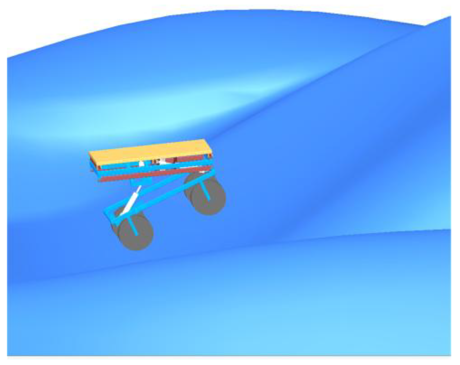
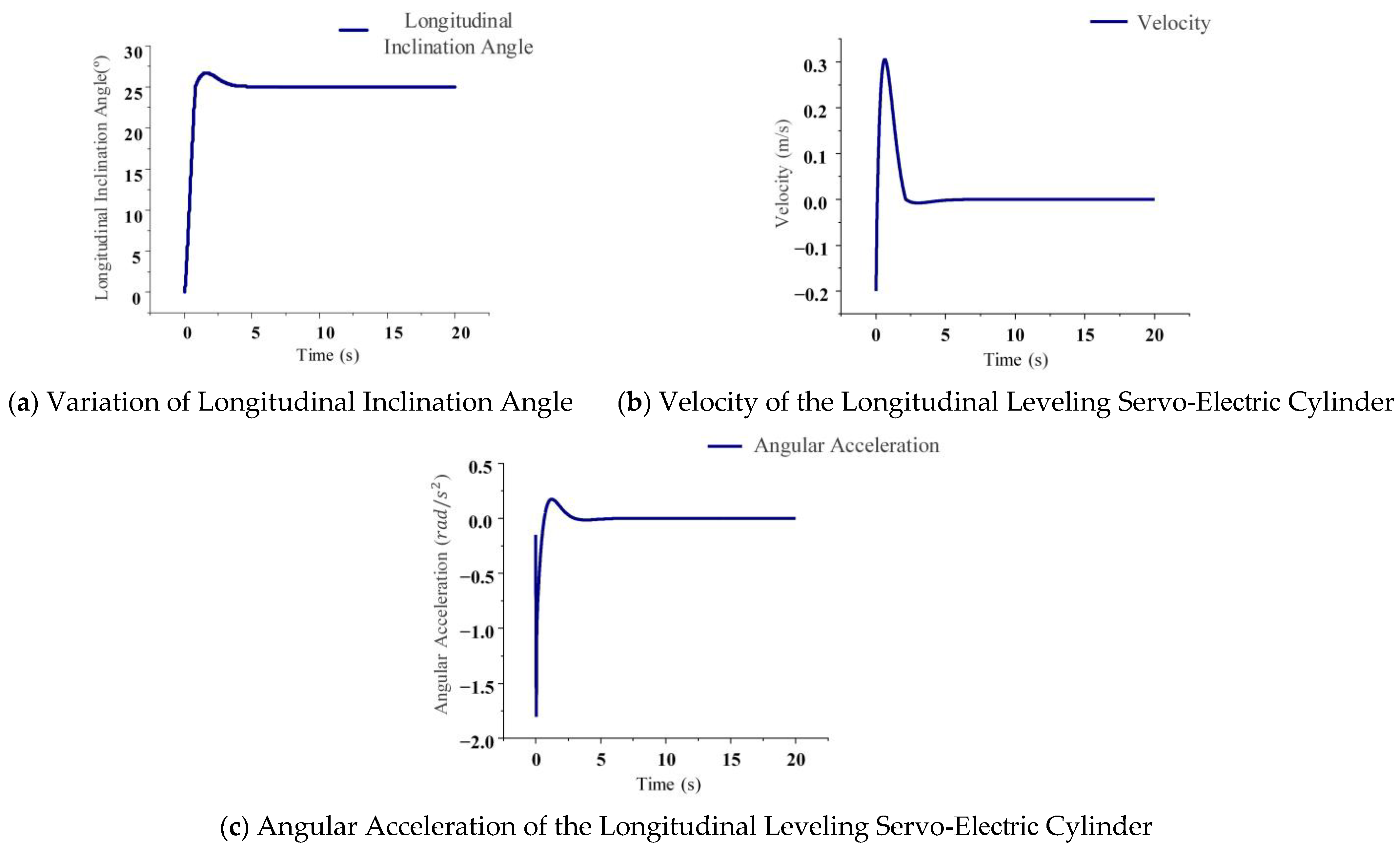
Figure 14 illustrates the simulation results of the tracked agricultural chassis operating on a 25° longitudinal slope. Figure 15 presents the variations in performance associated with the motion of the servo-electric cylinder and the inclination angle of the chassis during longitudinal leveling.
Figure 15a illustrates a 7.2% overshoot (relative to the steady-state value) in the inclination angle of the servo-electric cylinder during 25° longitudinal leveling, with stabilization achieved at 4.76 s. Figure 15b depicts a maximum leveling velocity of 0.317 m/s, while Figure 15c demonstrates a peak angular acceleration of 0.389 rad/s2.
Figure 16 presents the simulation results of the tracked agricultural chassis operating on a 20° lateral slope. Figure 17 illustrates the variations in servo-electric cylinder motion and body inclination angle during lateral leveling, reflecting the system’s dynamic performance.
Figure 17a illustrates an overshoot of 6.8% (relative to the steady-state value) in the inclination angle of the servo-electric cylinder during a 20° lateral leveling process, achieving stabilization at 3.96 s. Figure 17b depicts a maximum leveling velocity of 0.253 m/s, while Figure 17c demonstrates a peak angular acceleration of 0.139 rad/s2.
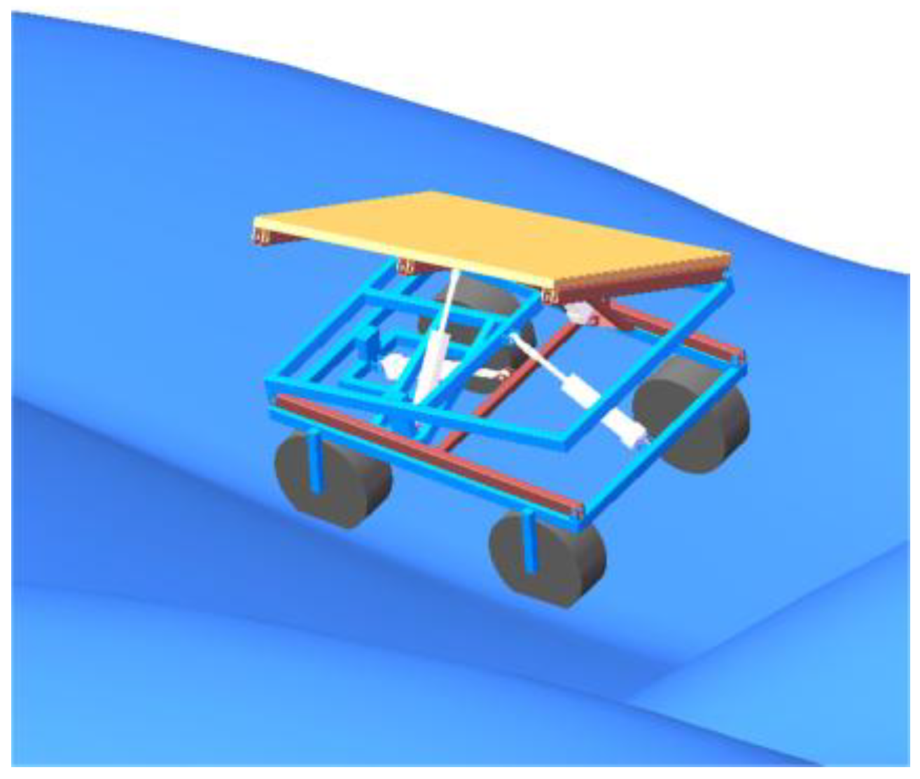
Figure 18 presents the simulation results for the tracked agricultural chassis under combined slope conditions, featuring a longitudinal incline of 25° and a lateral inclination of 20°, thereby indicating its omnidirectional leveling performance.
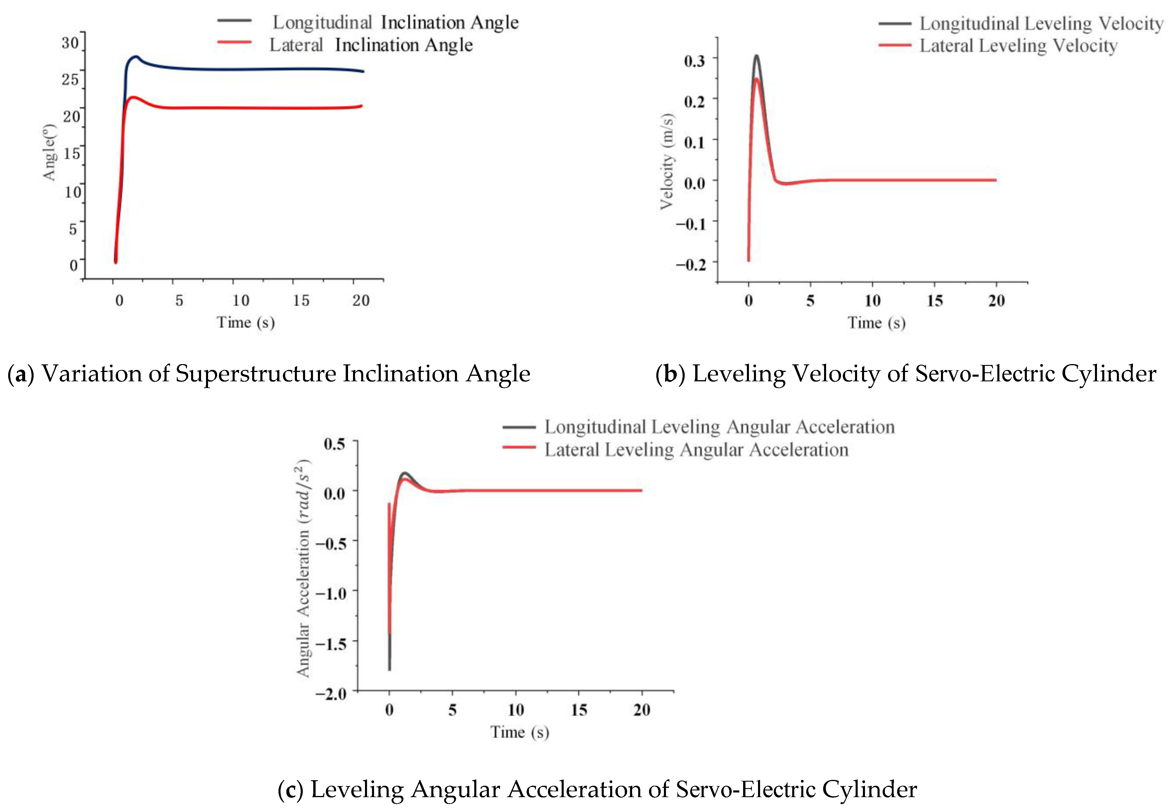
As illustrated in Figure 19, the omnidirectional leveling performance of the crawler-type agricultural chassis exhibits a trend consistent with those presented in Figure 15 and Figure 17. This consistency indicates that the lateral and longitudinal leveling processes remain largely independent during omnidirectional adjustment, which is attributable to the innovative structural design that effectively decouples the control mechanisms in both directions. Consequently, the overall omnidirectional leveling behavior closely aligns with the results of single-direction simulations, thereby further substantiating the rationality and superiority of the chassis design.
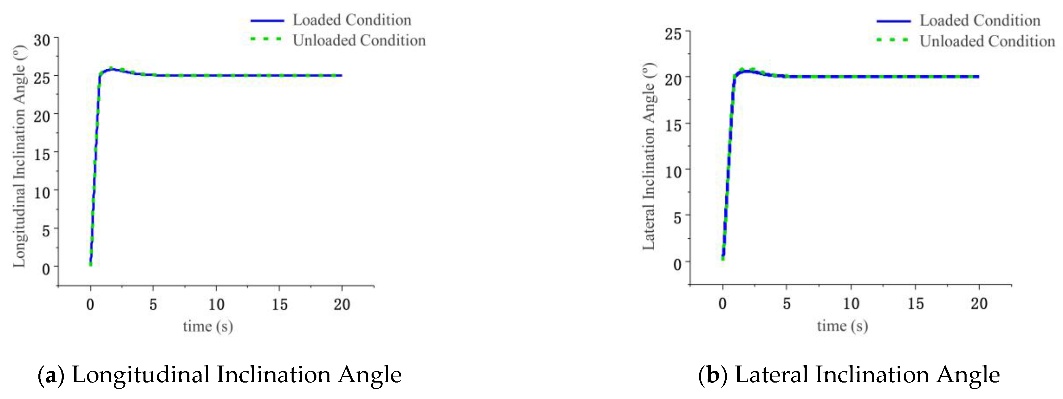
Based on the preceding stability analysis of the chassis under loaded conditions, it is evident that during lateral leveling, the lateral roll angle reaches its minimum value when the load is positioned at the rightmost location. Conversely, during longitudinal leveling, the lateral roll angle is minimized when the load is placed at the leftmost position. Simulation analyses were carried out for these two representative operating conditions: longitudinal leveling with a 200 kg load located at the left end, and lateral leveling with a 200 kg load positioned at the right end (Figure 20). The corresponding leveling performance curves are presented in Figure 21.
Figure 21a depicts the variation in the longitudinal inclination angle of the tracked agricultural chassis under loaded conditions during longitudinal leveling. During the 25° longitudinal leveling process, the overshoot of the longitudinal inclination angle in the loaded condition is 0.3° greater than that observed in the unloaded condition. Figure 21b illustrates the variation in the lateral inclination angle under loaded conditions during lateral leveling. Throughout the 20° lateral leveling operation, the overshoot of the lateral inclination angle in the loaded case remains 0.2° higher compared to the unloaded scenario. Despite these differences, the tracked agricultural chassis successfully completes the leveling tasks under both longitudinal and lateral loaded conditions, with inclination angle variation trends closely aligning with those observed in the unloaded state, thereby demonstrating the reliability and performance superiority of the chassis design.

3.4.2. Comparative Performance Analysis of the Omnidirectional Leveling System for Tracked Agricultural Chassis

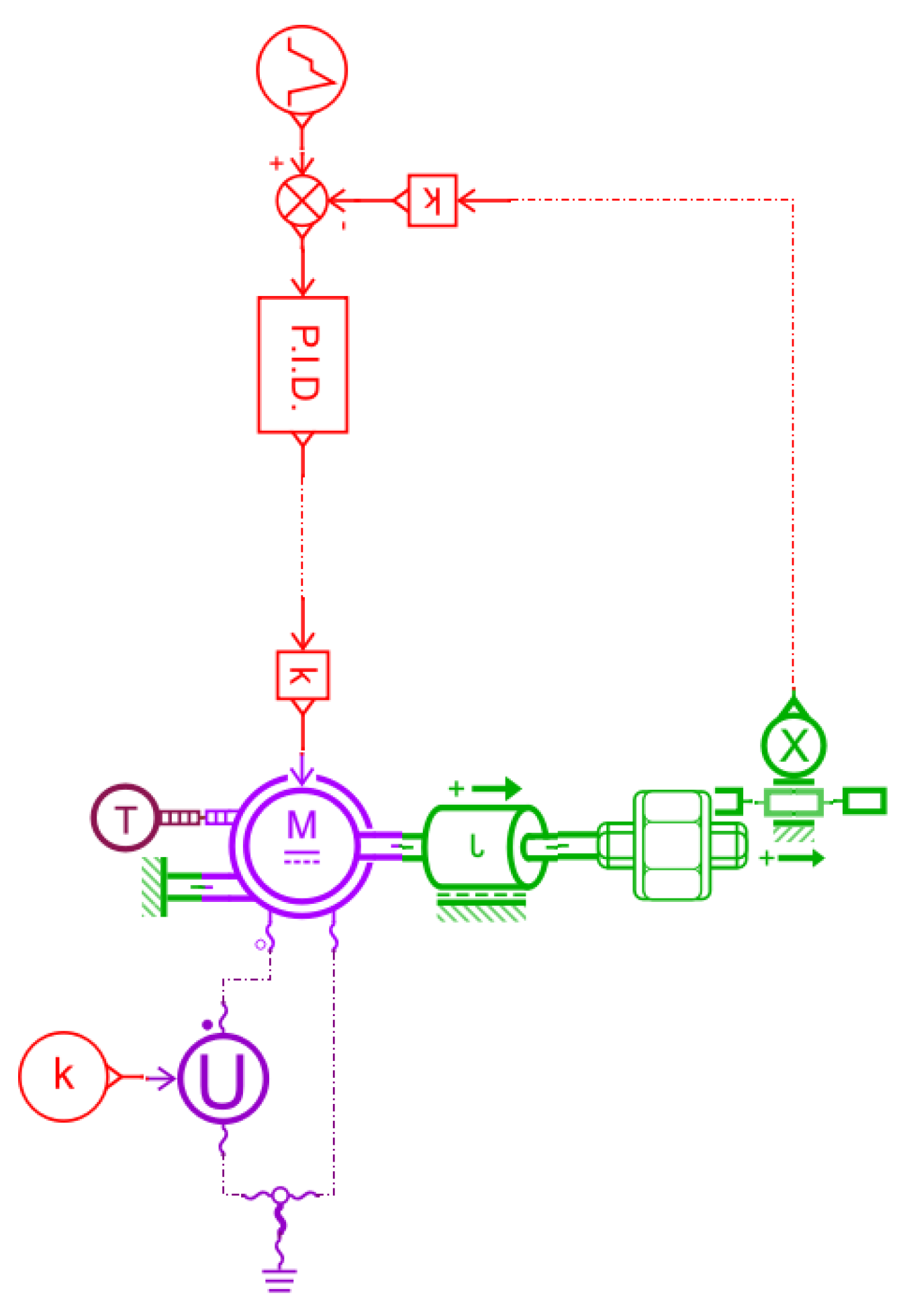
This study employs a comprehensive multi-software co-simulation framework. Specifically, ADAMS (v2020) is utilized to create the complete multibody dynamics model; AMESim (v2023) is tasked with developing the servo-electric cylinder system model; Simulink (MATLAB v2023b) serves to implement the control system model; and Visual Studio (v2022) supports the integration of the system-level environment. Consequently, electro-hydraulic-mechanical co-simulation is achieved. Figure 22 illustrates the servo-electric cylinder model constructed using AMESim’s Mechanical, Electrical, and Signal libraries.
In the figure, k represents a constant; T denotes the thermal temperature source; M stands for electric drive and torque control; J refers to the rotating load dual-port element; X indicates the displacement sensor; and U represents the controlled voltage source.
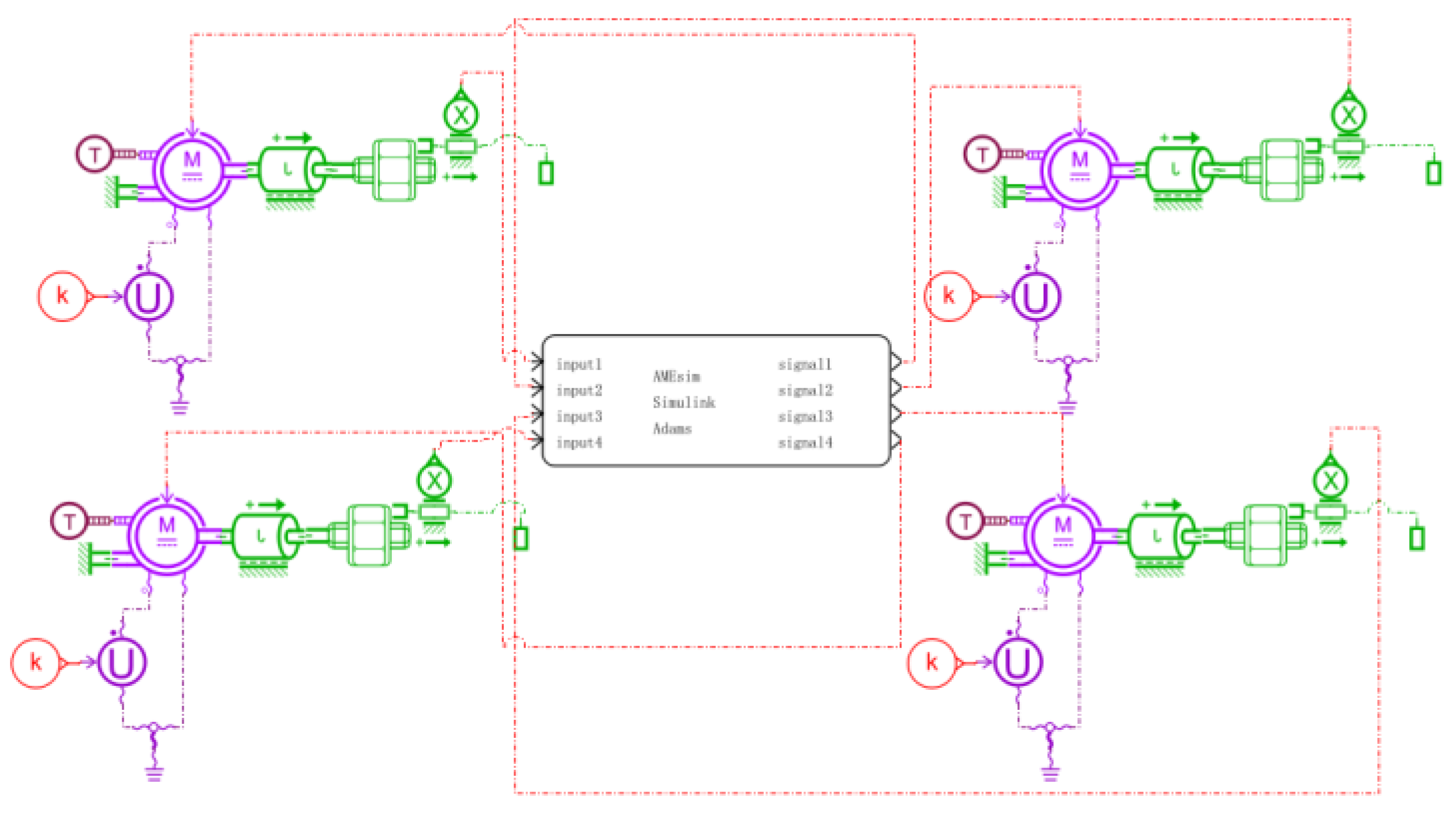
Building on the foundation of the single-cylinder model, this study presents a co-simulation framework that incorporates four servo-electric cylinders for the tracked agricultural chassis, as illustrated in Figure 23. The controller model is implemented using MATLAB/Simulink, and an integrated co-simulation platform is established to connect AMESim, Simulink, and ADAMS, as demonstrated in Figure 24.
The static rollover threshold analysis presented in Section 2.2 demonstrates that the chassis structure possesses a high degree of inherent stability. This characteristic serves as a solid foundation for the adaptive sliding mode control (ASMC) strategy proposed in this study, enabling rapid and robust tracking performance. The significant stability margin provided by the mechanical design substantially expands the feasible design space for the control algorithm. To evaluate the leveling performance of ASMC in comparison with PID control, a co-simulation integrating electromechanical systems was performed under conditions of a 25° longitudinal slope and a 20° lateral slope. The comprehensive omnidirectional leveling performance is summarized in Figure 25.
Figure 25a,b illustrate the variations in body inclination angles during longitudinal leveling at 25° and lateral leveling at 20°, respectively. With the implementation of sliding mode control (SMC), longitudinal leveling stabilizes within 2.47 s, which is an improvement of 1.12 s compared to PID control, while lateral leveling reaches stabilization in just 2.39 s, showing a reduction of 0.95 s relative to PID control. Furthermore, SMC effectively decreases the overshoot in both longitudinal and lateral inclination by 2.21° and 1.86°, respectively, when benchmarked against PID control.
Figure 25c,d depict the velocity profiles associated with the leveling process for both the aforementioned configurations—longitudinal at 25° and lateral at 20°. The application of SMC results in a longitudinal velocity that is approximately 1.5 times greater, as well as a lateral velocity that exceeds those achieved through PID control by about 1.3 times.
Figure 25e,f present data on angular acceleration recorded during both levels of operation: longitudinal at 25° and lateral at 20°. Notably, SMC reduces angular acceleration for longitudinal movement by an impressive margin of 15.8% while achieving a reduction of approximately 17.1% in lateral angular acceleration compared to traditional PID approaches.
These comparative analyses unequivocally underscore the superiority of sliding mode control over PID methodology within omnidirectional leveling systems; evidenced by reduced overshoot magnitudes alongside quicker stabilization times; enhanced velocities during operation; as well as diminished angular accelerations throughout the leveling phase. Consequently, SMC not only augments operational speed but also fortifies stability for tracked agricultural chassis navigating hilly or mountainous terrains.

4. Experimental Verification

4.1. Test Equipment and Protocol

The prototype has a total weight of 800 kg, with dimensions of 1015 mm in height, 1500 mm in length, and 1200 mm in width. It is equipped with a 4 × 12 V 80 Ah lead-acid battery pack (Henan Jinma Storage Battery Co., Ltd., Xinxiang, Hena, China) mounted on the tracked agricultural chassis, which supplies power to both the locomotion and leveling systems, enabling a maximum travel speed of 3 km/h during operation. For posture sensing, dual-axis high-precision ZCT2XXKLCS-AH-XX-7XB tilt sensors (SHANGHAI ZHICHUAN ELECTRONIC TECH CO., LTD, Shanghai, China) are installed beneath the work platform and along the central axis of the chassis. These sensors offer a dynamic measurement accuracy of ±0.05°, allowing for real-time monitoring of the vehicle’s longitudinal and lateral inclination angles as well as the ground slope. The control system is centered around an electromechanical omnidirectional leveling controller based on the STM32F407ZGT6 microprocessor (STMicroelectronics N.V., Shanghai, China). It collects sensor data via CAN bus communication, processes the data using control algorithms, generates voltage control signals for the servo motors, and transmits these signals to the servo drives through dedicated circuits. The actuation system comprises four high-precision KDJ80-T10200-BR-PC-M5-P750 servo-electric cylinders (Shenzhen Kewei Machinery Equipment Co., Ltd., Shenzhen, Guangdong, China). Each cylinder features a designed stroke of 400 mm and is integrated with a 48 V DC servo motor rated at 2000 W, delivering a peak torque of 45 N·m. The system incorporates a ball screw mechanism with an 18 mm lead and a planetary reducer with a 5:1 reduction ratio, achieving a repeat positioning accuracy of ± 0.02 mm. This level of precision satisfies the requirements for high-frequency dynamic leveling on uneven terrain. The servo drives regulate motor rotation, which is converted into precise linear motion through the ball screw mechanism, thereby enabling dynamic leveling of the vehicle body. The prototype and associated components are illustrated in Figure 26.
To assess the operational performance of the tracked agricultural chassis leveling system, both static and dynamic tests were conducted on the prototype. Static tests were performed on level ground in an outdoor setting. Manual leveling control was activated while tilt sensors continuously monitored the body attitude angles, thereby validating the fundamental leveling functionality. Dynamic tests were executed on natural slopes with longitudinal inclinations of 25° and lateral inclinations of 20°. The prototype navigated at a speed of 3 m/s in activated auto-leveling mode. On-board data loggers recorded longitudinal and lateral attitude data for subsequent analysis regarding slope leveling response.

4.2. Static Leveling Tests

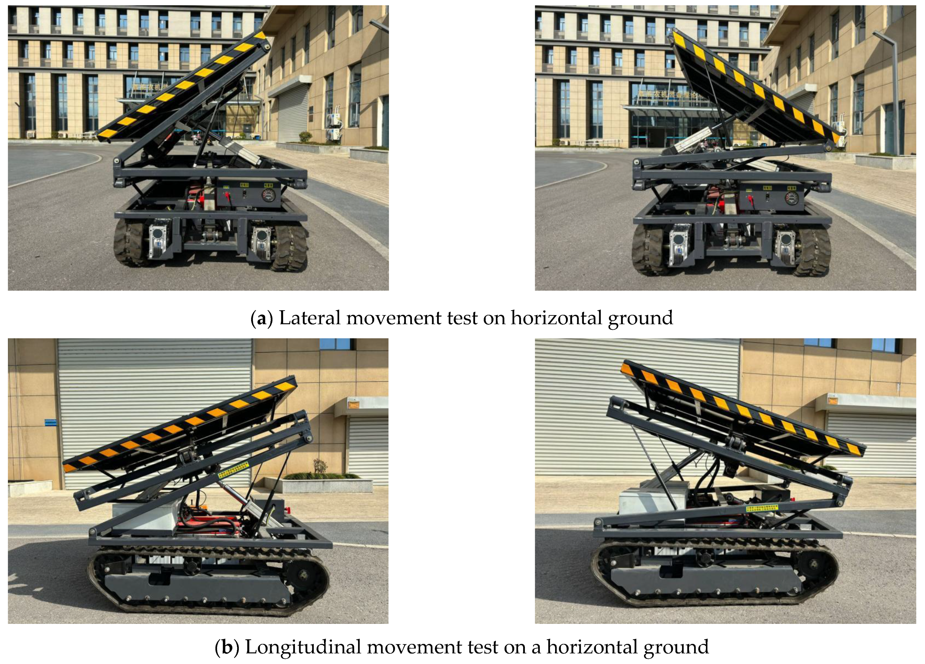
Static tests were carried out with the apparatus positioned on level ground, executing independent stationary leveling assessments for both lateral and longitudinal movements, as depicted in Figure 27.
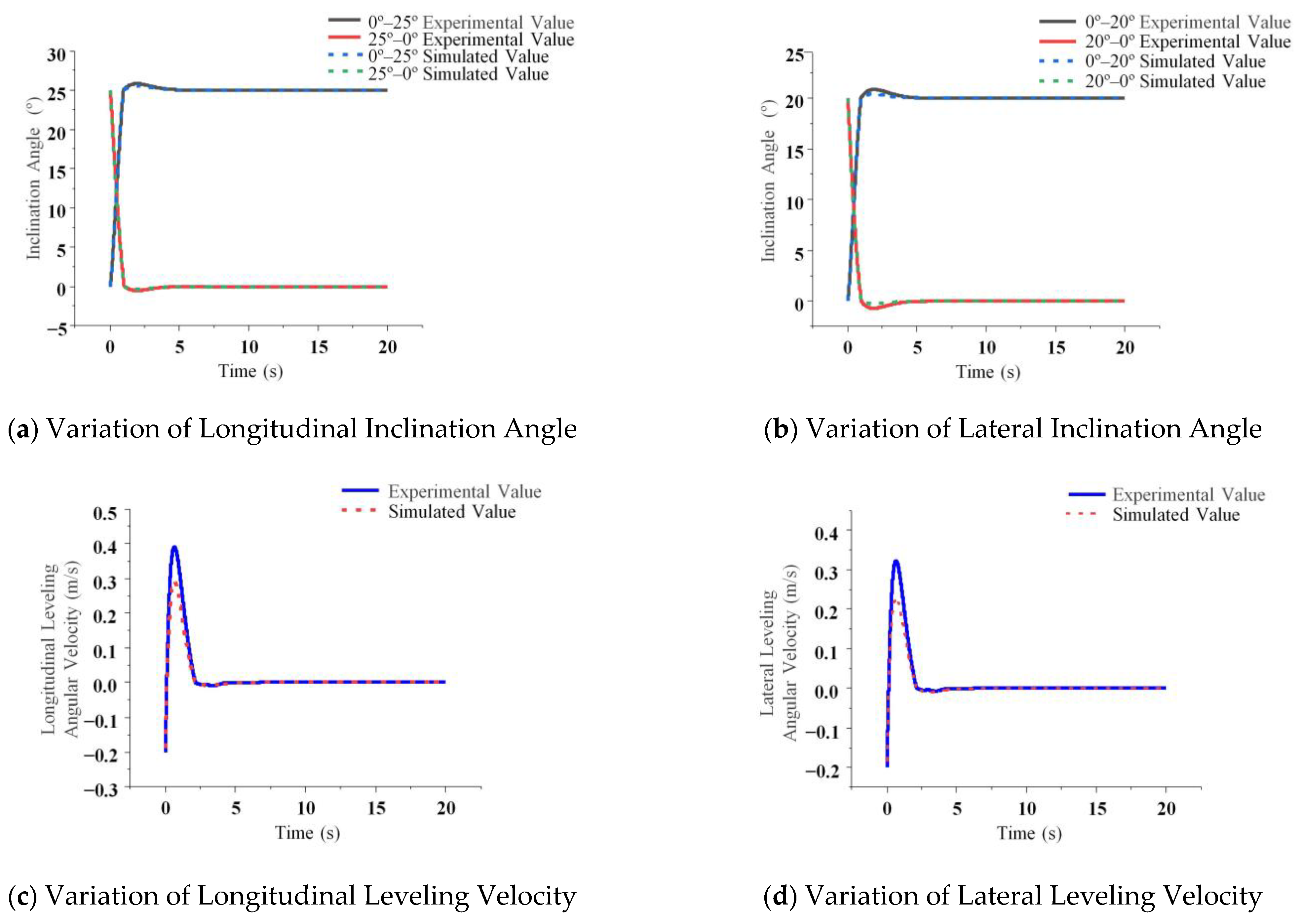
Figure 28 presents the variations in body inclination angle and leveling velocity observed during the static leveling tests conducted on the prototype.
The longitudinal and lateral inclination angles exhibited overshoots of 0.9° and 1.2°, respectively, with stabilization achieved within 2.8 s and 2.6 s. The variation in leveling speed demonstrated that the maximum longitudinal and lateral leveling speeds reached 0.39 m/s and 0.32 m/s, respectively. Experimental results confirm that the system is capable of achieving effective adaptive leveling on sloped terrain, with an average deviation of 7.2% and a maximum deviation of 14.75% relative to simulation outcomes. To assess the statistical stability of the experimental findings, static leveling tests were repeated five times. The standard deviations of overshoot and stabilization time were below 0.15° and 0.2 s, respectively, reflecting strong repeatability and consistency of the results, thereby validating the system’s effectiveness and performance superiority. Given the narrow error margins and concentrated data distribution, the values reported in this study represent the arithmetic means of the repeated trials.

4.3. Dynamic Leveling Tests

4.3.1. One-Way Leveling Test

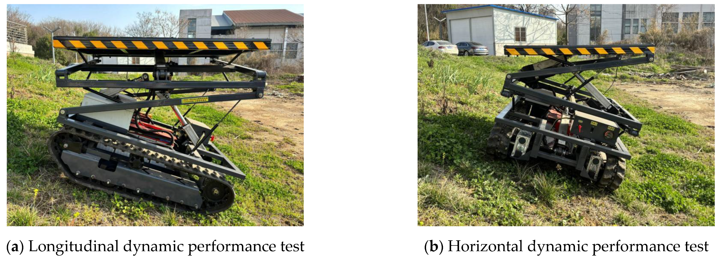
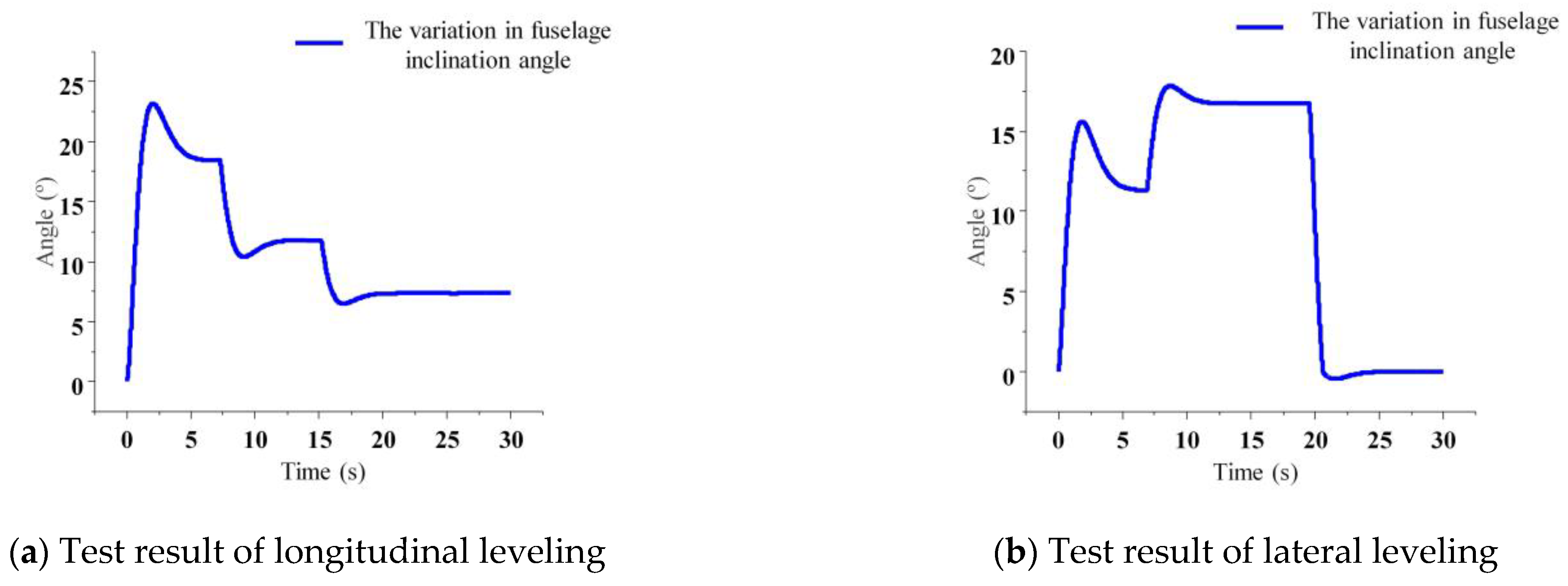
The prototype was positioned on a natural longitudinal slope with the auto-leveling system engaged, and the travel speed maintained at 3 km/h. The test site is depicted in Figure 29a. Figure 30a presents the variations in inclination angle observed during the dynamic longitudinal leveling tests. The longitudinal leveling tests demonstrated that upon entering the steep slope section, the longitudinal inclination angle of the chassis exhibited a significant change, reaching a maximum of 23.8°. As the slope gradient decreased, the chassis initiated counter-directional leveling adjustments to restore equilibrium. The test was conducted three times under consistent road conditions, with variations in key performance indicators—such as maximum inclination angle and stabilization time—remaining within 5%. This consistency confirms the chassis’s capability to effectively maintain longitudinal stability under varying slope conditions.
Similarly, the prototype was placed on a natural lateral slope with the auto-leveling system activated and maintained at a travel speed of 3 km/h. The test site is shown in Figure 29b. Figure 30b illustrates the variations in inclination angle recorded during dynamic lateral leveling tests. The lateral leveling test results demonstrated that upon entering the steep slope section, the lateral inclination angle of the chassis underwent a significant change, reaching a maximum of 17.6°. As the slope gradient decreased, the system executed counter-directional leveling adjustments to compensate for the lateral tilt. The test was conducted three times under identical road conditions, with highly consistent system responses observed across all trials. These results confirm the robustness of the control strategy and validate the chassis’s ability to effectively maintain lateral stability under varying terrain conditions.

4.3.2. Omnidirectional Dynamic Performance Test

The prototype was positioned on a natural composite slope with longitudinal inclinations of 25° and lateral inclinations of 20°, with the auto-leveling system engaged and the travel speed maintained at 3 km/h. The test site is depicted in Figure 31.
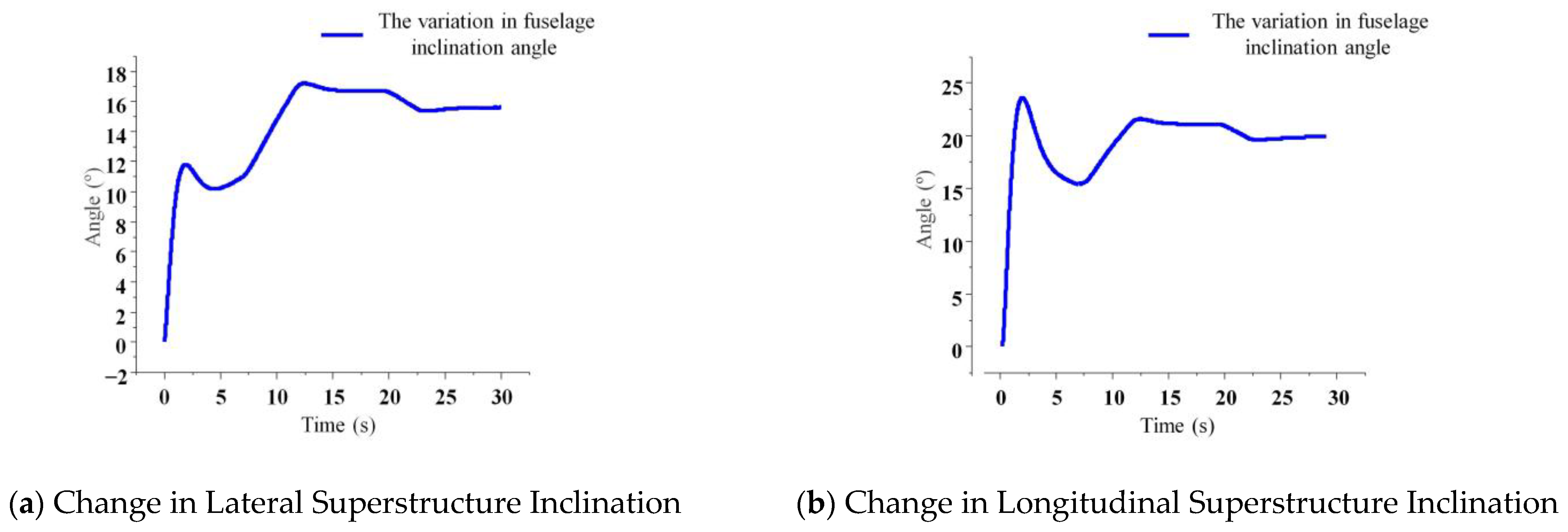
Figure 32 illustrates the inclination angle variations observed during the dynamic omnidirectional leveling tests.
As illustrated in Figure 32a,b, during the omnidirectional leveling tests, both the lateral and longitudinal inclination angles of the chassis were adjusted to match the road slope—achieving a horizontal operating platform—within 3 s, even in the presence of abrupt slope changes. The system demonstrated rapid response to terrain variations. The dynamic tests exhibited high reproducibility, and through multiple experimental repetitions, the leveling process was confirmed to be both stable and reliable. These results validate the chassis’s effectiveness in improving attitude control and enhancing traveling balance performance.

5. Conclusions

This study introduces an omnidirectional leveling system for tracked agricultural chassis, utilizing adaptive sliding mode control (ASMC). A co-simulation model and a comprehensive testing platform were developed to assess the leveling performance of the system.
(1) Simulation results indicate that during 25° longitudinal and 20° lateral leveling, ASMC significantly exceeds the performance of PID control. Specifically, the longitudinal stabilization time is reduced to 2.47 s, representing an improvement of 1.12 s; the lateral stabilization time decreases to 2.39 s, reflecting a reduction of 0.95 s; and longitudinal inclination overshoot is diminished by 2.21°, while lateral overshoot decreases by 1.86°. Additionally, both longitudinal and lateral leveling velocities are enhanced by factors of 1.5 and 1.3 respectively; moreover, reductions in longitudinal and lateral angular accelerations are observed at rates of 15.8% and 17.1%, respectively. These findings substantiate the superiority of ASMC over PID in terms of response speed, control precision, and dynamic stability.
(2) Static tests reveal that post-leveling angular inclinations exhibit overshoots reaching values of 0.9° for longitudinal angles and 1.2° for lateral angles, with stabilization achieved within periods of 2.8 s and 2.6 s correspondingly. The peak velocities attained during longitudinal and lateral leveling register at approximately 0.39 m/s and 0.32 m/s. These outcomes validate the effective adaptive leveling capability demonstrated by the system on inclined surfaces, resulting in a mean error margin of 7.2% alongside a maximum deviation rate totaling 14.75% when compared against simulation data.
(3) Dynamic tests conducted at a travel speed of 3 km/h on natural slopes reveal the following findings: The roll and pitch angles increase significantly upon entering steep slope segments, reaching peak values of 17.6° and 23.8°, respectively; a reverse leveling action is initiated as the gradient of the slope decreases; the roll and pitch angles converge to align with the terrain slope, achieving platform horizontality within a span of 3 s; and the system exhibits rapid responsiveness to sudden variations in slope conditions. These observations indicate that the system effectively mitigates attitude deviations and enhances stability during field operations.

Author Contributions

Data curation, X.Q.; Formal analysis, X.C. and Y.M.; Funding acquisition, R.W.; Investigation, X.C. and Y.M.; Methodology, R.D.; Project administration, R.W.; Resources, R.D.; Software, X.Q.; Supervision, A.L. and Z.G.; Validation, X.Q. and A.L.; Writing—original draft, X.Q.; Writing–review & editing, R.D., R.W. and Z.G. All authors have read and agreed to the published version of the manuscript.

Funding

This research was supported by the National Key Research and Development Program of China (2023YFB2504500), the National Natural Science Foundation Project of China (52472410), and the Project of College of Agricultural Engineering, Jiangsu University (NZXB20210101).

Data Availability Statement

Data are available on request due to restrictions, e.g., privacy or ethical. The data presented in this study are available on request from the corresponding author.

Conflicts of Interest

Author Zhongyang Guo was employed by the company Jiangsu Chaoli Electric Manufacture Co., Ltd. The remaining authors declare that the research was conducted in the absence of any commercial or financial relationships that could be construed as a potential conflict of interest.

References

  1. Sun, J.; Liu, Z.; Yang, F.; Sun, Q.; Liu, Q.; Luo, P. Research Review of Agricultural Equipment and Slope Operation Key Technologies in Hilly and Mountains Region. Nongye Jixie Xuebao Trans. Chin. Soc. Agric. Mach. 2023, 54, 1–18. [Google Scholar] [CrossRef]
  2. Li, H.; Chen, L.; Zhang, Z. A Study on the Utilization Rate and Influencing Factors of Small Agricultural Machinery: Evidence from 10 Hilly and Mountainous Provinces in China. Agriculture 2023, 13, 51. [Google Scholar] [CrossRef]
  3. Yang, M.; Li, M.; Luo, X. 50 Years of Agricultural Mechanization in China. AMA-Agric. Mech. Asia Afr. Lat. Am. 2020, 51, 86–92. [Google Scholar]
  4. Wang, B.; Du, X.; Wang, Y.; Mao, H. Multi-Machine Collaboration Realization Conditions and Precise and Efficient Production Mode of Intelligent Agricultural Machinery. Int. J. Agric. Biol. Eng. 2024, 17, 27–36. [Google Scholar] [CrossRef]
  5. Zhang, F.; Teng, S.; Wang, Y.; Guo, Z.; Wang, J.; Xu, R. Design of Bionic Goat Quadruped Robot Mechanism and Walking Gait Planning. Int. J. Agric. Biol. Eng. 2020, 13, 32–39. [Google Scholar] [CrossRef]
  6. Jin, Y.; Liu, J.; Xu, Z.; Yuan, S.; Li, P.; Wang, J. Development Status and Trend of Agricultural Robot Technology. Int. J. Agric. Biol. Eng. 2021, 14, 1–19. [Google Scholar] [CrossRef]
  7. Yu, Y.; Wang, G.; Tang, Z.; Cao, Y.; Zhao, Y. Structural Form and Field Operation Effect of Crawler Type Broccoli Harvester. Eng. Agric. 2023, 43, e20230132. [Google Scholar] [CrossRef]
  8. Yuan, L.; Tang, Z.; Liu, S.; Wang, T.; Ding, Z. Design for Copying Grouser and Bionic Convex Hull Patterns on Track Surfaces of Crawler Combine Harvesters. Agriculture 2024, 14, 1079. [Google Scholar] [CrossRef]
  9. Ding, R.; Qi, X.; Chen, X.; Mei, Y.; Li, A. The Current Development Status of Agricultural Machinery Chassis in Hilly and Mountainous Regions. Appl. Sci. 2025, 15, 7505. [Google Scholar] [CrossRef]
  10. Jiang, Y.; Wang, R.; Ding, R.; Sun, Z.; Jiang, Y.; Liu, W. Research Review of Agricultural Machinery Power Chassis in Hilly and Mountainous Areas. Agriculture 2025, 15, 1158. [Google Scholar] [CrossRef]
  11. Sun, J.; Meng, C.; Zhang, Y.; Chu, G.; Zhang, Y.; Yang, F.; Liu, Z. Design and Physical Model Experiment of an Attitude Adjustment Device for a Crawler Tractor in Hilly and Mountainous Regions. Inf. Process. Agric. 2020, 7, 466–478. [Google Scholar] [CrossRef]
  12. Jiang, L.; Xu, B.; Husnain, N.; Wang, Q. Overview of Agricultural Machinery Automation Technology for Sustainable Agriculture. Agronomy 2025, 15, 1471. [Google Scholar] [CrossRef]
  13. Chen, Y.; Chen, L.; Wang, R.; Xu, X.; Shen, Y.; Liu, Y. Modeling and Test on Height Adjustment System of Electrically-Controlled Air Suspension for Agricultural Vehicles. Int. J. Agric. Biol. Eng. 2016, 9, 40–47. [Google Scholar] [CrossRef]
  14. Bałchanowski, J. Modelling and Simulation Studies on The Mobile Robot with Self-Leveling Chassis. J. Theor. Appl. Mech. 2016, 54, 149. [Google Scholar] [CrossRef]
  15. Jia, X.; Shi, Z.; Li, R.; Zhang, G.; Geng, D.; LLan, Y.; Wang, B. Design and Test of Automatic Leveling System for Chassis of Small Agricultural Machinery in Hilly and Mountainous Areas. Nongye Jixie Xuebao Trans. Chin. Soc. Agric. Mach. 2024, 55, 108–115. [Google Scholar]
  16. Denis, D.; Thuilot, B.; Lenain, R. Online Adaptive Observer for Rollover Avoidance of Reconfigurable Agricultural Vehicles. Comput. Electron. Agric. 2016, 126, 32–43. [Google Scholar] [CrossRef]
  17. Gonzalez, D.; Martin-Gorriz, B.; Berrocal, I.; Hernandez, B.; Garcia, F.; Sanchez, P. Development of an Automatically Deployable Roll over Protective Structure for Agricultural Tractors Based on Hydraulic Power: Prototype and First Tests. Comput. Electron. Agric. 2016, 124, 46–54. [Google Scholar] [CrossRef]
  18. Wang, B.; Zhu, J.; Chai, X.; Liu, B.; Zhang, G.; Yao, W. Research Status and Development Trend of Key Technology of Agricultural Machinery Chassis in Hilly and Mountainous Areas. Comput. Electron. Agric. 2024, 226, 109447. [Google Scholar] [CrossRef]
  19. Wang, R.; Jiang, Y.; Ding, R.; Sun, Z.; Xu, K. Omnidirectional levelling control of electromechanical machine using BP neural network PID. Trans. Chin. Soc. Agric. Eng. 2024, 40, 52–62. [Google Scholar] [CrossRef]
  20. Guo, J.; Lu, Z.; Cui, B.; Xie, Y. Design and Test of Adaptive Leveling System for Orchard Operation Platform. Sensors 2025, 25, 1319. [Google Scholar] [CrossRef]
  21. Guo, H.; Lu, H.; Gao, G.; Wu, T.; Chen, H.; Qiu, Z. Design and Test of a Levelling System for a Mobile Safflower Picking Platform. Appl. Sci. 2023, 13, 4465. [Google Scholar] [CrossRef]
  22. Sun, Y.; Xu, L.; Jing, B.; Chai, X.; Li, Y. Development of a Four-Point Adjustable Lifting Crawler Chassis and Experiments in a Combine Harvester. Comput. Electron. Agric. 2020, 173, 105416. [Google Scholar] [CrossRef]
  23. Wang, R.; Zhang, K.; Ding, R.; Jiang, Y.; Jiang, Y. A Novel Hydraulic Interconnection Design and Sliding Mode Synchronization Control of Leveling System for Crawler Work Machine. Agriculture 2025, 15, 137. [Google Scholar] [CrossRef]
  24. Chai, X.; Hu, J.; Ma, T.; Liu, P.; Shi, M.; Zhu, L.; Zhang, M.; Xu, L. Construction and Characteristic Analysis of Dynamic Stress Coupling Simulation Models for the Attitude-Adjustable Chassis of a Combine Harvester. Agronomy 2024, 14, 1874. [Google Scholar] [CrossRef]
  25. Hu, J.; Pan, J.; Dai, B.; Chai, X.; Sun, Y.; Xu, L. Development of an Attitude Adjustment Crawler Chassis for Combine Harvester and Experiment of Adaptive Leveling System. Agronomy 2022, 12, 717. [Google Scholar] [CrossRef]
  26. Tan, H.; Wang, G.; Zhou, S.; Jia, H.; Zou, Z.; Qu, M. Development of a Crawler Chassis Attitude Adjustment Device for a Self-Propelled Maize Harvester and Experiment of Fuselage Leveling. Int. J. Agric. Biol. Eng. 2024, 17, 111–120. [Google Scholar] [CrossRef]
  27. Sun, J.; Chu, G.; Pan, G.; Meng, C.; Liu, Z.; Yang, F. Design and Performance Test of Remote Control Omnidirectional Leveling Hillside Crawler Tractor. Nongye Jixie Xuebao Trans. Chin. Soc. Agric. Mach. 2021, 52, 358–369. [Google Scholar]
  28. Dettù, F.; Corno, M.; D’Ambrosio, D.; Acquistapace, A.; Taroni, F.; Savaresi, S. Modeling, Control Design and Experimental Automatic Calibration of a Leveling System for Combine Harvesters. Control Eng. Pract. 2023, 132, 105411. [Google Scholar] [CrossRef]
  29. Jiang, Y.; Sun, Z.; Wang, R.; Ding, R.; Ye, Q. Design and Control of a New Omnidirectional Levelling System for Hilly Crawler Work Machines. Comput. Electron. Agric. 2024, 218, 108661. [Google Scholar] [CrossRef]
  30. Yang, F.; Niu, H.; Sun, J.; Liu, Z.; Li, Y.; Zhu, H. Design and Experiment of Attitude Cooperative Control System of Mountain Crawler Tractor and Farm Tools. Nongye Jixie Xuebao Trans. Chin. Soc. Agric. Mach. 2022, 53, 414–422. [Google Scholar] [CrossRef]
  31. Zhao, X.; Yang, J.; Zhong, Y.; Zhang, C.; Gao, Y. Study on Chassis Leveling Control of a Three-Wheeled Agricultural Robot. Agronomy 2024, 14, 1765. [Google Scholar] [CrossRef]
  32. Peng, H.; Ma, W.; Wang, Z.; Yuan, Z. Leveling Control of Hillside Tractor Body Based on Fuzzy Sliding Mode Variable Structure. Appl. Sci. 2023, 13, 6066. [Google Scholar] [CrossRef]
  33. Jin, C.; Yang, T.; Liu, G.; Wang, T.; Chen, M.; Liu, Z. Design and Test of Posture Controlled Chassis for Caterpillar Combine. Nongye Jixie Xuebao Trans. Chin. Soc. Agric. Mach. 2020, 51, 393–402. [Google Scholar]
  34. Liu, P.; Wang, C.; Li, H.; Zhang, M.; Wei, W.; Zhang, S. Terrain Adaptive and Dynamic Leveling Agricultural Chassis for Hilly Area. Nongye Jixie Xuebao Trans. Chin. Soc. Agric. Mach. 2018, 49, 74–81. [Google Scholar]
  35. Wang, J.; Tang, H.; Shen, H.; Bai, H.; Na, M. Design and experiment of high clearance roll-waist multifunctionalpower chassis for paddy field. Trans. Chin. Soc. Agric. Eng. 2017, 33, 32–40. [Google Scholar]
  36. Zhu, Y.; Kan, J. Prediction of the Lateral Stability of a Forestry Chassis with an Articulated Body and Fitted with Luffing Wheel-Legs. Biosyst. Eng. 2022, 224, 143–160. [Google Scholar] [CrossRef]
  37. Sun, Z.; Zhang, D.; Li, Z.; Shi, Y.; Wang, N. Optimum Design and Trafficability Analysis for an Articulated Wheel-Legged Forestry Chassis. J. Mech. Des. 2022, 144, 013301. [Google Scholar] [CrossRef]
  38. Yin, C.; Gao, J.; Xu, G.; Song, J.; Xie, F.; Wu, X.; Wang, K. Key technologies on the rollover protection and anti-rollover control for agricultural tractors. Trans. Chin. Soc. Agric. Eng. (Trans. CSAE) 2024, 40, 1–11. [Google Scholar]
  39. Tang, Z.; Li, Y.; Zhou, Y.; Zhang, H. Inertial Vibration Characteristics of Track Chassis Caused by Reciprocating Motion of Crank Slider. Shock Vib. 2019, 2019, 4378138. [Google Scholar] [CrossRef]
  40. Tang, Z.; Ren, H.; Li, X.; Liu, X.; Zhang, B. Structure Design and Bearing Capacity Analysis for Crawler Chassis of Rice Combine Harvester. Complexity 2020, 2020, 7610767. [Google Scholar] [CrossRef]
  41. Geng, D.; Sun, Y.; Li, H.; Mou, X.; Zhang, G.; Wang, Z.; Lu, X. Design and experiment of crawler corn harvester for sloping fields. Trans. Chin. Soc. Agric. Eng. (Trans. CSAE) 2021, 37, 11–19. [Google Scholar]
  42. Sun, J.; Wang, Z.; Ding, S.; Xia, J.; Xing, G. Adaptive Disturbance Observer-Based Fixed Time Nonsingular Terminal Sliding Mode Control for Path-Tracking of Unmanned Agricultural Tractors. Biosyst. Eng. 2024, 246, 96–109. [Google Scholar] [CrossRef]
  43. Li, J.; Shang, Z.; Li, R.; Cui, B. Adaptive Sliding Mode Path Tracking Control of Unmanned Rice Transplanter. Agriculture 2022, 12, 1225. [Google Scholar] [CrossRef]
  44. Lu, E.; Xue, J.; Chen, T.; Jiang, S. Robust Trajectory Tracking Control of an Autonomous Tractor-Trailer Considering Model Parameter Uncertainties and Disturbances. Agriculture 2023, 13, 869. [Google Scholar] [CrossRef]
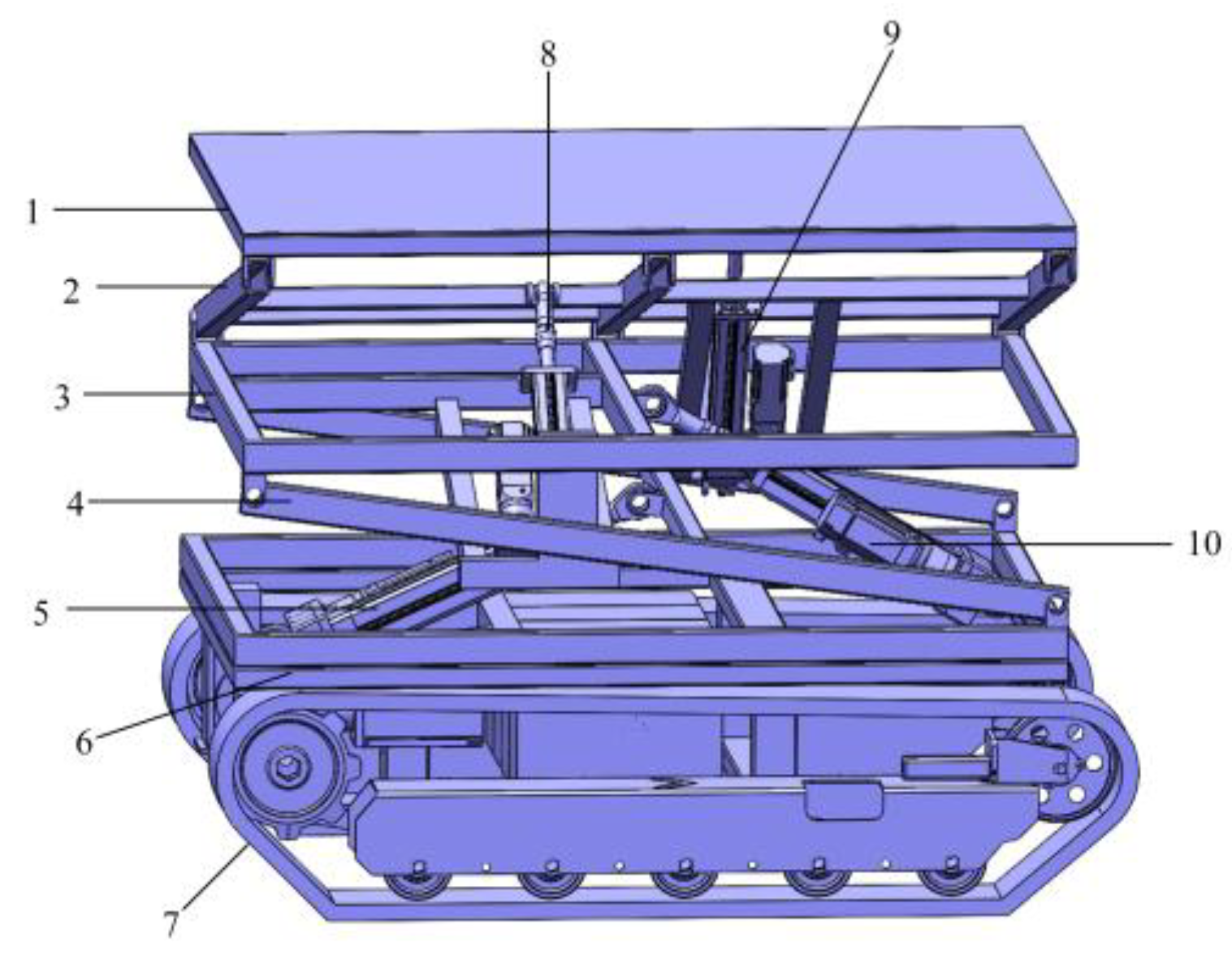
Figure 1. Omnidirectional levelling system: Schematic diagram of structure levelling of crawler machine. 1. Superstructure Frame 2. Upper Support Frame 3. Intermediate Frame 4. Lower Support Frame 5. Rear Longitudinal Leveling Servo-Electric Cylinder 6. Chassis Frame 7. Tracked Undercarriage 8. Right Lateral Leveling Servo-Electric Cylinder 9. Left Lateral Leveling Servo-Electric Cylinder 10. Front Longitudinal Leveling Servo-Electric Cylinder.
Agriculture 15 01920 g001
Figure 2. Static model of caterpillar farm machine chassis.
Agriculture 15 01920 g002
Figure 3. Mathematical Model for Longitudinal Rollover of Tracked Agricultural Machinery Chassis.
Agriculture 15 01920 g003
Figure 4. Mathematical Model for Lateral Rollover of Tracked Agricultural Machinery Chassis.
Agriculture 15 01920 g004
Figure 5. Variation of rollover Angle for the Crawler Agricultural Chassis under Loading Conditions.
Agriculture 15 01920 g005
Figure 6. Superstructure Frame Model of Tracked Agricultural Machinery Chassis.
Agriculture 15 01920 g006
Figure 7. Chassis Model of Tracked Agricultural Machinery Chassis.
Agriculture 15 01920 g007
Figure 8. Servo-Electric Cylinder Model of Tracked Agricultural Machinery Chassis.
Agriculture 15 01920 g008
Figure 9. Virtual Prototype Model of Tracked Agricultural Machinery Chassis.
Agriculture 15 01920 g009
Figure 10. Pavement model.
Agriculture 15 01920 g010
Figure 11. Ball screw rotation-linear motion model.
Agriculture 15 01920 g011
Figure 12. Ball screw linear-linear motion model.
Agriculture 15 01920 g012
Figure 13. Sliding mode control system block diagram.
Agriculture 15 01920 g013
Figure 14. Simulation of longitudinal 25° slope of crawler machine.
Agriculture 15 01920 g014
Figure 15. Running performance of caterpillar machine on slope pavement.
Agriculture 15 01920 g015
Figure 16. Simulation of the horizontal 20° slope of the crawler operator.
Agriculture 15 01920 g016
Figure 17. Driving performance of crawler machine on cross slope road surface.
Agriculture 15 01920 g017
Figure 18. Simulation diagram of crawler agricultural machine chassis all direction leveling.
Agriculture 15 01920 g018
Figure 19. All-directional levelling performance of crawler machine.
Agriculture 15 01920 g019
Figure 20. Crawler machine loading condition simulation diagram.
Agriculture 15 01920 g020
Figure 21. Levelling performance of crawler machine under loading conditions.
Agriculture 15 01920 g021
Figure 22. Servo-Electric cylinder model.
Agriculture 15 01920 g022
Figure 23. AMEsim co-simulation model.
Agriculture 15 01920 g023
Figure 24. Mechanical and electrical joint simulation model of crawler machine.
Agriculture 15 01920 g024
Figure 25. Comparison of the levelling performance of crawler machine.
Agriculture 15 01920 g025
Figure 26. Prototype and related equipment.
Agriculture 15 01920 g026
Figure 27. Static test site.
Agriculture 15 01920 g027
Figure 28. Static leveling test Angle change and leveling speed diagram.
Agriculture 15 01920 g028
Figure 29. Test of the whole machine.
Agriculture 15 01920 g029
Figure 30. Horizontal dynamic performance test of the whole machine.
Agriculture 15 01920 g030
Figure 31. The whole machine dynamic performance test.
Agriculture 15 01920 g031
Figure 32. Angle variation diagram of omni-directional leveling dynamic test.
Agriculture 15 01920 g032
Table 1. Longitudinal tilt Angle of crawler machine.
Longitudinal Static Rollover AngleLongitudinal Leveling Rollover Angle
38.9°42.9°
Table 2. Lateral tilt Angle of crawler machine.
Lateral Static Rollover AngleLateral Leveling Rollover Angle
31.2°38.3°
Disclaimer/Publisher’s Note: The statements, opinions and data contained in all publications are solely those of the individual author(s) and contributor(s) and not of MDPI and/or the editor(s). MDPI and/or the editor(s) disclaim responsibility for any injury to people or property resulting from any ideas, methods, instructions or products referred to in the content.