Abstract
To address the problems of incomplete coverage of complex plots and low efficiency in unmanned agricultural machinery operations, the study proposes the Human–Machine Collaboration (HMC). Targeting different types of plots, the study designed the method of area division based on the Breseham algorithm and the polygonal clipping algorithm. In addition, the study proposed a secondary division method of the area based on alternating point judgment and risk area evaluation function to ensure the security of the HMC. The experimental results show that the coverage rate of HMC is 100% and the field operation work efficiency is higher than 86% under different shapes of plots (rectangle, right trapezoid and ordinary quadrilateral). In the three shapes of plots, the operation scores of the HMC in the open edge area are 96.08, 163.39, and 137.4, respectively; the operation scores in other areas are 104.73, 89.88, 97.77, respectively; and the comprehensive scores are 162.36, 204.33, and 189.85, respectively, which are higher than those of unmanned operation and manned operation, showing comparatively better performance. The area division under the HMC meets the operational requirements, and the research provides technical support for unmanned farm development.
1. Introduction
In order to alleviate the shortage of agricultural labor and improve agricultural productivity, an unmanned farm with full process and all-weather is an important development direction for future agriculture. Agricultural equipment cooperative operation technology is one of the keys to unmanned farms. In recent years, researchers have carried out more studies on multi-machine cooperative operation technology for agricultural machines, including a master–slave robot system [1,2,3,4,5], agricultural machinery automatic following system [6], rice harvesting and forwarding dual-machine cooperative operation strategy [7], multi machine collaborative navigation service platform for agricultural machinery [8,9], multi-dimensional multi-machine cooperative technology research for agricultural machines [10], and dual-unloading mode autonomous operation strategy and co-transporter system for rice harvester and transporter [11], which have achieved rich research results.
However, paddy fields have various shapes, among which rectangles, trapezoids and ordinary quadrilaterals account for the largest proportion of paddy fields in southern China [12]. In complex-shaped plots, it is difficult for unmanned agricultural machines to achieve full field coverage [13], and manned operation is still needed to supplement and complete operations in some complex areas [14,15]. The Human–Machine Collaboration (HMC) of agricultural machinery operation is a work mode that emphasizes the coordination and cooperation between unmanned and manned driving agricultural machinery in field operations to jointly complete specific operation tasks. Through this cooperation mode, it can effectively avoid agricultural machinery collision and waste of resources.
At present, there is a lack of effective working area division methods in the HMC of unmanned agricultural machinery [14,16]. Only reasonable HMC area division can realize more flexible, efficient and orderly operation of agricultural machinery in different shapes of plots, so as to ensure full field coverage. In this paper, we will analyze the HMC according to the characteristics of farmland and operational requirements, establish a work area division system under the HMC, visualize the real-time display of agricultural machinery and operational information under the HMC, provide decision-making on the area division method and support for the software platform for multiple agricultural machines under the HMC according to different operational scenarios, and conduct field tests on the HMC area division method for rice harvesters with different shapes of plots to verify the applicability and adaptability of the working area division method under the HMC for rice harvesters.
2. Design of Region Segmentation Method in Human–Machine Cooperative Mode
In this section, the area division function module, the HMC area division algorithm, the alternative point design for the HMC, and the risk area delineation are described in detail.
2.1. Design of Function Modules for Area Division
Area division is the fundamental aspect of determining the quality and safety of the HMC. The design of the area division function module is shown in Figure 1. The area division includes three parts: the first area division, the path division and the secondary division. The first division uses the contour extraction method to judge the type of the plot and realize the polygonal shape mark. Then, according to the labeling results, the improved Breseham traversal method is used to achieve the width inward shrinkage to ascertain the unmanned area, and at the same time, the edge area is determined to be the open-edge or closed-edge area for artificial driving. Using the collected information of the set of boundary points and the set of points within the boundary, polygonal clipping is carried out to achieve the first area division. After completing the first area division, the path segmentation is performed based on the imported path planning route and the calculated area division data results [17,18,19,20]. The planned path in the unmanned area is intercepted and imported as the unmanned area operation path, which is used as the operation path of the automatic navigation system for unmanned agricultural machines. In order to ensure the safety factors, the secondary division is executed. The alternative point according to the width of the maned driving region is used to calculate the distance parameter, which is used to deviate the alternative point from the unmanned area boundary of a certain width. Alternative points are selected in the part where the boundary to the unmanned area is in safety distance, so as to maximize the protection of the unmanned operation and avoid interference with the unmanned area. When the degree of inclination and curvature of the oblique angle of the land parcel exceeds a certain threshold, it will increase the riskiness of unmanned operation, so a threshold screening of the degree of inclination and curvature of the oblique angle is adopted, and excessive risk area is marked.
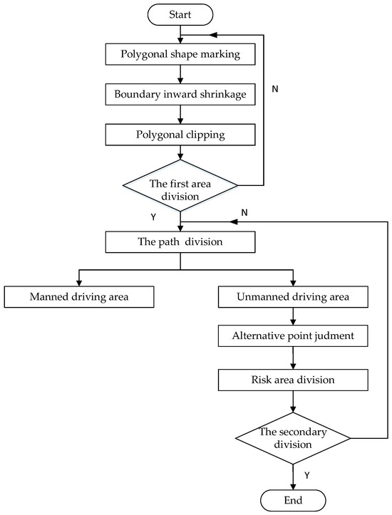
Figure 1.
Design flowchart of area division module for HMC.
2.2. Human–Machine Cooperative Area Division Algorithm
The problem to be solved by the HMC area division algorithm is how to find out the range of unmanned and manned driving areas under the HMC, and reasonably control the range of area division to reduce the risk of marginal operation of unmanned agricultural machines while ensuring the maximization of operational efficiency [21]. In the unmanned farm with the same piece of unmanned and manned driving agricultural machine cooperative operation application scenarios, the HMC area division algorithm needs to be based on the shape of the plot of land to divide area in general.
The area division algorithm calculates the imported farmland into a planar geometric figure, and determines the shape in the area and solves the area division range by the width inward shrinkage. The combination of Breseham algorithm [22,23] and polygonal clipping algorithm can well achieve this calculation step. As the shape of the farmland is variable, it is necessary to adjust the value of the internal shrinkage according to the different terrain and the area division needs to be classified into two kinds of areas: unmanned driving and manned driving. Considering the variable shape of farmland, the Breseham algorithm is optimized and expanded to meet the requirements of different terrains and operations. Based on the original Breseham algorithm, as shown in Figure 2, a geometric calculation method is introduced to calculate the starting angle information of the e-th edge, thereby determining the shape judgment parameter for the corresponding edge.
where is the shape judgment parameter of the e-th edge (value range [0, 2]), and the greater the value, the greater the angle between the two ends of the edge and the right angle deviation, and the higher the shape irregularity; is the internal angle of the vertex at the starting point of the e-th edge, which is also the angle between the two adjacent sides at the vertex; is the internal angle of the endpoint vertex of the e-th edge; After traversing the boundary points, the point-by-point inward shrinkage calculation method is introduced to achieve the adaptive inward shrinkage of different shapes of field. When the coordinates of the point of change are , its unit normal vector pointing to the interior of the parcel is , the width of the agricultural machine is ω; the result of the shape judgment is which is determined by . When < 0.2, the included angle at both ends of the edge is close to the right angle (regular edge), and the corresponding shrinkage coefficient ; when 0.2 < ≤ 0.5, the included angle at both ends of the edge moderately deviates from the right angle (moderately irregular edge), and the corresponding shrinkage coefficient ; when > 0.5, the included angle at both ends of the edge severely deviates from the straight angle (highly irregular edge), and the corresponding shrinkage coefficient = 3.
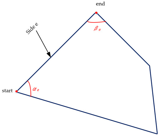
Figure 2.
Diagram illustrating the calculation of the shape determination parameter .
According to the result of the shape judgment, the distance of inward shrinkage of the normal vector is . Hence, the coordinates of point-by-point after the inward shrinkage are
The method for inward shrinkage of plots boundary with different shape fields is shown in Figure 3.

Figure 3.
Schematic diagram of boundary inward shrinkage of plots boundary with different shape fields (a) inward boundary shrinkage of rectangular plot; (b) inward boundary shrinkage of right trapezoid plot; (c) inward boundary shrinkage of ordinary quadrilateral plot.
After calculating the boundary values of the two area types, a polygonal clipping algorithm is introduced to save the area division results, which provides the basis for path division.
During the process of the HMC, it is important to ensure that unmanned and manned driving agricultural machines operate according to the designated path planning in respective areas. The unmanned farm machine operates in the unmanned area according to the specified path planning, while the manned driving farm machine operates in the manned driving region guided by the standard path planning. Therefore, it is necessary to divide the known path planning after the division of the HMC area into unmanned path planning and manned driving path planning. Known path information is obtained according to the platform, which includes a trajectory of the farm machine in the farmland, an extent of the operation area, and associated geographic coordinates. By means of the path information packet, a start point and a termination point of the unmanned path are determined.
The path information is analyzed according to the set operation mode criteria. If the mode of operation is unmanned operation first and then manned driving along the edge of the farmland, the unmanned path cutting in the path cutting is reduced by one width of the agricultural machine to prevent repetitive milling. The starting and ending points of the automatic harvesting operation path coincide and are positioned as close as possible to the field entrance to minimize the transport path length. is the starting point of the unmanned path in the original path information, is the ending point of the unmanned path in the original path information, represents the width of the agricultural machine. Then, the start point of unmanned path is
The termination point of the driverless path is
If the operation mode is manned driving first and then unmanned driving, the manned driving area in the path cutting has an extra width distance to prevent the operation task from being missed. is the starting point of the unmanned path in the original path information, is the ending point of the unmanned path in the original path information. Then, the starting point of unmanned path is
The ending point of the driverless path is
In the process of path division, the safety factors of farmland operation are comprehensively considered to ensure that no conflict or danger occurs during the switching process in alternative areas. Simultaneously, the task-completion degree of the operation is considered to ensure that when switching between different operation modes, both unmanned and manned driving agricultural machines can efficiently complete their respective operation tasks.
The planned paths are cut into unmanned control paths and manned guidance paths according to the scope of area division. After the completion of this calculation step, in order to further ensure the cooperation coherence and safety of the HMC, the calculation of the HMC alternative points and the division of the risk area are completed based on the operating parameters of the agricultural machinery and the results of the area division.
The aforementioned HMC area division algorithm is shown in Figure 4.
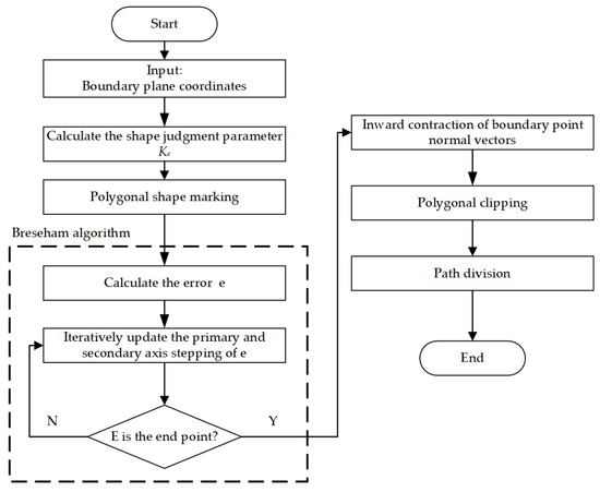
Figure 4.
Algorithm flowchart of HMC area division algorithm.
2.3. Human–Machine Cooperative Operation Alternative Point Setting
In order to ensure smooth transition and efficient alternation between unmanned and manned driving agricultural machines in cooperative operation, and reduce the path crushing situation. Setting of alternative points is carried out after the path division, and the alternative points are selected in the part from the boundary of the manned driving area to the boundary of the unmanned area, which protects the operation area of the unmanned agricultural machine from interference [24]. Calculate the distance parameters of the manned driving area, and the alternative point is deviated from the boundary of the unmanned area by a certain width, which ensure efficient alternation between unmanned and manned driving agricultural machines. To reduce the rate of repeated crushing, curves or turns were avoided when selecting the alternative point. The static alternative point location, , was determined by introducing the turning factor:
where is the alternative point position vector; is the path division boundary point position vector; is the distance parameter calculated according to width of the manned driving area; is the agricultural machine operation width; is the path division boundary point normal vector; T is the turning factor parameter, which is determined by the control point of the unmanned agricultural machinery. This parameter relates to the length and turning radius of the machinery; is the boundary point tangent vector. The setting of static alternative points realizes the efficient connection between manned driving and unmanned agricultural machines, ensures the smooth operation process, and maximizes the protection of the operation area of unmanned agricultural machines.
2.4. Risk Area Division
As shown in Figure 5, when there is a potentially hazardous area in the operation plot that affects the operation quality and operation safety, it needs to be predicted. Additionally, when the risk value is excessive, an agricultural machinery driver should be reminded to substitute operation in time, which ensures that it can operate smoothly in the oblique angle or curved edge risk area. Hence, it is necessary to divide the region into risk areas.
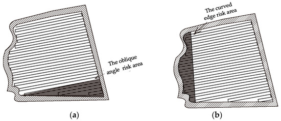
Figure 5.
Schematic diagram of the HMC risk areas. (a) The oblique angle risk area; (b) The curved edge risk area.
When an oblique angle in the unmanned area exceeds the set threshold range , it is defined as the oblique angle risk area. The oblique angle risk area indicates the presence of a steeper oblique angle in the area, leading to an unstable or dangerous situation for the agricultural machine during operation. Similarly, a curved edge risk area is defined when the curvature of the curved edge exceeds the set threshold range . The curved edge risk area indicates that the boundary lines of the farmland areas are more curved, making it impossible for the farm machine to maintain a stable trajectory while passing through these areas. The value range of and is from 0.6 to 0.8, and the specific value is related to soil moisture, hard strata and so on. In this test, and are all set 0.6.
The coordinates of the two points in the hypotenuse, , are (, ) and (, ). The oblique angle risk area is judged to be
If , classify the area as the oblique angle risk area.
Use mathematical modeling methods to calculate curvature metrics for curves and calculate tangent and normal vectors for curves:
Calculate the modulus of the tangent vector and the modulus of the normal vector:
Calculating curvature :
If , the area is classified as the curved edge risk area. Areas of farmland with steeper oblique angle and curved edge are identified and labeled. This risk division provides important information about the topography and boundaries of the farmland, and better represents the characteristics and potential risks of the farmland.
The Breseham algorithm is imported into the risk area division to traverse the two-point coordinates of the hypotenuse or the set of points of the curved edge coordinates, and the mathematical model is used to calculate the oblique angle (θ) of the hypotenuse and the curvature () of the curved edge, which indicate the degree of steepness and curvature of the parcel boundary. The θ and are compared with the preset risk value, respectively. If any parameter exceeds the risk value, the area is marked as the risk area. The polygonal clipping algorithm is used to divide the risk area, and flag bits and division information are transmitted to the automatic navigation system. The agricultural machinery driver also can receive the visual reminders. When the operation risk is too high, the driver should carry out supplementary operation in time to ensure the safety of the HMC.
3. Experimental Design and Analysis
In this chapter, the experimental system and equipment, the HMC experimental design of the rice harvester, and the experimental results and analysis will be discussed.
3.1. Testing Systems and Equipment
The overall structure of the proposed work area division system in the HMC is shown in Figure 6. In the structure of the HMC area division system, the cloud platform transmits the command information to the vehicle-mounted screen control system of multiple agricultural machinery, which include manned driving and unmanned driving machinery. In this paper, we took the HMC of two agricultural machines as an example. Manned driving agricultural machine equipped with manned driving vehicle screen control system, through using the manual end of the algorithm of HMC area division, the operation of dynamic visualization, the HMC and risk warning function is achieved, which effectively assists the agricultural driver to complete the driving task.
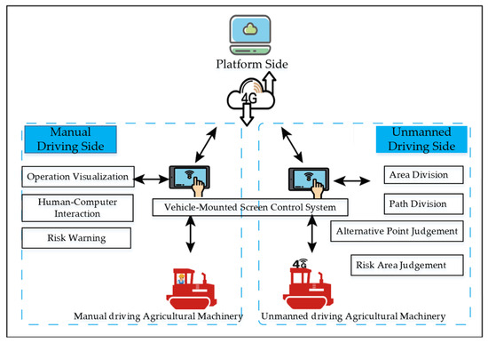
Figure 6.
Schematic diagram of the operation area division system under the HMC.
Harvester human–machine cooperation system includes tracked unmanned rice harvester (Yanmar YH1180 tracked grain combine harvester) and tracked manned driving rice harvester (Yanmar YH1180 tracked grain combine harvester), equipped with a fully electronically controlled chassis and an automatic navigation system, which can realize the HMC process of the unmanned agricultural machine’s automatic operation and the manned driving agricultural machine’s screen control system communication and visualization. The positioning system adopts the display and control integrated screen tablet, which contains the functions of display, control, storage, positioning and so on. It adopts the display and control integrated SPRING10 type II fastening vehicle mounted tablet produced by Shenzhen Congping Technology Co., Ltd. (Zhiheng Industrial Park, No.15, Guankou Second Road, Anle community, Nantou street, Nanshan District, Shenzhen, China), which is equipped with the Android 6.0.1 version system and can meet the use of the HMC. The software part is developed by Android studio. The HMC test vehicle is shown in Figure 7. The main structural parameters of Yangma YH1180 tracked grain combine harvester is shown in Table 1, and the cutting width in the test is 2.05 m.
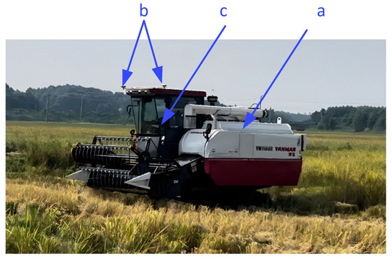
Figure 7.
Physical drawing of the harvester. (a) Harvester; (b) RTK-GNSS positioning system; (c) In-car screen control system.

Table 1.
Main structural parameters of Yangma YH1180 tracked grain combine harvester.
3.2. Experimental Design of Human–Machine Collaboration for RICE Harvester
(1) Experimental methods
In order to verify the effectiveness of the proposed HMC area division method, this study carried out harvest operation experiments in a dry field environment. The experiment was carried out using a harvester (Figure 7) in three different shaped plots (Figure 8b), including rectangular N1, right trapezoid N2, and ordinary trapezoid N3. The plots image information was collected by DJI Mavic 3T (Figure 8a), and the operation data were acquired in real time through RTK-GNSS and the HMC system. The experimental site is located at the Zengcheng Experimental Base of South China Agricultural University, Guangzhou, China.
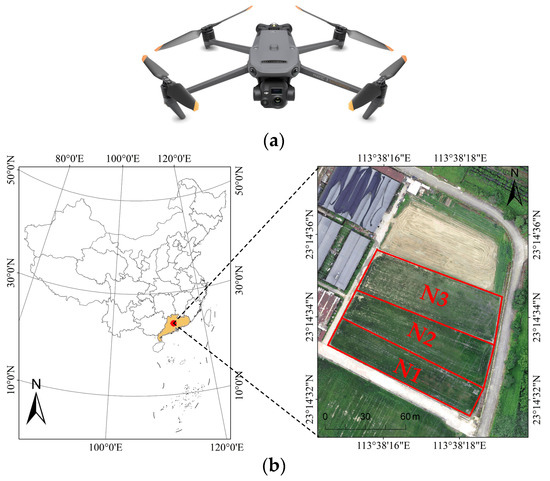
Figure 8.
Plots image information acquisition platform and experimental scene. (a) DJI Mavic 3T; (b) Experimental scene. (Rectangle plot, right trapezoid and ordinary quadrilateral plot are named as N1, N2, and N3, respectively.).
Three operation modes (HMC, unmanned operation, and manual operation) and three shape plots (N1, N2, and N3) were set up in the experiment. By systematically comparing the harvest performance under different operation scenarios, the adaptability and performance differences in each operation mode for different shape plots were comprehensively analyzed.
The schematic diagram of the HMC area division test is shown in Figure 9. After the cloud platform releases the operation instruction at the beginning of the trial, the unmanned agricultural machine end resolves the target plot and operation mode, and the unmanned agricultural machine port resolves the operation instruction and completes the area division of the target plot to start the operation. It also transmits the division data to the end of manned driving farm machine to realize the dynamic visualization display and complete the rice harvesting operation with the HMC.
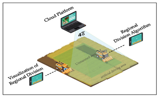
Figure 9.
Schematic diagram of the HMC area division test.
(2) Performance indicators
In order to comprehensively evaluate the comprehensive performance of the HMC area division method, the harvest operation area is divided into an open edge operation area and the rest of the operation area. The following quantitative metrics are introduced:
- ①
- Field operation coverage is ρ, Linear operation coverage area is , which are calculated as follows:where is the total length of the linear operation; is the width of machine tool; is the total area of the farmland area.
- ②
- The field operation work efficiency is η, the total turn path length is , which are calculated as follows:where M is the total number of turns; and is the shortest turn path length.
- ③
- The evaluation score of field open edge work is which is calculated as follows:where is the area of the open edge operation; is the time of the open edge operation; and is the coverage of the operation.
- ④
- The operation score of remaining areas is which is calculated as follows:where is the area of operation in the remaining area; is the time of operation in the remaining area; and is the operational coverage.
- ⑤
- The overall performance score is which is calculated as follows:where R is a risk mitigation parameter, which considers whether different operational modes effectively reduced the potential risks, and the larger the value of R is, the stronger the ability to reduce potential risks, and the value of R is in the range of [0, 1]; α, β, γ and δ are weight parameters, which are used for balancing the relative importance of different indexes, and the value of them is in the range of [0, 1].
3.3. Experimental Results and Analysis
In the rice harvester HMC test, the unmanned harvester and the manned driving harvester completed the HMC process according to the predetermined area and path division, and the operation trajectory and area division were shown in Figure 10. Three groups of tests were carried out including rectangle, right trapezoid and ordinary quadrilateral.

Figure 10.
Plot zoning trajectory map. (a) Rectangular zoning trajectory; (b) Right trapezoid zoning trajectory; (c) Ordinary quadrilateral zoning trajectory.
The results are shown in Table 2, which shows that the coverage rate reach to 100%, field operation work efficiency of the HMC in the rectangle, right trapezoid, ordinary quadrilateral operation reaches are 88.73%, 87.18%, 86.77%, respectively. The reason for this result is that the more complex the boundary shape, the longer the turning path, and the lower the field operation work efficiency.

Table 2.
The HMC area division test results. (Keep two decimal places).
The work efficiency is higher than the average work efficiency of rice harvesting production and improves production efficiency. The coverage rate reaches to 100%, which meets the production requirements. In terms of operation coverage area and work efficiency index, it is better than the convex polygon operation path planning method proposed in the literature [25].
Comparison of various indicators of the HMC with traditional fully manned and unmanned operations for plots from N1 to N3 are shown in Table 3, Table 4 and Table 5, respectively.

Table 3.
Comparison of experimental results of the HMC, manned operation and the unmanned operations in rectangular plots.

Table 4.
Comparison of experimental results of the HMC, manned operation and the unmanned operations in right trapezoid plots.

Table 5.
Comparison of experimental results of the HMC manned operation and the unmanned operations in ordinary quadrilateral plots.
As shown in Table 3, Table 4 and Table 5, the average score of edging operation in the HMC is lower than that of the traditional all-manual by 0.01, while is higher than that of the unmanned operation by 21.88 on average. It is concluded that in the edge-opening operation the HMC area has effectively played the maneuverability and high efficiency of the manned driving, and avoided the inefficiency of unmanned operations; the average score of the remaining area operation in the HMC is higher than that of the traditional fully manned and the unmanned operation by 14.29 and 10.44, respectively. Due to the introduction of the open edge by the manned driving operation, the coverage rate reaches 100%. It is concluded that the HMC plays the advantage of high efficiency of the unmanned operation in the remaining area, and also makes up its deficiency of the unmanned operation that cannot realize the full coverage; The average score of the comprehensive performance in the HMC is higher than that of the traditional fully manned and the unmanned operation by 11.06 and 31.24, respectively. Hence, the experimental results demonstrate that the HMC area division operation mode effectively improves the operation productivity and anti-risk capability.
4. Conclusions
This study proposed a novel human–machine cooperative (HMC) area division method for intelligent agricultural machinery, addressing challenges such as incomplete coverage in complex plots and low operational efficiency. By integrating shape identification algorithms, adaptive boundary shrinkage, and risk-aware secondary division, the method achieved 100% coverage and significantly improved operational efficiency. Field tests demonstrated that the HMC mode outperformed traditional manned and fully unmanned operations, with comprehensive performance scores surpassing both unmanned and manned operations in rectangular, right trapezoid and quadrilateral plots. Key results include field work efficiencies of 88.73% (rectangle), 87.18% (right trapezoid), and 86.77% (ordinary quadrilateral), along with superior operational scores in edge (96.08–163.39) and non-edge areas (89.88–104.73). Future studies should validate the method in larger or irregular plots and address scalability (beyond two machines), real-time optimization, and multi-season validation to enhance robustness and practical applicability.
Author Contributions
Conceptualization, J.H. (Jie He) and R.Z.; methodology, J.Z., J.H. (Jing He) and R.Z.; software, J.H. (Jing He), J.Z. and R.Z.; validation, R.Z. and Z.C.; data curation, J.H. (Jiatao Huang), J.Z., G.W. and R.Z.; writing—original draft preparation, J.H. (Jing He) and J.Z.; writing—review and editing, J.H. (Jing He)and R.Z.; project administration, J.H. (Jie He); funding acquisition, G.W. and J.H. (Jie He). All authors have read and agreed to the published version of the manuscript.
Funding
This work was supported by the Jiangxi Provincial Science and Technology Special Project of Jinggangshan Agricultural High-tech Zone (No. 20222-051252), the Characteristic Innovation Projects of Ordinary Universities in Guangdong Province (No. 2024KTSCX398) and the Guangdong Polytechnic of Industry and Commerce Scientific Research Project (No. 2023-gc-04).
Data Availability Statement
The data will be made available upon reasonable request by the corresponding author.
Acknowledgments
The authors would like to express their gratitude to the Guangdong Polytechnic of Industry and Commerce, the Key Laboratory of the Ministry of Education of China for Key Technologies for Agricultural Machinery, the Guangdong Provincial Key Laboratory for Agricultural Artificial Intelligence, and Equipment for Southern China, and the reviewers who provided helpful suggestions for this manuscript.
Conflicts of Interest
Author Guoqing Wang was employed by the company Ji’an City Crop Breeding Farm. The remaining authors declare that the research was conducted in the absence of any commercial or financial relationships that could be construed as a potential conflict of interest.
References
- Noguchi, N.; Will, J.; Reid, J.; Zhang, Q. Development of a master slave robot system for farm operations. Comput. Electron. Agric. 2004, 44, 1–19. [Google Scholar] [CrossRef]
- Zhang, C.; Noguchi, N.; Yang, L. Leader-follower system using two robot tractors to improve work efficiency. Comput. Electron. Agric. 2016, 121, 269–281. [Google Scholar] [CrossRef]
- Zhang, X.; Geimer, M.; Noack, P.; Grandl, L. A semi-autonomous tractor in an intelligent master-slave vehicle system. Intell. Serv. Robot. 2010, 3, 263–269. [Google Scholar] [CrossRef]
- Bai, X.; Wang, Z.; Hu, J.; Gao, L.; Xiong, F. Harvester group corporative navigation method based on leader-follower structure. Trans. Chin. Soc. Agric. Eng. 2017, 48, 14–21. [Google Scholar]
- Iida, M.; Kudou, M.; Ono, K.; Umeda, M. Automatic following control for agricultural vehicle. In Proceedings of the 6th International Workshop on Advanced Motion Control, Istanbul, Turkey, 30 March–1 April 2000; pp. 158–162. [Google Scholar]
- Zhang, W.; Zhang, Z.; Zhang, F.; Ding, F.; Hu, L.; Luo, X. Cooperative autonomous operation strategy and experiment of the rice harvester together with a rice-transporting vehicle. Trans. Chin. Soc. Agric. Eng. 2021, 37, 11. [Google Scholar]
- Zhang, F.; Zhang, W.; Luo, X.; Zhang, Z.; Lu, Y.; Wang, B. Developing an IoT-Enabled Cloud Management Platform for Agricultural Machinery Equipped with Automatic Navigation Systems. Agriculture 2022, 12, 310. [Google Scholar] [CrossRef]
- Li, H.; Zhong, T.; Zhang, K.; Wan, Y.; Zhang, M. Design of Agricultual Machinery Multi-machine Cooperative Navigation Service Platform Based on WebGIS. Trans. Chin. Soc. Agric. Eng. 2022, 53 (Suppl. S1), 28–35. [Google Scholar]
- Wang, B.; Mao, H.; Wang, Y.; Pan, S. Influencing Factors and Mechanism of Multi-dimensional Agricultural Machinery Collaborative Technologies Adoption. Trans. Chin. Soc. Agric. Eng. 2023, 54, 45–53. [Google Scholar]
- Ding, F.; Luo, X.; Zhang, Z.; Hu, L.; Wu, X.; Bao, K.; Zhang, J.; Yuan, B.; Zhang, W. Dual-Unloading Mode Autonomous Operation Strategy and Cotransporter System for Rice Harvester and Transporter. Engineering 2025, 48, 220–233. [Google Scholar] [CrossRef]
- Oksanen, T.; Visala, A. Coverage path planning algorithms for agricultural field machines. J. Field Robot. 2009, 26, 651–668. [Google Scholar] [CrossRef]
- Rahman, K.N.N. Optimum harvesting area of convex and concave polygon field for path planning of robot combine harvester. Intell. Serv. Robot. 2019, 12, 167–179. [Google Scholar] [CrossRef]
- Jeon, C.W.; Kim, H.J.; Yun, C.; Han, X.; Kim, J.H. Design and validation testing of a complete paddy field-coverage path planner for a fully autonomous tillage tractor. Biosyst. Eng. 2021, 208, 79–97. [Google Scholar] [CrossRef]
- Zhao, J.; Fan, S.; Zhang, B.; Wang, A.; Zhang, L.; Zhu, Q. Research Status and Development Trends of Deep Reinforcement Learning in the Intelligent Transformation of Agricultural Machinery. Agriculture 2025, 15, 1223. [Google Scholar] [CrossRef]
- Wang, B.; Du, X.; Wang, Y.; Mao, H. Multi-machine collaboration realization conditions and precise and efficient production mode of intelligent agricultural machinery. Int. J. Agric. Biol. Eng. 2024, 7, 27–36. [Google Scholar] [CrossRef]
- Gupta, M.; Abdelsalam, M.; Khorsandroo, S.; Mittal, S. Security and Privacy in Smart Farming: Challenges and Opportunities. IEEE Access 2020, 8, 34564–34584. [Google Scholar] [CrossRef]
- Hameed, I.A.; Bochtis, D.D.; Sorensen, C.G. Driving angle and track sequence optimization for operational path planning using genetic algorithms. Appl. Eng. Agric. 2011, 27, 1077–1086. [Google Scholar] [CrossRef]
- Jin, J.; Tang, L. Optimal coverage path planning for arable farming on 2D surfaces. Trans. Asabe 2010, 53, 283–295. [Google Scholar] [CrossRef]
- Spekken, M.; de Bruin, S. Optimized routing on agricultural fields by minimizing maneuvering and servicing time. Precis. Agric. 2013, 14, 224–244. [Google Scholar] [CrossRef]
- Yao, J.; Teng, G.; Huo, L.; Yuan, Y.; Zhang, F. Optimization of cooperative operation path for multiple combine harvesters without conflict. Trans. Chin. Soc. Agric. Eng. 2019, 35, 7. [Google Scholar]
- Zhao, B.; Zhang, W.; Yuan, Y.; Wang, F.Z.; Zhou, L.M.; Niu, K. Research Progress in information Technology for Agricultural Equipment Maintenance and Operation Serive Management. Trans. Chin. Soc. Agric. Eng. 2023, 54, 1–26. [Google Scholar]
- Nie, Z.; Cao, J.; Weng, N. Convolutional Hough Line Segment Detection Based on Line Generation. Comput. Technol. Dev. 2024, 34, 30–36. [Google Scholar]
- Velikzhanin, A.; Skarga-Bandurova, I. A Bresenham-based Global Path Planning Algorithm on Grid Maps. In Proceedings of the 2023 International Conference on Dependable Systems, Services and Technologies, Athens, Greece, 13–15 October 2023. [Google Scholar]
- Zhang, M.; Ji, Y.; Li, S.; Cao, R.; Xu, H.; Zhang, Z. Research Progress of Agricultural Machinery Navigation Technology. Trans. Chin. Soc. Agric. Eng. 2020, 51, 1–18. [Google Scholar]
- Huang, X.; Zhang, L.; Wang, S.; Luo, C. Path Planning of Rapeseed Combine Seeder in Field of Convex Boundary. Trans. Chin. Soc. Agric. Mach. 2022, 53, 33–40. [Google Scholar]
Disclaimer/Publisher’s Note: The statements, opinions and data contained in all publications are solely those of the individual author(s) and contributor(s) and not of MDPI and/or the editor(s). MDPI and/or the editor(s) disclaim responsibility for any injury to people or property resulting from any ideas, methods, instructions or products referred to in the content. |
© 2025 by the authors. Licensee MDPI, Basel, Switzerland. This article is an open access article distributed under the terms and conditions of the Creative Commons Attribution (CC BY) license (https://creativecommons.org/licenses/by/4.0/).