1. Introduction
Facility horticulture is an important component of modern agriculture and plays a significant role in ensuring agricultural product supply [
1,
2]. As of recent data, the total area of facility horticulture in China reaches approximately 3.7 million hectares, accounting for nearly 80% of the global facility horticulture area [
3]. After an extended period of development, agricultural facilities have established structural types that are suitable for the local climate in various production regions [
4,
5]. The structural safety of greenhouses is a prerequisite for ensuring normal production. However, plastic greenhouses are often designed with a low safety margin [
6]. Many researchers have investigated the stability of greenhouse structures under various load conditions using experimental and numerical methods. For example, the study by Castellano et al. [
7] carried out a full-scale load test of a double sloping roof greenhouse and a pitched roof greenhouse structure, focusing on the influence of wind and snow loads on their bearing capacity. Briassoulis et al. [
8] developed a three-dimensional structural model of a large multi-span circular greenhouse, as well as a two-positioned frame model, utilizing linear, geometric, and material nonlinear analysis methods to investigate the greenhouse’s failure modes under wind and snow loads. Additionally, Wang et al. [
9,
10] used ANSYS software to analyze the static and dynamic responses and failure mechanisms of the single-tube and truss-type structures of a prefabricated ground-mounted solar greenhouse. These studies provide valuable references for the stability of greenhouse structures under various loads.
The large-span insulated plastic greenhouse is characterized by its large span and spacious interior, which enhances land utilization efficiency and ensures environmental stability [
11,
12], demonstrating significant application potential [
13,
14]. It has gained widespread recognition in the Yellow-Huai River Basin region of China. Compared with the conventional plastic greenhouses, the large-span insulated plastic greenhouse has a larger span and more complex structure, thus demanding higher standards for structural safety [
15]. Several studies have been conducted on the static and dynamic load-bearing mechanisms of large-span insulated plastic greenhouses. Ren et al. [
16] performed a structural analysis on a large-span plastic greenhouse that combines flat truss arches and spatial truss arches, analyzing the structural behavior under stress, deformation, and instability. The results indicate that structural safety was primarily governed by the strength and stiffness of the components. Wang et al. [
17] examined the load-bearing characteristics and dynamic behavior of large-span plastic greenhouses with single-tube structures using static analysis and time history methods. The research found that such structures are more sensitive to non-uniformly distributed snow loads, with the time history analysis revealing a significant increase in maximum displacement and bending stress. However, these studies typically treat the configuration of the tie rod and ridge height as constant factors. The significance of tie rod configuration and ridge height for greenhouse load-bearing performance and structural stability has been overlooked. Thus, further research is needed on the load-bearing characteristics of the frame structures of large-span insulated plastic greenhouses.
In this research, three structures for a large-span insulated plastic greenhouse were designed. Finite element models of the 3-D frame structure were developed using ANSYS Workbench 2022. Three greenhouse structures were calculated under seven load actions, in accordance with the relevant design codes. The stress and deformation characteristics were analyzed. The most unfavorable load combination was identified. Then, under the most unfavorable load action, the instability mechanisms and ultimate bearing capacities of the three structures under double nonlinear conditions were further investigated. The load-bearing capacities of the three structures were evaluated, and the superior structure was chosen. Based on the chosen structure, 3-D models of large-span insulated plastic greenhouse structures with varying ridge heights were established. The ultimate bearing capacities were analyzed under the most unfavorable load combination. The research results can clearly determine the impact of tie rod configuration and ridge height on the load-bearing capacity of large-span insulated plastic greenhouses.
3. Results
3.1. Deformation Analysis
As a light steel structure, the total and directional deformation of the greenhouse may cause additional stress, reduce bearing capacity, and consequently affect the safety of the overall structure. To evaluate the stiffness of the three greenhouse structures and clarify their deformation characteristics,
Table 4 shows the maximum deformation values in the
X,
Y,
Z directions and the total deformation for all three structures under seven load combinations. It can be seen from
Table 4 that when the wind load and snow load acted separately, the deformation direction of the greenhouse structures exhibited the opposite trend. Under combined loading, mutual cancelation occurred, leading to smaller deformations compared to single-load scenarios. The largest deformations occurred under Load action 3, followed by Load action 1, while simultaneous wind and snow loads resulted in relatively small overall deformations.
It was evident that under load condition 3, the total deformation of the three structures was 53.8, 23.4, and 18.3 mm, respectively. The allowable deformation for long-span steel structures is 1/250th of the span length, equating to 80 mm. All structures satisfied this criterion under all seven load combinations. The Type-C structure has the smallest deformation components and total deformation values in the X, Y, and Z directions. Under seven load conditions, the total deformation amounts are 13.0, 10.4, 18.3, 8.5, 5.8, 4.4, and 10.6 mm, while the deformation components in the Z direction are 4.5, 4.2, 4.8, 2.3, 1.9, 1.0, and 1.5 mm. The Type-B structure exhibits the second smallest deformation. The total deformation under seven working conditions is 16.4, 12.5, 23.4, 11.1, 6.8, 5.6, and 13.5 mm, and the deformation components in the Z direction are 5.6, 5.2, 6.1, 3.0, 2.3, 1.1, and 2.0 mm. The Type-A structure has the largest deformation. Overall, the deformation of the plane truss frame is significantly lower than that of the rectangular tube frame. Compared to Type-B, the Type-C structure exhibits even less deformation, indicating that the addition of upper tie rods can reduce the total deformation and deformation components in the X, Y, and Z directions of the structure.
3.2. Stress Analysis
In the study of greenhouse structures, stress analysis serves not only as a crucial indicator for ensuring structural safety but also optimizes the arrangement of steel structural components through stress distribution analysis, providing robust data support for further structural design optimization. This study examined direct stress, in-plane bending stress, and out-of-plane bending stress to comprehensively characterize arch frame component stresses.
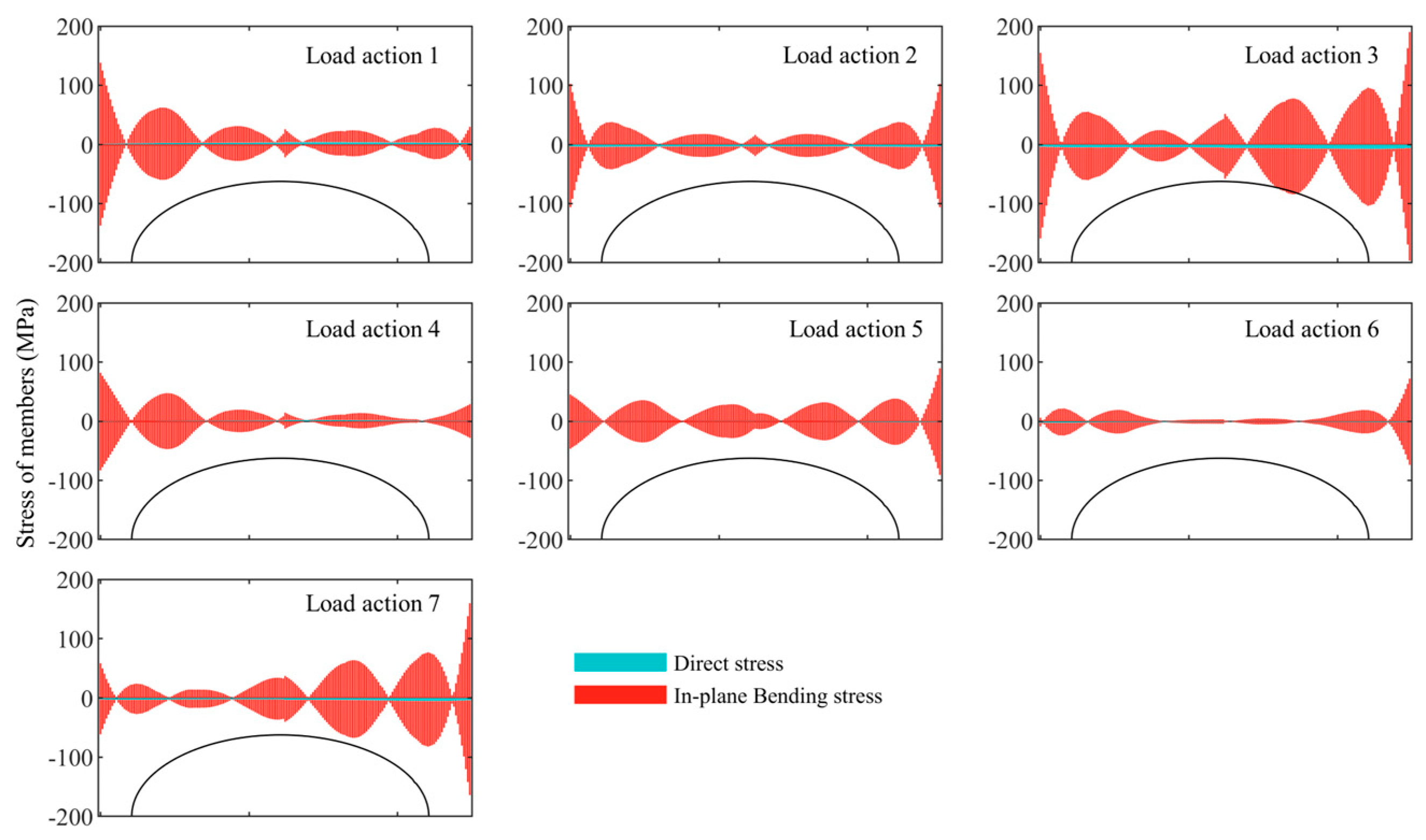
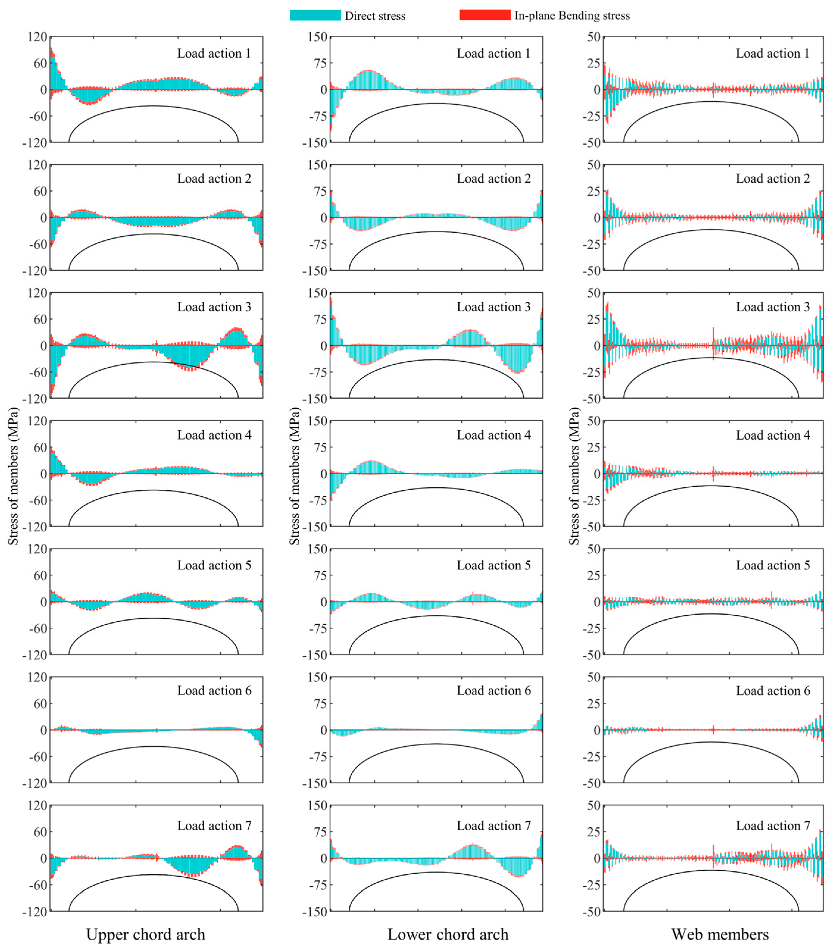
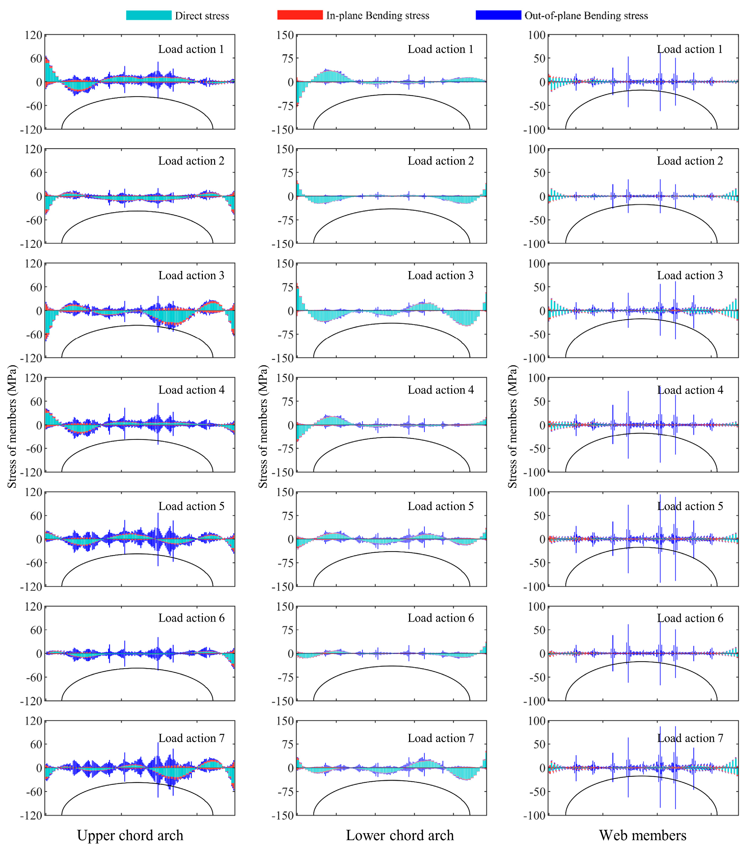
3.2.1. Stress of the Third Arch Frame
Figure 3,
Figure 4 and
Figure 5 show the stress distribution of the third arch frame under 7 load conditions for 3 structures. Similarly to the deformation analysis, when the wind load and snow load acted, respectively, the stress in the members showed the opposite trend. Therefore, when the two were combined, they would offset each other, and the stress of the member under the two variable load combinations was less than that under a single load. Therefore, under Load action 3, the member stresses were the largest, Load action 1 was the next, and when the wind load and snow load acted at the same time, the member stresses were relatively small.
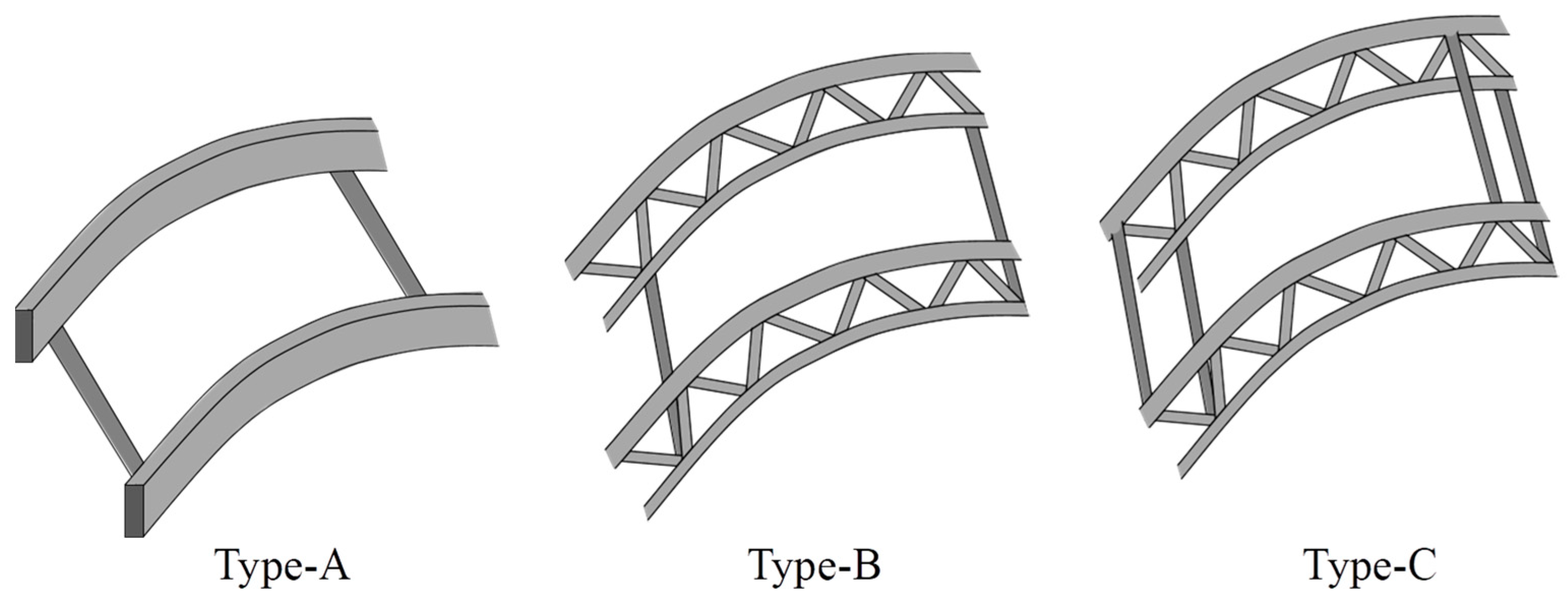
It can be observed that the Type-A structure mainly experienced in-plane bending stress, with a relatively small direct stress ranging from −7.9 to 4.0 MPa, while the out-of-plane bending stress was 0 MPa. The stress on the structural supports was the highest. For Type-B and Type-C structures, direct stress was mainly distributed on the components, with in-plane bending stress present but small, ranging from 0.7 to 25.6 MPa, while out-of-plane bending stress was 0 MPa. The stress at the lower chord support of the truss reached its maximum.
And the maximum combined stress of the Type-A structure was −196.6 MPa, with an average value of 45.9 MPa. For the Type-B structure, the maximum combined stress in the upper chord, lower chord, and web members was −113.1, 136.4, and 41.4 MPa, with corresponding average values of 22.3, 30.8, and 6.5 MPa. The maximum direct stress in members was 32.7 MPa, 110.9 MPa, and 33.9 MPa, with averages of 22.7 MPa, 31.6 MPa, and 5.4 MPa. For the Type-C structure, the maximum combined stress in the upper chord, lower chord, and web members was −91.5, 108.5, and 41.1 MPa, with average values of 17.4, 23.7, and 6.1 MPa. The maximum direct stress in members was 25.3, 87.4, and 35.5 MPa, with averages of 18.0, 24.3, and 5.2 MPa.
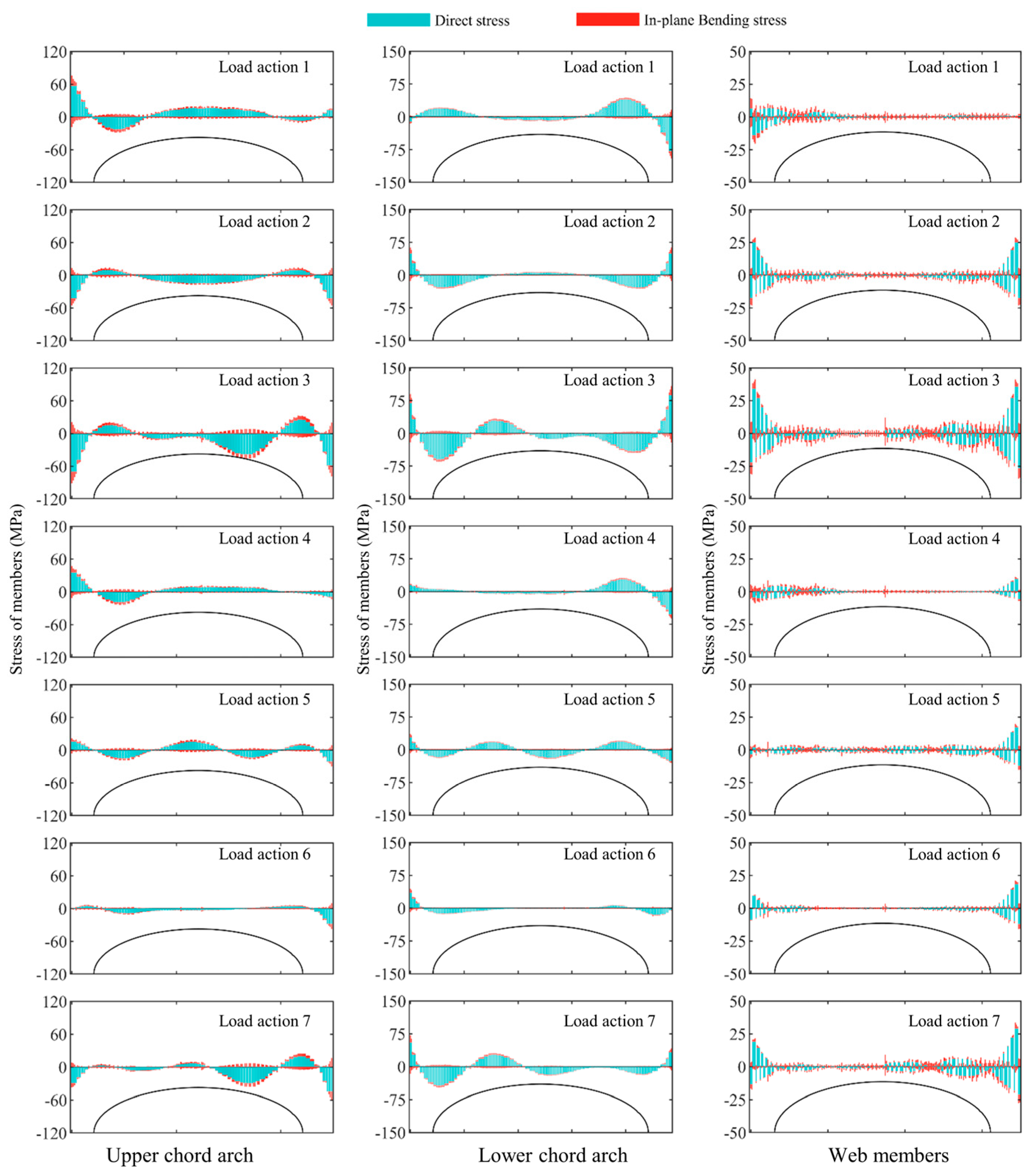
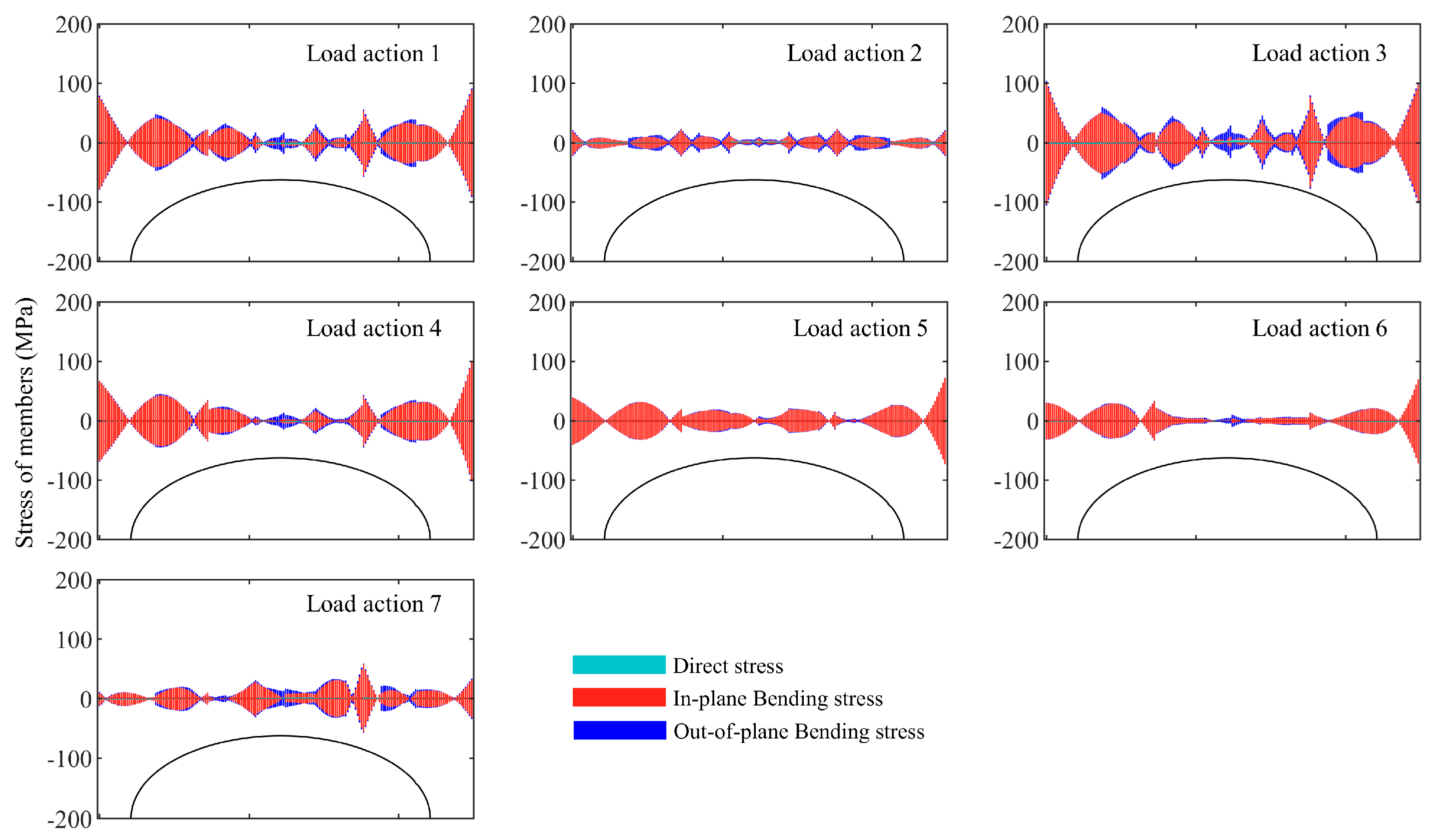
3.2.2. Stress of the Second Arch Frame
Figure 6,
Figure 7 and
Figure 8 show the stress distribution of the second arch under seven load conditions for three structures. It was observed that the stress distribution in the second arch of the three structures was similar to that of the third one, but all experienced out-of-plane bending stress. The stress in the second arch was less than that in the third arch. Under Load action 3, the maximum combined stress in the Type-A structure was −189.6 MPa, with an average value of 35.8 MPa. The maximum out-of-plane bending stress on the arch frame was 22.0 MPa, with an average value of 5.3 MPa.
In the Type-B structure, the maximum combined stress in the upper chord, lower chord, and web members was −94.8, 110.3, and 42.4 MPa, with average values of 20.1, 24.9, and 7.8 MPa. The maximum direct stress in the members was 19.0, 87.4, and 23.9 MPa, with average values of 16.9, 23.3, and 5.0 MPa. The maximum out-of-plane bending stress in the members was 22.4, 28.8, and 25.6 MPa, with average values of 3.6, 4.2, and 4.2 MPa. The out-of-plane bending stress mainly existed in the connection area of the tie rod, with 0 MPa near the support. Similarly, in the Type-C structure, the maximum combined stress in the upper chord, lower chord, and web members was −78.6, 87.2, and 61.5 MPa, with average values of 15.4, 20.2, and 5.8 MPa. The maximum direct stress for the members was 18.6, 69.6, and 23.3 MPa, with average values of 13.9, 19.2, and 3.6 MPa. The maximum out-of-plane bending stresses were 22.4, 28.8, and 25.6 MPa, with average values of 4.3, 1.8, and 3.1 MPa.
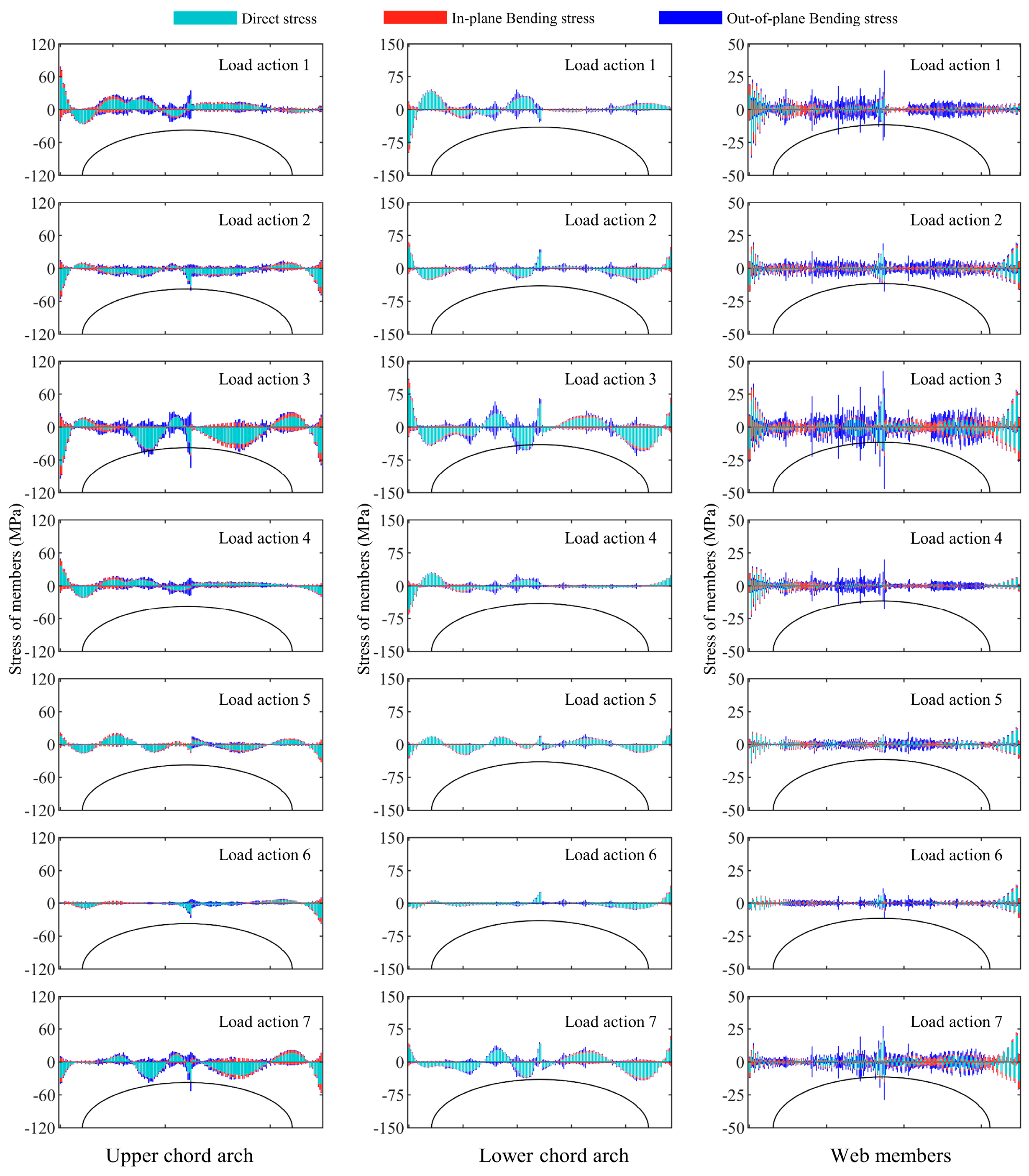
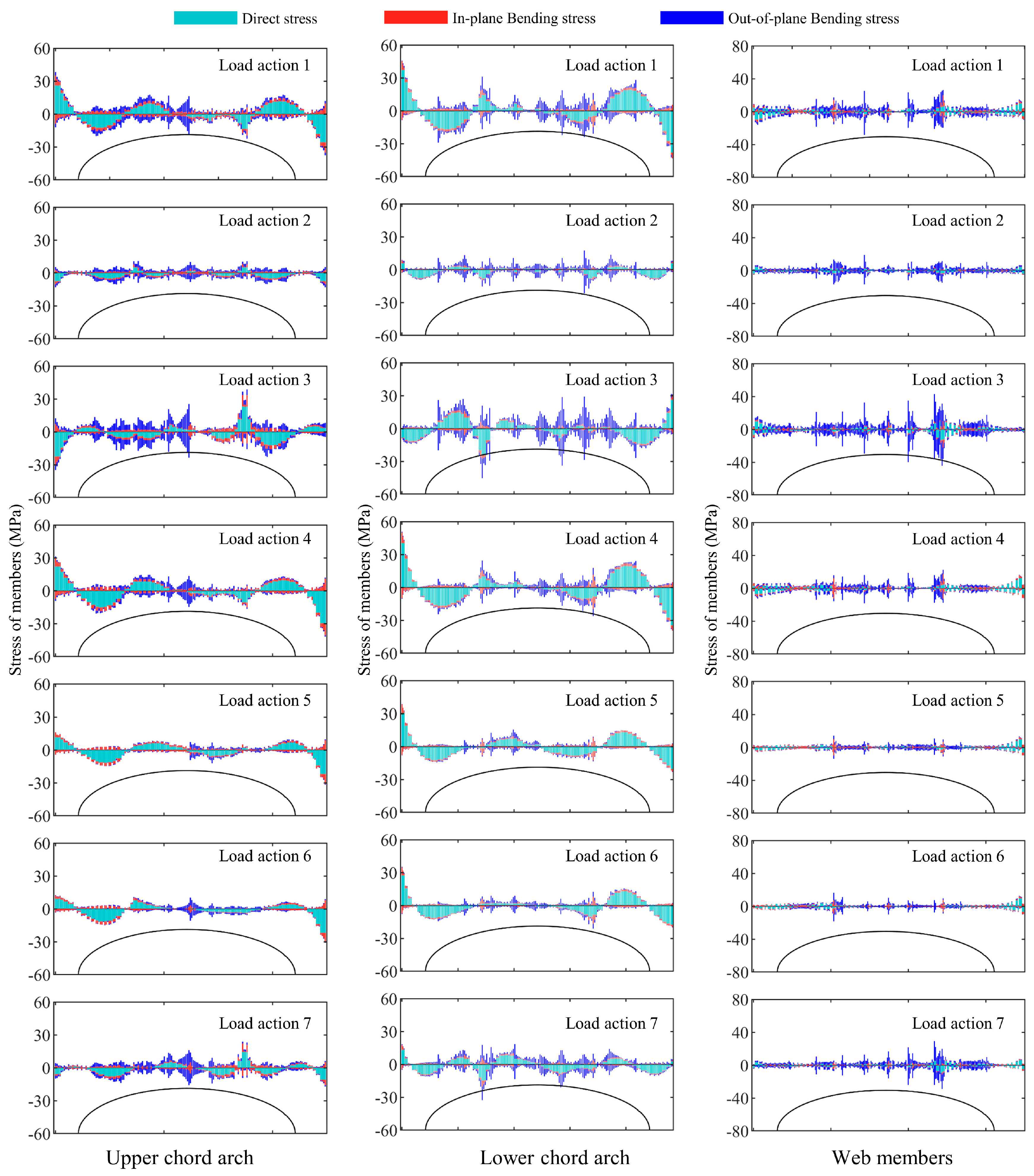
3.2.3. Stress of the First Arch Frame
Figure 9,
Figure 10 and
Figure 11 show the stress distribution of the first arch under seven load conditions for three structures. It was observed that the distribution of stress in the first arch was similar to that of the second one, but the stress values were much smaller than those of the second arch frame. Under Load action 3, the maximum combined stress in the arch frame of the Type-A structure was −105.5 MPa, and the average value was 27.5 MPa. In the Type-B structure, the maximum combined stress in the upper chord, lower chord, and web members was −38.7, −45.2, and 44.3 MPa, with average values of 7.7, 9.4, and 6.4 MPa. The maximum direct stress in the members was 23.2, 26.2, and 9.3 MPa, with average values of 5.3, 6.9, and 2.4 MPa. The maximum out-of-plane bending stress in the members was 20.0, 27.3, and 33.3 MPa, with average values of 3.4, 4.4, and 5.3 MPa. Similarly, in the Type-C structure, the maximum combined stress in the upper chord, lower chord, and web members was 36.9, 31.1, and 49.6 MPa, with average values of 7.9, 7.8, and 4.8 MPa. The maximum direct stress in the members was 27.2, 23.6, and 12.3 MPa, with average values of 5.6, 7.3, and 2.9 MPa. The maximum out-of-plane bending stresses were 21.5, 12.1, and 45.2 MPa, with average values of 4.8, 1.7, and 3.0 MPa.
Upon analyzing the three sets of data, the differences in stress distribution among the three arch frames were manifested as follows. The stress was greatest in the third arch frame and smallest in the first one. Under Load action 3, the Type-C structure showed a decrease in the average combined stress in the third arch by 22.1%, 22.9%, and 5.8% compared to the Type-B structure. Similarly, the average combined stress in the second arch decreased by 23.7%, 18.8%, and 24.8%, respectively. In the first arch, the upper chord experienced a slight increase of 1.6% in combined stress, while the stress of the lower chord and web decreased by 17.3% and 25.4%, respectively. Compared to the Type-B structure, the average direct stress in the third arch of the Type-C structure was lower by 20.6%, 23.1%, and 4.8%. The second arch showed an average reduction of 17.8%, 17.7%, and 29.5% in the direct stress of its three members. While the first arch’s upper chord experienced an average increase of 7.1%, 6.2%, and 18.2%. Regarding out-of-plane bending stress, the Type-C structure exhibited an average increase of 19.3% in the top chord of the second arch frame compared to the Type-B structure, while the bottom chord and web members decreased by 56.8% and 26.2%. In the first arch frame, the out-of-plane bending stress in the upper chord increased by an average of 30.0%, while the lower chord and web members decreased by 60.5% and 43.2%.
In summary, compared with the Type-B structure, the combined stress of most components in the Type-C structure was generally reduced, except for a slight increase in the upper chord of the first arch frame. The direct stress of the second and third arches significantly decreased, while the first arch increased. The out-of-plane bending stress of the upper chord slightly increased, but the stress values of the lower chord and web members decreased significantly.
3.3. Ultimate Bearing Capacity Analysis
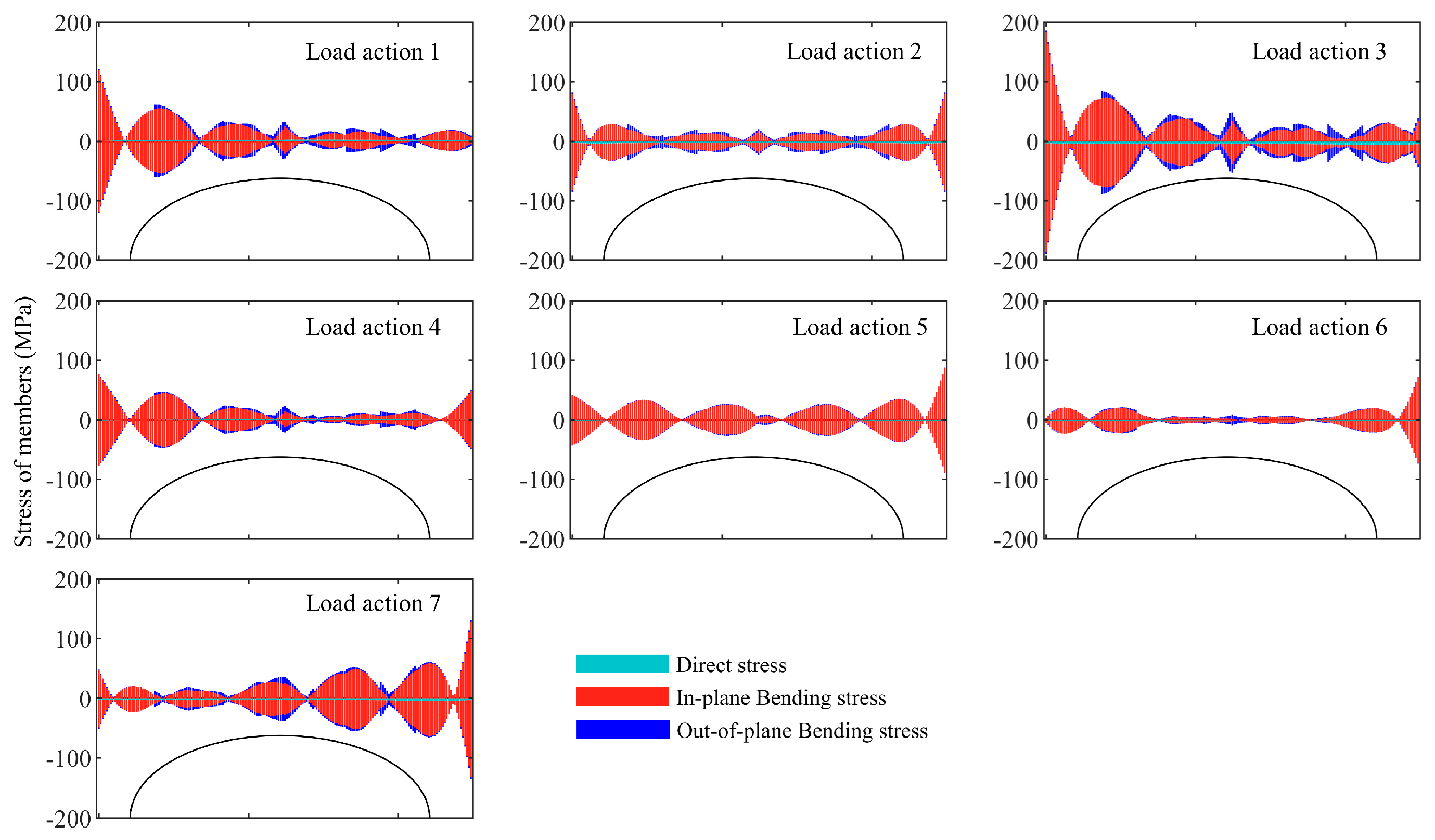
3.3.1. Load-Displacement and Load-Stress Relations of 3 Greenhouse Structures
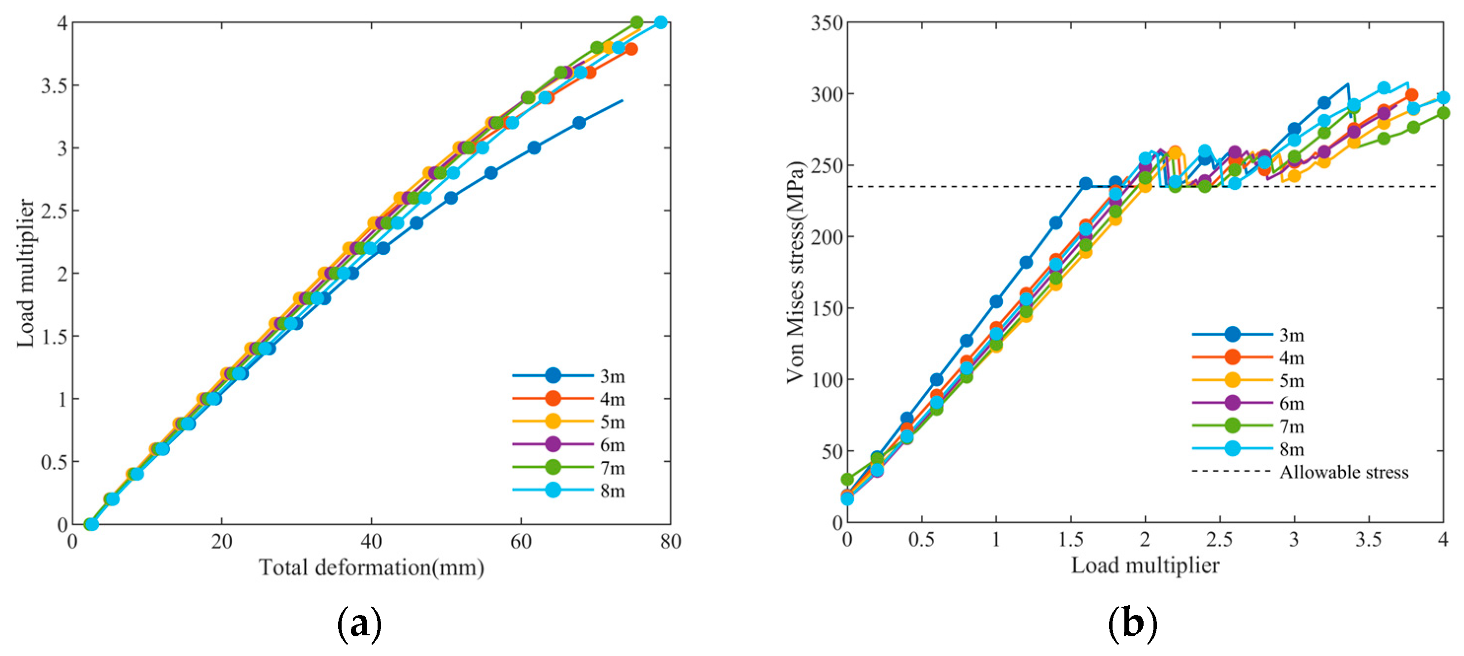
To obtain an accurate critical buckling load, a double nonlinear stability analysis was performed. The load-displacement and load-stress relationships throughout the process were tracked, as shown in
Figure 12. To more intuitively represent the ultimate load, the horizontal axis indicates the multiple of the initial load. It was observed that as the load increases, the stress of the three greenhouse structures before yielding were straight-line segments in equal proportion, indicating an elastic stress state. After yielding, the stress on the structures exhibited fluctuations but did not immediately fail, demonstrating a clear yielding phenomenon. After undergoing a relatively long plastic deformation process, the stress value on the structure gradually increased amid fluctuations until reaching its ultimate bearing capacity, indicating that the structure exhibited typical ductile failure. The Type-A structure was the first to yield, at a load equal to 1.0 times the initial load. When the load reached 1.82 times the initial load, the Type-B structure began to yield. Meanwhile, Type-C sustained a load at 1.86 times the initial capacity, indicating just a minor increase compared to Type-B. But it still exhibited a significant post-yielding increase. It could be concluded that Type-C has the highest ultimate bearing capacity, followed by Type-B, while Type-A has the lowest ultimate bearing capacity.
3.3.2. Failure Mechanisms of Three Structures
To thoroughly investigate the failure mechanisms of three structures,
Figure 13 illustrates the evolution of Von-Mises equivalent stress in the members of three structures at yielding and ultimate states. For the Type-A structure, the outer side of the arch at the support location first entered the yielding state. The Type-B structure yielded first at the arch support location, specifically on the inner side of the lower chord. In contrast, the Type-C structure first yielded at the tie rod where the second arch connects, while the remaining portion of the structure remained in an elastic state. As the load continues to increase until reaching the ultimate state, the Type-B structure exhibits yielding at multiple locations, including both end supports, the lower chord near the supports, and the middle section of the crossbeam. For the Type-C structure, yielding points primarily appeared on the tie rods and corresponding web members on the side where snow accumulates, while other positions of the arch remain in the elastic state.
In summary, the three greenhouse structures have experienced strength failure. The weaknesses of the Type-B structure and Type-A structure were mainly concentrated in the support area of the arch frame, while for the Type-C structure, its weak points were primarily manifested in the tie rods and the web members connected to them. Under the ultimate state, the stress at the arch frame supports in the Type-C structure remained within the elastic range, approaching the yield limit but without yielding. It can be inferred that the stiffness of the tie rods was enhanced by increasing the size of the upper tie rods, thereby altering the load-bearing mode of the structure and improving the overall load-bearing capacity.
3.4. Ultimate Bearing Capacity of Large-Span Insulated Plastic Greenhouses with Different Ridge Heights
Ridge height is a key design parameter for large-span insulated plastic greenhouses. Analyzing the impact of ridge height on its load-bearing capacity can provide theoretical guidance for the design of large-span insulated plastic greenhouses.
Figure 14 shows the load–displacement and load-stress relations of large-span insulated plastic greenhouses with different ridge heights. It can be observed from the figure that as the load increases, the deformation and stress curves of greenhouse structures with different ridge heights exhibit similar development trends. When the ridge height increased from 3 m to 8 m, the ultimate loads of the greenhouses were 1.58 times, 1.82 times, 1.98 times, 1.88 times, 1.9 times, and 1.84 times, respectively. Under the 1.98 times initial load (the ultimate load of the large-span insulated plastic greenhouse with a 5 m ridge height), the total deformations of these greenhouses were 37.1 mm, 33.5 mm, 33.3 mm, 34.2 mm, 34.8 mm, and 35.9 mm, respectively. It can be concluded that the ridge height has a significant impact on the ultimate load of the greenhouse structure. However, it was not the case that the greater the ridge height is, the stronger the ultimate bearing capacity of the greenhouse framework would be. The greenhouse structure with a ridge height of 5 m can bear the maximum load and exhibits minimal deformation.
4. Discussion
This study established 3D finite element models of three types of large-span insulated plastic greenhouses to analyze their deformation characteristics, stress distribution, and stability under seven load conditions. The ultimate bearing capacity of a large-span insulated plastic greenhouse with different ridge heights was mainly explored. The results showed that the double-layer tie rod and plane truss structure had the minimum deformation, the minimum stress, and the highest ultimate bearing capacity. The ridge height had a significant effect on the bearing capacity of the greenhouse structure. The research provided theoretical support for the configuration of structural components of a thermal insulation plastic greenhouse and offered a scientific basis for the optimal design of ridge height.
It was found that the most unfavorable load action for the structures was constant load and non-uniform snow load. Similar research conclusions have also been obtained in Ren et al. and Wang et al.’s research and structural analysis of solar greenhouse [
9,
21].
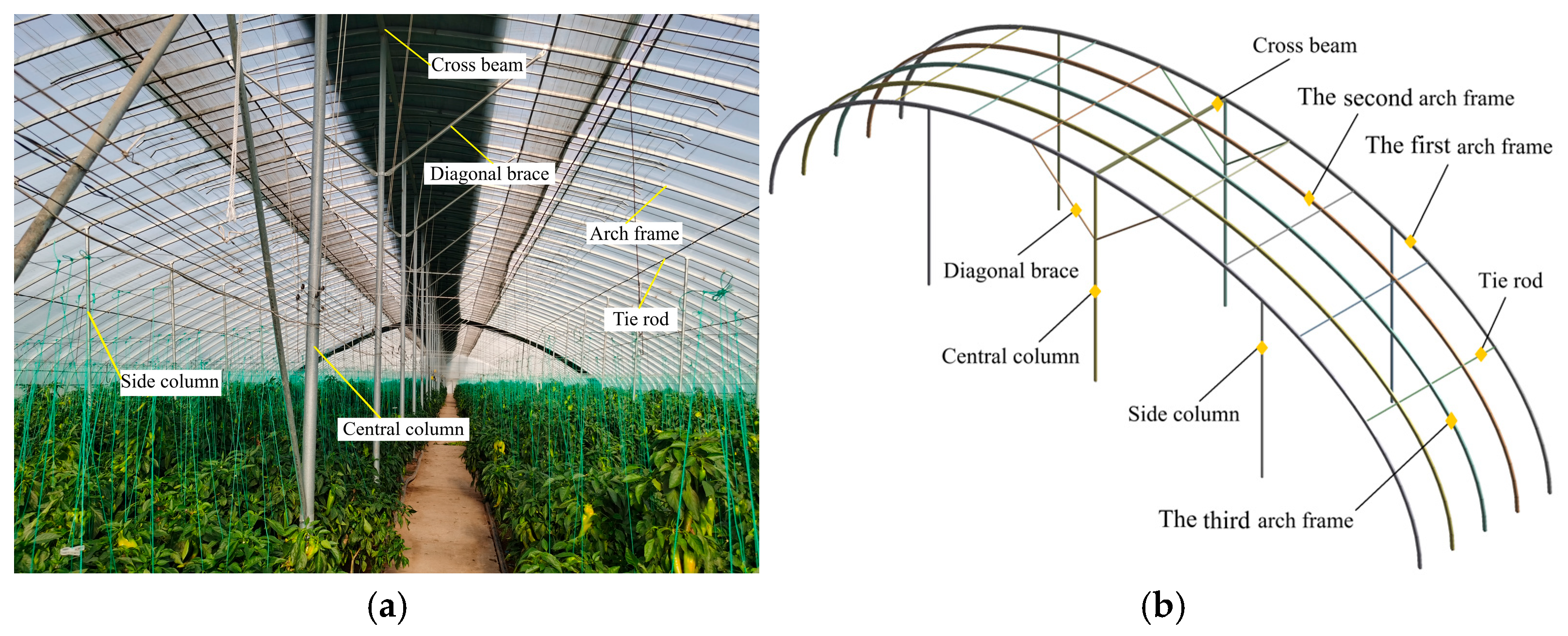
In a calculation unit, the load-bearing components of the large-span insulated plastic greenhouse include arch frame, tie rod, central column, side column, cross beam, and diagonal brace. The arch frame serves as the primary load-bearing component, while the main function of the tie rods is to connect five arch frames along their length. The first and fifth arch frames are equipped with central columns, side columns, and diagonal braces as vertical support components, exhibiting greater stiffness than the other arch frames and thus classified as main arch frames. In contrast, the second, third, and fourth arch frames are categorized as secondary arch frames. The structure exhibits symmetry. By analyzing the stress in the first, second, and third arch frames, the stress of the entire computational unit can be evaluated. This study found that although each arch frame bears the same external load, among the three structures, the first arch frame consistently showed the smallest stress, while the third arch frame exhibited the largest. For the Type-C structure, the combined stress was generally lower than that of the Type-B structure, except for a slight increase in the upper chord of the first arch frame. Notably, compared to the Type-B structure, the direct stress in the secondary arch frames (second and third arch frames) of the Type-C structure was significantly lower, while the direct stress in the first arch frame increased. This indicates a redistribution of stress in the Type-C structure following the installation of double-layer tie rods. It can be inferred that due to the lower stiffness of the tie rods in the Type-B structure, they cannot effectively transmit deformation and internal forces, resulting in relatively independent operation of each arch frame within the structural unit and a lower synergistic effect. In contrast, the Type-C structure enhanced the stiffness of horizontal members by increasing the number of tie rods and optimizing their layout. This allowed the load effects on the second and third arch frames to be more effectively transmitted to the main arch frames via the tie rods, enabling shared external load-bearing and reducing the overall stress levels and deformation of the greenhouse structure. Wang et al. [
10] examined the impact of tie rods on the stability of planar trusses within solar greenhouses and arrived at conclusions akin to those presented in this paper. However, they did not explore the effects of tie rods on stress redistribution between arches and out-of-plane bending stress.
Under the most unfavorable load combination, the Z direction displacement of the Type-C structure decreased by 1.3 mm compared to the Type-B structure, while the total displacement decreased by 5.1 mm. In the Type-C structure, the out-of-plane bending stress of the upper chord in the second arch frame increased by an average of 19.3%, while the lower chord and web members decreased by an average of 56.8% and 26.2%, respectively. In the first arch frame, the upper chord increased by an average of 30.0%, while the lower chord and web members decreased by an average of 60.5% and 43.2%. Although the out-of-plane bending stress of the upper chord increased, this stress in the lower chord and web members significantly decreased, leading to an overall reduction in out-of-plane stress across the entire arch frame. Under the most unfavorable load combination, the analysis of nonlinear instability mechanisms and ultimate bearing capacities for three structures revealed that the Type-C structure exhibits the highest ultimate bearing capacity. This suggests that the installation of double-layer tie rods in the Type-C structure enhanced horizontal stiffness and support, reducing displacement in the Z-axis direction, effectively mitigating the effect, decreasing out-of-plane bending stress, and ultimately improving the structure’s ultimate bearing capacity.
Ridge height is a key design parameter for large-span insulated plastic greenhouses. There have been many studies on the influence of greenhouse ridge height on lighting environment and ventilation rate [
22,
23,
24]. However, it is often treated as a fixed geometric parameter in most greenhouse structural studies when analyzing structural safety. Shi et al. [
25] discovered through full-scale model loading tests that ridge height had the greatest impact on the bearing capacity of truss-arch plastic greenhouse structures. This study found that the ridge height had a significant impact on the ultimate bearing capacity of large-span insulated plastic greenhouse structures. Moreover, the results showed that with the increase in ridge height, the ultimate bearing capacity of long-span insulated plastic greenhouse increased first and then decreased. When the ridge height was 5 m, the long-span insulated plastic greenhouse achieved a balance between stiffness and geometry, and its ultimate bearing capacity reached the maximum. Similarly, Hu et al. [
26] discovered that the ridge height influences the in-plane buckling and postbuckling behavior of parabolic arches significantly in their study on the in-plane nonlinear elastic stability of parabolic steel arches. When studying the in-plane nonlinear elastic stability of concrete-filled steel tube truss arch, Liu et al. [
27], Hu et al. [
28], and Guo et al. [
29] also found that the ridge height of arches has a significant influence on the stability capacity. The stability capacity reduces as the rise-to-span ratio declines. Our finding provides theoretical support for determining the ridge height of large-span insulated plastic greenhouses from a structural bearing capacity perspective.
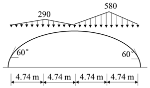
Based on GB/T 51183-2016 load code for agricultural greenhouse structures, the load return period of large-span insulated plastic greenhouse is relaxed to 20 years. The basic wind pressure and basic snow pressure were 410 and 290 N/m2, respectively, which were suitable for the climatic conditions in most areas of the Huang Huai River Basin. The arch structure employed the commonly used planar truss and rectangular tubes in greenhouses. The research conclusions apply to the design requirements of a large-span thermal insulation plastic greenhouse in this area. In the follow-up work, we will be committed to exploring the applicability of these conclusions in different climatic regions. Considering the climatic conditions of the construction site for large-span insulated plastic greenhouses, including strong winds and rainstorms, we will analyze their impact on the structural stability of the greenhouse and develop a more comprehensive and universally applicable design guideline.
This study focused on the mechanical properties of large-span insulated plastic greenhouses with various structures under permanent, wind, and snow loads. During the research process, crop loads were not considered, nor were the potential impacts of different greenhouse crops, thermal effects, or dynamic wind loads on the research outcomes discussed. Future research should build upon the current findings and further examine the influence of crop load on greenhouse structures.
This study primarily relies on numerical simulation research. Experimental verification faces significant technical difficulties. On the one hand, experimental verification requires the construction of full-scale specimens and relies on special facilities such as wind tunnels and loading systems, which are subject to equipment scale and test costs [
30,
31]. In engineering practice, scaled models are often used for approximate simulation. On the other hand, the actual engineering is a multi-directional coupling load, and the experimental loading system is difficult to achieve accurate reproduction, resulting in systematic deviation between the experimental data and the actual engineering response. Although numerical simulation has significant advantages in modeling complex boundary conditions such as material nonlinearity and contact friction, the establishment of a highly reliable calculation model still needs to be verified by a professional mechanical experiment platform. The construction of a three-level verification system, including numerical simulation, scale experiment, and full-scale monitoring, can improve the engineering applicability of the calculation model, which should be the subject of future research.


 ,
, 


