1. Introduction
Rice seedling pot throwing is an efficient rice planting technology that plays a significant role in rice production [
1]. However, existing rice seedling pot throwing machinery still faces issues such as floating of the pot seedlings after transplanting and low uprightness, which lead to prolonged seedling growth periods [
2,
3,
4]. Therefore, it is necessary to conduct research on the mechanism of the pot seedling throwing process. However, this process is complex, involving interactions between machinery, pot seedlings (pot soil, stems, and leaves), and paddy field soil. Moreover, due to the difficulty in observing and detecting the interaction mechanisms within the paddy field soil, there is a lack of relevant theoretical guidance for optimizing the working and structural parameters of rice seedling pot throwing machinery [
5]. Therefore, employing the DEM to construct a coupling model of the furrow opener–soil–pot seedling system and exploring the interactions between the furrow opener and soil, as well as between the soil and pot seedling, can lay a theoretical foundation for improving the uprightness of pot seedlings and optimizing the operational parameters of throwing machinery.
The coupled modeling of furrow opener–soil–pot seedling systems is based on paddy soil models, with the the DEM serving as the primary methodology for simulating the external dimensions and contact characteristics of research subjects [
6]. Using the draw plate method, in combination with soil simulation parameters of paddy fields calibrated by the collapse test, the operation process of the furrow opener can be analyzed and the optimization of the furrow opener parameters can be carried out [
7]. Puncture tests further calibrate bonding parameters of hole-tray seedling potting soil [
8,
9]. EDEM 2022.2 software can simplify the whole hole-pot seedling process into a model composed of potting soil and stalks, and the pot seedling–soil complex can be modeled and shear characterization studied [
10]. The discrete element coupling model can also effectively simulate the dynamic performance of mechanical operations [
11,
12,
13,
14,
15]. Researchers have conducted comprehensive investigations across diverse scenarios: Zhu et al. [
16] developed a machine–straw–soil coupling dynamics model to analyze rotary tillage processes; Lin Jianxin [
17] established a spade cultivator–multiphase medium interaction model based on soil and straw property measurements from rice stubble fields; Wan et al. [
18,
19] constructed a licorice-soil–oscillating harvester coupling model to study system behavior linked to licorice distribution and soil characteristics. These findings collectively demonstrate the feasibility of developing a potting–soil–opener coupled model using the DEM.
However, synthesizing the above studies, it was found that the current research on coupled machinery–soil–plant system modeling mostly focuses on harvesting and tillage directions, and the simulation research on the dynamic response of pot seedlings in the process of throwing planting is still lacking. To this end, this study analyzes the mechanics of the seedling falling process, obtains the factors affecting seedling uprightness, calibrates paddy soil and seedlings, establishes the furrow opener–soil–pot seedling coupling model, reveals the dynamic evolution of the soil backfilling law in the process of rice pot seedling throwing, and clarifies the influence of the working parameters of the seedling throwing device and the structural parameters of the furrow opener in the coupling system on the uprightness of the seedling. It thus provides a theoretical basis for improving the uprightness of pot seedlings. The accuracy of the model is further verified through the comparative analysis of the results of the throwing stand test and the simulated throwing test. This study is expected to provide a reference for improving the uprightness of pot seedlings and provide technical support for the design and parameter optimization of rice throwing equipment.
2. Materials and Methods
2.1. Rice Pot Seedling Mechanized Planting Upright Process
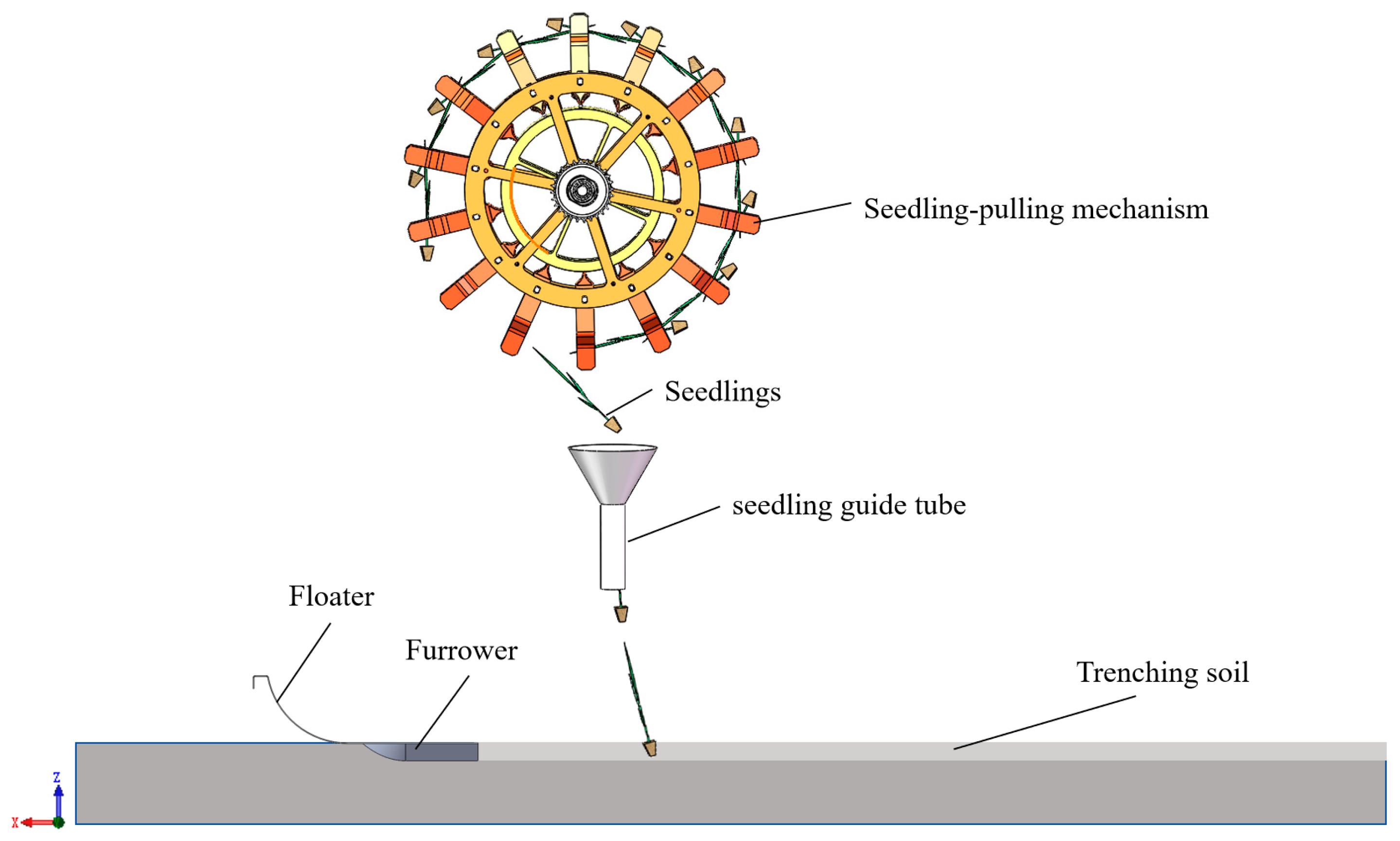
The rice pot seedling mechanical throwing system comprises a seedling extraction mechanism, furrow opener, rice pot seedlings, and paddy soil (
Figure 1), with its operational quality governed by extraction mechanism parameters, furrow opener–paddy soil interaction dynamics, and seedling intrinsic properties. The rice throwing process involves three sequential phases—seedling extraction, soil furrowing, and seedling embedment—where soil furrowing and seedling extraction operate synchronously. During the embedment phase, seedlings rapidly settle onto the furrow bed under the combined action of seedling guide tube initial velocity and gravitational acceleration, achieving seedling uprightness through paddy soil backflow effects. To address the limitations in visualizing the dynamics of the pot seedling after exiting the seedling transfer tube, a DEM-based coupled model was developed using collapse test calibration parameters, enabling mechanistic analysis of correlations among seedling-throwing device kinematics, soil rheological characteristics, and seedling uprightness metrics. These findings provide theoretical foundations for furrow opener structural optimization and operational parameter regulation in high-speed rice throwing systems.
2.2. Mechanical Characterization of Rice Potted Seedling Trenching and Establishment
In order to investigate the factors affecting the uprightness of rice potted seedling planting, the process of rice potted seedling planting uprightness was analyzed. Center-of-mass dynamics were used to analyze the evolution of forces and velocities in the air and soil entry phases of the rice potted seedling after exiting the seedling transport cylinder, which can provide theoretical support for subsequent experiments [
20].
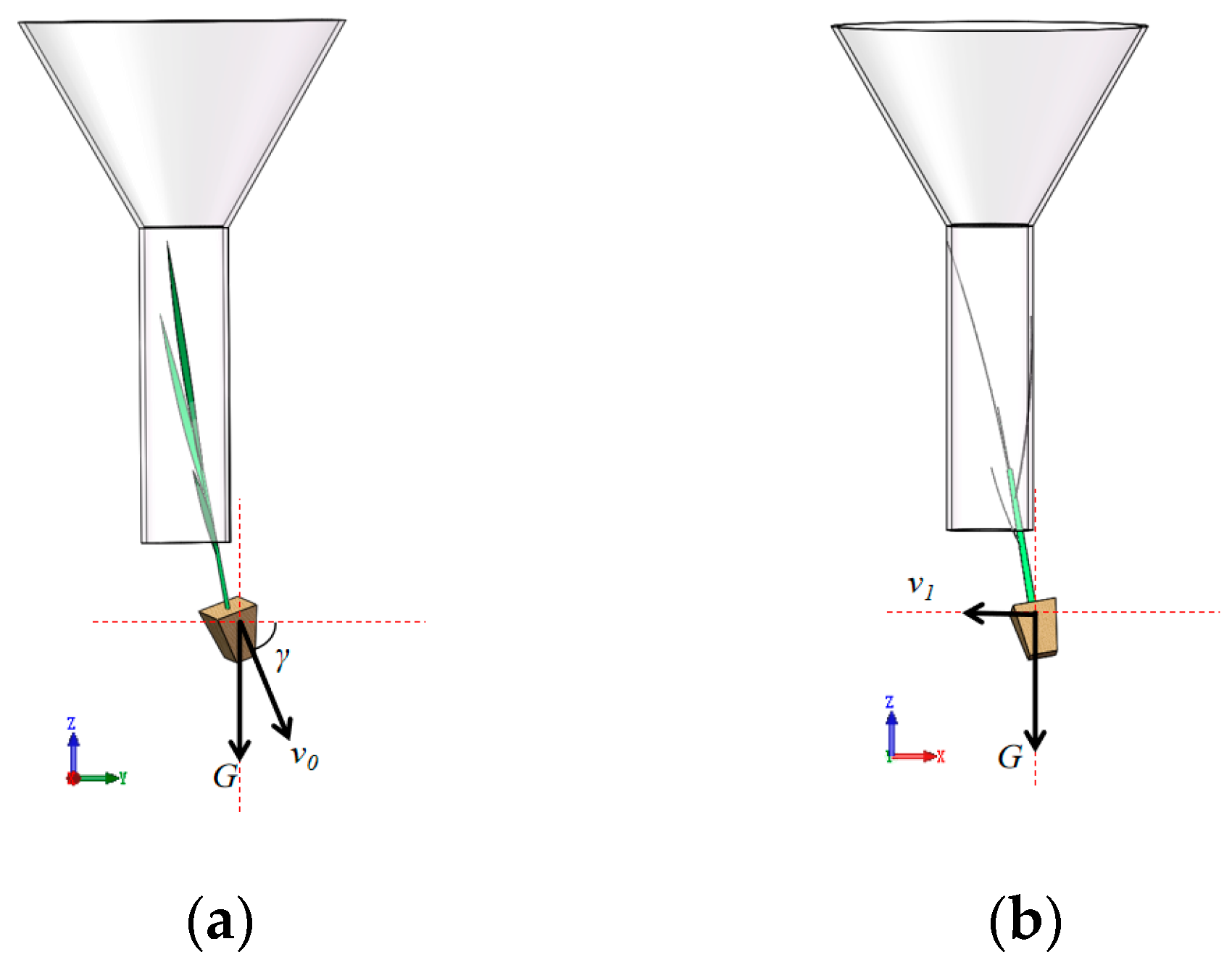
2.2.1. Rice Pot Seedlings Aerial Down Stage
During the airborne descent phase of rice pot seedlings (neglecting air resistance), the seedlings are subjected solely to gravitational force
G (with gravitational acceleration
g). Their kinematic behavior is characterized by a velocity component in the YOZ plane, with speed
v0 and angle
γ, and forward velocity
v1 in the XOZ plane, as illustrated in
Figure 2.
The velocity of the pot seedling before it falls into the soil and the value of the displacement deviation on the
Y-axis can be given by Equations (1) and (2):
where
v2Y is the speed of the pot seedling in the Y-axis, m/s;
v2z is the speed in the
Z-axis, m/s;
v2 is the falling speed before falling into the soil, m/s;
t is the falling time in the air after coming out of the seedling guide tube, s;
Lh is the distance from the bottom of the seedling guide tube to the surface of the mud, m;
g is the acceleration of gravity, m/s
2; and Δ
L is the displacement deviation value of the pot seedling in the
Y-axis, m.
Combined with the high-speed photographic observation test of the attitude of the seedling throwing movement in the previous period, the instantaneous speed of the seedling in the plane of YOZ from the seedling transmission cylinder v0 is in the range of 1.84–2.40 m/s; the forward speed of v1 in the plane of XOZ is in the range of 0.80–1.20 m/s, and the angle of the initial speed v0 with the Y-axis γ is in the range of 75.34–84.42°. And combined with the previous research and the design requirements of the machine, it can be seen that the distance Lh between the mouth of the rice transfer cylinder and the mud surface of the rice planting machine is 280 mm, and the value of v2 is in the range of 2.72–3.51 m/s.
2.2.2. Rice Pot Seedling In-Soil Stage
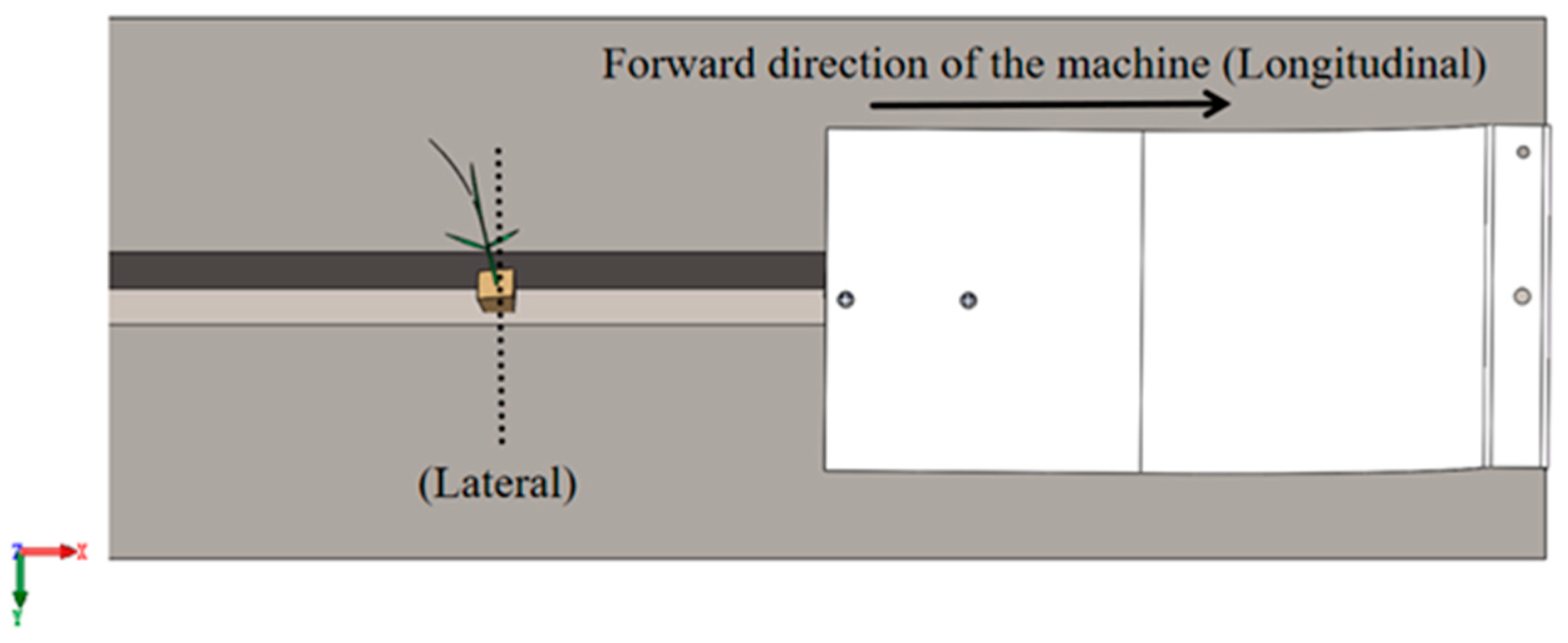
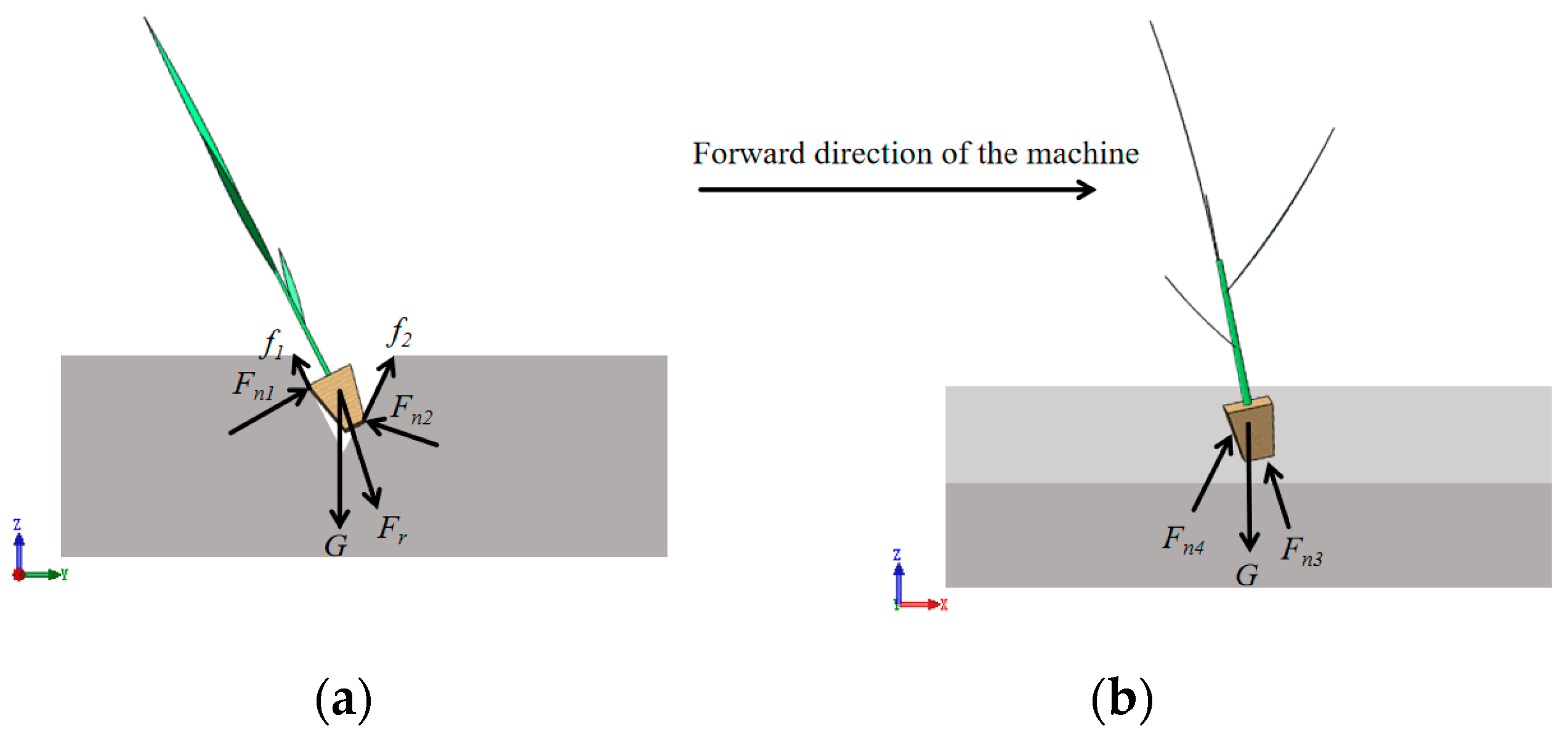
When the rice seedling falls into the trench, its top view is shown in
Figure 3. The paddy soil slows down the rice seedling’s movement in the forward speed direction (longitudinal) due to soil backfilling, and it will be squeezed by the soil to slow down the rice seedling’s movement in the forward speed transversal direction (transversal), as shown in
Figure 4.
Establishment of force equations for pot seedlings in the soil (3):
where
MZ is the total torque of the pot seedling, N·m;
G is the gravity force of the pot seedling, N;
m is the mass of the pot seedling, g;
Fr is the centrifugal force, N;
Fn is the normal force, N;
fn is the friction force, N;
lG is the force arm of gravity, m;
lFr is the force arm of the centrifugal force, m;
lFn is the force arm of the normal force, m;
lfn is the force arm of the friction force, m; and
r is the radius of centrifugal force, m.
Mechanical analysis showed that the rice seedling was synergistically regulated by transverse and longitudinal mechanics during soil entry. In the YOZ plane, squeezing forces Fn1 and Fn2 collectively suppressed transverse tilting through clamping effects. Simultaneously, in the XOZ plane, supporting forces Fn3 and Fn4, enhanced by paddy soil backflow, significantly reduced the total torque MZ. This torque reduction (MZ→0) directly contributed to longitudinal stabilization. Under multi-force coupling, soil forces exhibited a negative correlation with seedling uprightness, and parametric influences on seedling uprightness could be analyzed through anisotropic force quantification.
2.3. Rice Potting-Soil-Furrow Opener Coupling Model
2.3.1. Modeling Approach
- (1)
Soil tank modeling: Based on the pre-test data, the paddy soil that is favorable for pot seedlings erection was selected, and its paddy soil environment was the soil without bright water just after plowing, and its parameters such as water content, density and particle size distribution were determined. Based on the particle size distribution, the radius of the filled soil particles was 1 mm. According to the gradient of soil water content, the soil trench was divided into the surface layer (0–20 mm) and the deep layer (20–60 mm). Meanwhile, in order to avoid the interference of the side wall and cover the range of trenching, the size of the simulated soil trench was set to be 1000 mm (length) × 300 mm (width) × 60 mm (depth).
- (2)
Rice pot seedling modeling: Pot seedlings were selected at the period of three leaves and one heart, and their geometrical forms were determined through dimensional measurements and three-dimensional modeling, and the spatial coordinates of the filled particles were generated in the EDEM software.
- (3)
Trenching model simplification: The trench furrow opener and the floating plate were simulated according to homogeneous leveling, and their 3D models were assembled and converted to STL format and imported into EDEM software.
- (4)
Multi-step coupled modeling: The key to establishing a coupling model of furrow opener–soil–pot seedling systems using the discrete element method is to integrate multiple models constructed step by step, as shown in
Figure 5. Step 1: generation of soil trench particles—successively set the particle factory at the heights of 40 mm and 60 mm to generate the bottom and surface soil particles, and save the initial state file as “zero time” after the completion of the generation. Step 2: setting up the motion of trenching—position the model of the furrow opener to the front of the soil trench, and assign the translation speed. Step 3: pot seedling falling simulation, trenching within the soil trench, and translation speed assignment—when trenching to the middle of the soil trench, set the particle factory 5 mm above the end of the trench, and define the falling time, speed, and angle based on the soil backfilling characteristics and pot seedlings mechanical analysis. Step 4: simulation parameter setting—set the Rayleigh time step size of 20%, the data storage frequency of 0.01 s, and the total simulation length to 0.5 s after contact parameter calibration.
2.3.2. Calibration and Validation of Model Parameters
Accurate model parameters can precisely simulate the mechanical and behavioral characteristics of the furrow opener–soil–pot seedling system [
21]. In the coupled model, the driving parameters of the furrow opener model are consistent with the forward speed of the planting mechanism. The model parameters to be determined are the intrinsic parameters of the soil, pot seedling, and furrow opener; and the model parameters of soil particle–soil particle, soil particle–pot seedling particle, soil particle–furrow opener, and soil particle–floating plate interactions [
15,
22,
23].
- (1)
Calibration and validation of soil model parameters
In this study, the densities of soil at different depths were 1537.37 kg/m
3 and 1557.87 kg/m
3, respectively, using direct measurements, and the ranges of soil–soil and furrow opener–soil contact parameters were determined according to the relevant literature on paddy field soils [
24] and the GEMM database, where the furrow opener material was ABS. The “Hertz-Mindlin with JKR” contact model was used to simulate the viscosity of soil particles in paddy fields [
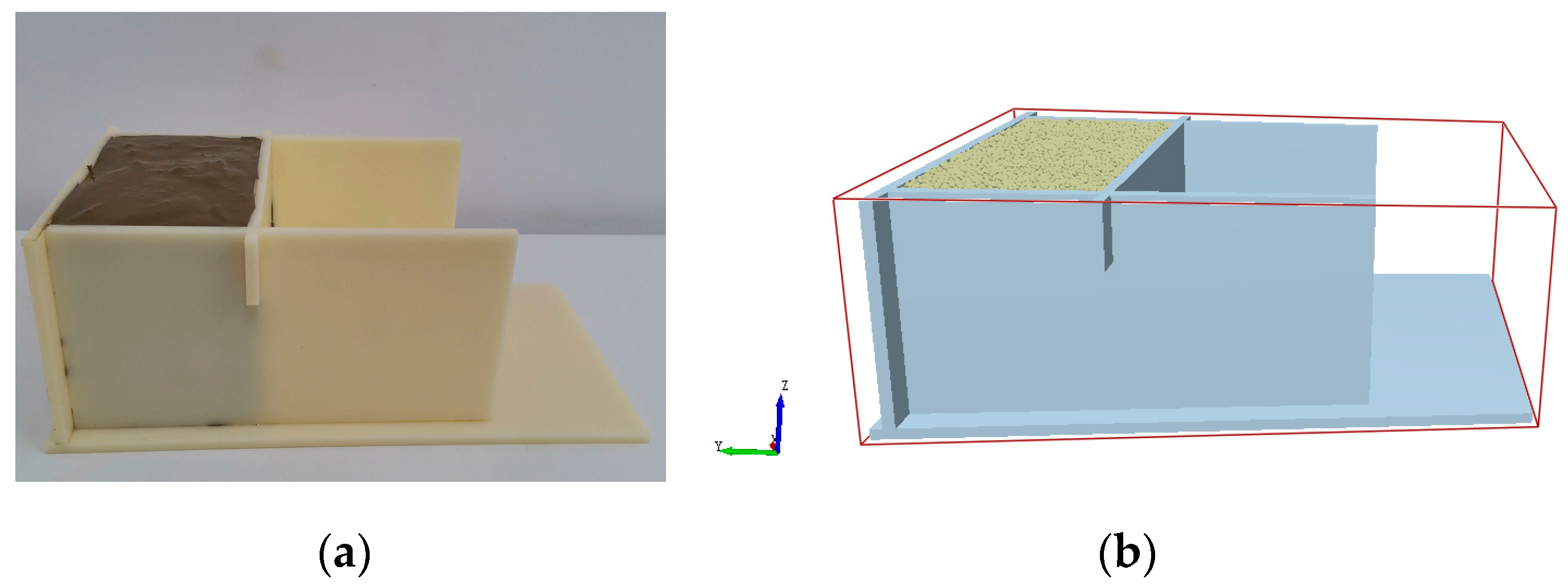
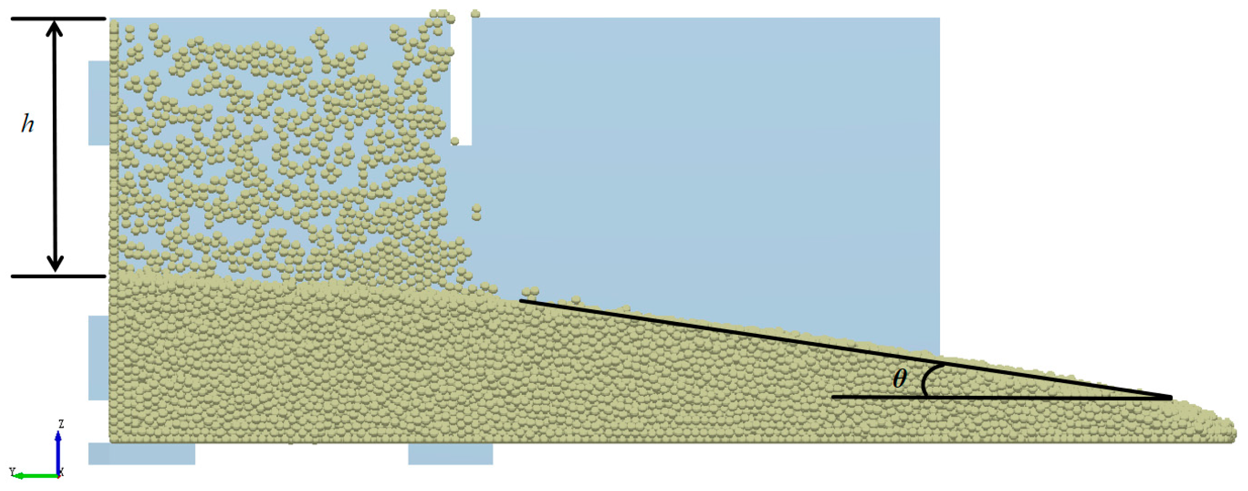
25]. The optimal parameter solutions of the soil–furrow opener model were determined by using the pumping plate method as shown in
Figure 6, calibrating the soil at different depths, and taking the soil accumulation angle
θ and the degree of collapse
h as the target values as shown in
Figure 7, as shown in
Table 1, where the contact parameters between the surface and deeper soils are the same as those between the deeper soils.
To further verify the accuracy of the two-layer soil model, the two-layer soil was mixed and compared with the actual collapse test through simulation [
26,
27], and the process is shown in
Figure 8. The calibrated parameters were imported into EDEM software, and the relative errors of the simulated and actual test double-layer soil model collapse degree were obtained at 0.85%, and the relative error of the expansion degree was 5.93%. The results of parameter validation show that the model parameters are accurate and can effectively simulate soil rheology.
- (2)
Calibration and validation of soil–pot seedling model parameters
In order to calibrate the soil–potting soil contact parameters, the stem and leaf were simplified into an equivalent mass rigid body model (a stem and leaf mass of 4.62 g and potting soil mass of 0.34 g), and the pot seedling drop test was carried out based on the range of soil–soil contact parameters (
Figure 9). By setting the drop height to 300 mm, the average depths of pot seedlings in the surface layer (0–20 mm) and the deep layer (20–60 mm) were measured to be 16.10 mm and 14.80 mm, respectively, and the optimal contact parameters were determined by combining data from the literature [
28], as shown in
Table 2. The test was conducted in two layers of soil, and the test showed that the relative error of the potting depth in the simulated two-layer soil model was 1.38% compared to the actual test.
2.4. Simulation and Bench Test of Trenching and Upright Planting of Rice Pot Seedlings
2.4.1. Experimentation with Different Out-of-Tube Postures of Pot Seedlings
The detachment attitude of the pot seedling out of the seedling guide tube was selected as the main test factor, and the test factors and levels were determined with the results of high-speed photographic observation of the pot seedling’s throwing motion attitude in the previous period and the results of the mechanical analysis of the pot seedling in the process of opening the furrow and standing up the seedling, as shown in
Table 3. When conducting a single-factor test for one factor, the other two factors were maintained at their intermediate levels, and the test was repeated three times. The data selected were the mean values of these repetitions.
Based on the analysis of pot seedling uprightness and mechanical response, the mechanism of detachment attitude on the effect of seedling standing was systematically investigated. The experimental indexes included the following:
- (1)
Soil kinematic velocities: real-time extraction of velocity field distributions using the EDEM particle vector mode;
- (2)
Lateral uprightness: angle between the furrow opener forward transverse plane, potting center axis, and horizontal plane (
Figure 10a);
- (3)
Longitudinal uprightness: angle between the center axis of the pot seedling and the horizontal plane in the plane of the forward direction of the furrow opener (
Figure 10b).
2.4.2. Testing of Different Furrow Opener Structural Parameters
The structural parameters of the opener were selected as the main test factors to analyze the uprightness of the pot seedling, in which the selection of the width, depth, and body length structural parameters of the opener was based on the width of the tube opening of the seedling guide tube, the required planting depth of the pot seedling, and the installation position of the opener, respectively. Experimental factors and levels are shown in
Table 4. Similarly, the effect of the structural parameters of the trenching opener on the effect of pot seedling uprightness was explored with an analysis of potting uprightness and stress, using a one-factor test and orthogonal test, with the same test indexes as above.
2.4.3. Simulation Verification Bench Test
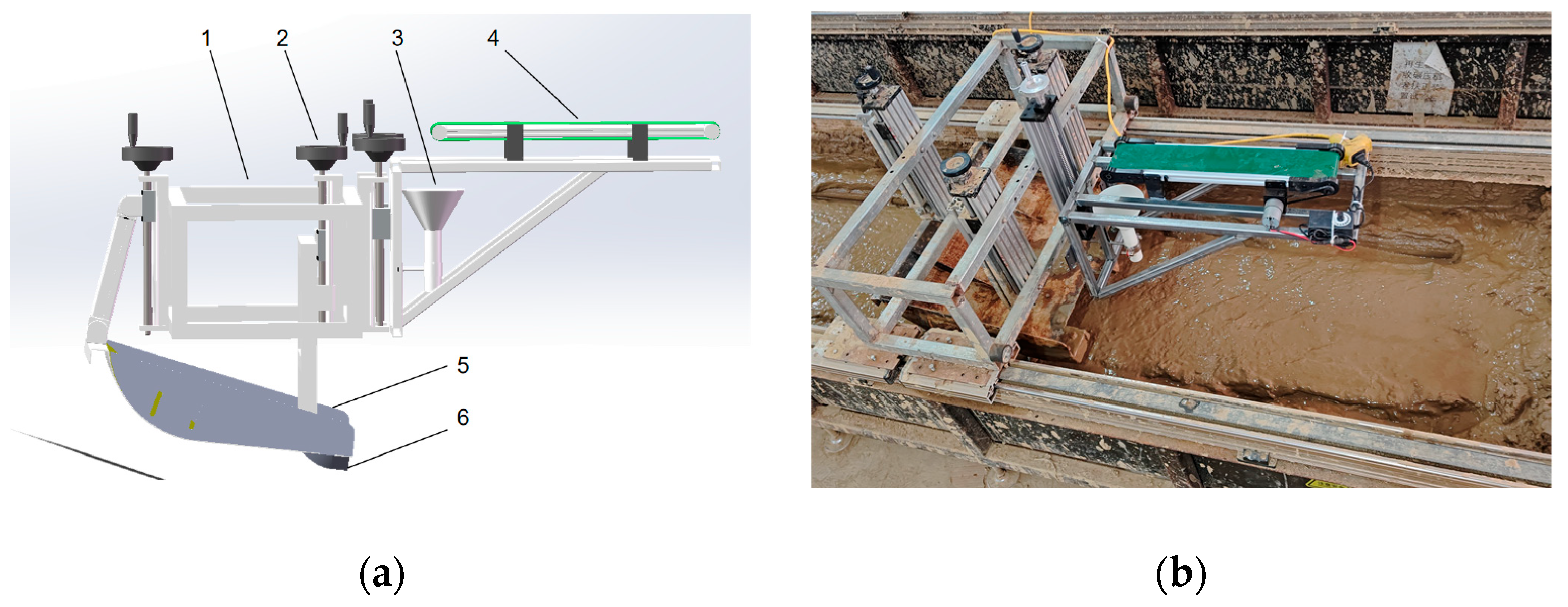
Verification of the optimal parameters of the simulation was carried out through bench tests on a test soil tank, and the three-dimensional modeling of the rice pot seedling uprightness test device was first carried out using SolidWorks 2019 three-dimensional drawing software, as shown in
Figure 11a. The test device, shown in
Figure 11b, consists of a frame, screw, conveyor belt, seedling delivery cylinder, floating plate, and furrow opener. When working, the test stand moves forward under the drive of the motor of the soil trough, and the furrow opener at the lower end of the stand carries out the furrowing operation; at the same time, the conveyor belt at the upper end conveys the pot seedling to the specified position and then falls into the furrowed soil after it is righted by the seedling delivery cylinder. In order to meet the initial conditions for inserting pot seedlings into the soil, the conveyor belt is set at a distance of 400 mm from the bottom of the seedling tube, with the bottom of the seedling tube at a distance of 280 mm from the mud surface; the distance between the seedling tube and the furrow opener is kept within 120 mm, and the forward speed of the platform is set to 0.8 m/s. The other main tools required for the test are a DH-190 automatic moisture meter, high-precision digital display angle tape, a ruler, a JJ1000 electronic balance, and so on.
3. Results
3.1. Rice Pot Seedling Furrowing Process into the Soil
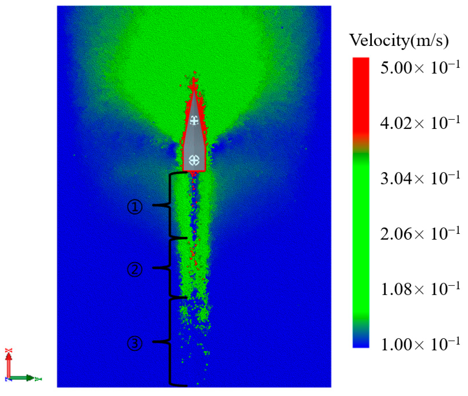
The simulation results show that soil disturbance during the operation of trenching is mainly concentrated in the edge curve area, which confirms that it is the core action site. The soil backfilling process presents three stages with dynamic characteristics (
Figure 12): ① Sidewall backfilling stage (0–0.15 s)—when the trenchers have just passed, the soil particles squeezed inside the trench can be released, migrating to the center of the trenching movement; the closer the particles are squeezed against the mud surface, the faster the soil backfilling occurs. ② Covering deposition stage (0.15–0.30 s)—as soil particles flow back, they slowly cover the bottom of the trench. ③ Stabilized formation stage (>0.30 s)—soil particle speed decreases to the point that they no longer move, and the trench type is fixed. The evolution law provides a theoretical basis for the optimal design of the trenching edge.
3.2. Factors Affecting Rice Potting Uprightness
3.2.1. Effect of Pot Seedling Disengagement Posture on Pot Seedling Uprightness
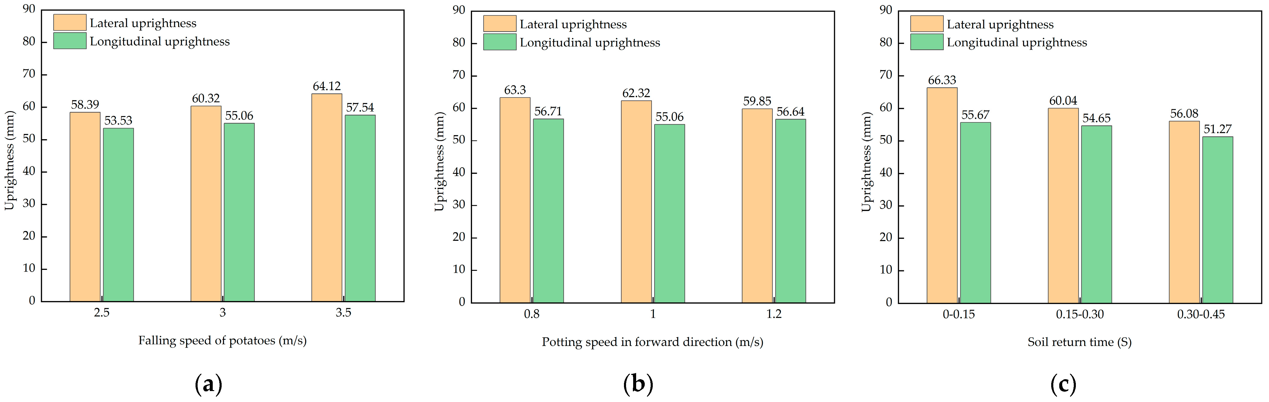
Impact of falling speed: As shown in
Figure 13a, the uprightness of pot seedlings is positively correlated with falling speed (2.5–3.5 m/s), reaching maximum values for both lateral and longitudinal uprightness (73.12°, 67.54°) at 3.5 m/s. The falling speed primarily affects the lateral uprightness of the pot seedlings. An analysis based on Formula (3) reveals that the greater the speed, the deeper the pot seedlings descend, increasing soil resistance against the seedlings and reducing the torque on the seedlings after they enter the soil, which impedes the tilting movement of the seedlings and enhances their uprightness.
Impact of forward speed: As shown in
Figure 13b, the uprightness of pot seedlings is negatively correlated with the forward speed (0.8–1.2 m/s), with the lateral and longitudinal uprightness being optimal at 0.8 m/s (73.30°, 66.71°). The forward speed primarily affects the longitudinal uprightness of pot seedlings. In the direction of forward speed, due to the trenching process pushing soil particles forward, the number of particles supporting the pot soil at the same height in this direction is significantly lower than on both sides of the trench. Therefore, under low-speed conditions, the rotational movement of pot seedlings is smaller, the deviation is less, and the uprightness of the pot seedlings is higher.
Impact of soil backfilling time: As shown in
Figure 13c, the uprightness of pot seedlings was negatively correlated with soil backfilling time (0–0.30 s), and pot seedlings had the highest degree of uprightness (72.33°, 67.67°) when they fell in the “sidewall backfilling stage” (0–0.15 s). At this stage, the soil particles were not completely backfilling to the bottom of the trench, and the force released from the soil particles extruded by the openers increased the force on the pot seedlings, which further reduced the rotation of the pot seedlings; then (>0.15 s), the backfilling was weakened, and the resistance was reduced, resulting in an increase in the amount of deflection and a decrease in uprightness.
As can be seen from the analysis of orthogonal tests carried out in
Table 5, R
VQ > R
T > R
VX; that is, the degree of influence of test factors on the measure of pot seedling uprightness is in the order of V
Q (forward speed) > T (reflux time period) > V
X (drop speed). Moreover, when the falling speed is 3.5 m/s, the soil reflux period is 0–0.15 s. When the pot seedlings fall into the trench, and the forward speed is 0.8 m/s, the pot seedlings fall into the trench with the best uprightness, and the effect of seedling erection is good.
3.2.2. Influence of Furrow Opener Structural Parameters on Pot Seedling Uprightness
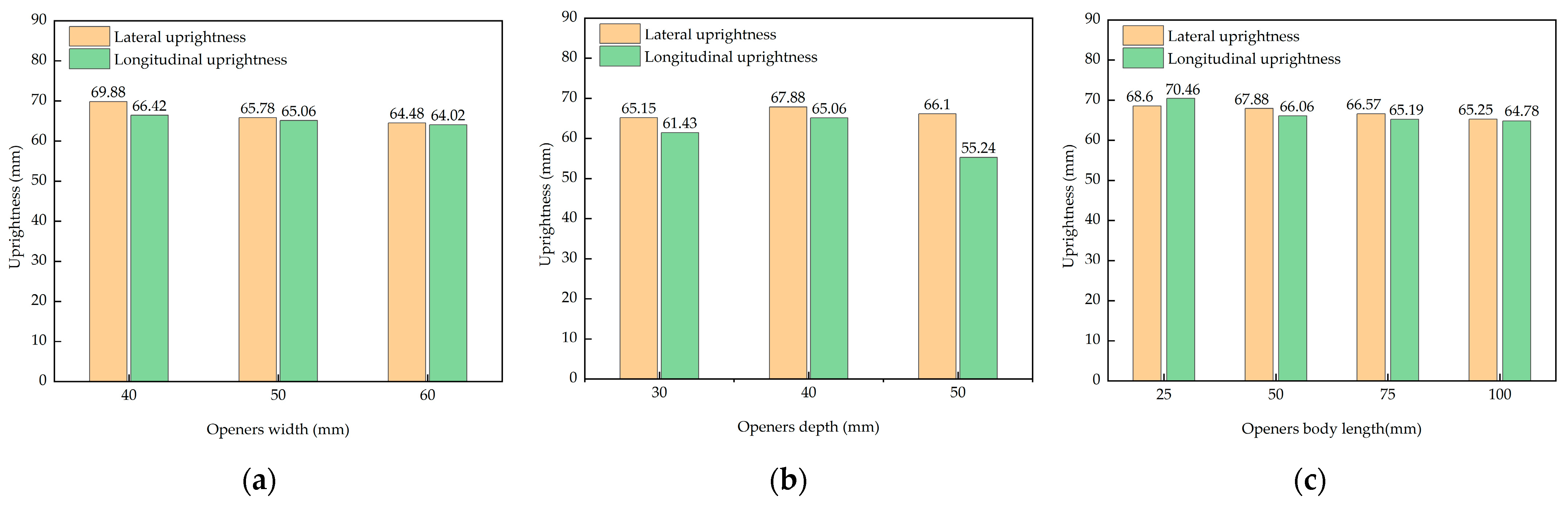
Impact of width: As shown in
Figure 14a, there was a significant negative correlation between the width of openers and the uprightness of pot seedlings. At a width of 40 mm, the horizontal and vertical uprightness reached maximum values (69.88°, 66.42°). The smaller the width of the openers, the narrower the trench opened, resulting in a greater clamping effect of soil particles on the potting soil in all directions, which impedes the tilting movement of the pot seedlings and increases the uprightness of the pot seedlings.
Impact of depth: As shown in
Figure 14b, uprightness showed a nonlinear response with increasing depth, and the lateral and vertical uprightness values were optimal at 40 mm (67.88°, 64.06°). At the same width, the deeper the trench, the steeper the trench slope, which in turn leads to inconsistent backfilling. This can be seen in the trenching depth of 40 mm, where the trench is the shallowest and the backfilling effect is the most significant, resulting in the largest soil particle entrapment in the potting soil.
Impact of main body length: As shown in
Figure 14c, the main body length was negatively correlated with uprightness, which was the greatest at 25 mm (68.60° in the lateral direction and 70.46° in the longitudinal direction). The shorter the length of the openers, the shorter the soil particle backfilling time and, at the same time, the more soil particles are backfilled, increasing the effect of potting soil clamping.
To further characterize the effect of the structural parameters of the openers on the uprightness of the pot seedlings, a Box–Behnken test was conducted to investigate the most favorable opener parameters for pot seedling uprightness. The results are shown in
Table 6 below.
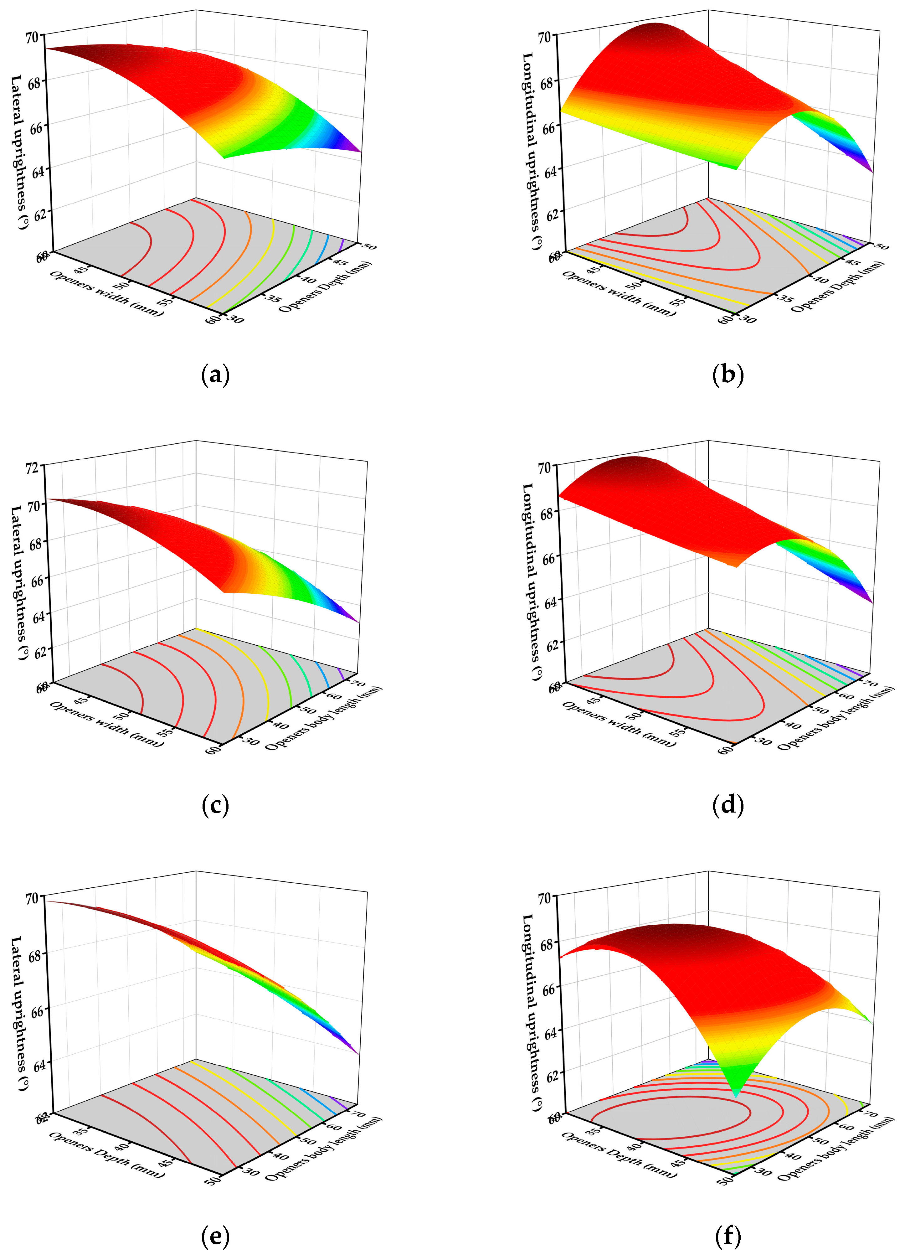
Response surface analysis based on Design-Expert 12 showed that the interaction of the structural parameters of the furrow opener significantly (p < 0.05) affected pot seedling uprightness:
Width–depth interaction (
Figure 15a,b): lateral uprightness decreases with increasing width or depth, reaching a maximum at 40 mm (width) × 30 mm (depth); longitudinal uprightness is optimal at 40 mm (width) × 40 mm (depth), with increasing depth triggering nonlinear decay.
Width–body length interaction (
Figure 15c,d): lateral uprightness is highest at 40 mm (width) × 25 mm (length), with both increasing width and length weakening the entrapment effect; longitudinal uprightness peaks at 40 mm (width) × 55 mm (length), with too long a length leading to delayed particle coverage.
Depth–body length interaction (
Figure 15e,f): the maximum value of lateral uprightness was located at 40 mm (depth) × 25 mm (length), with increasing depth or length exacerbating soil support dispersion; longitudinal uprightness was optimal at 35 mm (depth) × 35 mm (length), with excessively long ends weakening the efficiency of dynamic reflux.
Conclusion: The structural parameters of the furrow opener need to be synergistically optimized to maximize uprightness at a width of 40 mm, a depth of 35–40 mm, and a body length of 25–35 mm.
In order to obtain the best planting results of the furrow opener for pot seedlings, the parameters of width, depth, and length of the furrow opener were optimized using the DesignExpert 12 software, with the goal of optimizing the uprightness of pot seedlings. The constraints are shown in Equation (4). When the width of the furrow opener is 40 mm, the depth is 37.87 mm, and the body length is 32.32 mm, the average lateral uprightness of the pot seedlings can reach about 70°, and the longitudinal uprightness can reach 69.4°.
3.3. Bench Test Results
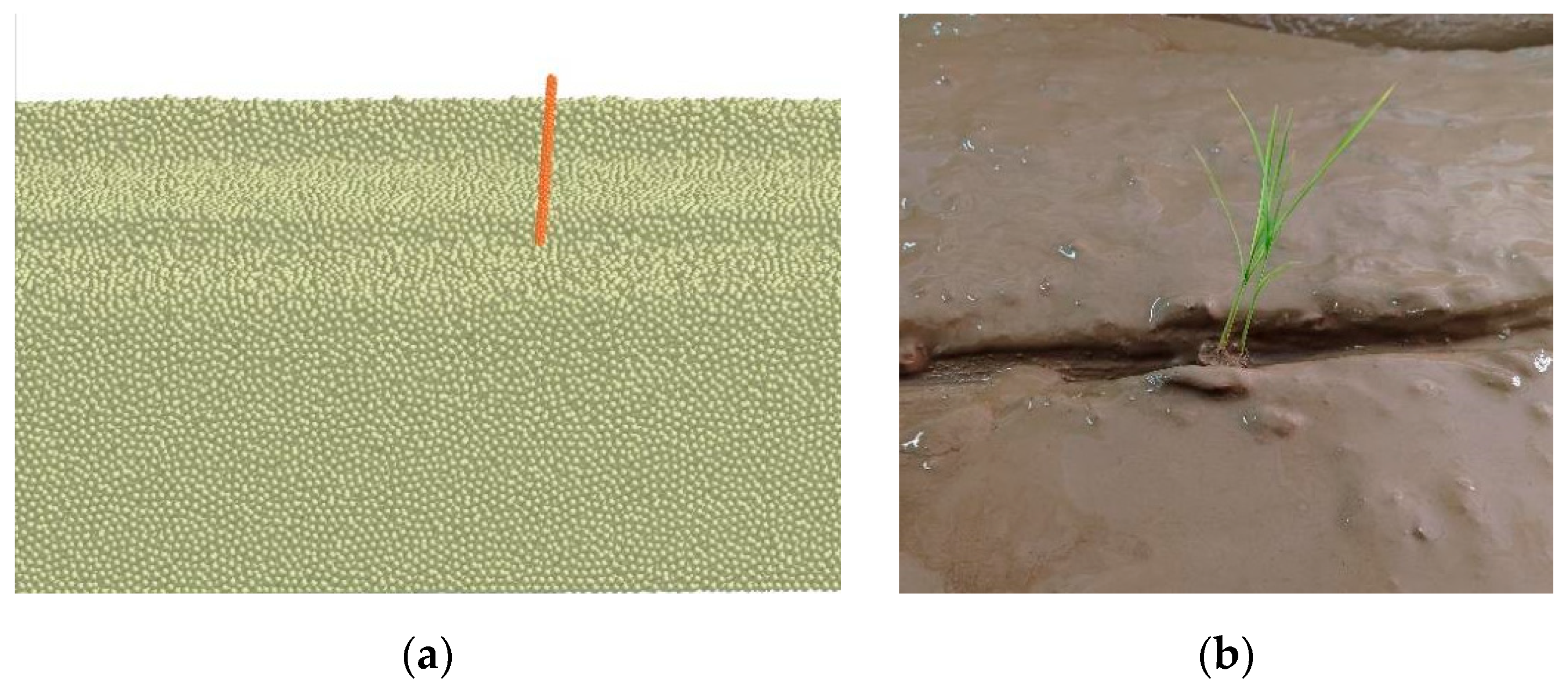
By comparing the results of the simulation test with those of the validation test, it was found that the uprightness bias of the pot seedling in the bench test and the simulation test was the same, as shown in
Figure 16. And the relative error between the actual value and the simulation value is less than 5%, and the rice seedling has a high degree of uprightness after falling into the trench in the test, and the lateral and longitudinal degree of uprightness can reach about 70°.
4. Discussion
The basic principle of seedling throwers is to let the pot seedling fall into the field by its own gravity. In this process, the falling attitude of the seedling and the soil backfilling state have a significant impact on the planting effect [
26]. Nowadays, there is a problem of low pot seedling uprightness with commercially available seedling throwers, and at present, research on seedling throwers mostly focuses on the macroscopic level, meaning that understanding of the mechanism of machinery–soil–pot seedling interactions in the process of rice planting and the observation of soil reflux dynamics are also still problematic [
2,
3,
4,
5].
In this study, EDEM discrete element simulation software was used as a platform, which can accurately simulate the flow characteristics of soil and can also set up the falling attitude of the pot seedling, so that the pot seedling is not restricted by space and time during the falling process [
12,
13,
14,
15]. Based on the above advantages, a more in-depth study on the effect of pot seedling throwing uprightness can be carried out.
From the relative error of 0.85% between the simulation and the actual test two-layer soil model collapse, it can be seen that the constructed soil model can simulate the field soil. When the furrow opener opens the furrow, the furrow soil backfilling shows the three-stage evolution law of “backfilling-covering-stabilizing”, which is due to the flow characteristics of the soil after the furrow opener, resulting in the movement of the soil to heal the furrow pattern. When the falling speed of the pot seedling was 3.5 m/s, the soil backfilling period was 0–0.15 s when falling into the trench, and the advancing speed was 0.8 m/s, the horizontal and vertical uprightness of pot seedling after falling into the trench could reach 67.0 ± 1.2° and 65.2 ± 1.5°. This is because, with the quicker falling speed and faster movement into the trench, both sides of the soil rapidly return to cover the stage, thus hindering the pot seedling’s left and right tilt; at the same time, the slower forward speed will lead to a smaller tilt angle of pot seedlings in the longitudinal direction. With a furrow opener width of 40 mm, depth of 37.87 mm, and body length of 32.32 mm, the pot seedling could achieve 70.0 ± 1.0° lateral uprightness and 69.4 ± 0.8° longitudinal uprightness. This is because the narrow grooves all support the pot seedlings in the vertical direction, increasing the left and right clamping forces hindering pot seedling sink and lateral offset; different-depth grooves’ soil mobility is not the same, because soil mobility at different depths is not consistent; and the longer the length of the furrow opener, the longer the soil reflux time and the slower its dynamic clamping effect. In the above results, although rice pot seedling uprightness has a better effect, the results are based on the simulation test and bench test, and there is still a more significant difference compared to real field operation.
In order to further improve rice potting uprightness, future research will focus on the following aspects:
- (1)
Consider the effect of field-specific conditions on pot seedling throwing. In order to further study the quality of pot seedling throwing, further research is needed to take into account the influence of soil changes in paddy fields and rice stubble in the field.
- (2)
Research on soil furrow openers in paddy fields. Although a V-type furrow opener is proposed in this study, its furrow opening effect is affected by different soil environments, and its adaptability needs to be further improved.
- (3)
Research on furrow-opening and seedling-supporting devices for planting implements. Although the furrow opener can improve the uprightness of rice pot seedlings, adding a seedling support device can further improve the uprightness of pot seedlings.
5. Conclusions
In this study, a coupling model of the furrow opener–soil–pot seedling system was constructed based on the discrete element method, with contact parameters calibrated to verify its accuracy, and the experiment was carried out using the method of synergistic analysis of soil backfilling dynamics and upright planting of rice pot seedlings, which provided an accurate simulation and analysis of the falling process of pot seedlings throwing and optimized the soil opener in paddy fields, providing a guide to improve the uprightness of pot seedling throwing. The main conclusions are as follows:
- (1)
The mechanism of open furrow soil backfilling is revealed: the open furrow disturbance is concentrated in the edge region, and the return process is divided into three stages—backfilling (0–0.15 s), covering (0.15–0.30 s), and stabilizing (>0.30 s), which realize the migration of particles, accumulation, and the fixation of furrow shape, respectively.
- (2)
Analysis of pot seedlings into the soil: lateral clamping force and longitudinal impact force together reduce the total torque to zero, where the optimal operating parameters of 3.5 m/s drop speed, 0.8 m/s forward speed, and 0.15 s drop time difference achieve lateral and longitudinal uprightness of 67.0 ± 1.2° and 65.2 ± 1.5°, respectively.
- (3)
Optimize the structural parameters of the furrow opener: when the width of the furrow opener is 40 mm, the depth is 37.87 mm, and the length of the body is 32.32 mm, the degree of uprightness is improved to 70.0 ± 1.0° (lateral) and 69.4 ± 0.8° (longitudinal).
- (4)
Model validation: the error between bench test and simulation results is <5%, and the optimized uprightness of the pot seedling has a significant increase compared to the standard of pot seedling uprightness during throwing (uprightness > 30°), which confirms the reliability of the model and provides theoretical support for the design and parameter regulation of high-speed rice-planting equipment.
Author Contributions
Conceptualization, B.J., J.C., L.X. and J.L. (Jinlong Lin); formal analysis, B.J., J.C., X.C., J.L. (Junan Liu) and Y.C.; methodology, L.X. and J.L. (Jinlong Lin); software, B.J. and J.C.; data curation, B.J., J.C., L.X. and J.L. (Jinlong Lin); writing—original draft preparation, B.J., J.C, L.X, J.L. (Jinlong Lin), J.L. (Junan Liu), Y.C. and X.C.; writing—review and editing, X.C., L.X. and J.L. (Jinlong Lin); project administration, L.X. and J.L. (Jinlong Lin); funding acquisition, L.X. and J.L. (Jinlong Lin). All authors have read and agreed to the published version of the manuscript.
Funding
This research was funded by the National Natural Science Foundation of China (Grant No. 52265032).
Institutional Review Board Statement
Not applicable.
Data Availability Statement
The data reported in this study are contained within the article.
Acknowledgments
The authors thank the editor and anonymous reviewers for providing helpful suggestions for improving the quality of this manuscript.
Conflicts of Interest
The authors declare no conflict of interest.
References
- Tian, Y.; Gong, H.; Feng, X.; Cai, Y.; Zeng, Z. Development of a model to predict the throwing trajectory of a rice seedling. Comput. Electron. Agric. 2023, 211, 108025. [Google Scholar] [CrossRef]
- Yuan, P.; Yang, Y.; Wei, Y.; Zhang, W.; Ji, Y. Design and Experimentation of Rice Seedling Throwing Apparatus Mounted on Unmanned Aerial Vehicle. Agriculture 2024, 14, 847. [Google Scholar] [CrossRef]
- Guo, B.; Chen, H.; Zhang, C.; Wei, H.; Zhang, H. Morphological and Physiological Changes in Seedling Standing and Establishment of Broadcasted Rice Seedlings. Acta Agron. Sin. 2010, 36, 1715–1724. [Google Scholar]
- Wang, S.; Wu, J.; Pan, X.; Huang, S.; Zeng, Y. Influencing factors of seedlingstanding and growth of scatered planting in double cropping rice with total straw chopped incorporation. Trans. Chin. Soc. Agric. Eng. 2018, 34, 49–57. [Google Scholar]
- Xue, K.; Gao, K.; Kuang, F.; Zhang, S.; Liao, J. Machinery-plant-paddy soil coupling model based numerical simulation method of mechanical transplanting process of big rice seedling. Comput. Electron. Agric. 2022, 198, 107053. [Google Scholar] [CrossRef]
- Song, X.; Dai, F.; Zhang, X.; Chen, H.; Zhang, F. Numerical analyses ridge-forming for whole film-mulching and double ridge-furrow, a discrete element method. Comput. Electron. Agric. 2023, 215, 108364. [Google Scholar] [CrossRef]
- Xiuli, Y.; Bin, C.; Hang, X.; Wenbin, Z.; Long, Q.I. Design and experiments of the side-deep fertilization device with sliding-knife furrow opener and pneumatic ejector for a liquid fertilizer atomizer. Trans. Chin. Soc. Agric. Eng. 2023, 39, 13–25. [Google Scholar]
- Chen, J.; Zhou, H.; Che, H.; Liu, Y.; Li, P. Optimal design of ejector belt seedling collecting mecchanism based on EDEM. Inmateh Agric. Eng. 2023, 69, 109–120. [Google Scholar] [CrossRef]
- Bai, H.; Li, X.; Zeng, F.; Su, Q.; Cui, J. Calibration and experiments of the simulation bonding parameters for plug seedling substrate block. Inmateh Agric. Eng. 2023, 69, 617–625. [Google Scholar] [CrossRef]
- Zeng, F.; Li, X.; Bai, H.; Cui, J.; Liu, X. Calibration of the discrete element parameters and experimental validation of the oil sunflower plug seedling pots. Inmateh Agric. Eng. 2022, 68, 629–640. [Google Scholar] [CrossRef]
- Li, J.; Liu, X.; Zou, L.; Yuan, J.; Du, S. Analysis of the interaction between end-effectors, soil and asparagus during a harvesting process based on discrete element method. Biosyst. Eng. 2020, 196, 127–144. [Google Scholar] [CrossRef]
- Zhao, Z.; Hou, J.; Guo, P.; Xia, C.; Yan, H. Analysis of Soil–Straw Movement Behavior in Saline–Alkali Soil Under Dual-Axis Rotary Tillage Based on EDEM. Agriculture 2025, 15, 337. [Google Scholar] [CrossRef]
- Jiang, S.; Chen, B.; Jiang, H.; Guo, P.; Wang, X. Simulation and Evaluation of the Performance of Pneumatic Residual Film Recycler Comb Teeth. Agriculture 2025, 15, 811. [Google Scholar] [CrossRef]
- Wang, Z.; You, Y.; Zhang, X.; Wang, D.; Pan, C. Bionic Optimal Design and Performance Study of Soil Loosening Shovels for Degraded Grasslands. Agriculture 2025, 15, 487. [Google Scholar] [CrossRef]
- Qiao, Y.; Huang, S.; Yang, C.; Liu, S.; Wang, K. Calibration and Testing of Discrete Element Simulation Parameters for Ultrasonic Vibration-Cutter-Soil Interaction Model. Acta Agron. Sin. 2025, 15, 20. [Google Scholar] [CrossRef]
- Zhu, D.; Shi, M.; Yu, C.; Yu, Z.; Kuang, F. Tool-straw-paddy soil coupling model of mechanical rotary-tillage process based on DEM-FEM. Comput. Electron. Agric. 2023, 215, 108410. [Google Scholar] [CrossRef]
- Lin, J.; Liao, Q.; Wang, X.; Kang, Y.; Du, W. Exploring straw movement through the simulation of shovel-type seedbed preparation machine-straw-soil interaction using the DEM-MBD coupling method. Comput. Electron. Agric. 2024, 226, 109465. [Google Scholar] [CrossRef]
- Wan, L.; Li, Y.; Liu, Z.; Song, J.; Dong, X. Study on behavior rules of the licorice-soil-licorice oscillating harvester coupled system using numerical method. Comput. Electron. Agric. 2024, 226, 109479. [Google Scholar] [CrossRef]
- Wang, X.; Zhang, S.; Pan, H.; Zheng, Z.; Huang, Y. Effect of soil particle size on soil-subsoiler interactions using the discrete element method simulations. Biosyst. Eng. 2019, 182, 138–150. [Google Scholar] [CrossRef]
- Cai, J.; Liu, M.; Xiao, L.; Lin, J.; Ye, Y. Design and Experiment of Transplanting Device with Variable Row-spacing of Rice Potted-seedling Transplanter. Trans. Chin. Soc. Agric. Mach. 2020, 51, 50–59. [Google Scholar]
- Makange, N.R.; Ji, C.; Torotwa, I. Prediction of cutting forces and soil behavior with discrete element simulation. Comput. Electron. Agric. 2020, 179, 105848. [Google Scholar] [CrossRef]
- Wang, J.; Xu, Y.; Wang, C.; Xiang, Y.; Tang, H. Design and simulation of a trenching device for rice straw burial and trenching based on MBD-DEM. Comput. Electron. Agric. 2023, 207, 107722. [Google Scholar] [CrossRef]
- Chen, D.; Xu, Y.; Song, Y.; Xin, M.; Wu, L. A Bionic Walking Wheel for Enhanced Trafficability in Paddy Fields with Muddy Soil. Biomimetics 2024, 9, 68. [Google Scholar] [CrossRef] [PubMed]
- Wang, T.; Chen, X.; Liu, J. Calbration of Discerete Element Parameters for Soil Surface Mud in Mechanical Direct Seeding of Rice. Acta Agric. Univ. Jiangxiensis 2024, 46, 232–240. [Google Scholar]
- He, X.; Ma, S.; Liu, Z.; Wang, D.; Shang, S. Calibration and Testing of Saline Soil Parameters Based on EDEM Discrete Element Methods. Inmateh Agric. Eng. 2024, 73, 2. [Google Scholar]
- Zhong, P.; Jia, W.; Yang, W.; He, J.; Zhang, E. Calibration and Testing of Parameters for the Discrete Element Simulation of Soil Particles in Paddy Fields. Agriculture 2024, 14, 118. [Google Scholar] [CrossRef]
- Roessler, T.; Katterfeld, A. DEM parameter calibration of cohesive bulk materials using a simple angle of repose test. Particuology 2019, 45, 105–115. [Google Scholar] [CrossRef]
- Ma, C.; Yi, S.; Tao, G. A rotary blade design for paddy fields with long rice straw based on EDEM. Eng. Agrícola 2023, 43, e20220062. [Google Scholar] [CrossRef]
Figure 1.
Rice mechanical throwing planting system.
Figure 1.
Rice mechanical throwing planting system.
Figure 2.
Movement of seedling guide cylinders at rice potting plants. (a) Schematic of YOZ plane motion; (b) schematic of XOZ plane motion.
Figure 2.
Movement of seedling guide cylinders at rice potting plants. (a) Schematic of YOZ plane motion; (b) schematic of XOZ plane motion.
Figure 3.
Pot seedlings into the soil top view.
Figure 3.
Pot seedlings into the soil top view.
Figure 5.
Modeling process.
Figure 5.
Modeling process.
Figure 6.
Draw plate method test. (a) Practical tests; (b) simulation test.
Figure 6.
Draw plate method test. (a) Practical tests; (b) simulation test.
Figure 7.
Determination of stacking angle θ and slump h.
Figure 7.
Determination of stacking angle θ and slump h.
Figure 8.
Verification process.
Figure 8.
Verification process.
Figure 9.
Pot seedlings falling test. (a) The actual soil penetration test; (b) simulated soil penetration test.
Figure 9.
Pot seedlings falling test. (a) The actual soil penetration test; (b) simulated soil penetration test.
Figure 10.
Situation of pot seedling uprightness. (a) Lateral uprightness of pot seedlings; (b) longitudinal uprightness of pot seedlings.
Figure 10.
Situation of pot seedling uprightness. (a) Lateral uprightness of pot seedlings; (b) longitudinal uprightness of pot seedlings.
Figure 11.
Bench test set. (a) Three-dimensional diagram of bench test device: 1. rack; 2. screw; 3. seedling tube; 4. conveyor belt; 5. floating plate; and 6. ditcher. (b) Test bench.
Figure 11.
Bench test set. (a) Three-dimensional diagram of bench test device: 1. rack; 2. screw; 3. seedling tube; 4. conveyor belt; 5. floating plate; and 6. ditcher. (b) Test bench.
Figure 4.
Rice Pot seedlings stressed into the ground. (a) Schematic of YOZ plane motion; (b) schematic of XOZ plane motion.
Figure 4.
Rice Pot seedlings stressed into the ground. (a) Schematic of YOZ plane motion; (b) schematic of XOZ plane motion.
Figure 12.
Soil disturbance.
Figure 12.
Soil disturbance.
Figure 13.
Experiments on the effect of detached attitude on the uprightness of pot seedlings; (a) the change in seedling uprightness under different falling speeds; (b) the change in seedling erectness under different forward speeds; (c) the change in seedling uprightness under different soil reflux times.
Figure 14.
Experiment on the effect of furrow opener structural parameters on the uprightness of pot seedlings. (a) The change in seedling erectness under different widths of the furrow opener; (b) the change in seedling erectness under different furrow opener depths; (c) the change in seedling erectness under different furrow opener body length.
Figure 15.
Interaction between structural parameters of furrow opener. (a) LK-LS; (b) LK-LS; (c) LK-LC; (d) LK-LC; (e) LS-LC; (f) LS-LC.
Figure 15.
Interaction between structural parameters of furrow opener. (a) LK-LS; (b) LK-LS; (c) LK-LC; (d) LK-LC; (e) LS-LC; (f) LS-LC.
Figure 16.
Comparison chart of bench test results. (a) Simulated bench test results; (b) actual bench test results.
Figure 16.
Comparison chart of bench test results. (a) Simulated bench test results; (b) actual bench test results.
Table 1.
Simulation parameters of the soil.
Table 1.
Simulation parameters of the soil.
| 0–20 mm Soil Parameters | Value | 20–60 mm Soil Parameters | Value |
|---|
| Soil Poisson’s ratio | 0.300 | Soil Poisson’s ratio | 0.300 |
| Shear modulus of soil, MPa | 0.832 | Shear modulus of soil, MPa | 4.331 |
| Soil–soil recovery coefficient | 0.055 | Soil–soil recovery coefficient | 0.055 |
| Soil–soil static friction coefficient | 0.150 | Soil–soil static friction coefficient | 0.150 |
| Soil–soil dynamic friction coefficient | 0.125 | Soil–soil dynamic friction coefficient | 0.125 |
| Soil–soil surface energy, J/m2 | 0.020 | Soil–soil surface energy, J/m2 | 0.098 |
| Soil–ABS recovery coefficient | 0.350 | Soil–ABS recovery coefficient | 0.350 |
| Soil–ABS static friction coefficient | 0.300 | Soil–ABS static friction coefficient | 0.300 |
| Soil–ABS dynamic friction coefficient | 0.450 | Soil–ABS dynamic friction coefficient | 0.450 |
| Soil–ABS surface energy, J/m2 | 1.250 | Soil–ABS surface energy, J/m2 | 0.501 |
Table 2.
Potting soil–soil contact parameters.
Table 2.
Potting soil–soil contact parameters.
| 0–20 mm Soil and Potting Soil | Value | 20–60 mm Soil and Potting Soil | Value |
|---|
Soil–potting soil restoration
coefficient | 0.095 | Soil–potting soil restoration
coefficient | 0.040 |
Soil–potting soil static friction
coefficient | 0.178 | Soil–potting soil static friction
coefficient | 0.157 |
Soil–potting soil dynamic friction
coefficient | 0.121 | Soil–potting soil dynamic friction coefficient | 0.113 |
Soil–potting soil surface
energy, J/m2 | 0.064 | Soil– potting soil surface
energy, J/m2 | 0.064 |
Table 3.
Attitude test factor-level table.
Table 3.
Attitude test factor-level table.
| Number | Experimental Factors |
|---|
| Falling Speed/v2 (m/s) | Forward Speed/v1 (m/s) | Soil Backfilling Time/T (s) |
|---|
| 1 | 2.5 | 0.8 | 0–0.15 |
| 2 | 3.0 | 1.0 | 0.15–0.30 |
| 3 | 3.5 | 1.2 | 0.30–0.45 |
Table 4.
Level table of structural parameter factors of furrow opener.
Table 4.
Level table of structural parameter factors of furrow opener.
| Number | Experimental Factors |
|---|
Furrow Opener Width
/LK (mm) | Furrow Opener Depth
/LS (mm) | Furrow Opener Body Length
/LC (mm) |
|---|
| 1 | 40 | 30 | 25 |
| 2 | 50 | 40 | 50 |
| 3 | 60 | 50 | 75 |
| 4 | - | - | 100 |
Table 5.
Orthogonal simulation test results and analysis table.
Table 5.
Orthogonal simulation test results and analysis table.
| Number | Factor | Lateral
Uprightness (°) | Longitudinal
Uprightness (°) |
|---|
| v2 (m/s) | v1 (m/s) | T (s) |
|---|
| 1 | 1 (2.5) | 1 (0.8) | 1 (0–0.15) | 72.66 | 62.76 |
| 2 | 1 | 2 (1.0) | 2 (0.15–0.30) | 70.63 | 59.90 |
| 3 | 1 | 3 (1.2) | 3 (0.30–0.45) | 71.70 | 51.01 |
| 4 | 2 (3.0) | 1 | 2 | 73.67 | 66.38 |
| 5 | 2 | 2 | 3 | 71.90 | 64.3 |
| 6 | 2 | 3 | 1 | 71.14 | 61.61 |
| 7 | 3 (3.5) | 1 | 3 | 72.52 | 68.24 |
| 8 | 3 | 2 | 1 | 74.36 | 64.88 |
| 9 | 3 | 3 | 2 | 70.85 | 61.44 |
Lateral
Uprightness (°) | K1 | 214.99 | 218.85 | 218.16 | | |
| K2 | 216.71 | 216.89 | 215.15 | | |
| K3 | 217.73 | 213.69 | 216.12 | | |
| R | 2.74 | 5.16 | 3.01 | | |
Longitudinal
Uprightness (°) | K1 | 173.67 | 197.38 | 189.25 | | |
| K2 | 192.29 | 189.08 | 187.72 | | |
| K3 | 194.56 | 174.06 | 183.55 | | |
| R | 20.89 | 23.32 | 5.7 | | |
Table 6.
Orthogonal simulation test and results.
Table 6.
Orthogonal simulation test and results.
| Number | Experimental Factors | Lateral Uprightness
(°) | Longitudinal Uprightness
(°) |
|---|
| LK | LS | LC |
|---|
| 1 | 0 (50) | −1 (30) | −1 (25) | 70.11 | 68.12 |
| 2 | 0 | −1 | 1 (75) | 66.86 | 61.12 |
| 3 | −1 (40) | 0 (40) | 1 | 66.61 | 67.54 |
| 4 | 1 (60) | −1 | 0 (50) | 66.11 | 65.62 |
| 5 | 0 | 1 (50) | 1 | 63.61 | 63.01 |
| 6 | 1 | 1 | 0 | 64.64 | 63.87 |
| 7 | 0 | 1 | −1 | 68.75 | 63.34 |
| 8 | −1 | 1 | 0 | 68.06 | 68.08 |
| 9 | 0 | 0 | 0 | 67.88 | 68.06 |
| 10 | −1 | −1 | 0 | 69.16 | 66.15 |
| 11 | 1 | 0 | −1 | 67.48 | 66.7 |
| 12 | −1 | 0 | −1 | 70.17 | 68.25 |
| 13 | 0 | 0 | 0 | 68.21 | 67.97 |
| 14 | 1 | 0 | 1 | 63.03 | 63.81 |
| 15 | 0 | 0 | 0 | 68.31 | 69.4 |
| Disclaimer/Publisher’s Note: The statements, opinions and data contained in all publications are solely those of the individual author(s) and contributor(s) and not of MDPI and/or the editor(s). MDPI and/or the editor(s) disclaim responsibility for any injury to people or property resulting from any ideas, methods, instructions or products referred to in the content. |
© 2025 by the authors. Licensee MDPI, Basel, Switzerland. This article is an open access article distributed under the terms and conditions of the Creative Commons Attribution (CC BY) license (https://creativecommons.org/licenses/by/4.0/).


 ,
, 


