
Residual Film–Cotton Stubble–Nail Tooth Interaction Study Based on SPH-FEM Coupling in Residual Film Recycling

Abstract
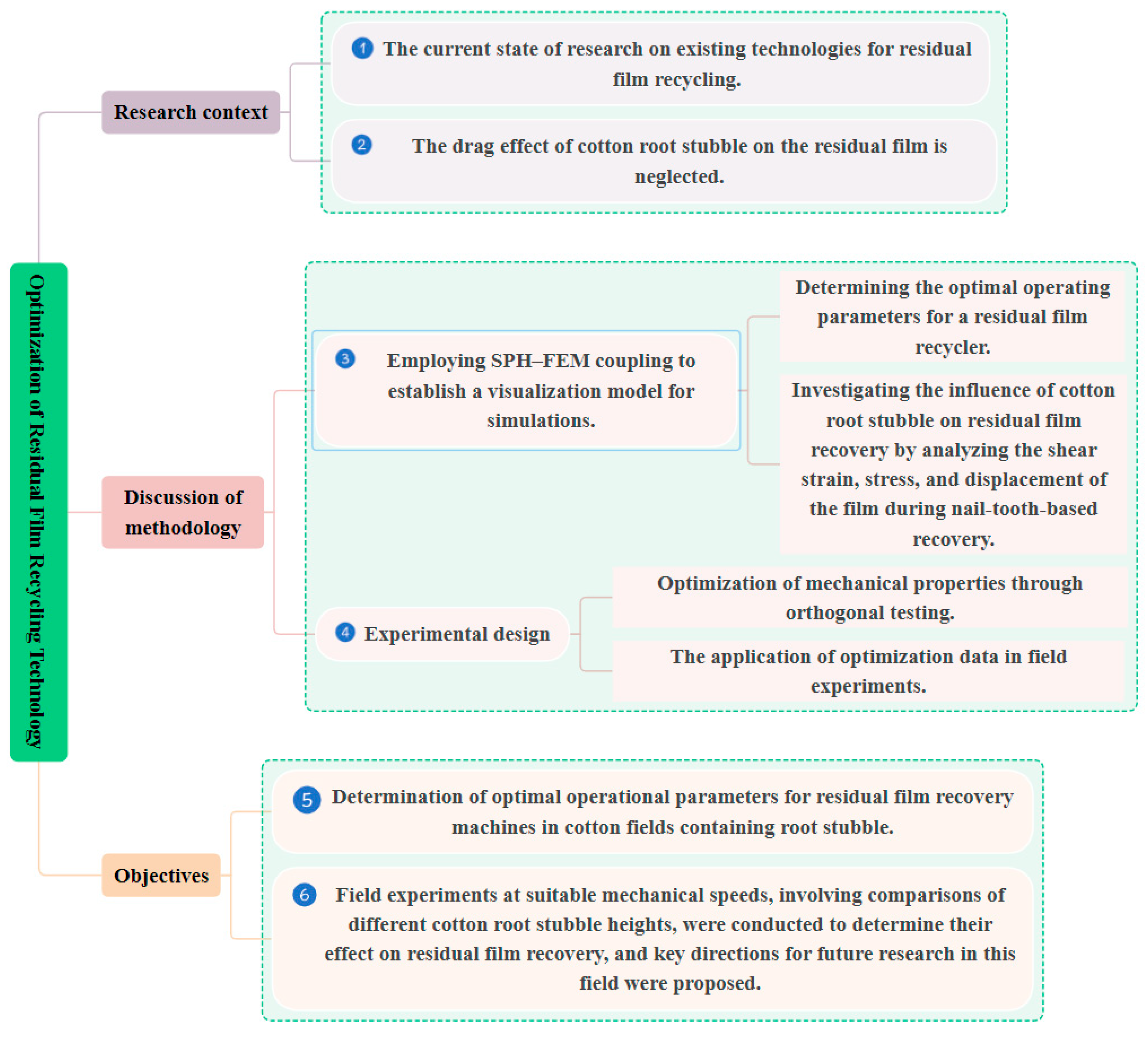
1. Introduction
- (1)
- Research purpose: Existing residual film recycling technology focuses on mechanical performance, ignoring the dragging effect of cotton stubble on residual film. To determine whether the influence of stubble on residual film recycling exists, the mechanical parameters are optimized as much as possible to reduce the impact of cotton stubble on residual film recycling and improve the recycling rate.
- (2)
- Research tasks: In order to optimize the model more conveniently and intuitively, this study adopts the popular SPH (smooth particle hydrodynamics)-FEM (finite element method) coupling algorithm to establish a dynamic interaction model of nail teeth, residual film, soil and cotton stubble, and the effects of cotton stubble on the residual film were analyzed by accurately simulating the shear strain, stress and upward displacement of the residual film during residual film recycling. By optimizing the motion parameters of the nail teeth, the maximum shear strain, pickup height and average peak stress were 1293, 363.81 mm and 3.42 MPa, respectively, which reduced the influence of root stubble on residual film recovery.
- (3)
- Target results: Through multifactorial orthogonal testing, the optimal operational parameters were identified as a 6.7 km/h forward velocity, a 5.5 r/s rotational speed, and a 30° soil entry angle. Combined with field experiments, the effects of 5–8 cm and 8–14 cm root stubble on the residual film recovery rate were compared. It was confirmed that the effect of cotton root stubble on residual film recovery could be reduced under appropriate machine operating parameters. This provides strong support and a theoretical and practical basis for future research on the correlation between root stubble and residual film and how to improve the residual film recovery rate.
2. Overall Structure and Analysis of Key Components
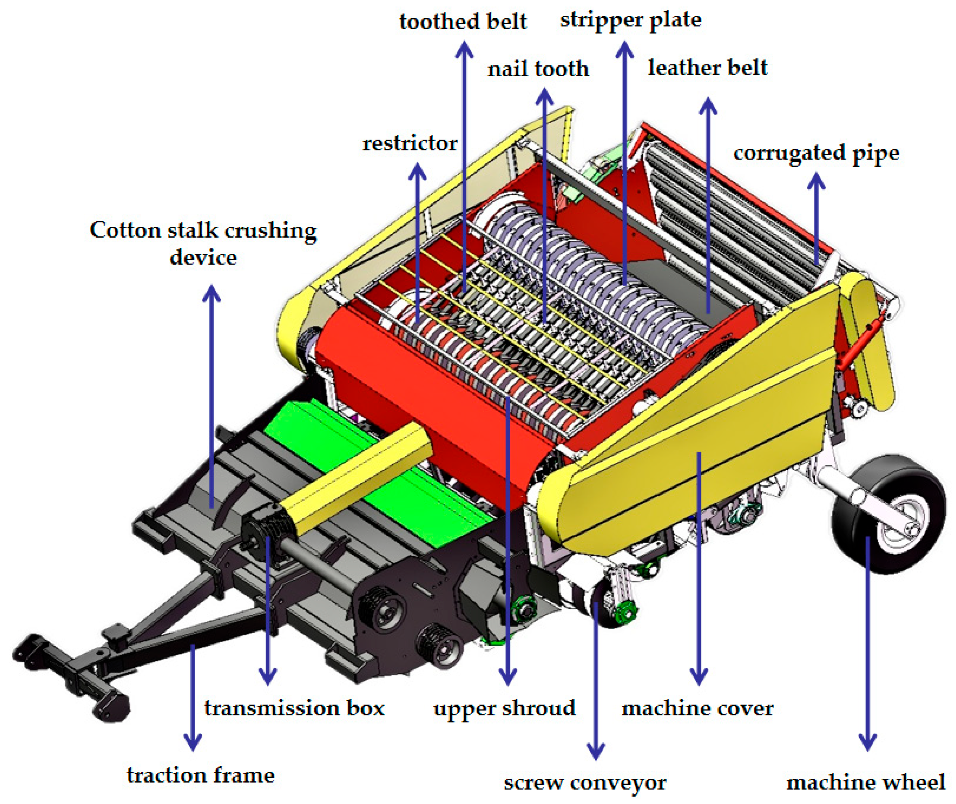
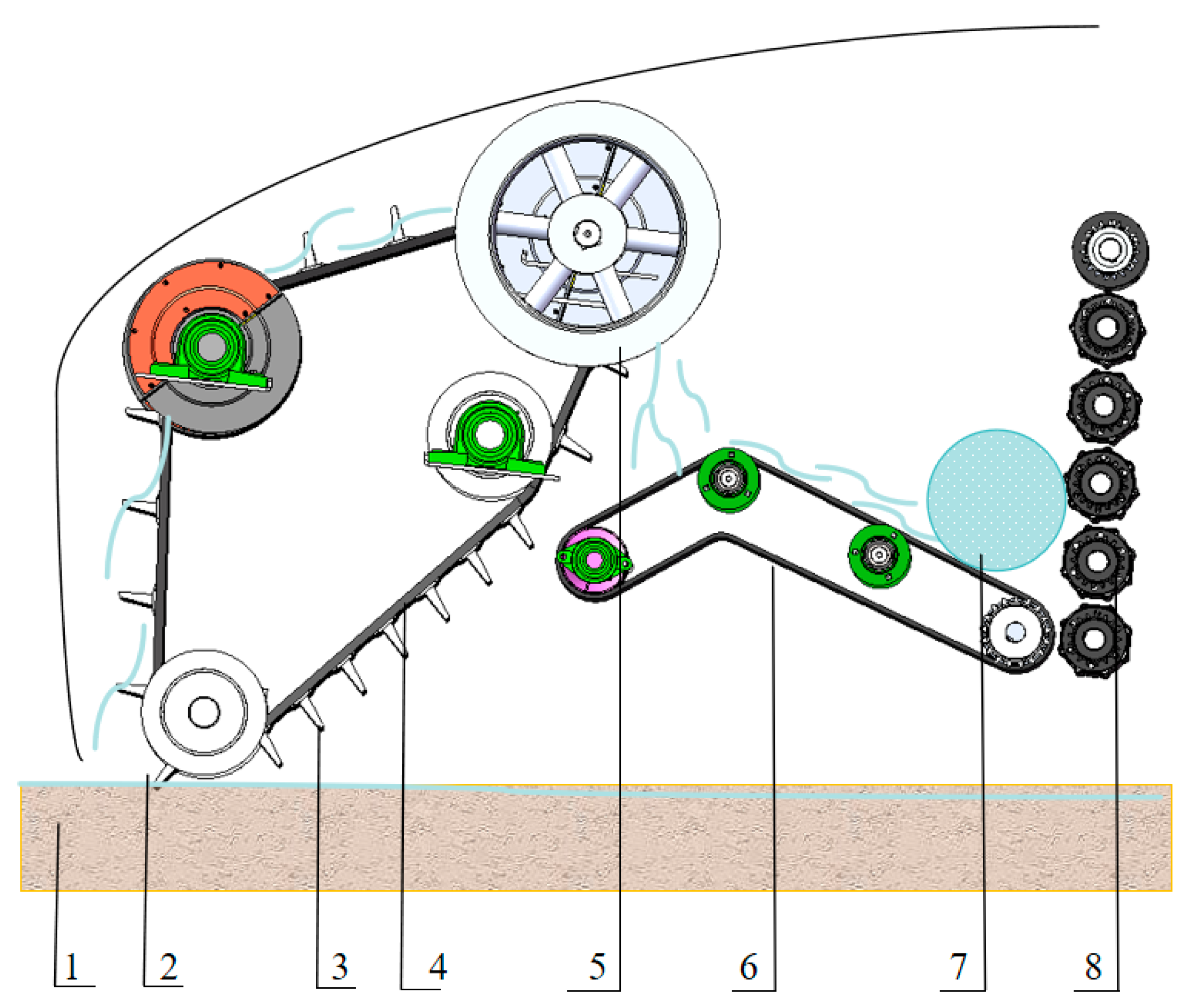
2.1. Overall Structure of Residual Film Recycling Machine
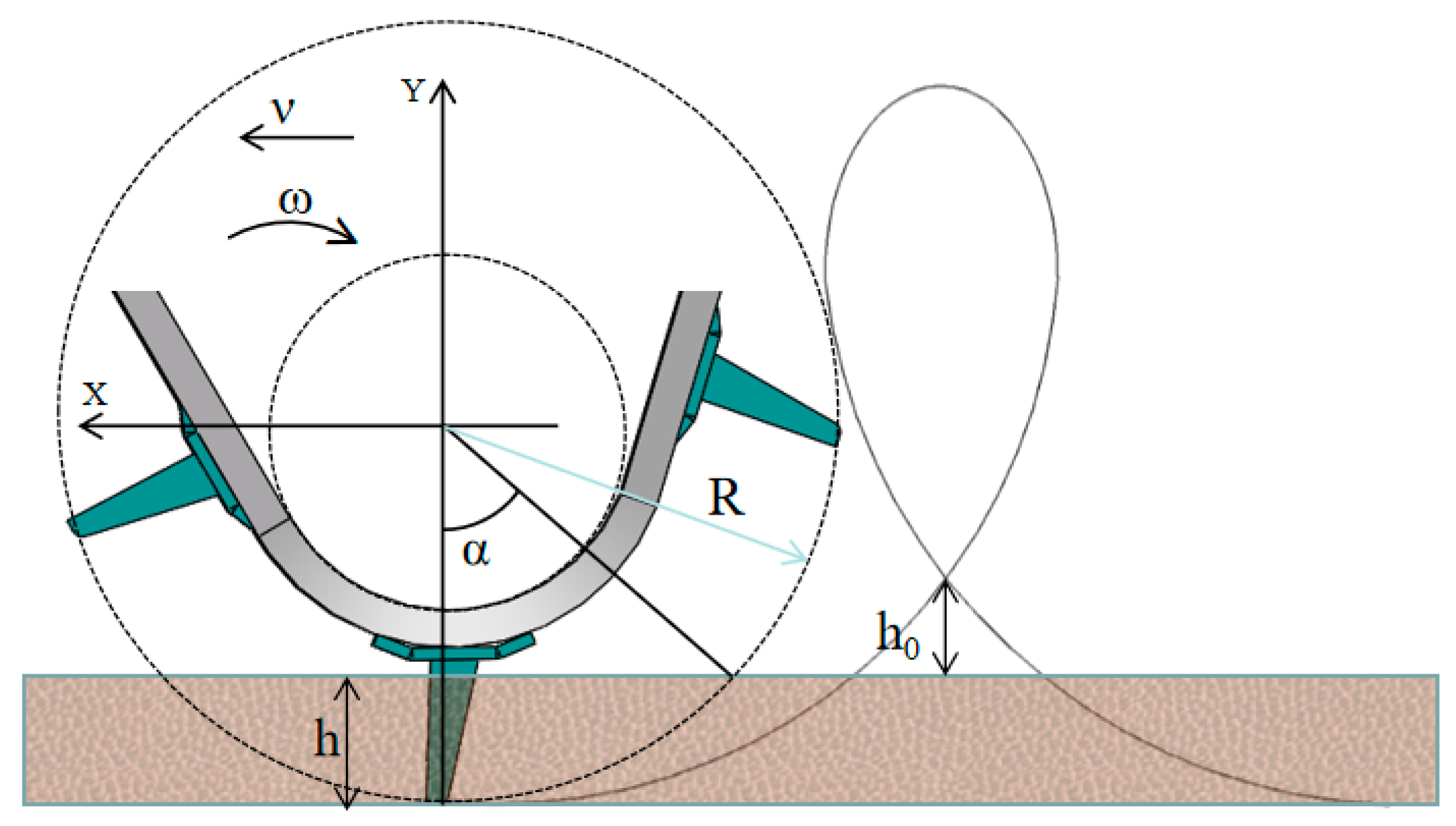
2.2. Force Analysis of Membrane Pickup Nail Teeth
2.3. The Parameters of the Motion of the Nail Teeth
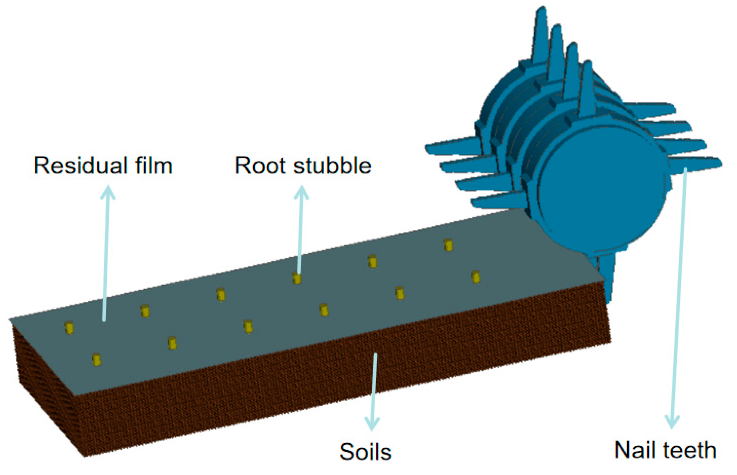
3. Simulation Model Parameter Establishment Method
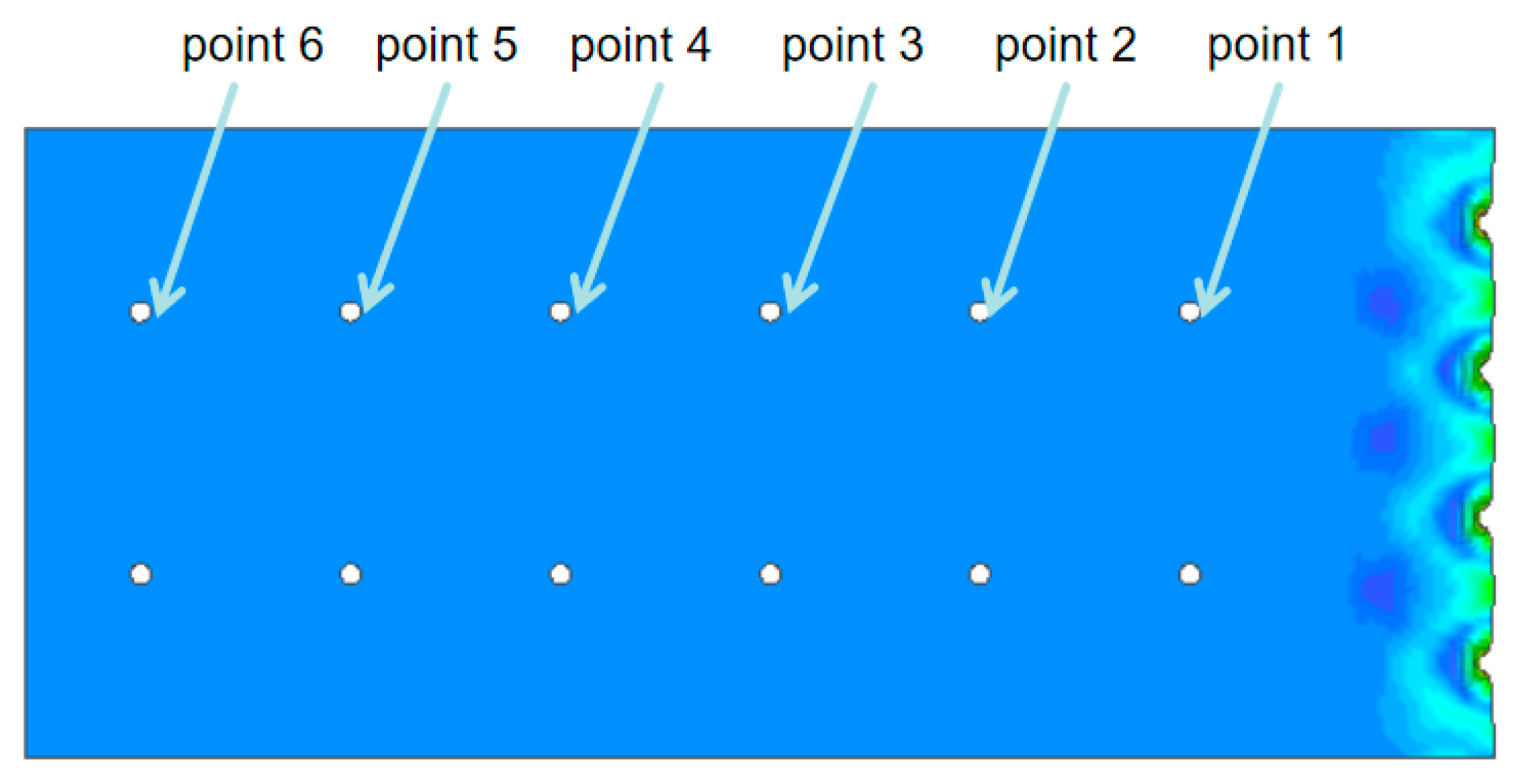
Setting of Model Boundary Conditions
4. Simulation Analysis
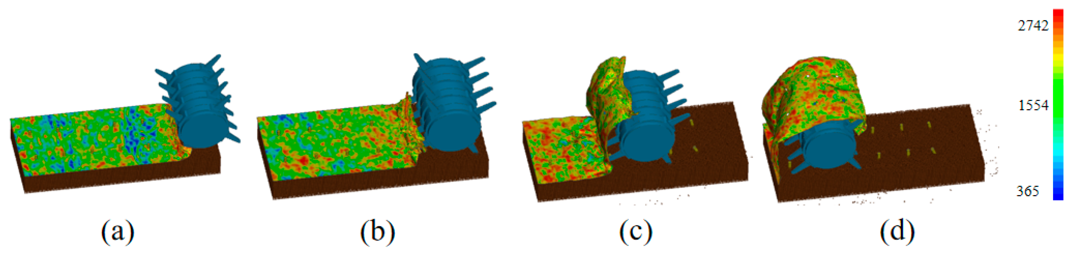
4.1. Simulation of Dynamic Properties
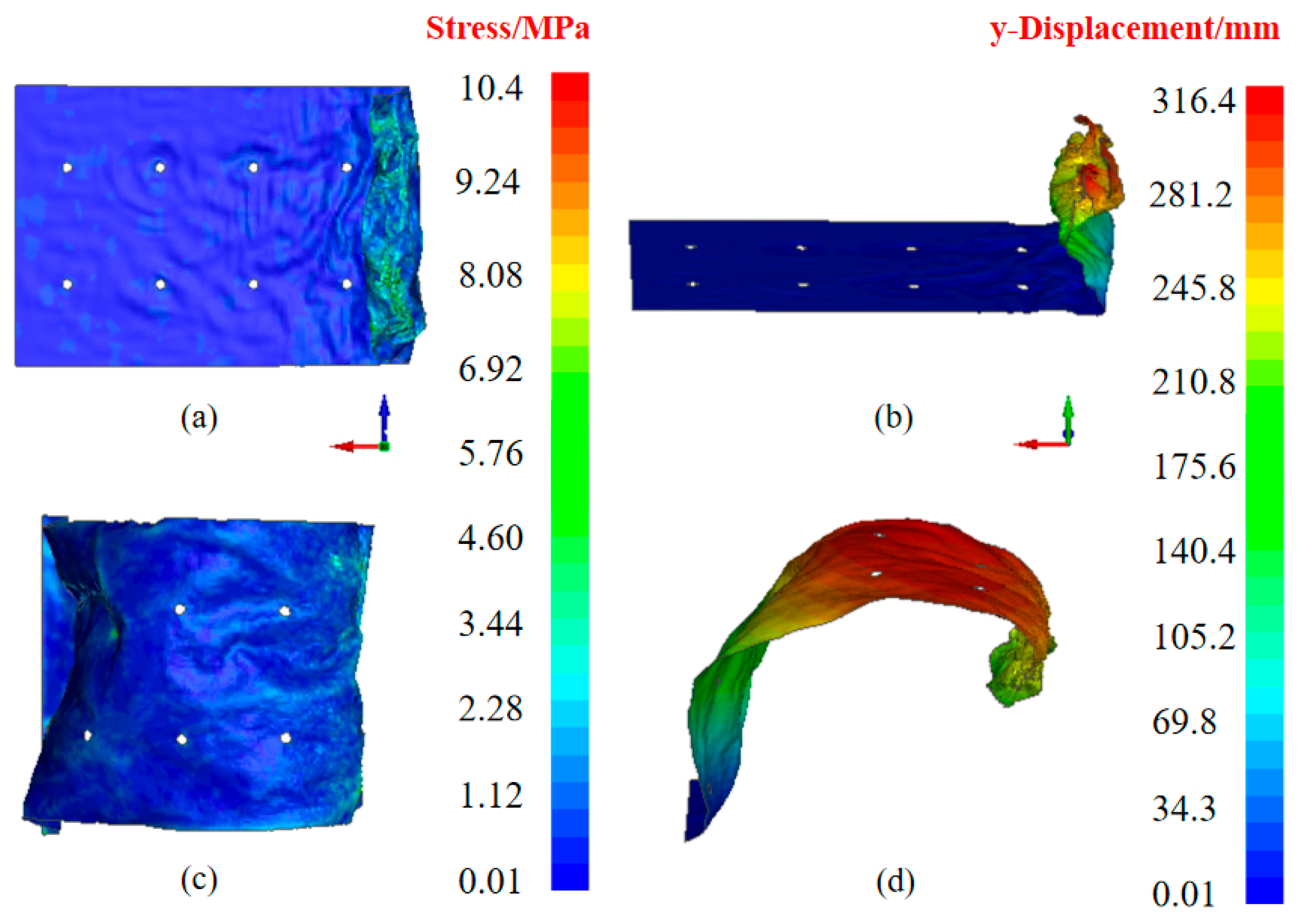
4.2. Residual Film Peak Stress and Maximum Deformation
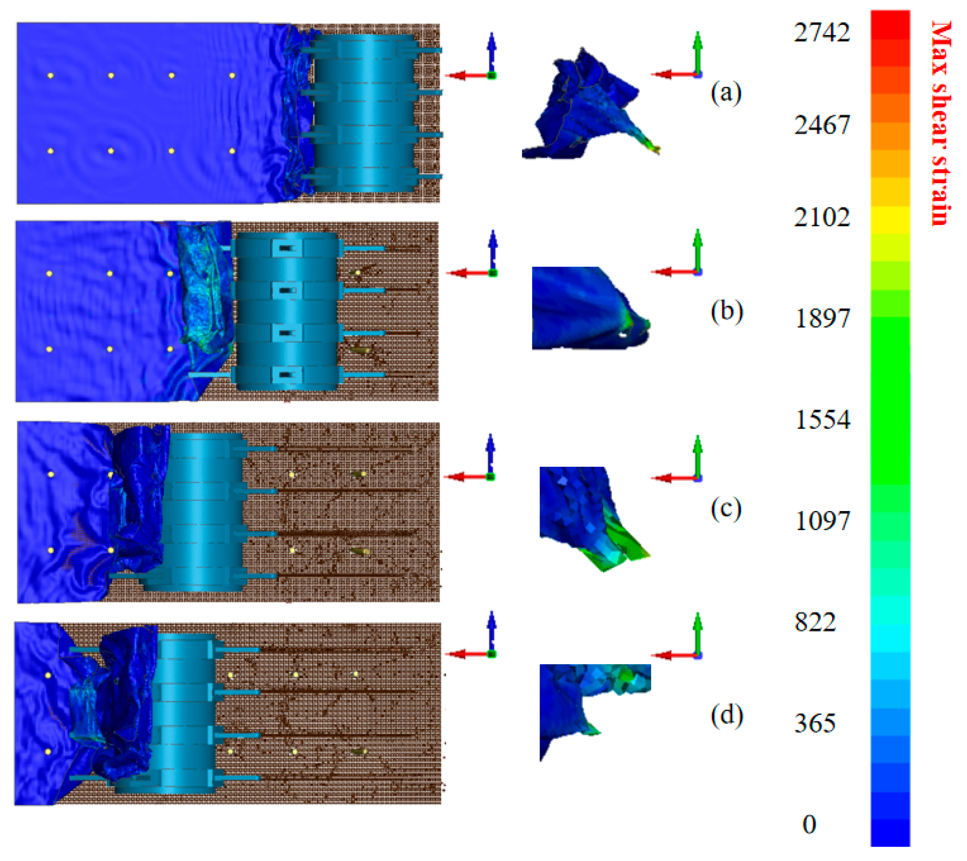
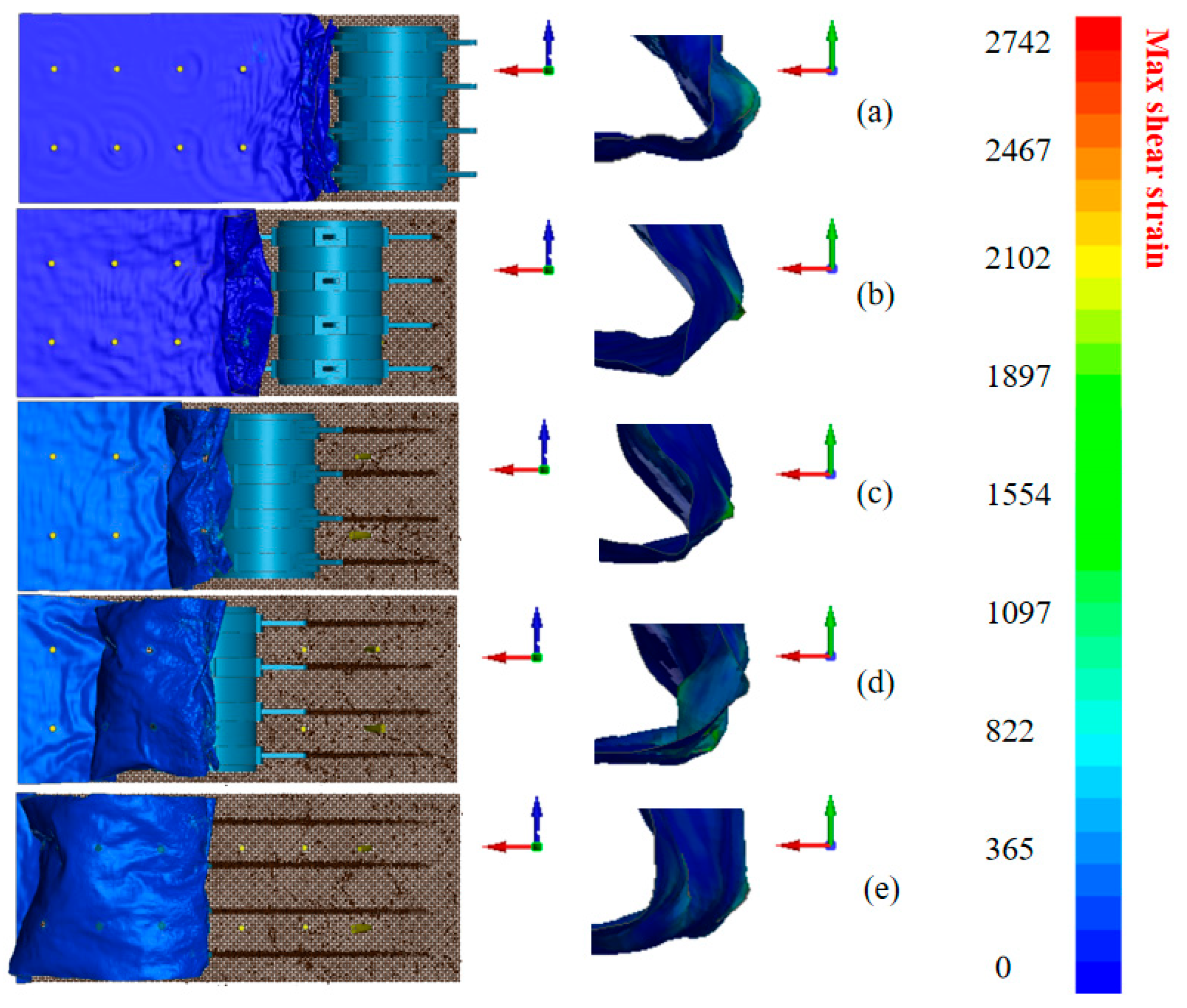
4.3. Maximum Shear Strain of Residual Film
5. Multifactor Simulation Optimization Test
5.1. Analysis of Test Results
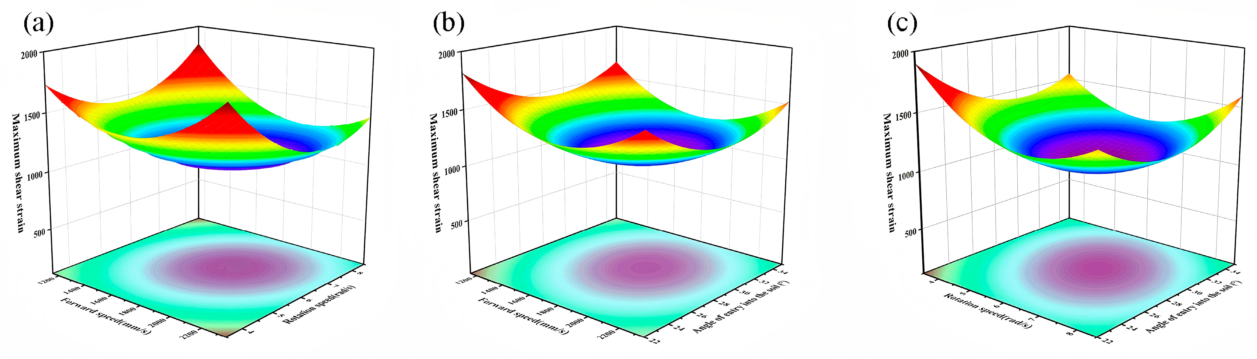
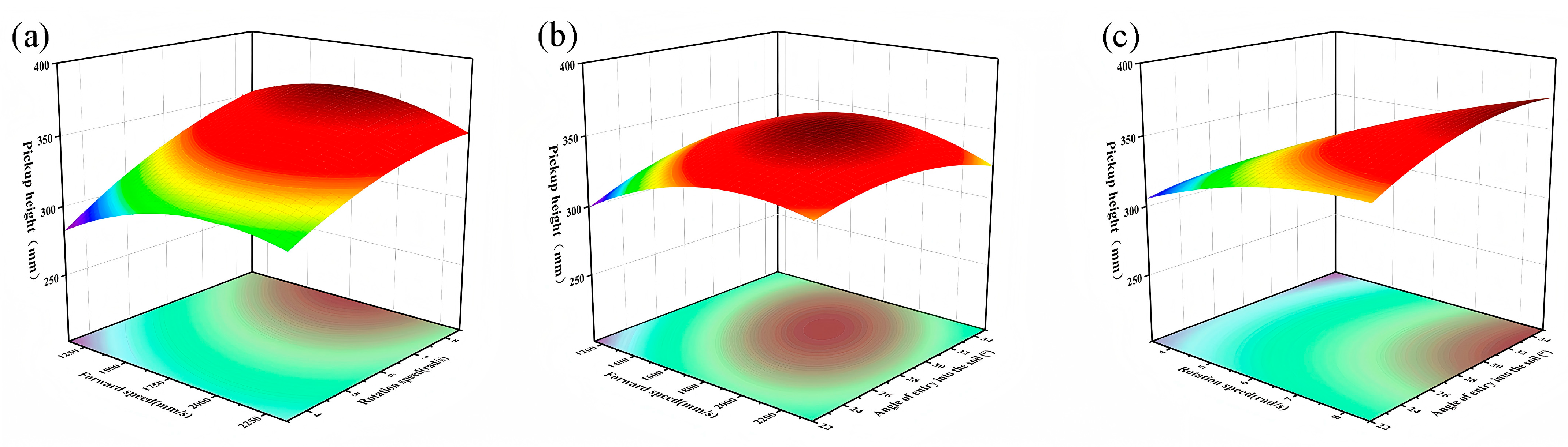
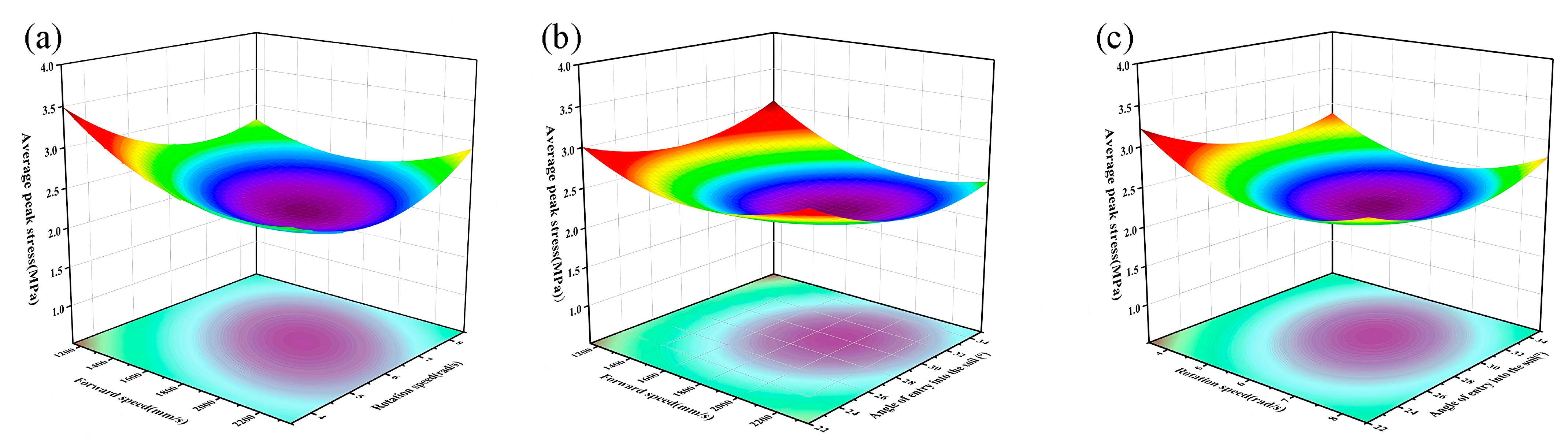
5.2. Response Surface Analysis
5.3. Optimization
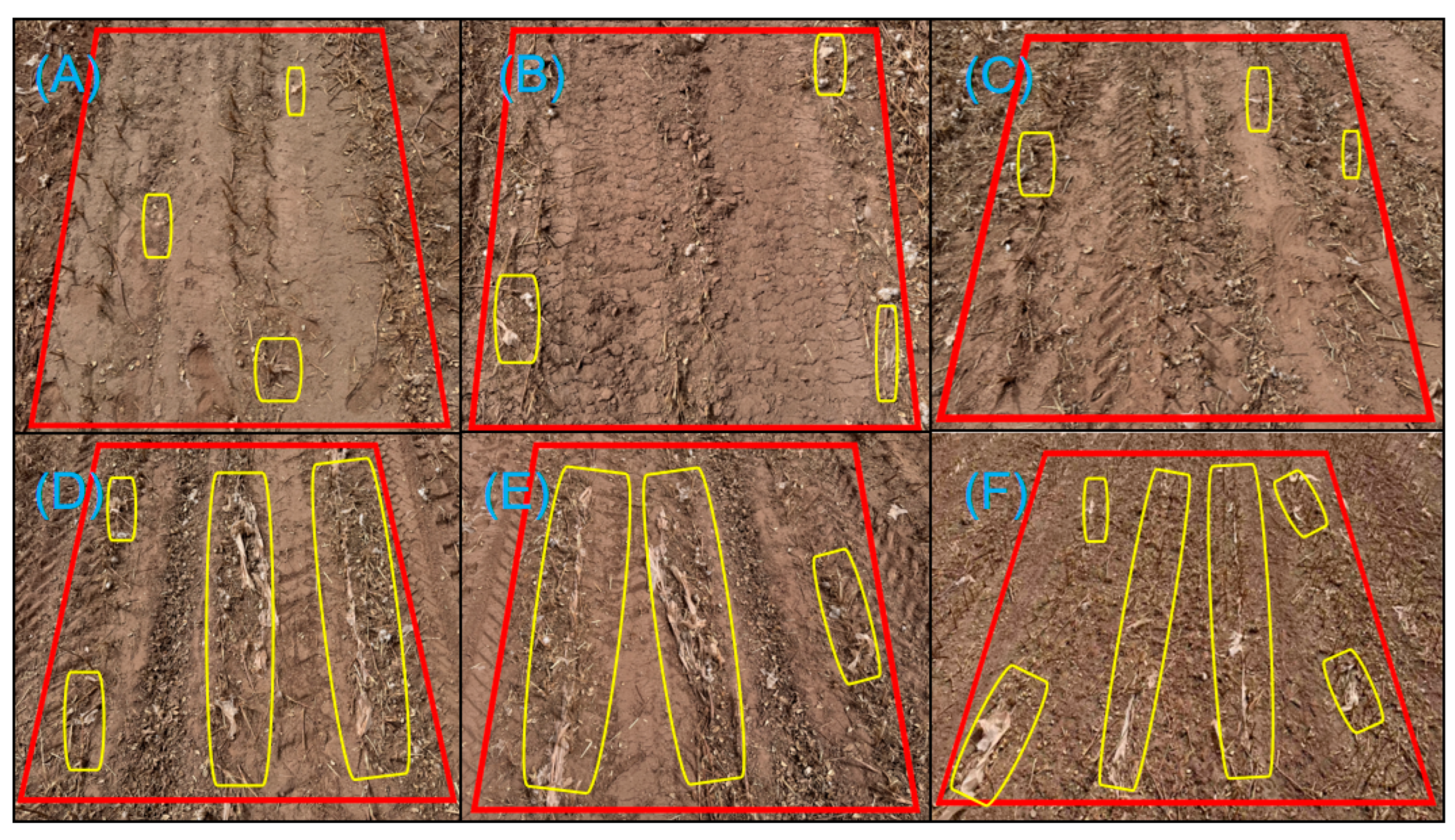
6. Field Trials
6.1. Test Condition
6.2. Experimental Design and Analysis of Results
6.3. Comparison of Past Studies
7. Summary
Author Contributions
Funding
Institutional Review Board Statement
Data Availability Statement
Conflicts of Interest
References
- Yan, C.; Liu, E.; Shu, F.; Liu, Q.; Liu, S.; He, W. Review of agricultural plastic mulching and its residual pollution and prevention measures in China. J. Agric. Resour. Environ. 2014, 31, 95–102. [Google Scholar]
- Chen, Q.; Wu, C.; Chen, G.; Li, Z. The effect of the different overlay on growth and yield of spring peanut. J. Guangxi Agric. 2013, 28, 28–30. [Google Scholar]
- He, W.; Yan, C.; Liu, S.; Chang, R.; Wang, X.; Cao, S.; Liu, Q. The use of plastic mulch film in typical cotton planting regions and the associated environmental pollution. J. Agro-Environ. Sci. 2009, 28, 1618–1622. [Google Scholar]
- Shi, Z.; Zhang, X.; Yan, J.; Jiang, Y.; Yao, J. Experiment and Analysis of Film-Soil Separation Motion Characteristics of a Chain Drive Residual Film Recovery Mechanism for the Tillage Layer. Appl. Sci. 2022, 12, 5884. [Google Scholar] [CrossRef]
- Peng, Q.; Li, K.; Wang, X.; Zhang, G.; Kang, J. Design and Test of Stripping and Impurity Removal Device for Spring-Tooth Residual Plastic Film Collector. Agriculture 2023, 13, 42. [Google Scholar] [CrossRef]
- Xue, S.; Chen, X.; Li, J.; Wang, X.; Zhang, Z. Design of and Experiment on a Film Removal Device of an Arc-Toothed Residual Film Recovery Machine before Sowing. Appl. Sci. 2021, 11, 8551. [Google Scholar] [CrossRef]
- Halquist, J. LS-DYNA Keyword User’s Manual (r:13107); Livermore Software Technology Corporation: Livermore, CA, USA, 2020. [Google Scholar]
- Jin, X.; Ma, F.; Wang, D.; Zhu, Z. Simulation of Mouldboard Plough Soil Cutting Based on Smooth Particle Hydrodynamics Method and FEM–SPH Coupling Method. Agriculture 2023, 13, 1847. [Google Scholar] [CrossRef]
- Yang, W.; Lu, H.; Xiao, X.; Luo, Z.; Dai, W.; Lu, Z. Research on the Sugarcane Stubble Chopping Mechanism of an Ultra-Deep Vertical Rotary Tillage Cutter Based on FEM-SPH Coupling Method. Agriculture 2025, 15, 329. [Google Scholar] [CrossRef]
- Wang, J.; Liu, Z.; Yang, M.; Zhou, W.; Tang, H.; Qi, L.; Wang, Q.; Wang, Y.-J. A Combined Paddy Field Inter-Row Weeding Wheel Based on Display Dynamics Simulation Increasing Weed Mortality. Agriculture 2024, 14, 444. [Google Scholar] [CrossRef]
- Huo, Y.; Zhong, Y.G.; Xin, M.; Li, S.C. Modeling and simulation of droplet impact on an elastic beam based on FEM-SPH and SPH-SPH FSI methods. Ocean. Eng. 2024, 310, 118730. [Google Scholar] [CrossRef]
- Zhang, S.; Zhao, W.; Dai, F.; Song, X.; Qu, J.; Zhang, F. Simulation Analysis and Experiment of the Compaction Process of the Full Film Double Ridge Furrow Ridging and Laminating Machine. Trans. Chin. Soc. Agric. Eng. 2020, 36, 20–30. [Google Scholar]
- Kang, J.; Li, S.; Yang, X.; Liu, L.; Li, C. Simulation Analysis and Experimental Verification of Power Consumption for Disc trenching Machine Operation. Trans. Chin. Soc. Agric. Eng. 2016, 32, 8–15. [Google Scholar]
- Zhang, Z.; Li, J.; Wang, X.; Zhao, Y.; Xue, S.; Su, Z. Parameters Optimization and Test of an Arc-Shaped Nail-Tooth Roller-Type Recovery Machine for Sowing Layer Residual Film. Agriculture 2022, 12, 660. [Google Scholar] [CrossRef]
- Xie, J.; Tang, W.; Cao, F.; Han, Y.; Zhang, Y.; Yang, Y.; Li, K. Design and Experiment of a Tooth Chain Composite Residual Film Recycling Machine. Trans. Chin. Soc. Agric. Eng. 2020, 36, 11–19. [Google Scholar]
- Gingold, R.A.; Monaghan, J.J. Smoothed particle hydrodynamics: Theory and application to non-spherical stars. Mon. Not. R. Astron. Soc. 1977, 181, 375–389. [Google Scholar] [CrossRef]
- Libersky, L.D.; Randles, P.W.; Carney, T.C.; Dickinson, D.L. Recent improvements in SPH modeling of hypervelocity impact. Int. J. Impact Eng. 1997, 20, 525–532. [Google Scholar] [CrossRef]
- Gray, J.P.; Monaghan, J.J.; Swift, R. SPH elastic dynamics. Comput. Methods Appl. Mech. Eng. 2001, 190, 6641–6662. [Google Scholar] [CrossRef]
- Yosef, T.Y.; Fang, C.; Faller, R.K.; Kim, S.; Bielenberg, R.W.; Stolle, C.S. Adaptive coupling of fem and sph method for simulating dynamic post-soil interaction under impact loading. Adv. Eng. Softw. 2024, 195, 103707. [Google Scholar] [CrossRef]
- Peng, C.; Zhang, W.; Islam, M.R. Large deformation analysis of geomaterials using stabilized total Lagrangian smoothed particle hydrodynamics. Eng. Anal. Bound. Elem. 2022, 136, 252–265. [Google Scholar]
- Liang, R.; Chen, X.; Jiang, P.; Zhang, B.; Meng, H.; Peng, X.; Kan, Z. Calibration of The Simulation Parameters of The Particulate Materials in Film Mixed Materials. Int. J. Agric. Biol. Eng. 2020, 13, 29–36. [Google Scholar] [CrossRef]
- Wang, X.; Hu, H.; Wang, Q.; Li, H.; He, J.; Chen, W. Calibration Method of Soil Contact Characteristic Parameters Based on DEM Theory. Trans. Chin. Soc. Agric. Mach. 2017, 48, 78–85. [Google Scholar]
- Zhu, Z.; Zhao, H.; Cai, Y.; Qu, J. Damage Analysis of Plastic Film Under Hail Impact. Trans. Chin. Soc. Agric. Eng. 2022, 38, 246–253. [Google Scholar]
- Dai, F.; Song, X.; Zhao, W.; Zhang, F.; Ma, H.; Ma, M. Simulative Calibration on Contact Parameters of Discrete Elements for Covering Soil on Whole Plastic Film residual on Double Ridge. Trans. Chin. Soc. Agric. Mach. 2019, 50, 49–56, 77. [Google Scholar]
- Yang, Y.; Wen, B.; Ding, L.; Li, L.; Chen, X.; Li, J. Soil particle modeling and parameter calibration for use with discrete element method. Trans. ASABE 2021, 64, 2011–2023. [Google Scholar] [CrossRef]
- Zhang, X.; Guo, L.; Yan, J.; Shi, Z.; Kang, M.; Yao, J. Simulation Analysis and Parameter Optimization of Residual Film Pickup Process Based on Finite Element Method. Agriculture 2024, 14, 524. [Google Scholar] [CrossRef]
- Fu, W.E.; Chang, Y.Q.; He, B.C.; Wu, L.C. Determination of Young’s modulus and Poisson’s ratio of thin films by X-ray methods. Thin Solid Film. 2013, 544, 201–205. [Google Scholar] [CrossRef]
- Zhang, S.; Zhao, X.; Wang, X.; Dong, J.; Zhao, P.; Yang, F.; Chen, X.; Liu, F.; Huang, Y. Discrete element modeling and shear properties of the maize stubble-soil complex. Comput. Electron. Agric. 2023, 204, 107–519. [Google Scholar] [CrossRef]
- Ma, L.; Wang, P.; Yang, X.; Li, J.; Li, X.; Li, X. Design and Experiment of a Vibration Type Root Cutting Device for Fruit Trees. J. Trans. Chin. Soc. Agric. Mach. 2020, 51, 281–291. [Google Scholar]
- Chen, L.; Liang, X.; Cao, C. Virtual Simulation and Power Consumption Testing of Straw Returning Machine Based on Multibody Dynamics. Trans. Chin. Soc. Agric. Mach. 2016, 47, 106–111. [Google Scholar]
- Yang, W.; Xiao, X.; Pan, R.; Guo, S.; Yang, J. Numerical Simulation of Spiral Cutter-Soil Interaction in Deep Vertical Rotary Tillage. Agriculture 2023, 13, 1850. [Google Scholar] [CrossRef]
- GB/T 25412-2010; Residual Film Recycling Machine. China Standards Press: Beijing, China, 2010.
- GB/T14290-2021; Round Straw Baling Machine. China Standards Press: Beijing, China, 2021.
- Xie, J.; Hou, S.; Zhang, X.; Zhang, T. Analysis and Experiment on the Contact of Spring Tooth Picking up Film Based on the Mechanical Properties of Residual Film. J. Agric. Mech. Res. 2016, 38, 177–181. [Google Scholar]
- Cao, S.; Xie, J.; Wang, H.; Yang, Y.; Zhang, Y.; Zhou, J.; Wu, S. Design and Operating Parameters Optimization of the Hook-and-Tooth Chain Rail Type Residual Film Picking Device. Agriculture 2022, 12, 1717. [Google Scholar] [CrossRef]


| Structure | Density (kg/m3) | Elastic Modulus (MPa) | Poisson’s Ratio |
|---|---|---|---|
| Residual film | 1030 | 0.66 | 0.34 |
| Soil | 1660 | 7.2 | 0.38 |
| Root stubble | 1250 | 0.0012 | 0.34 |
| Nail teeth | 7850 | 2.1 × 10⁵ | 0.30 |
| Code | Forward Speed of Nail Teeth X1/(mm/s) | Rotation Speed of Nail Teeth X2/(r/s) | Entry Angle of Nail Teeth X3/(°) |
|---|---|---|---|
| −1.682 | 740.92 | 1.80 | 17.57 |
| −1 | 1150.00 | 3.50 | 22.00 |
| 0 | 1750.00 | 6.00 | 28.50 |
| 1 | 2350.00 | 8.50 | 35.00 |
| 1.682 | 2759.08 | 10.20 | 39.43 |
| No. | Forward Speed of Nail Teeth, X1 (mm/s) | Rotation Speed of Nail Teeth, X2 (r/s) | Entry Angle of Nail Teeth, X3 (°) | Maximum Shear Strain of Residual Film, Y1 | Pickup Height of Residual Film, Y2 (mm) | Mean Peak Stress of Residual Film, Y3 (MPa) |
|---|---|---|---|---|---|---|
| 1 | −1.000 | −1.000 | −1.000 | 2146 | 256.3 | 3.95 |
| 2 | 1.000 | −1.000 | −1.000 | 2345 | 315 | 3.28 |
| 3 | −1.000 | 1.000 | −1.000 | 2075 | 323.2 | 3 |
| 4 | 1.000 | 1.000 | −1.000 | 1592 | 320.3 | 3.35 |
| 5 | −1.000 | −1.000 | 1.000 | 1773 | 282.2 | 3.68 |
| 6 | 1.000 | −1.000 | 1.000 | 1895 | 275.2 | 2.66 |
| 7 | −1.000 | 1.000 | 1.000 | 2004 | 359.8 | 3.19 |
| 8 | 1.000 | 1.000 | 1.000 | 1698 | 349.7 | 2.96 |
| 9 | −1.682 | 0.000 | 0.000 | 2237 | 290.1 | 3.45 |
| 10 | 1.682 | 0.000 | 0.000 | 1935 | 307.8 | 3.04 |
| 11 | 0.000 | −1.682 | 0.000 | 2154 | 280.6 | 3.59 |
| 12 | 0.000 | 1.682 | 0.000 | 1932 | 366.2 | 3.21 |
| 13 | 0.000 | 0.000 | −1.682 | 1945 | 305.4 | 3.14 |
| 14 | 0.000 | 0.000 | 1.682 | 1836 | 328.1 | 3.05 |
| 15 | 0.000 | 0.000 | 0.000 | 935 | 350.9 | 2.13 |
| 16 | 0.000 | 0.000 | 0.000 | 1002 | 343.5 | 2.15 |
| 17 | 0.000 | 0.000 | 0.000 | 1164 | 352.4 | 2.26 |
| 18 | 0.000 | 0.000 | 0.000 | 1125 | 358.9 | 2.38 |
| 19 | 0.000 | 0.000 | 0.000 | 1006 | 346.3 | 2.19 |
| 20 | 0.000 | 0.000 | 0.000 | 977 | 340.5 | 2.2 |
| Source | DOF | Maximum Shear Strain of Residual Film, Y1 | Pickup Height of Residual Film, Y2 (mm) | ||||
|---|---|---|---|---|---|---|---|
| Sum of Squares | F | Significant Level, p | Sum of Squares | F | Significant Level, p | ||
| Model | 9 | 4.16 | 38.88 | <0.0001 ** | 19,373.40 | 31.90 | <0.0001 ** |
| X1 | 1 | 69,736.68 | 5.87 | 0.0359 * | 343.26 | 5.09 | 0.0477 * |
| X2 | 1 | 99,100.56 | 8.34 | 0.0162 * | 9930.29 | 147.17 | <0.0001 ** |
| X3 | 1 | 69,082.79 | 5.81 | 0.0366 * | 596.76 | 8.84 | 0.0140 * |
| X1X2 | 1 | 1.54 | 12.96 | 0.0048 * | 523.26 | 7.76 | 0.0193 * |
| X1X3 | 1 | 1250.00 | 0.11 | 0.7524 | 664.30 | 9.85 | 0.0106 * |
| X2X3 | 1 | 92,020.50 | 7.74 | 0.0194 * | 798.00 | 11.83 | 0.0063 * |
| X12 | 1 | 1.72 | 144.67 | <0.0001 ** | 4537.91 | 67.26 | <0.0001 ** |
| X22 | 1 | 1.57 | 132.22 | <0.0001 ** | 1193.57 | 17.69 | 0.0018 * |
| X32 | 1 | 1.10 | 92.56 | <0.0001 ** | 1889.94 | 28.01 | 0.0004 * |
| Residual | 10 | 1.19 | 674.73 | ||||
| Lack of fit | 5 | 78,794.59 | 1.97 | 0.2376 | 452.13 | 2.03 | 0.2276 |
| Pure error | 5 | 40,034.83 | 222.59 | ||||
| Cor total | 19 | 4.28 | 20,048.13 | ||||
| Average Peak Stress of Residual Film, Y3 (MPa) | ||||
|---|---|---|---|---|
| Source | DOF | Sum of Squares | F | Significant Level, p |
| Model | 9 | 5.86 | 56.34 | <0.0001 ** |
| X1 | 1 | 0.37 | 32.32 | 0.0002 * |
| X2 | 1 | 0.21 | 18.49 | 0.0016 * |
| X3 | 1 | 0.11 | 9.76 | 0.0108 * |
| X1X2 | 1 | 0.41 | 35.41 | 0.0001 * |
| X1X3 | 1 | 0.11 | 9.35 | 0.0121 * |
| X2X3 | 1 | 0.06 | 5.15 | 0.0467 * |
| X12 | 1 | 1.79 | 154.72 | <0.0001 ** |
| X22 | 1 | 2.39 | 206.58 | <0.0001 ** |
| X32 | 1 | 1.29 | 111.65 | <0.0001 ** |
| Residual | 10 | 0.12 | ||
| Lack of fit | 5 | 0.07 | 1.79 | 0.2696 |
| Pure error | 5 | 0.04 | ||
| Cor total | 19 | 5.98 | ||
| No. | 1 | 2 | 3 | 4 | 5 | Average Value |
|---|---|---|---|---|---|---|
| Original residual film content in the ground (g) | 176 | 182.5 | 188.3 | 177.4 | 181.7 | 181.18 |
| Residual film content in 5–8 cm root stubble area (g) | 18.9 | 19.1 | 21.3 | 16.7 | 18.3 | 18.86 |
| Content of remaining residual film entangled in 5–8 cm stubble (g) | 6.4 | 7.3 | 8.1 | 6.3 | 9.0 | 7.42 |
| Residual film content in 8–14 cm root stubble area (g) | 29.4 | 33.8 | 30.1 | 34.5 | 27.5 | 31.06 |
| Content of remaining entangled residual film in 8–14 cm stubble (g) | 19.5 | 23.4 | 20.4 | 24.7 | 19.9 | 21.58 |
Disclaimer/Publisher’s Note: The statements, opinions and data contained in all publications are solely those of the individual author(s) and contributor(s) and not of MDPI and/or the editor(s). MDPI and/or the editor(s) disclaim responsibility for any injury to people or property resulting from any ideas, methods, instructions or products referred to in the content. |
© 2025 by the authors. Licensee MDPI, Basel, Switzerland. This article is an open access article distributed under the terms and conditions of the Creative Commons Attribution (CC BY) license (https://creativecommons.org/licenses/by/4.0/).
Share and Cite
Zhang, X.; Shi, Y.; Yan, J.; Yang, S.; Hou, Z.; Li, H. Residual Film–Cotton Stubble–Nail Tooth Interaction Study Based on SPH-FEM Coupling in Residual Film Recycling. Agriculture 2025, 15, 1198. https://doi.org/10.3390/agriculture15111198
Zhang X, Shi Y, Yan J, Yang S, Hou Z, Li H. Residual Film–Cotton Stubble–Nail Tooth Interaction Study Based on SPH-FEM Coupling in Residual Film Recycling. Agriculture. 2025; 15(11):1198. https://doi.org/10.3390/agriculture15111198
Chicago/Turabian StyleZhang, Xuejun, Yangyang Shi, Jinshan Yan, Shuo Yang, Zhaoquan Hou, and Huazhi Li. 2025. "Residual Film–Cotton Stubble–Nail Tooth Interaction Study Based on SPH-FEM Coupling in Residual Film Recycling" Agriculture 15, no. 11: 1198. https://doi.org/10.3390/agriculture15111198
APA StyleZhang, X., Shi, Y., Yan, J., Yang, S., Hou, Z., & Li, H. (2025). Residual Film–Cotton Stubble–Nail Tooth Interaction Study Based on SPH-FEM Coupling in Residual Film Recycling. Agriculture, 15(11), 1198. https://doi.org/10.3390/agriculture15111198