
The Design and Testing of a New Antitangling and Antisticking Knife for a Wet Clay Soil Environment


Abstract
1. Introduction
2. Materials and Methods
2.1. Structure and Working Principle
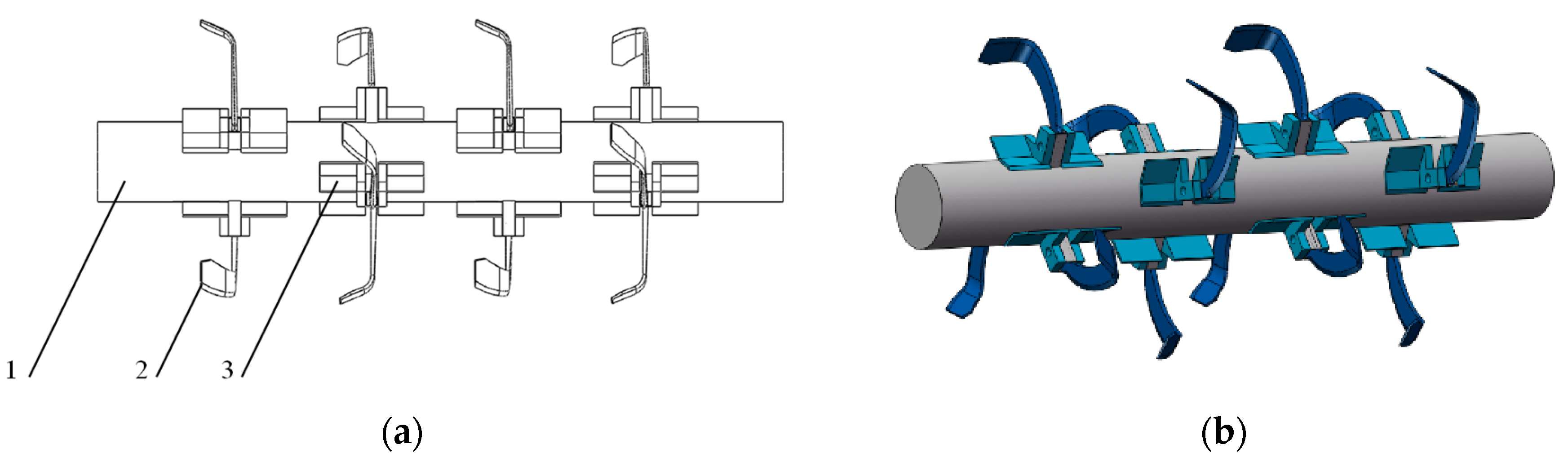
2.1.1. Structure
2.1.2. Working Principle
2.1.3. Technological Improvements
- (1)
- The tool must improve the antistalking effect. In combination with the characteristics of wet, sticky soil and rice stubble in the Jiangsu region, the use of rotary tillage knife space on both sides increases the design of the antistalking cutter, which is mainly distributed on both sides of the rotary tillage knife. Two kinds of cutters cooperate with each other in the rotary tillage knife for crushing soil and stubble breakage work. The antistalking cutter is involved in crushing soil and cutting stubble. Waste is thrown to the back of the machine tool through the back of the ramp, which does not affect the rotary tillage equipment, allowing the device to complete the crushing and antitangling of the grass. The goal of crushing and antistalking is accomplished.
- (2)
- The selection, arrangement, and structure size of rotary plow knives must be determined in order to solve the problem of entanglement. Given the gaps between rotary knives, the antistalking knives are arranged with the selected rotary knives to maximize the space between the knives, prevent the knife rollers from coming into contact with the wet and sticky soil and stubble, and thus achieve the purpose of antistalking.
2.2. Key Component Design
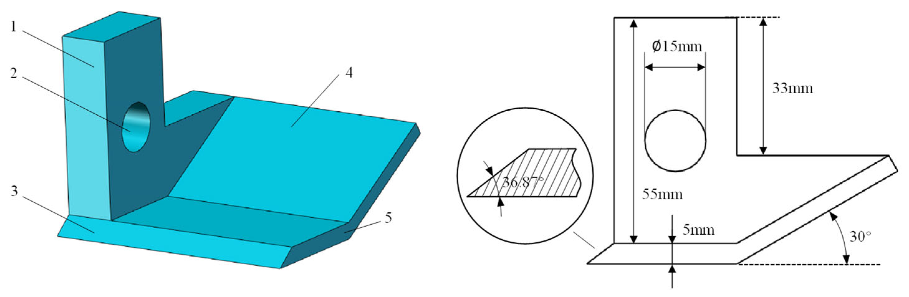
2.2.1. Antisticky Tool Design
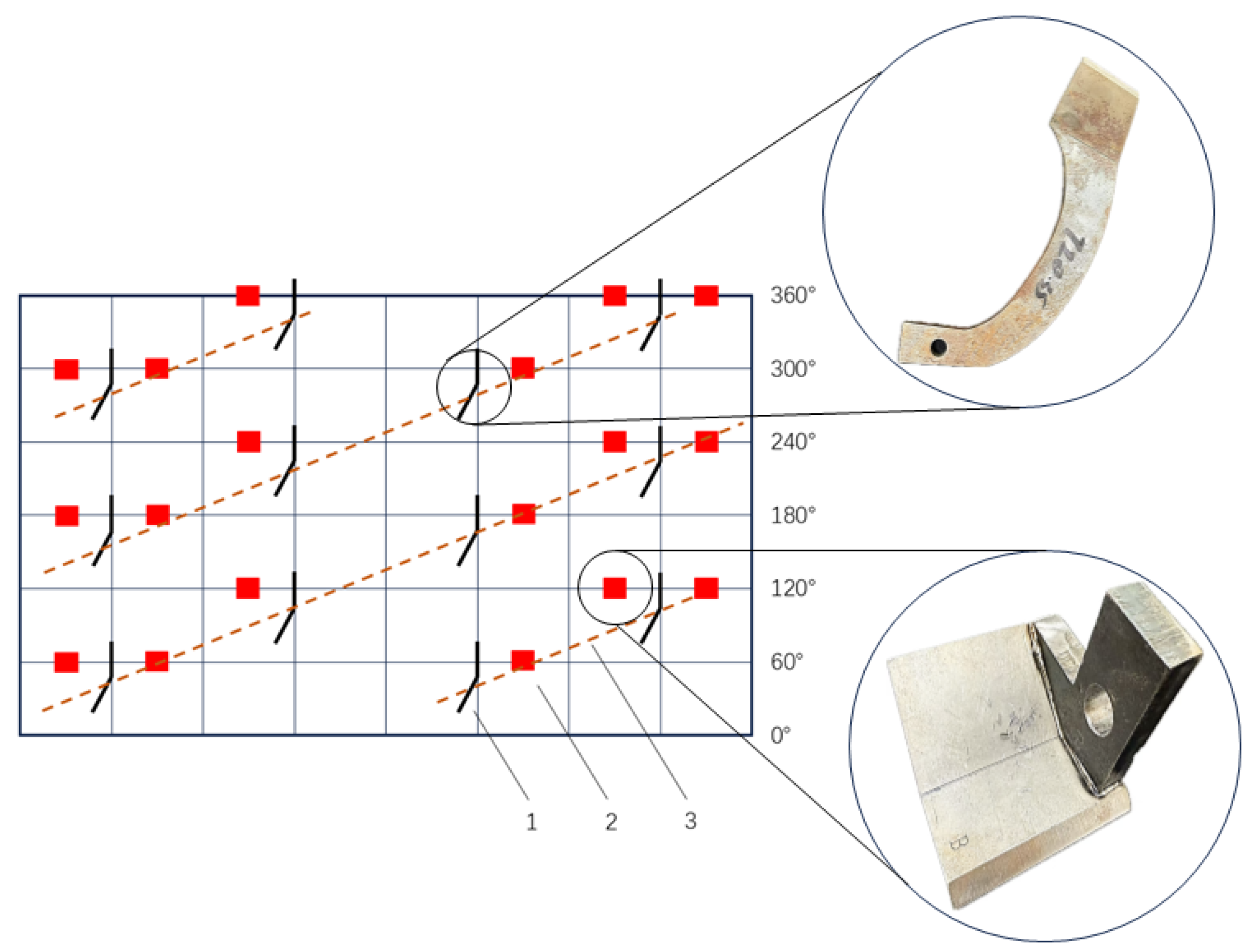
2.2.2. Tool Arrangement
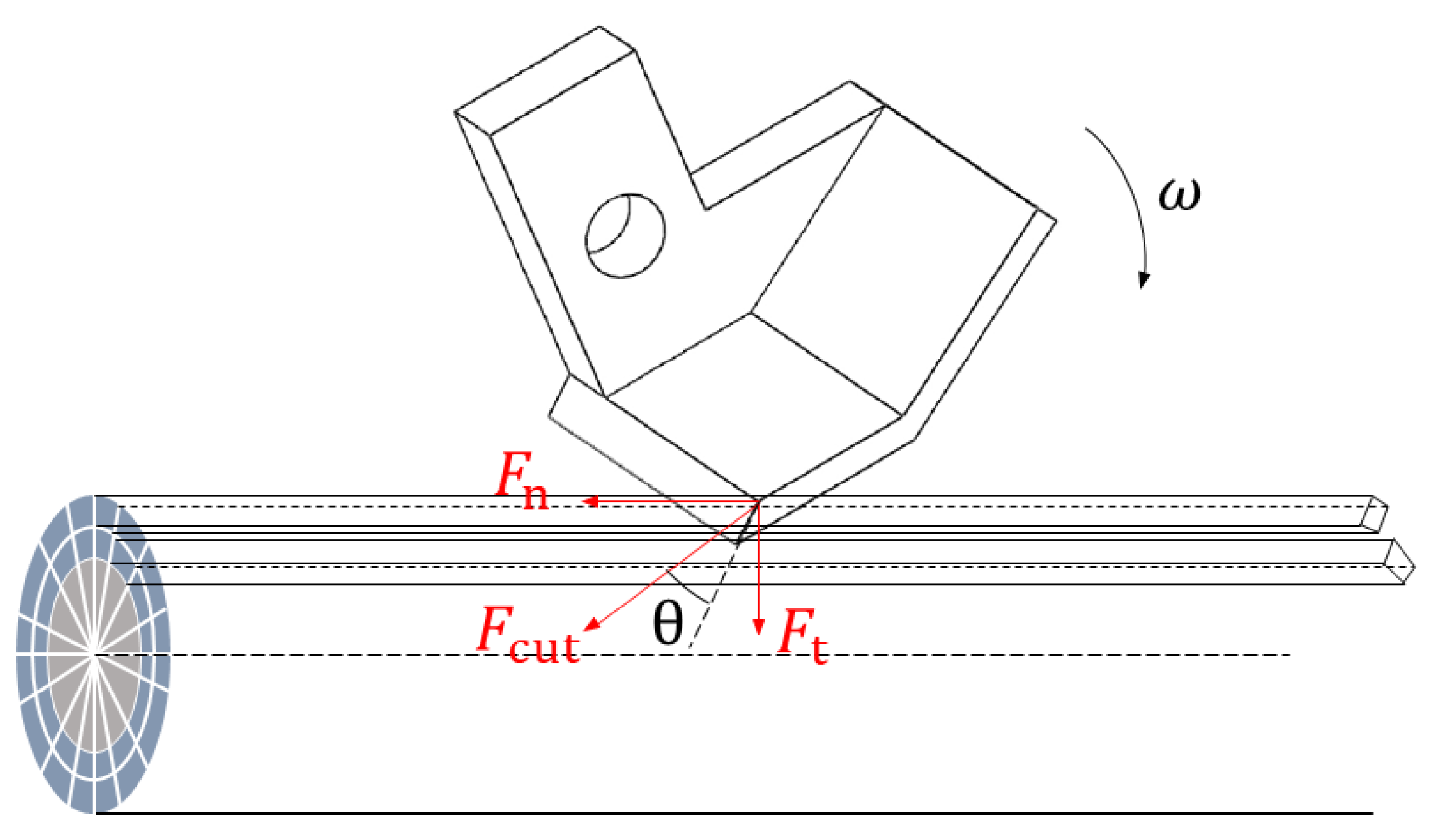
2.2.3. Performance Analysis of Antisticking Tools
2.2.4. Design and Analysis of Tool Inclination
2.3. Antitangling and Sticking Tool Simulation Test Method
2.3.1. Finite Element Analysis of Antisticking Tools
2.3.2. Discrete Metamodeling of Soil Straw
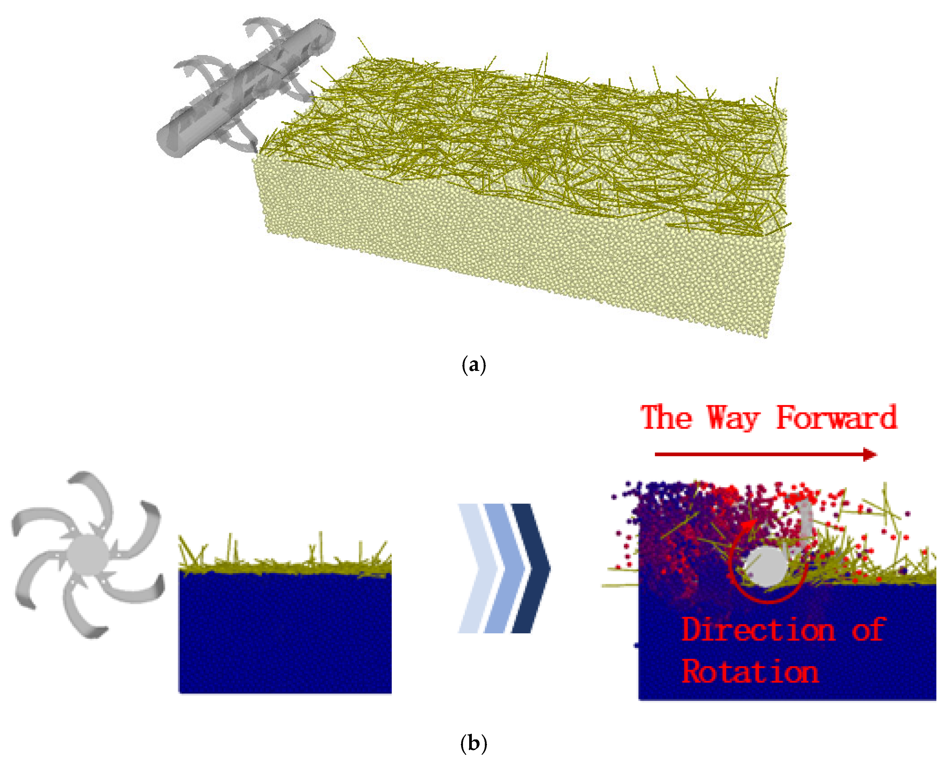
2.3.3. Simulation
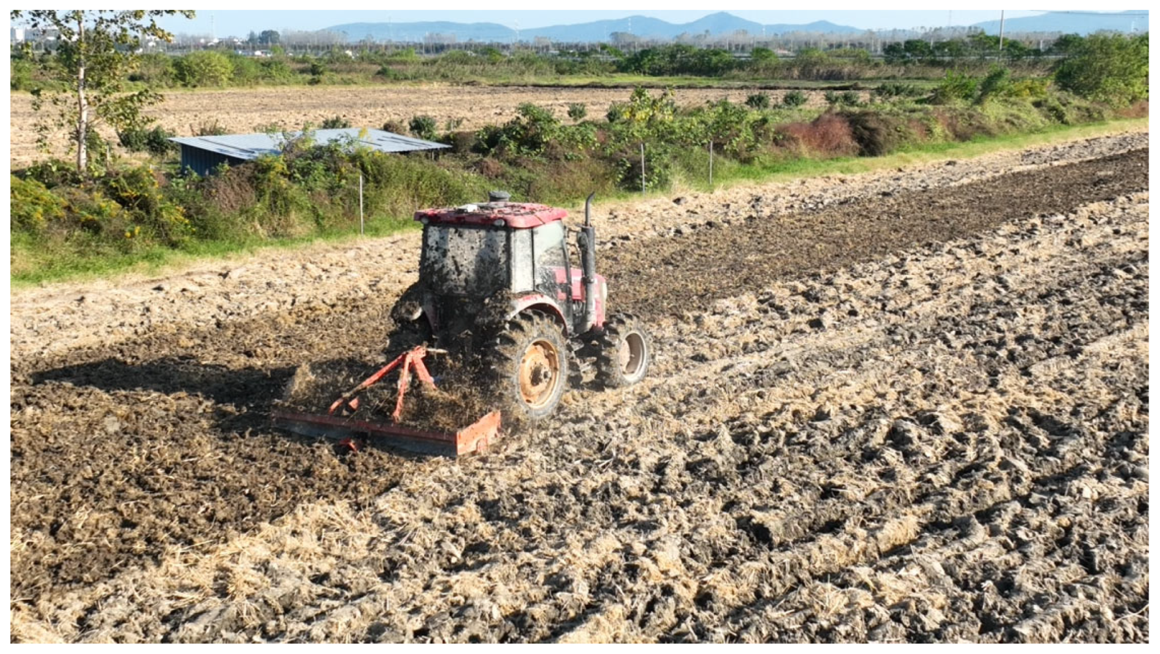
2.4. Field Trial
2.4.1. Average Torque
2.4.2. Operating Efficiency
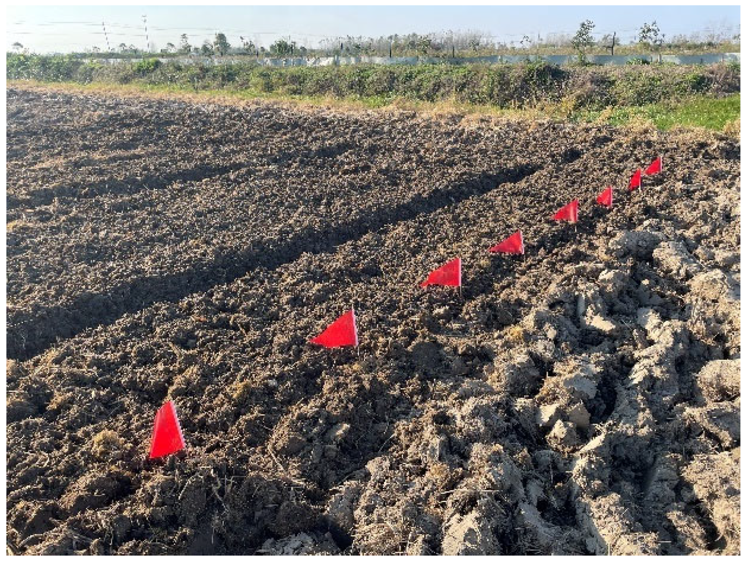
2.4.3. Operational Pass Rate
3. Results
3.1. Kinetic Analysis
3.1.1. Torque Trend
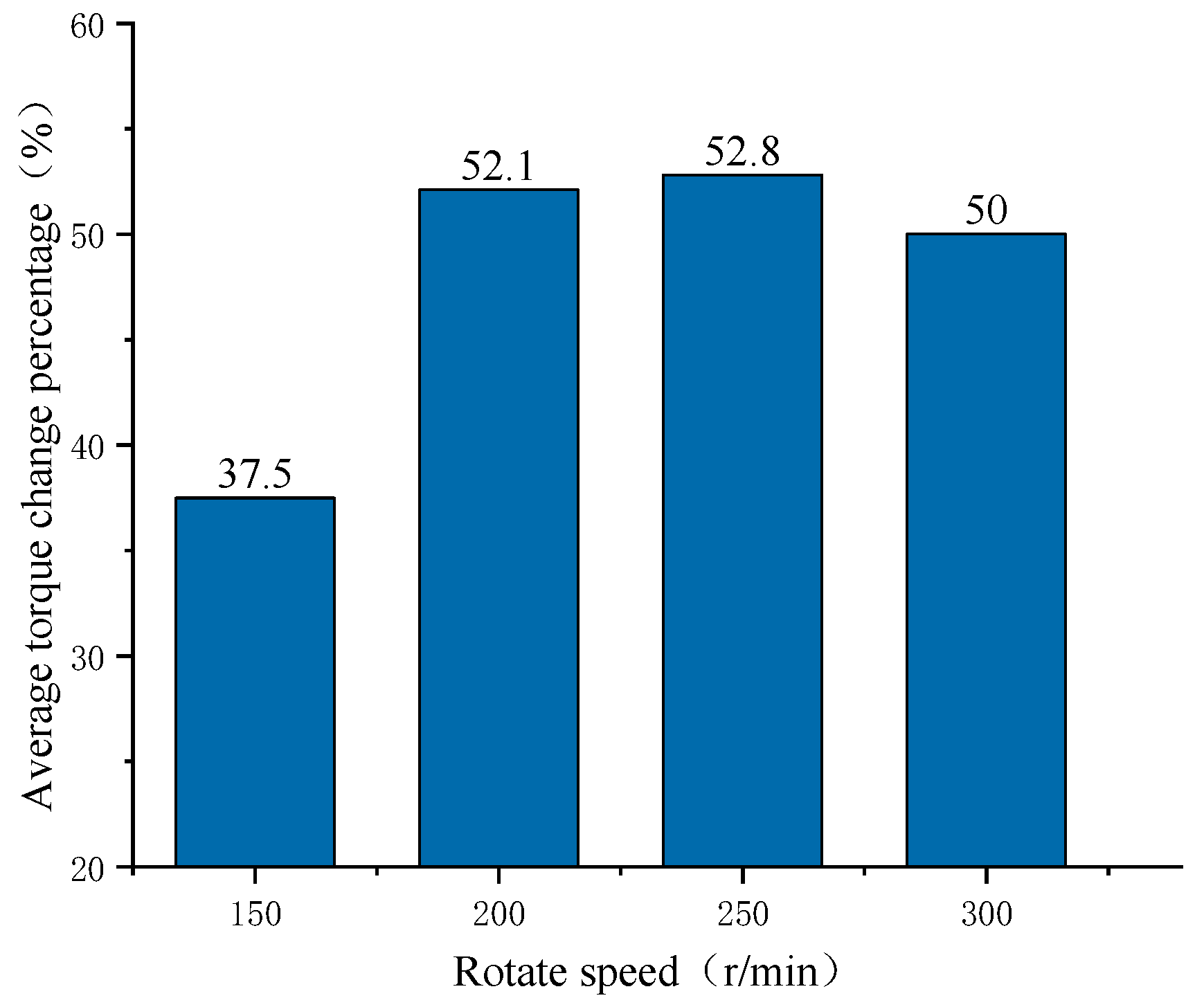
3.1.2. Average Torque Trend
3.2. Field Trial Analysis
4. Discussion
5. Conclusions
- (1)
- An antistalking tool was designed, and the working principle of the tool was elaborated. Through motion force analysis, the blade inclination of the antistalking tool, which has strong crushing ability and soil planing ability, was designed. Compared to other related studies, this tool is more effective for the antitwisting of knife rolls in wet clay soils.
- (2)
- The finite element analysis of the antisticking tool verified that the tool can meet the actual working requirements and the design of the antisticking tool effectively solved the problems of soil adhesion and straw entanglement.
- (3)
- Using the discrete element simulation technique, combined with the establishment of the tool–soil–straw mutual contact model, a simulation study was carried out to investigate the operation process of the tool with or without antisticking properties at a forward speed of 0.5 m/s and a plowing depth of 100 mm. The torque of the tool with and without antistalking tool was analyzed under four different working conditions, i.e., the rotational speed of the knife shaft was 150, 200, 250, and 300 r/min, and the results showed that the average torque with the antistalking tool was smaller than that of the tool without antistalking tool, with obvious decreases of 37.1%, 52.1%, 52.8%, and 50.0%, respectively.
- (4)
- The field test showed that the knife roller basically did not undergo entanglement; for the tool to meet the rotary tillage operation needs of the rice field with sticky and wet soil, the average operating rate was 0.57 hm2/h and the operation of the pass rate was 95.72%.
- (5)
- Field tests were conducted under the same working conditions, and the basic laws of torque changes of two kinds of rotary tillage knives under four working conditions were obtained. The average torque of the simulation and test of the two kinds of rotary tillage knives under four knife shaft speeds were analyzed, and the correlation coefficients of the average torque change curves with and without antisticking knives were obtained, i.e., 0.994 and 0.973, respectively. These results verified the accuracy of the simulation model and the consistency between the simulation and the field test.
Author Contributions
Funding
Data Availability Statement
Acknowledgments
Conflicts of Interest
References
- Zhang, Z.; Sun, D.; Li, T.C. Effects of Water-Saving Irrigation and Reducing Phosphorus Fertilizer on Rice Yield, Phosphorus Utilization and Soil Phosphorus Balance in Black Soil. Trans. Chin. Soc. Agric. Eng. 2022, 38, 67–74. [Google Scholar]
- Wu, T.; Cai, W.; Song, X.; Tan, Y. Research on the Influence of Cutter Roll Optimization of Rotary Tiller on Its Operation Performance. J. Phys. Conf. Ser. 2023, 2419, 012016. [Google Scholar] [CrossRef]
- Sun, N.N.; Wang, X.Y. Design and Experiment of Differential Sawing Rice Straw Chopper for Turning to Field. Trans. Chin. Soc. Agric. Eng. 2019, 35, 267–276. [Google Scholar]
- Zhang, X.Y.; Wang, Z.Q.; Li, Y.; Liang, D. Design and Experiment of Sliding-Cutting and Anti-Twining Returningdevice for Banana Straw. Trans. Chin. Soc. Agric. Eng. 2018, 34, 26–34. [Google Scholar]
- Zhang, X.Y.; Yang, Y.M. Optimal Design and Experiment of Double Fixed Knife Slip-Cuttingand Anti-Tangle Banana Straw Crushing and Returning Machine. Trans. Chin. Soc. Agric. Mach. 2024, 55, 36–49. [Google Scholar]
- Li, Y.; Guo, C.F.; Yao, D.Y. Design and Experiment of Banana Straw Crushing and Returning Machinewith Anti-Wrapping Device Supported by Flailing Blade. Trans. Chin. Soc. Agric. Eng. 2021, 37, 11–19. [Google Scholar]
- Shi, R.J.; Dai, F.; Zhao, W.Y.; Liu, X.L. Analysis of the Anti-Winding Mechanism for the Interaction between Flaxstem and Harvest Header in Hilly Area. Trans. Chin. Soc. Agric. Eng. 2025, 41, 11–19. [Google Scholar]
- Du, J.; Heng, Y.; Zheng, K.; Luo, C.; Zhu, Y.; Zhang, J.; Xia, J. Investigation of the Burial and Mixing Performance of a Rotary Tiller Using Discrete Element Method. Soil Tillage Res. 2022, 220, 105349. [Google Scholar] [CrossRef]
- Li, X.; Du, Y.; Liu, L.; Mao, E.; Wu, J.; Zhang, Y.; Guo, D.A. Rapid Prototyping Method for Crop Models Using the Discrete Element Method. Comput. Electron. Agric. 2022, 203, 107451. [Google Scholar] [CrossRef]
- Yan, D.; Yu, J.; Wang, Y.; Zhou, L.; Sun, K.; Tian, Y. A Review of the Application of Discrete Element Method in Agricultural Engineering: A Case Study of Soybean. Processes 2022, 10, 1305. [Google Scholar] [CrossRef]
- Li, B.; Chen, Y.; Chen, J. Modeling of Soil–Claw Interaction Using the Discrete Element Method (DEM). Soil Tillage Res. 2016, 158, 177–185. [Google Scholar] [CrossRef]
- Shi, Y.; Xin, S.; Wang, X.; Hu, Z.; Newman, D.; Ding, W. Numerical Simulation and Field Tests of Minimum-Tillage Planter with Straw Smashing and Strip Laying Based on EDEM Software. Comput. Electron. Agric. 2019, 166, 105021. [Google Scholar] [CrossRef]
- Fang, H.M.; Ji, C.Y. Simulation Analysis of Straw Movement in Straw-Soil-Rotary Blade System. Trans. Chin. Soc. Agric. Mach. 2016, 47, 60–67. [Google Scholar]
- Wang, Z.; Li, X.; Li, J.; Qiu, Y.; Gu, T.; Wang, H. Analysis of the Interaction Mechanism between Straw Soil Rotary Tillage Blade during Rotary Tillage Process. Sci. Rep. 2025, 15, 691. [Google Scholar] [CrossRef]
- Zhang, S.; Huang, Y.; Gao, X.; Bi, Y.; Dong, J.; Zhao, H.; Zhao, P.; Jia, X. Evaluating the Influence of Straight-Plain Types of Rotary Tiller Blades with Various Edge Curves on Maize Residue Using DEM. Biosyst. Eng. 2025, 250, 49–61. [Google Scholar] [CrossRef]
- Zhu, D.; Shi, M.; Yu, C.; Yu, Z.; Kuang, F.; Xiong, W.; Xue, K. Tool-Straw-Paddy Soil Coupling Model of Mechanical Rotary-Tillage Process Based on DEM-FEM. Comput. Electron. Agric. 2023, 215, 108410. [Google Scholar] [CrossRef]
- Zhang, J.; Xia, M.; Chen, W.; Yuan, D.; Wu, C.; Zhu, J. Simulation Analysis and Experiments for Blade-Soil-Straw Interaction under Deep Ploughing Based on the Discrete Element Method. Agriculture 2023, 13, 136. [Google Scholar] [CrossRef]
- Horner, D.A.; Peters, J.F.; Carrillo, A. Large Scale Discrete Element Modeling of Vehicle-Soil Interaction. J. Eng. Mech. 2001, 127, 1027–1032. [Google Scholar] [CrossRef]
- Milkevych, V.; Munkholm, L.J.; Chen, Y.; Nyord, T. Modelling Approach for Soil Displacement in Tillage Using Discrete Element Method. Soil Tillage Res. 2018, 183, 60–71. [Google Scholar] [CrossRef]
- Zhou, H.; Chen, Y.; Sadek, M.A. Modelling of Soil–Seed Contact Using the Discrete Element Method (DEM). Biosyst. Eng. 2014, 121, 56–66. [Google Scholar] [CrossRef]
- GB/T 5669-2017; National Technical Committee for Standardization of Agricultural Machinery (SAC/TC 201) Rotary Tiller—Rotary Blades and Blade Holders. 2017. Available online: https://www.chinesestandard.net/PDF/English.aspx/GBT5669-2017 (accessed on 20 April 2025).
- Zheng, K.; McHugh, A.D.; Li, H.; Wang, Q.; Lu, C.; Hu, H.; Liu, W.; Zhang, Z.; Liu, P.; He, J. Design and Experiment of Anti-Vibrating and Anti-Wrapping Rotary Components for Subsoiler Cum Rotary Tiller. Int. J. Agric. Biol. Eng. 2019, 12, 47–55. [Google Scholar] [CrossRef]
- Xie, C.; Wei, W.; Zhu, Y.; Xiao, M.; Chen, T. Wear Reduction Damage Mitigation and Operational Reliability Analysis of Rotary Tiller Knives Based on the Self-Excited Vibration Theory. Comput. Electron. Agric. 2025, 231, 109991. [Google Scholar] [CrossRef]
- Karoonboonyanan, S.; Salokhe, V.M.; Niranatlumpong, P. Wear Resistance of Thermally Sprayed Rotary Tiller Blades. Wear 2007, 263, 604–608. [Google Scholar] [CrossRef]
- Qiu, Z.; Wang, Y.; Tang, Y.; Luo, W.; Ye, Z. Analysis of Blockage and Wrapping by Leaves in the Cutting Mechanism of a Sugarcane Leaf Shredder. Biosyst. Eng. 2021, 211, 152–166. [Google Scholar] [CrossRef]
- Shi, J.; Shan, Z.; Yang, H. Research on the Macro- and Meso-Mechanical Properties of Frozen Sand Mold Based on Hertz-Mindlin with Bonding Model. Particuology 2024, 88, 176–191. [Google Scholar] [CrossRef]
- Xiao, M.; Niu, Y.; Wang, K. Design of Self-Excited Vibrating Rotary Tiller and Analysis of Its Performance in Reducing Torsion and Consumption. Trans. Chin. Soc. Agric. Mach. 2022, 53, 52–63. [Google Scholar]
- Xia, J.; Zhang, P. Calibration and Verification of Flexible Rice Straw Model by Discrete Element Method. Trans. Chin. Soc. Agric. Mach. 2024, 55, 174–184. [Google Scholar]
- Li, Z.; Li, Y. Design and Experiment of the Banana Stalk Crushing and Returning Machine with Lengthways Double Rollers Type. J. Chin. Agric. Mech. 2020, 41, 180–184. [Google Scholar] [CrossRef]
- Zhu, A.; Xu, C.; Liu, Y.; Wang, J.; Tan, X. Design and Experiment of Oblique Stubble-Cutting Side-Throwing Anti-Blocking Device for No-Tillage Seeder. Agriculture 2024, 14, 2250. [Google Scholar] [CrossRef]


| Technical Parameters | Value |
|---|---|
| Overall dimensions (mm × mm × mm) | 2100 × 880 × 400 |
| Power (kW) | 100 |
| Gross mass (kg) | 600 |
| Travel speed (m/s) | 0.5–1.85 |
| Tilling depth (mm) | 100–350 |
| Properties | Density/(kg/m3) | Poisson’s Ratio | Modulus of Elasticity/Pa |
|---|---|---|---|
| Value | 7860 | 0.3 | 2.1 × 10¹¹ |
| Technical Parameters | Value |
|---|---|
| 65 Mn steel density/(kg/m3) | 7850 |
| 65 Mn steel shear modulus/Pa | 7.9 × 10¹⁰ |
| 65 Mn steel Poisson’s ratio | 0.3 |
| Soil density/(kg/m3) | 1850 |
| Soil Poisson’s ratio | 0.25 |
| Soil shear modulus/Pa | 1 × 10⁶ |
| Soil–soil static friction factor | 0.5 |
| Soil–soil rolling friction factor | 0.5 |
| Soil–soil recovery coefficient | 0.6 |
| Soil–65 Mn static friction factor | 0.6 |
| Soil–65 Mn rolling friction factor | 0.05 |
| Soil–65Mn recovery coefficient | 0.6 |
| Soil bond radius/mm | 8.0 |
| Soil normal bond stiffness/(N/m3) | 5 × 10⁷ |
| Soil tangential bond stiffness/(N/m3) | 9 × 10⁷ |
| Soil normal bond critical stress/Pa | 5 × 10⁵ |
| Soil tangential bond critical stress/Pa | 5 × 10⁵ |
| Technical Parameters | Value |
|---|---|
| Poisson’s ratio of rice straw μ | 0.4 |
| Density of rice straw/(kg/m3) | 241 |
| Shear modulus of rice straw Pa | 1 × 10⁶ |
| Straw–straw collision recovery coefficient | 0.1–0.5 |
| Straw–65Mn steel collision recovery coefficient | 0.1–0.5 |
| Rotary Cutter Type | Cutter Shaft Speed/(r∙min−1) | Average Torque/(N∙m) |
|---|---|---|
| No antitangle knives | 150 | 81.4 |
| 200 | 108.4 | |
| 250 | 124.9 | |
| 300 | 138.7 | |
| Antitangle knives | 150 | 51.2 |
| 200 | 51.9 | |
| 250 | 58.9 | |
| 300 | 69.3 |
| Rotary Cutter Type | Average Torque of Single Test | Average Torque | ||
|---|---|---|---|---|
| Antitangle Knives | No Antitangle Knives | Antitangle Knives | No Antitangle Knives | |
| 150 | 53.4 | 112.7 | 57.4 | 113.4 |
| 59.2 | 113.1 | |||
| 59.6 | 114.4 | |||
| 60.3 | 138.2 | |||
| 200 | 55.2 | 142.1 | 59.7 | 138.4 |
| 63.6 | 134.9 | |||
| 71.7 | 143.6 | |||
| 69.4 | 144.9 | |||
| 250 | 70.7 | 144.4 | 70.6 | 138.4 |
| 79.7 | 157.2 | |||
| 78.3 | 155.4 | |||
| 80.2 | 154.2 | |||
| 300 | 150 | 51.2 | 79.4 | 155.6 |
| 200 | 51.9 | |||
| 250 | 58.9 | |||
| 300 | 69.3 | |||
Disclaimer/Publisher’s Note: The statements, opinions and data contained in all publications are solely those of the individual author(s) and contributor(s) and not of MDPI and/or the editor(s). MDPI and/or the editor(s) disclaim responsibility for any injury to people or property resulting from any ideas, methods, instructions or products referred to in the content. |
© 2025 by the authors. Licensee MDPI, Basel, Switzerland. This article is an open access article distributed under the terms and conditions of the Creative Commons Attribution (CC BY) license (https://creativecommons.org/licenses/by/4.0/).
Share and Cite
Geng, G.; Chen, T.; Xiao, M.; Xie, C.; Tang, C. The Design and Testing of a New Antitangling and Antisticking Knife for a Wet Clay Soil Environment. Agriculture 2025, 15, 1102. https://doi.org/10.3390/agriculture15101102
Geng G, Chen T, Xiao M, Xie C, Tang C. The Design and Testing of a New Antitangling and Antisticking Knife for a Wet Clay Soil Environment. Agriculture. 2025; 15(10):1102. https://doi.org/10.3390/agriculture15101102
Chicago/Turabian StyleGeng, Guosheng, Tailai Chen, Maohua Xiao, Chenshuo Xie, and Cungan Tang. 2025. "The Design and Testing of a New Antitangling and Antisticking Knife for a Wet Clay Soil Environment" Agriculture 15, no. 10: 1102. https://doi.org/10.3390/agriculture15101102
APA StyleGeng, G., Chen, T., Xiao, M., Xie, C., & Tang, C. (2025). The Design and Testing of a New Antitangling and Antisticking Knife for a Wet Clay Soil Environment. Agriculture, 15(10), 1102. https://doi.org/10.3390/agriculture15101102