Article

Design and Experiment of Oil-Electric Hybrid Air-Suction Sorghum Plot Seeder

1
College of Engineering, Heilongjiang Bayi Agricultural University, Daqing 163319, China
2
College of Information and Electrical Engineering, Heilongjiang Bayi Agricultural University, Daqing 163319, China
*
Author to whom correspondence should be addressed.
Agriculture 2024, 14(3), 432; https://doi.org/10.3390/agriculture14030432
Submission received: 14 January 2024 / Revised: 21 February 2024 / Accepted: 24 February 2024 / Published: 7 March 2024
(This article belongs to the Section Agricultural Technology)

Abstract

:
To tackle the issues of low seeding accuracy and seed injury caused by the seeders utilized at a small scale and in the plot seeding of sorghum in mountainous or hilly regions, this study presents the design of an oil–electric hybrid air suction sorghum plot seeder. The main working parts of the seeder are described, and the performance of the seed-mixing device is simulated using EDEM software. An oil–electric hybrid drive mode is used to provide power for operation and to the seed-metering device and fan. Additionally, a sowing control and monitoring system is designed using a single-chip microcomputer controller to ensure uniform plant spacing at different forward speeds. A multi-factor experiment is conducted using the central synthesis method to determine the optimal operating parameters of the seed-metering device through bench tests. The results show that a profile hole diameter of 2.5 mm on the seed tray, a negative-pressure chamber vacuum of 8.0 kPa, and a seed-metering device speed of 28 r/min result in a 95.95% pass rate, 0.5% missing rate, and 3.55% reseeding rate. The deviation between the experimental and analytical results that validate the optimum parameters is kept within acceptable limits. Field tests are conducted at different forward speeds using the optimum parameter combinations, and a comparison is made with the widely used duckbill planter. The results show pass, missing, and reseeding rates of 94.41%, 2.3%, and 3.29%, respectively. The missing monitoring error is less than 7.19%. All of the indices of the oil–electric hybrid air suction sorghum plot seeder are superior to those of the duckbill planter; thus, it fulfills the agronomic requirements for seeding a sorghum plot.

1. Introduction

Seed is the fundamental core of agriculture, and it plays a dominant role in the development of agriculture [1]. Due to the rise in the economic level, people’s dietary requirements are increasing day by day. According to previous studies, the consumption of sorghum is gradually increasing, but the efficiency of sorghum cultivation in some areas is not high, indicating that the cultivation of sorghum seeds still has some room for development [2,3,4].
A seeding plot is a fundamental aspect of seed cultivation experiments. In the 1980s, Wintersteiger Austria launched the first self-propelled plot seeder; this uses more advanced hydraulic transmission through a hydraulic motor to regulate the rotation speed and direction of the seed dispenser, and it uses solenoid control valves to alter the positive and negative pressure, clear the seed, and change the function of the seed. As it is difficult to meet technical needs when changing the seed, this model solves the researchers’ problem of clearing the seed in plot test seeding machines [5].
At present, in the field of plot seeders, Wintersteiger Austrian, Almaco USA, and Haldrup Denmark are in the leading positions in terms of technology. For example, the row motion electric strip seeder with an encoder and a servomotor allows for accurate seed and fertilizer application. Other advanced models can also use computer and satellite control to achieve high-precision path correction, indicating that current plot seeding is moving in the direction of unmanned operation [6,7,8,9,10,11,12,13].
However, due to costs and scale limitations, small mechanical seeders, such as duckbill [14] and spoon clamp seeders, are mostly used in small-scale environments in developing countries [15,16]. These seeders exhibit phenomena such as low sowing precision [17], poor flexibility [18], and seed breakage [19]. After use, the operator needs to thin out the seedlings. Tang et al. [20] designed a precision seed-metering device that uses positive- pressure airflow to reduce seed missing during corn seeding. Chen et al. [21] developed a soybean seed dispenser that uses air suction to meet the planting requirements of monoculture with three rows. Xiong et al. [22] used positive-pressure airflow and a mechanical seed expeller to remove excess seed and prevent reseeding. The use of seed dischargers that apply airflow constraints can be a viable solution to issues such as missing, reseeding, and seed injury. However, they are primarily used in large planters [23,24] and are not suitable for use in small-scale environments. Therefore, the development of a suitable pneumatic seed-metering device is the direction for plot seeders.
In mountainous or hilly areas, limited by environmental conditions and running power, it is impossible to use sowing machinery models pulled by large tractors. In recent years, most researchers have focused their attention on small self-propelled planters. For example, Wang et al. [25] designed and tested an electrically driven pneumatic carrot planter in a greenhouse by using a small walk-behind trolley machine for traction power. To a certain extent, the automation and precision of carrot planting in greenhouses have been improved. Lai et al. used a gasoline engine for traction power [26]. In order to solve the low mechanization rate of ginseng sowing, a ginseng precision seeder with ditching and a type of seeding monomer was designed. This reduced the high seed injury rate of traditional ginseng sowing. Therefore, a flexible self-propelled seeder is more suitable than a large seeder for the sowing of small plots.
A conventional planter guarantees the synchronization of forward speed and plant spacing by transmitting power from the ground wheel and gearbox. However, it is prone to reseeding and missing due to ground wheel slippage or idling. Conversely, a large-scale air suction planter utilizes a motor-driven seed discharger, which effectively addresses this issue. Ensuring consistent spacing has become a new challenge. Chen et al. developed a motor-driven precision control system for a corn no-till planter using the CANopen protocol. They utilized STM32 as the main controller and GPS to monitor the tractor speed, enabling the motor drive of the seed discharger [27]. Yu et al. designed an integrated electric-driven small peanut seeder precision seed-metering device and controller using the PID algorithm. They utilized satellite speed measurement to complete the electric drive and control modification of the seed-metering device and to achieve precision seeding control. A mathematical model was developed to describe the working process of the peanut seeder, and the motor speed was controlled effectively at different walking speeds [28]. Currently, researchers commonly use encoders, Hall sensors, radar, and GPS to detect the forward speed of a planter or tractor. They then adjust the engine speed in real time using controllers to achieve real-time synchronization between the speed of the seed dispenser and the forward speed of the planter [29].
A plot seeder for sorghum is designed in this study. It is applied to small-scale planting and a small sowing test field. The structure is simple and universal, and the sowing can be monitored. The forces and movements of the sorghum seeds in the seed-metering device are analyzed, and the main parameters of the device are determined. The performance of the seed-mixing device design is analyzed and verified through the use of EDEM software (https://altair.com/edem/, accessed on 1 February 2023) and bench tests. The central composite design test method is used to obtain the optimal parameter combinations for the bench test, and the optimal parameters are applied to the parameter configurations for the field test of the seeder. To ensure the stable operation of the seeder on farmland, fuel and electricity are used to provide power for operation and to the seed-metering device, respectively. A rotary encoder, microcontroller, and optical fiber sensor are used to adjust and monitor the seeder.

2. Materials and Methods

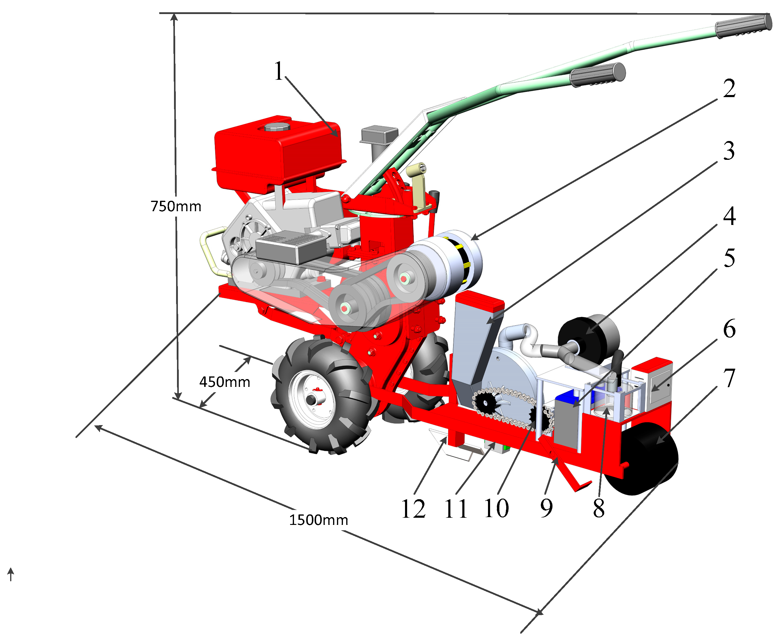
2.1. Working Principle of Plot Seeder

Figure 1 depicts the plot seeder’s structure, and the technical parameters are shown in Table 1. The oil–electric hybrid air suction sorghum plot seeder is mainly composed of a diesel engine, generator, seeder, fan, battery, electric control box, suppression wheel, seed clearing mechanism, soil coverer, motor, missing monitoring system, and trencher.
During operation, the planter is driven by a tractor. The frame is connected to the tractor, and the trench opener is mounted underneath. The seed-metering device is run by a motor and a fan, which are supplied with energy from a battery. The tractor drives the generator to ensure a stable current. The tractor’s speed and motor operation are detected by a screw encoder to form a fixed ratio, which is then controlled by the single-chip microcomputer to ensure consistent spacing between two seeds during each drop. Once the seeds are dropped, they are covered with soil using a covering device and compacted by the suppression wheel. The mechanism for clearing seeds is equipped to facilitate the suction and storage of unfinished seeds in the seed discharger, ensuring the complete clearing of seeds in the seed box and avoiding the mixing of different varieties of seeds.

2.2. Design of Key Components of Plot Seeder

2.2.1. Force Analysis of Sorghum Seed

The seed-metering device used in conjunction with the oil–electric hybrid air suction sorghum plot seeder consists of several components, including a seed scraper, left and right shells, a seed shaft, a seed tray, and a seed-mixing wheel. The seed box is linked to the right shell, and the fan is connected to the left shell, forming a horseshoe-shaped air chamber under negative pressure. Please refer to Figure 2a for a schematic of the overall structure. To enhance the ease of examining the seed-metering device during fieldwork, the left housing has undergone processing of the seal ring and pressure plate.
During operation, the fan creates positive- and negative-pressure zones, dividing the seed tray into three areas: seed-filling, seed-carrying, and seed-dropping areas. Seeds drop from the seed box through the drop guidance area to the seed-filling area. The seed tray revolves as a result of the seed shaft’s drive. Seeds are sucked into the profiling holes of the seed tray under negative pressure. Once transferred to the seed-scraping area, excess seeds are hung on the profiling holes by the seed scraper to ensure that each hole only contains one seed. When the seeds are transferred to the seed drop area, the negative pressure dissipates, the seeds fall under their own gravity, and this completes the seeding process. The functioning of the seed-metering device is illustrated in Figure 2b.
The initial study comprises an examination of the physical properties of sorghum seeds. The results of the measurements and calculations are presented in Table 2.
The table shows that sorghum seeds exhibit high sphericity and an effective cross-section that is almost circular. To enhance the adsorption potency of the profiling pore within identical negative-pressure parameters, the profiling hole parameters comprise an upper plane diameter d1, a lower plane diameter d2, and depth s.
The efficiency of the seeding is paramount to the operational functionality of the seed-metering device, and the seeds in the adsorption state are analyzed by force. As illustrated in Figure 3, the seeds are consecutively subjected to their own gravitational force G, negative-pressure adsorption force F, centrifugal force J, the supporting forces N2 and N1 of the upper and lower contact surfaces the profiling hole, friction Fr from the lower contact surface, and the internal friction Ff of seeds during movement with the counterclockwise rotation of the seed tray. In this case, the moment equation in the YZ plane is as follows:
F d 1 2 = Q h ,
where Q represents the net force of vectors G, J, and Ff in the Y direction, and h denotes the distance from the center of the seed to the upper end of the seed tray.
When a seed exits the seed-carrying area and enters the seed-dropping area, the negative pressure and suction force F cease to exist. At this time, the seed and the seed tray are in pseudo-contact, and in the critical state of falling, the contact surface support force N2 on the profiling hole disappears. The balance equation is then established in both the Y and Z directions:
F r · l 2 = Q · h N 1 · s i n σ = F r · c o s σ h l 2 s s i n σ = 2 h l ,
where σ represents the angle between the seed contact and the Y-axis. Upon solving the equation above, the resulting equation is
s = l 2 1 1 N 1 Q 2 ,
According to the relationship in Equation (3), the depth of the profiling hole must be less than half of a certain size of sorghum. Based on the size of sorghum, its average triaxial size is 3.45 mm. Therefore, we selected the depth of the profiling hole as s = 1.6 mm and the lower plane diameter d2 as half of the triaxial size of sorghum seeds, which is d2 = 0.5 mm, the smallest average size. As per the manual for designing agricultural machinery, the profile hole of the seed tray must have a plane diameter that is 0.6~0.7 times the average triaxial size of the seed. This study found that sorghum seeds have an average triaxial size range of W = 2.39~4.30 mm, and the upper plane diameter of the profile hole in the seed tray is approximately d1 = 1.2~3.8 mm.

2.2.2. Kinematic Analysis of Seed

The diameter of the seed tray and the number of profile holes directly affect both the sowing speed and plant spacing. A higher number of profile holes results in a slower seed discharge, a longer time for the profiling holes to remain in the filling chamber, and more effective filling. By analyzing the staying time of “t” in the seeding chamber, Equation (4) is obtained:
t = π α 180 ω ϖ ω = π n 30 v L = Z n 60 ,
where α represents the angle of the center of the circle occupied by the seeding area in degrees, °; ω is the angular velocity of the seed tray, rad/min; n denotes the speed of the seed-metering device, r/min; v describes the forward speed of the plot seeder, m/s; L’ indicates the plant spacing, cm; and Z stands for the quantity of holes.
After solving Equation (4), the relationship with the profiling hole’s quantity Z is obtained, as shown in Equation (5):
Z = 360 v t α   L   ,
During seeding operations, the seeder maintains a stable filling chamber angle (α), a stable running speed (v), and stable plant spacing (L’). It is important to note that the time spent by the profiling holes in the seed-filling area is directly affected by the number of profiling holes in the seed tray. Increasing the number of profiling holes can improve the pass rate of the seed-metering device. The seeder typically operates at a speed of 3.8 to 5.4 km/h. On small-scale farmland, the ridge length typically ranges from 10 to 50 meters, while plant spacing varies from 10 to 15 centimeters. According to the agricultural machinery design manual, the diameter of the seed tray (dp) should be between 140 and 260 mm. After considering all relevant factors and the overall structure of the seed-metering device, we selected a diameter of dp = 240 mm and Z = 24 profiling holes for the seed tray. To optimize seed absorption and reduce device size and complexity, we set the profiling hole depth to s =1.6 mm and the seed tray thickness to 2 mm. The seed tray is made of white steel with a low friction coefficient to minimize damage to the seeds.

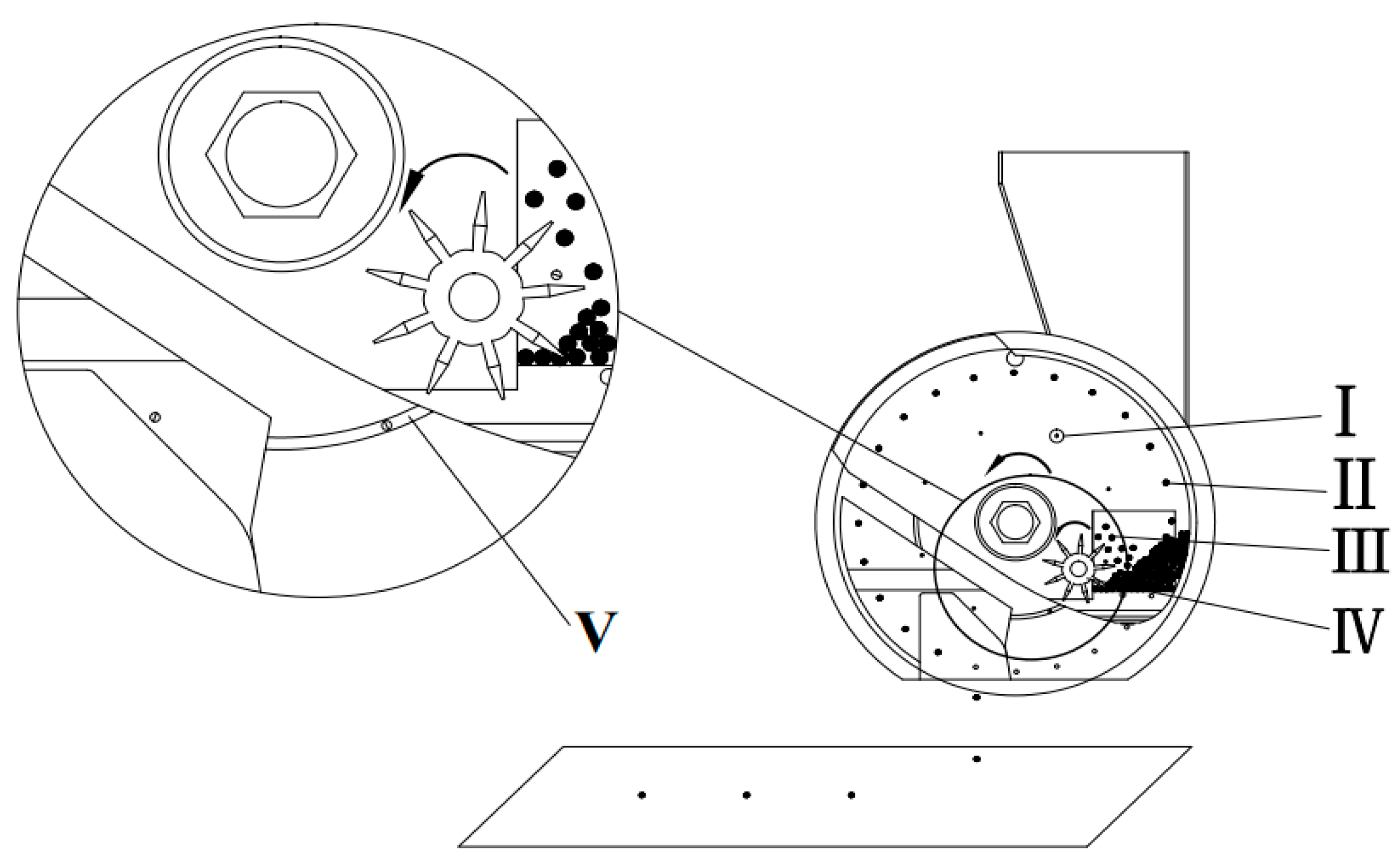
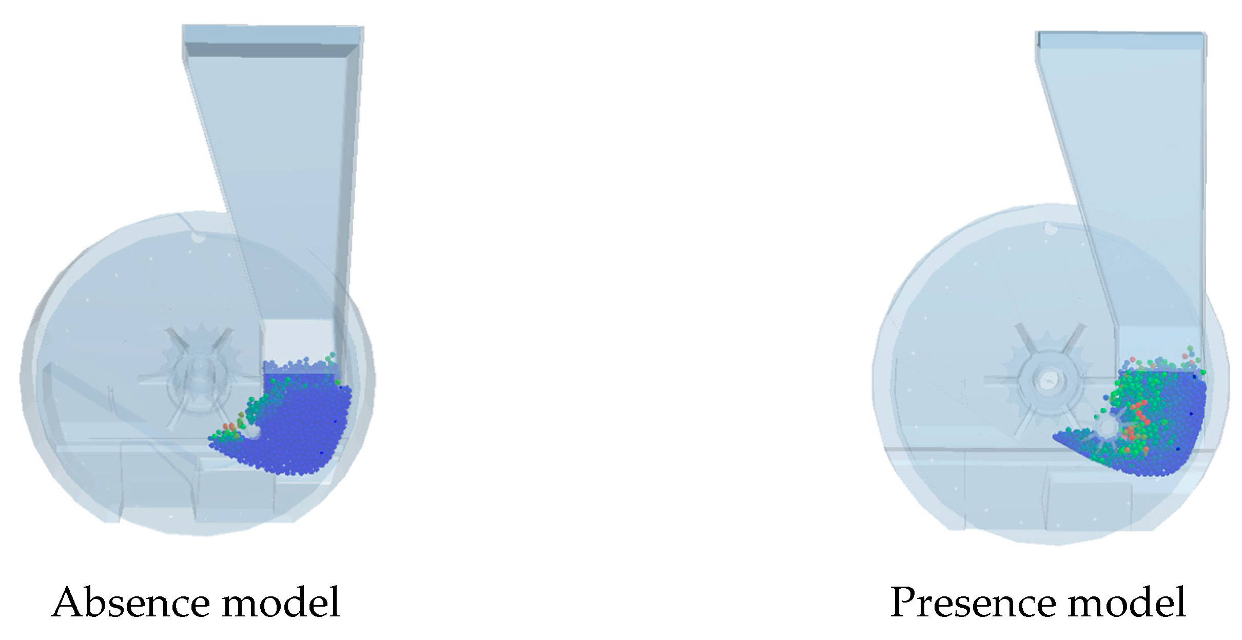
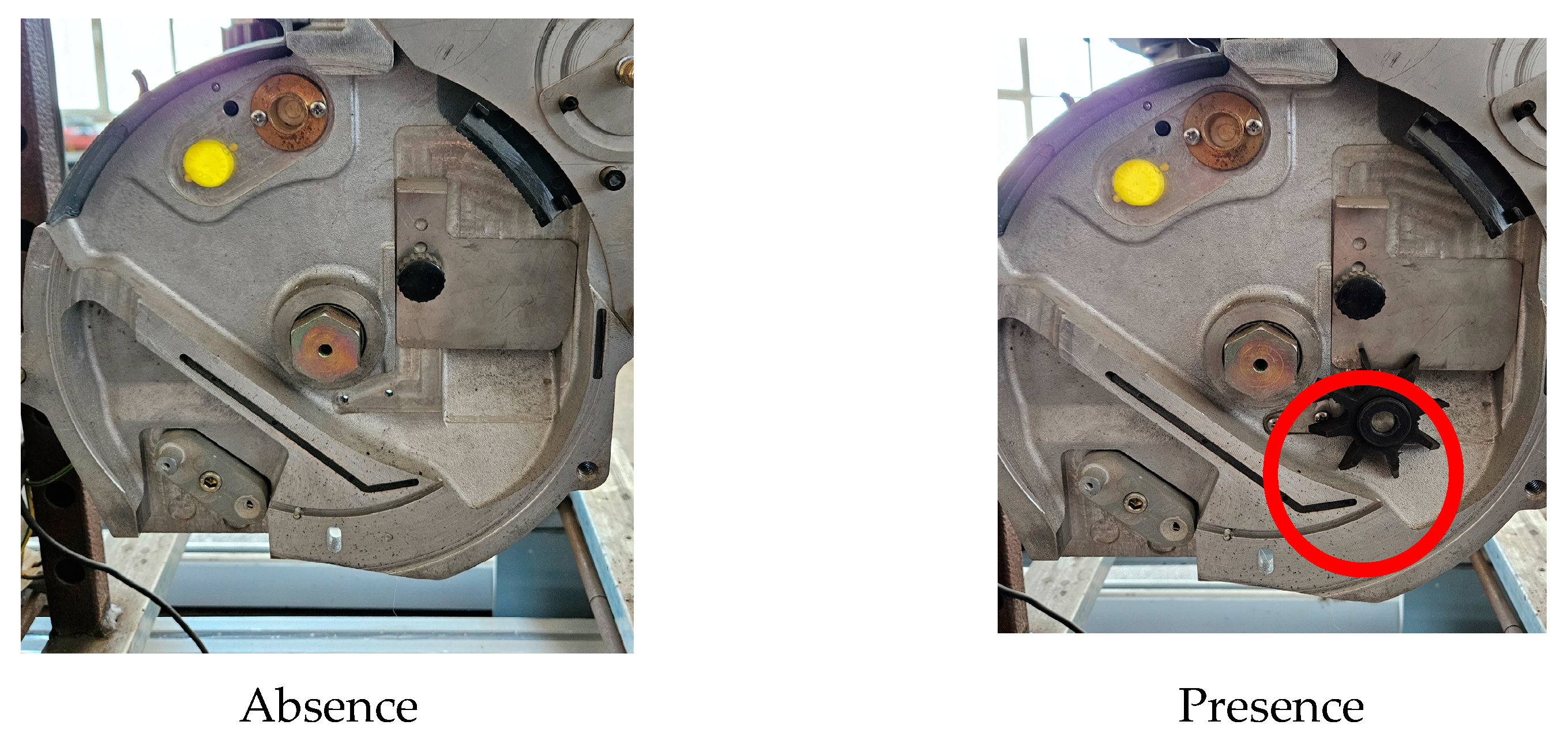
2.2.3. Design of the Seed-Stirring Device

After the seeds fall from the seed box into the seed-metering device, they can cause congestion in the seed-filling area, which can negatively impact the filling effect.
In response to this problem, a seed-stirring device is added to the design, and it essentially consists of two parts, namely, a seed guide wheel and a seed-mixing pin installed on the seed tray; the principle is shown in Figure 4. The seed-mixing pin rotates with the seed tray, scraping the seed guide wheel blades to rotate the seed guide wheel so that the seeds in the filling area are in a "disturbed" state. During the rotation of the seed tray, a groove must be present on the shell to accommodate the seed-stirring pin. This groove must be connected to the seed-filling area to prevent the seeds from entering and obstructing the tray’s rotation. The dimensions of the groove need be meticulously designed and calculated. According to the manual for designing agricultural machinery, the size of the seed-stirring pin should be 0.5~0.8 times the average three-axis size. The reference sorghum’s minimum average three-axis size was 2.39 mm. The diameter of the seed-stirring pin was calculated to be between 1.7 and 1.9 mm. The seed-stirring pin and the groove had an interference fit; therefore, the dimensions of the seed-stirring pin were determined to be 1.7 mm and the dimensions of the groove were determined to be 1.9 mm.

2.2.4. Determination of Vacuum Degree

The degree of vacuum created in the vacuum chamber must be greater than the vacuum required to adsorb a single seed. The calculation formula for determining the vacuum required for the vacuum chamber Hcmax is as follows [30,31]:
H c m a x = 80 K 1 K 2 m g h π d 1 3 1 + v 2 g r + λ ,
where M is the mass of a single seed, g; h is the distance between the center of the seed and the seed tray, mm; v’ is the linear velocity at the center of the profiling hole of the seed tray, mm; r is the radius of rotation at the profiling hole of the seed tray, m; g is the acceleration of gravity; λ is the comprehensive coefficient of the frictional resistance of the seed; K1 is the reliability coefficient of seed absorption, with the values from 1.8 to 2.0; and K2 is the external condition coefficient, with the values ranging from 1.6 to 2.0.
Based on the material properties of sorghum seeds, the given parameters are as follows [30,31]: g = 9.8 m/s2, λ = 6, K1 = 1.9, and K2 = 1.8. After applying these values to Equation (6), the calculated result is Hcmax = −2~−10 kPa. The optimal vacuum level still needs to be determined in subsequent testing.

2.2.5. Selection of Fans

At present, air suction seeders are equipped with a centrifugal fan. Because this type of fan is too large, it is not suitable for our study; thus, combined with the calculation results of the vacuum degree of the negative-pressure chamber, an electric fan was selected to provide negative-pressure to the oil–electric hybrid air suction sorghum plot seeder. A special fan produced by Heilongjiang Shuangfu Machinery Factory was chosen for the air suction seeder, of which the calibration power is 400 W, the maximum negative-pressure can reach -12 kPa, the working voltage is 12 V, and the air volume of the fan can be regulated by PMW regulation.

2.2.6. Selection of Motor

The selection of the DC servo motor used to drive the seed-metering device is crucial for the proper functioning of the seeder. The motor needs to have adequate torque, which can be calculated using a specific formula:
T 1 = K 1 T 2 μ 1 μ 2 ,
where, T1 is the motor drive torque, N·m; T2 is the maximum load of the seeder during operation, N·m; K1 is the safety factor; μ1 is the circumferential ratio; μ2 is the gear ratio of the reducer.
According to the measurement of the rotary encoder, the maximum load of the seed stirring device T2 = 4.6 N·m, combined with the actual quality and force, the safety factor K1 = 2, the circumferential transmission ratio μ1 = 1, the reducer transmission ratio μ2 = 46 was determined, and the motor driving torque T1 = 0.2 N·m was calculated. Combined with the calculation results, the working voltage DC24 V, rated power 100 W, rated torque 0.45 N·m, 485 communication, 42AIM30H servo motor produced by (Times Chaoqun Ltd. Beijing, China).

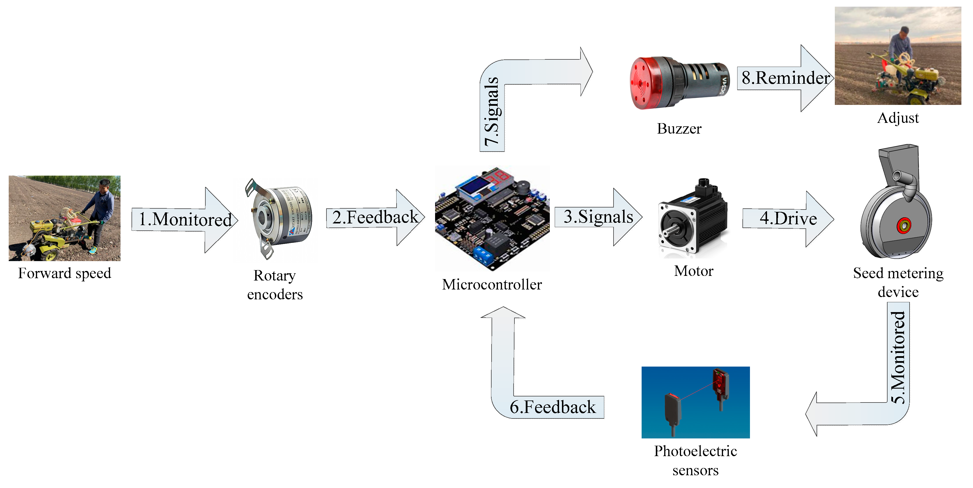
2.2.7. Seeding Control and Monitoring Systems

To ensure the rigor of the sowing work, the plant spacing should be consistent at different speeds, the forward speed of the seeder and the speed of the seed-metering device should match, and the alarm and treatment should be timely when there is an omission; thus, the sowing control and monitoring system is studied. Before sowing, the particle spacing is entered into the microcomputer as a threshold according to the grade, and the level of the current threshold is displayed on the screen. When there is an omission, the buzzer sends an alarm to remind the operator to make an adjust. A workflow diagram of the seeding control and monitoring system is displayed in Figure 5.

2.2.8. Design of Engine Power

To determine the engine power, the load of the whole plot seeder needs to be calculated and converted into the power driven by the engine. The load mainly includes two parts, the running part and the generator. The running part mainly comes from the rolling friction between the land wheel, the ditch opener, the soil coverer, and the land, which is calculated as follows:
F F = m s g f 1 + F 2 + F 3 ,
where ms is the mass of the seeder, kg; f1 is the rolling coefficient of friction F2 is the ditch opener resistance, N; and F3 is the soil coverer resistance, N.
According to [30,31], the friction coefficient of soil and steel is f1 = 0.5, and the resistance of trencher and coverer is F2 = 300 N and F3 = 45 N, respectively. By inserting the above parameters into Equation (8), the resistance of the whole machine is determined to be FF = 845 N, and the load power of the running section can be calculated as follows:
P 1 = F F v ,
The forward speed of the user is referred to as the walking speed, which ranges from 1.0 to 1.5 meters per second. The maximum power of the running part is P1 = 1267.5 W. To stabilize the current of the battery, the engine is used to drive a generator. Based on the calculation of the motor power and fan power of the seed-metering device, a generator with P2 = 1200 W is selected. Therefore, the driving power of the entire seeder is 2467.5 W. Based on the transmission loss and other factors, a 6-horsepower diesel engine with a rated power of 4.38 kW and a rated speed of 3600 r/min, along with a chain gearbox featuring a 30-speed ratio, can meet the required operating speed range of 3.6~5.4 km/h for the seeder.

2.3. Bench Test

Based on the presented force and motion analyses, it is evident that the speed of the seed-metering device, the diameter of the profile holes, and the vacuum degree of the negative-pressure chamber all have a significant influence on the seeder’s working performance. To examine the performance of the seed-metering device under these three influences, we excluded interference from other factors. The central composite design method was employed in this research to carry out multifactorial experiments. The test results were then analyzed using analysis software to determine the best combination of parameters for each factor and the best test indices, which were then set as the bench test parameters, and the test indices obtained were compared with the analysis results to ensure the accuracy of the bench test. Table 3 presents the factor-level encoding table, and each set of trials was repeated thrice, with the mean value serving as the ultimate test outcome.
A bench test was conducted in the sowing laboratory of Heilongjiang Bayi Agricultural University to evaluate the efficacy of the seed-metering device. The test material selected was Suiza No. 7 sorghum seeds, and a JPS−12 computer vision-based seed-meter performance test bench (Bona Science and Technology Ltd. Harbin, China) was used for the test. The test bench consists of several components, including a main control console, fixed bracket, height adjustment device, wind system, oil circuit system, conveyor belt, seed box, and monitoring device. Please refer to Figure 6 to see the structure of the test bench.
Following the test requirements in GB/T 6973−2005 “Testing Methods of Single Seed Drills (Precision Drills)” and taking the pass rate Y1, missing rate Y2, and reseeding rate Y3 as the test metrics, when the spacing between two seeds was 0.5~1.5 times the desired plant spacing, it was regarded as a pass; when the spacing between two seeds was less than 0.5 times the desired plant spacing, it was regarded as requiring reseeding; and when the spacing between two seeds was greater than 1.5 times the desired plant spacing, it was regarded as a miss. The sowing of 250 holes was recorded continuously for calculation.
During the testing process, the seed-metering device is mounted onto the fixed bracket and powered by the motor through the chain. The test parameters can be adjusted by turning the inverter knob on the control panel. The wind system provides positive and negative pressures to the seed-metering device being tested. The oil system pumps oil while the belt rotates. The oil brush then creates a uniform surface to ensure that the seeds falling from the seed-metering device land on the oil surface, preventing interference with the test results. The seeds that fall from the seed-metering device onto the belt are monitored by a device that includes a high-speed camera and photoelectric sensors. This device can detect any instance of missing or reseeding by the seed-metering device and transmit the parameters to the computer used as the main console in real time. The indices being examined under the test conditions can be observed on the operation interface through the supporting application MASTER.

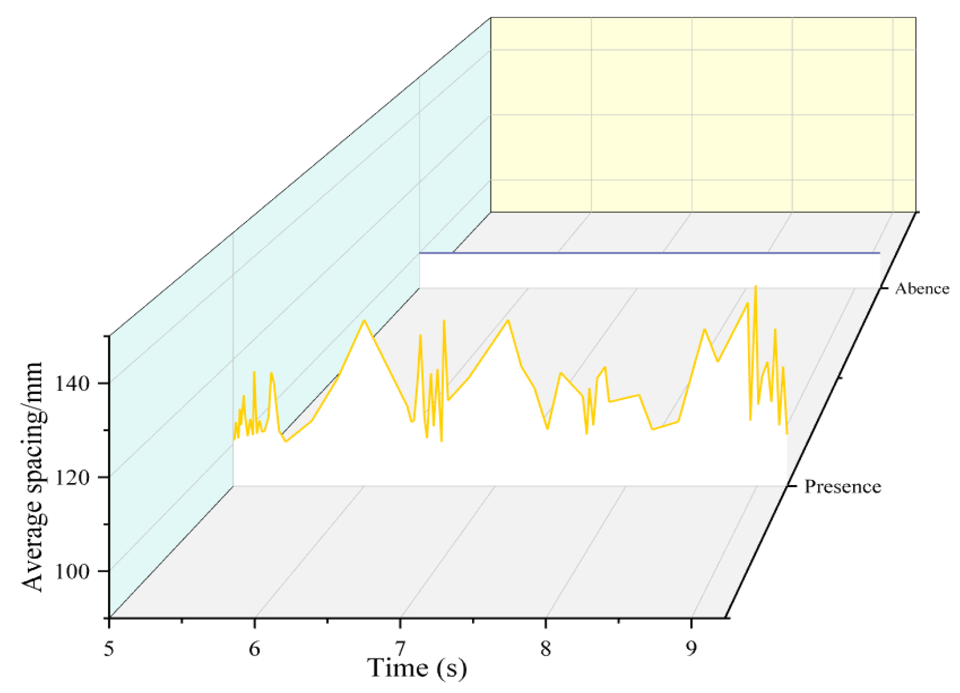
2.4. Seed-Stirring Device Tests

This study investigated the perturbation effects of the seed guide wheel and seed-mixing pin on sorghum seed through discrete element simulations and bench tests. The simulation model used a conventional spherical eccentric circle to represent the sorghum seed, as shown in Figure 7. The appropriate shell, seed guide wheel, and seed tray data were imported into EDEM software. The parameters used to simulate sorghum were determined through reviewing and testing [32], and they are presented in Table 4. The planter can move at speeds ranging from 3.6 to 5.4 km/h due to the 24 profile holes in the seed tray. The seed disk speed was set to 20 r/min, and 1000 particles were used, resulting in a total time of 10 seconds, with a time step of 10-6 seconds. The simulation was conducted with and without the seed-stirring device [33,34,35,36].

3. Results and Discussion

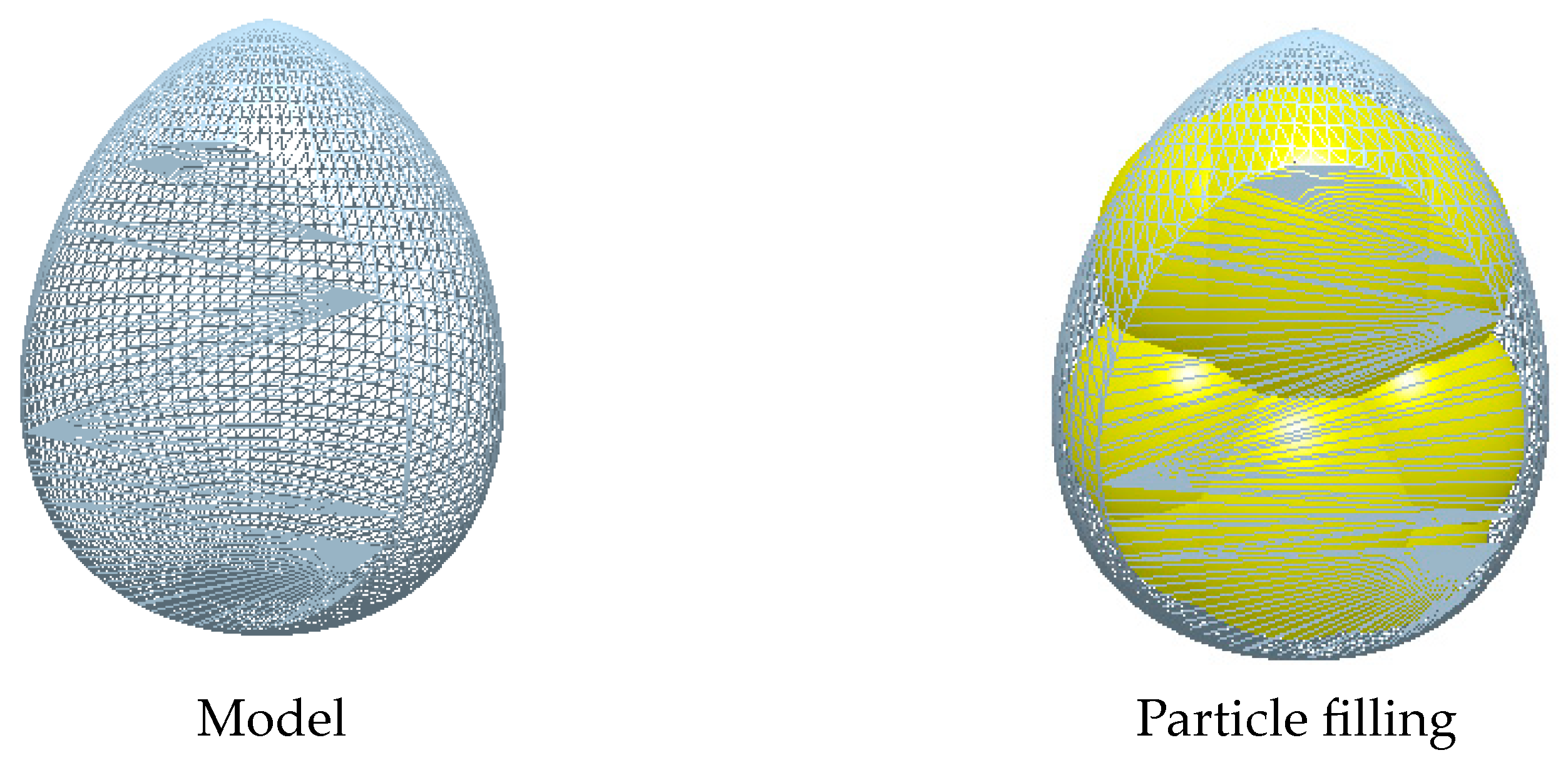
3.1. Simulation and Verification

Figure 8 illustrates the irregular movements of the particles in the hopper under the influence of the stirrer. To demonstrate this effect clearly, the average spacing between the particles and the seed tray was chosen as the indicator to measure the effect of seed disturbance. A curve was then drawn with the average spacing under a time step of 5~9 seconds in the middle period, as shown in Figure 9. It is evident that, in the absence of the seed-stirring device, the distance between the seed and the seed tray is fixed, indicating that the seed is in a static state, and, in the case of the seed-stirring device, the curve fluctuates significantly, indicating that the seed-stirring device can have a disturbing effect on the seeds and avoids their accumulation [37,38,39,40].
To assess the effect of the designed stirring device on the seed-metering device, along with the optimal parameter settings mentioned above, bench tests were conducted using the seeding device both with and without the stirring device, as illustrated in Figure 10. Table 5 displays the experimental results obtained.
Based on the optimal parameter settings, the test results indicate a higher seed discharger missing rate in the absence of the seed-stirring device. The discrete element simulation results, when combined with this finding, demonstrate that seed pile-up affects the seed-filling effect. Thus, the seed-stirring device’s disruptive effect enhances the working performance of the seed-metering device.

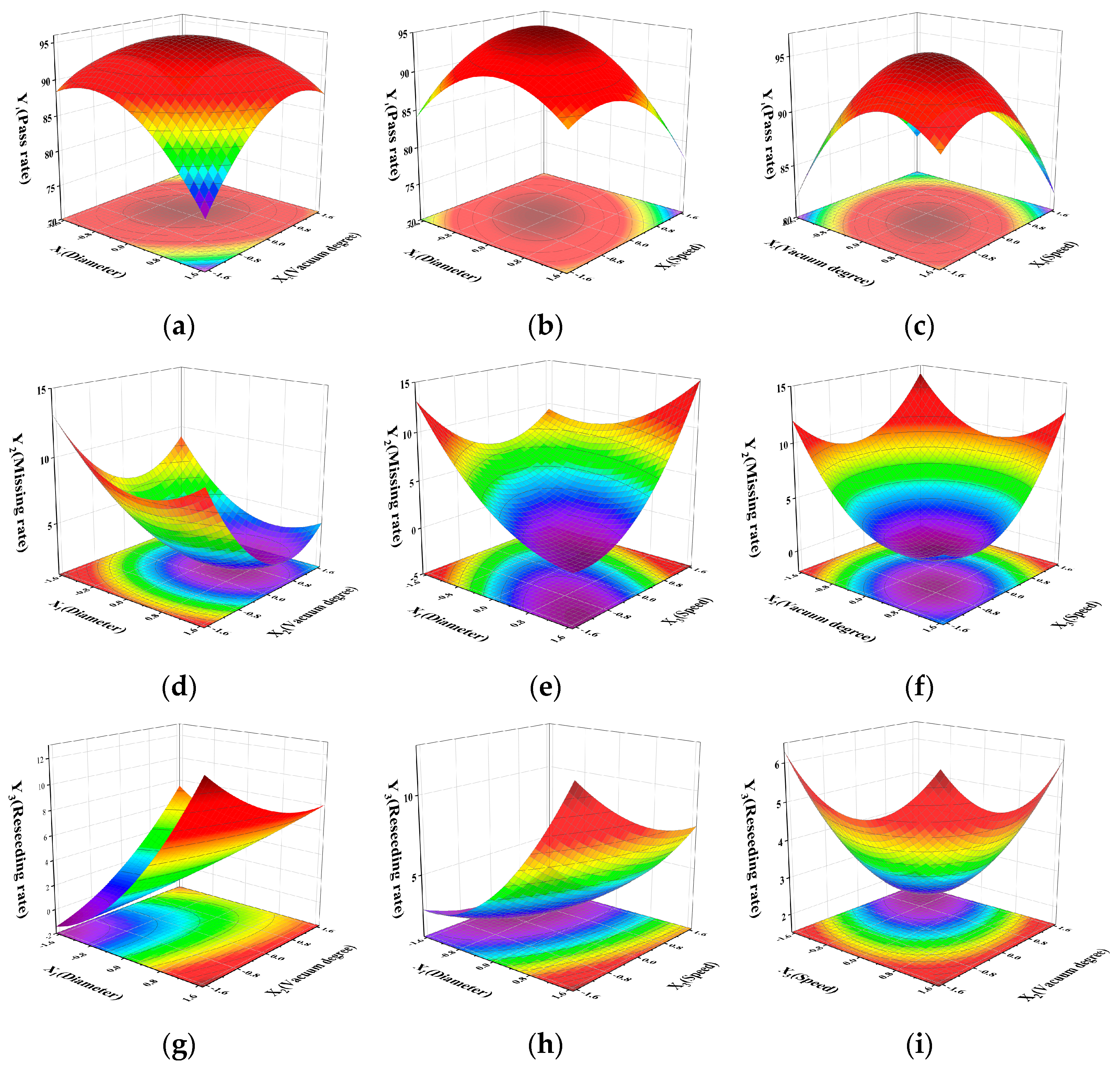
3.2. Analysis of Variance

The bench test program and the results are shown in Table 6.

3.2.1. Pass Rate

The dates from the multifactorial experiments were imported into Design-Expert 13 for analysis. An ANOVA of the pass rate was conducted, and the results are shown in Table 7.
The model p < 0.0001 (<0.01) shows that the regression model of the pass rate is extremely significant, and the regression equation is meaningful. The model misfit term p = 0.3937 (>0.05) is not significant, indicating that the fitting level of the equation is high and significant.
Figure 11a displays a response surface chart illustrating the effect of the interaction between the diameter of the profile holes and the vacuum degree of the negative-pressure chamber on the pass rate. As the diameter of the profile holes and the vacuum degree of the negative-pressure chamber increase, the pass rate initially increases but then decreases. When the diameter of the profile holes is fixed, the pass rate first increases and then decreases as the vacuum in the chamber gradually increases. When the vacuum level in the negative-pressure chamber stabilizes, the pass rate gradually improves with an increase in the profile hole diameter, eventually reaching a peak before decreasing. When the diameter of the profile holes measures between 2.0 and 2.5 mm and the vacuum degree of the negative-pressure chamber ranges from 7.0 to 8.0 kPa, the pass rate reaches its highest point.
Figure 11b displays a response surface chart illustrating the effect of the interaction between the diameter of the profile holes and the speed of the seed-metering device on the pass rate. As the diameter of the profile holes and the speed of the seed-metering device increase, the pass rate first increases and then decreases. When the diameter of the profile holes remains constant, the pass rate initially rises, then falls with the progressive acceleration of the seed-metering device’s discharge. When the seed-metering device’s speed remains stable, the pass rate increases and then decreases as the profile hole’s diameter increases. When the profile holes have a diameter of 2.5~3.0 mm and the speed of the seed-metering device ranges from 30 to 35 r/min, the pass rate reaches its maximum value.
Figure 11c displays a response surface diagram illustrating the influence of the interaction between the vacuum degree of the negative-pressure chamber and the speed of the seed-metering device on the pass rate. As the vacuum degree of the negative-pressure chamber and the speed of the seed-metering device increase, the pass rate initially increases and then decreases. When the vacuum level within the negative-pressure chamber remains constant, the pass rate initially increases and then decreases gradually as the speed of the seed-metering device increases. When the speed of the seed-metering apparatus is steady, the pass rate initially rises and then falls as the vacuum level in the negative-pressure chamber increases. When the negative-pressure chamber reaches a vacuum degree of 6.0~7.0 kPa and the seed-metering device operates at a speed of 25~30 r/min, the pass rate reaches its highest value.

3.2.2. Missing Rate

An ANOVA of the missing rate was conducted, and the results are shown in Table 8.
The model p < 0.0001 (<0.01) shows that the regression model of the missing rate is extremely significant, and the regression equation is meaningful. The model misfit term p = 0.0561 (>0.05) is not significant, indicating that the fitting level of the equation is high and significant.
Figure 11d displays a response surface chart illustrating the effect of the interaction between the diameter of the profile holes and the vacuum degree of the negative-pressure chamber on the missing rate. As depicted in the figure, the missing rate initially decreases and then increases with the increase in the diameter of the profile holes and the vacuum degree of the negative-pressure chamber. As the vacuum degree of the negative-pressure chamber gradually increases, the missing rate decreases when the diameter of the profile holes in the seed tray is fixed. When the vacuum degree of the negative-pressure chamber stabilizes, the missing rate first decreases and then slightly rises with an increase in the diameter of the profile holes.
Figure 11e displays the response surface chart illustrating the interaction between the diameter of the profile holes and the speed of the seed-metering device on the missing rate. The figure indicates that the missing rate initially decreases and then increases with an increase in the diameter of the profile holes and the speed of the seed-metering device. As the speed of the seed-metering device increases, the missing rate of the diameter of the profile holes initially decreases before increasing again. Similarly, when the diameter of the profile holes is increased, the missing rate gradually decreases once the rotational speed of the seed expulsion axis reaches a steady state.
Figure 11f displays a response surface chart illustrating the interaction between the negative-pressure chamber and the speed of the seed-metering device on the missing rate. The figure shows that the missing rate decreases and then increases as the vacuum degree of the negative-pressure chamber and the speed of the seed-metering device increase. As the speed of the seed-metering device gradually increases, the missing rate decreases until it reaches a steady state. However, as the vacuum degree of the negative-pressure chamber increases, the missing rate also increases. As the speed of the seed-metering device stabilizes, the missing rate initially decreases but then increases as the vacuum degree of the negative-pressure chamber increases.

3.2.3. Reseeding Rate

An ANOVA of the reseeding rate was conducted, and the results are shown in Table 9.
The model p = 0.0009 (<0.01) shows that the regression model of the reseeding rate is extremely significant, and the regression equation is meaningful. The model misfit term p = 0.0939 (>0.05) is not significant, indicating that the fitting level of the equation is high and significant.
Figure 11g displays a response surface chart illustrating the interaction between the diameter of the profile holes and the vacuum degree of the negative-pressure chamber on the reseeding rate. The reseeding rate initially decreases and then increases with the increase in the diameter of the profile holes and the vacuum degree of the negative-pressure chamber. As the vacuum degree of the negative-pressure chamber increases, the reseeding rate decreases when the diameter of the profile hole is fixed. Conversely, when the vacuum degree of the negative-pressure chamber stabilizes, the reseeding rate increases as the diameter of the profile holes increases.
Figure 11h displays a response surface chart illustrating the interaction between the diameter of the profile holes and the speed of the seed-metering device on the reseeding rate. The surface plot indicates that the reseeding rate initially decreases and then increases with an increase in the diameter of the profile holes and the speed of the seed-metering device. As the speed of the seed-metering device increases, the reseeding rate initially decreases before increasing again when the diameter of the profile holes is fixed. As the diameter of the profile holes increases, the reseeding rate gradually decreases once the speed of the seed-metering device reaches a steady state.
Figure 11i displays a response surface chart illustrating the interaction between the vacuum degree of the negative-pressure chamber and the speed of the seed-metering device on the reseeding rate. The figure indicates that the reseeding rate decreases and then increases as the vacuum degree of the negative-pressure chamber and the speed of the seed-metering device increase. As the speed of the seed-metering device increases gradually, the reseeding rate decreases. Once the speed reaches a steady state, the reseeding rate initially decreases and then increases. Similarly, when the speed of the seed-metering device reaches a steady state, the reseeding rate gradually increases with an increase in the vacuum degree of the negative-pressure chamber.

3.3. Optimal Parameter Verification Test

3.3.1. Practical Tests

The date analysis software Design-Expert 13 was used to obtain the rounded optimization results for each working parameter. The pass rate was 95.95%, the missing rate was 0.5%, and the reseeding rate was 3.55% when the profile holes’ diameter measured 2.5 mm, the negative-pressure chamber’s vacuum degree was 8.0 kPa, and the seed-metering device operated at 28 r/min.
Following the optimization results, the test factors were selected as follows: the diameter of the profile holes of the seed tray was 2.5 mm, the vacuum degree of the negative-pressure chamber was 8.0 kPa, the speed of the seed-metering device was 28 r/min, and the other factors remained unchanged. The test was repeated three times, and the average value was obtained as the final control test result. The actual index and the theoretical results were compared, as shown in Table 10. The table shows that the error differences between the theoretical and actual tests are 0.64%, 0.25%, and 0.39%. These errors fall within a reasonable range according to the evaluation standard for sowing machinery.

3.3.2. Field Test

In order to evaluate the overall performance of the seeder, a prototype must be created and field-tested. To ensure the cleanliness of the plot seeder when replacing the seeds to examine different test factors, two sorghum colors of the same size were selected, as depicted in Figure 12; for the sowing test, the A variety (Suiza No. 7) was denoted by red, as shown on the left side, and the B variety (Liaoza No. 11) was denoted by white, on the right side. The test plots were divided, as shown in Figure 13, and the seeds were planted accordingly.
For the performance comparison, we selected a duckbill seeder, which is widely used in small-scale planting due to its simple structure, low cost, and versatility. According to the best combination of parameters obtained, the seeder speed should be between 3.6 and 5.4 km/h. The results were recorded manually at the end of the test. The performance parameters were measured at the same forward speed. The field trials of the two seeders are shown in Figure 14, and the results are presented in Table 11.
There were nine plots in the test field. The seeds needed to be replaced eight times. Each plot required 250 ✕ 8 plants to be sown, resulting in a total of 18,000 plants. The seed-mixing phenomenon occurred zero times, indicating that the seeder meets the requirements of plot seeding. According to Table 8, the comparison shows that the oil–electric hybrid air suction sorghum plot seeder outperforms the duckbill seeder. The oil–electric hybrid pneumatic seeder for sorghum plots meets the necessary performance standards for effective sorghum seeding and agronomy. The monitoring system’s error is less than 7.19%, demonstrating that it has reliable performance and can be applied to practical work.
In summary, the aims of the motorized suction seed-metering device are to prevent the ground wheel from slipping when planting, enhance the quality of sowing, and minimize the loss of labor efficiency caused by seed thinning when using traditional mechanical seed-metering devices. The fuel tractor’s power and traction reduce the physical exertion required for walking and ensure the stability of the fan and motor operation. This study provides support for the development of small-scale new energy seeding machinery.

4. Conclusions

We conclude with the following:
(1) Taking sorghum as the research object and a plot test field as the environment, a type kind of oil–electric hybrid pneumatic sorghum plot seeder was designed. The seeder adopts an oil–electric hybrid drive mode to provide power for operation and seeding and to the fan.
(2) The key parameters of the seed-metering device were determined by analyzing the forces and kinematics of sorghum in the device. The seed trays have a diameter of 240 mm and contain 24 profile holes with a diameter of 1.5 mm. The tray thickness is 2 mm. To solve the issue of seed accumulation, a seed-stirring device was designed, and the effect of the seed-stirring device on seed adsorption in the seed tray was verified using a discrete element simulation combined with bench tests.
(3) A bench test was conducted on the designed seed-metering device, resulting in the acquisition of the best parameter combination after rounding. The diameter of the profile holes of the seed tray measured 2.5 mm. The negative-pressure chamber’s vacuum degree was 8.0 kPa, while the seed-metering device ran at 28 r/min. The pass rate achieved was 95.95%, with a missing rate of 0.5% and a reseeding rate of 3.55%. A control experiment was conducted on the optimized outcomes, with deviations of 0.64%, 0.25%, and 0.39%, respectively.
(4) After analyzing the optimal parameter combinations, we parameterized the field trials and compared the performance of the oil–electric hybrid air suction sorghum plot planter with that of the duckbill planter at different forward speeds. The hybrid air suction sorghum plot seeder achieved an average pass rate of 94.41%, a missing rate of 2.30%, and a reseeding rate of 3.29%. In contrast, the duckbill planter had an average pass rate of 86.94%, a missing rate of 3.78%, and a reseeding rate of 9.27%. The missing and reseeding issues were partially resolved, and the average error of the missing monitoring system was 5.64%, which falls within the acceptable range according to the evaluation standards of the seeding machinery industry. The optimal parameter configuration derived from the analysis showed minimal differences. There were no instances of mixing when the seed was replaced to examine different factors, indicating that the oil–electric hybrid air suction sorghum plot seeder meets the seeding requirements for sorghum.

Author Contributions

Conceptualization, X.Y. and C.H.; methodology, X.Y. and G.T.; software, X.Y.; validation, X.Y., G.T., S.Y., and C.H.; formal analysis, X.Y.; investigation, X.Y., G.T. and C.H; resources, G.T. and C.H.; data curation, X.Y.; writing—original draft preparation, X.Y. and G.T..; writing—review and editing, X.Y. and C.H; visualization, X.Y.; supervision, G.T. and C.H.; project administration, X.Y.; funding acquisition, S.Y. and Y.L. All authors have read and agreed to the published version of the manuscript.

Funding

This research was funded by the National Natural Science Foundation, grant number: 52275246, the Key Research and Development Plan Project of Heilongjiang Province, grant number: 2022ZX05B02.

Data Availability Statement

The data will be available through contacting the corresponding author.

Conflicts of Interest

The authors declare no conflicts of interest.

References

  1. Dornbos, D.L. Production environment and seed quality. In Seed Quality; CRC Press: Boca Raton, FL, USA, 2020; pp. 119–152. [Google Scholar]
  2. Howard, P.H. Recent changes in the global seed industry and Digital Agriculture Industries. 2022. Available online: https://philhoward.net/2023/01/04/seed-digital/ (accessed on 1 February 2023).
  3. Golubev, V.; Kudryavtsev, A.; Firsov, A.; Safonov, M. Technique of agrotechnical field experiment. Agric. Mach. Technol. 2017, 4, 43–48. [Google Scholar] [CrossRef]
  4. Lian, Z.; Wang, J.; Yang, Z.; Shang, S. Development of plot-sowing mechanization in China. Trans. Chin. Soc. Agric. Eng. 2012, 28, 140–145. [Google Scholar]
  5. Lavrov, A.; Smirnov, I.; Litvinov, M. Justification of the construction of a self-propelled selection seeder with an intelligent seeding system. In MATEC Web of Conferences; EDP Sciences: Les Ulis, France, 2018; Volume 224, p. 05011. [Google Scholar] [CrossRef]
  6. Litvinov, M.A.; Moskovskiy, M.N.; Pakhomov, I.V.; Smirnov, I.G. Interface and software for the system of automatic seeding of grain crops. In Proceedings of the 2019 IEEE East-West Design & Test Symposium. EWDTS, Batumi, Georgia, 13–16 September 2019; pp. 1–4. [Google Scholar] [CrossRef]
  7. Liu, S.G.; Ma, Y.F. Development History, Status and Trends of Plot Seeder. Appl. Mech. Mater. 2013, 268, 1966–1969. [Google Scholar] [CrossRef]
  8. Okeyo, S.O.; Ndirangu, S.N.; Isaboke, H.N.; Njeru, L.K. Determinants of sorghum productivity among small-scale farmers in Siaya County, Kenya. Afr. J. Agric. Res. 2020, 16, 722–731. [Google Scholar] [CrossRef]
  9. Beckman, J.; Ivanic, M.; Jelliffe, J. Market impacts of Farm to Fork: Reducing agricultural input usage. Appl. Econ. Perspect. Policy 2022, 44, 1995–2013. [Google Scholar] [CrossRef]
  10. Gao, X.; Cui, T.; Zhou, Z.; Yu, Y.; Xu, Y.; Zhang, D.; Song, W. DEM study of particle motion in novel high-speed seed metering device. Adv. Powder Technol. 2021, 32, 1438–1449. [Google Scholar] [CrossRef]
  11. Liu, R.; Liu, Z.; Zhao, J.; Lu, Q.; Liu, L.; Li, Y. Optimization and Experiment of a Disturbance-Assisted Seed Filling High-Speed Vacuum Seed-Metering Device Based on DEM-CFD. Agriculture 2022, 12, 1304. [Google Scholar] [CrossRef]
  12. Kovács, P.; Casteel, S.N. Evaluation of a high-speed planter in soybean production. Agron. J. 2023, 115, 1174–1187. [Google Scholar] [CrossRef]
  13. Timene, A.; Djalo, H. Design of a five-bar duckbill-type mechanism for sorghum transplanting. J. Agric. Eng. 2023, 54, 1473. [Google Scholar] [CrossRef]
  14. Wang, H.; Sun, X.; Li, H.; Fu, J.; Zeng, X.; Xu, Y.; Wang, Y.; Liu, H.; Lü, Z. Design and parameter optimization of a finger clip plate garlic seed-metering device based on EDEM. Agronomy 2022, 12, 1543. [Google Scholar] [CrossRef]
  15. Zhao, H.; Zhang, D.; Yang, L.; Cui, T.; Song, W.; He, X.; Wu, H.; Dong, J. Optimal design and experiment of critical components of hand-pushing corn plot precision planter. Agriculture 2022, 12, 2103. [Google Scholar] [CrossRef]
  16. Dharmendra, K.R.; Venkat, R. Performance evaluation of manually operated single row cotton planter. Int. J. Chem. Stud. 2020, 8, 130–134. [Google Scholar] [CrossRef]
  17. Tang, H.; Xu, C.; Wang, Z.; Wang, Q.; Wang, J. Optimized design, monitoring system development and experiment for a long-belt finger-clip precision corn seed metering device. Front. Plant Sci. 2022, 13, 814747. [Google Scholar] [CrossRef] [PubMed]
  18. Wang, M.; Liu, Q.; Ou, Y.; Zou, X. Numerical simulation and verification of seed-filling performance of single-bud billet sugarcane seed-metering device based on EDEM. Agriculture 2022, 12, 983. [Google Scholar] [CrossRef]
  19. Xu, J.; Hou, J.; Wu, W.; Han, C.; Wang, X.; Tang, T.; Sun, S. Key structure design and experiment of air-suction vegetable seed-metering device. Agronomy 2022, 12, 675. [Google Scholar] [CrossRef]
  20. Tang, H.; Xu, F.; Xu, C.; Zhao, J.; Wang, Y.-J. The influence of a seed drop tube of the inside-filling air-blowing precision seed-metering device on seeding quality. Comput. Electron. Agric. 2023, 204, 107555. [Google Scholar] [CrossRef]
  21. Haitao, C.; Hongfei, W.; Yecheng, W.; Naiyu, S.; Zhipeng, W.; Yukuan, D. Design and experiment of three-leaf type air-suction seed meter with automatic clear and replace seeds features for soybean plot test. Trans. Chin. Soc. Agric. Mach. 2020, 51, 75–85. [Google Scholar] [CrossRef]
  22. Xiong, D.; Wu, M.; Xie, W.; Liu, R.; Luo, H. Design and experimental study of the general mechanical pneumatic combined seed metering device. Appl. Sci. 2021, 11, 7223. [Google Scholar] [CrossRef]
  23. Karayel, D.; Güngör, O.; Šarauskis, E. Estimation of optimum vacuum pressure of air-suction seed-metering device of precision seeders using artificial neural network models. Agronomy 2022, 12, 1600. [Google Scholar] [CrossRef]
  24. Xing, H.; Wang, Z.; Luo, X.; He, S.; Zang, Y. Mechanism modeling and experimental analysis of seed throwing with rice pneumatic seed metering device with adjustable seeding rate. Comput. Electron. Agric. 2020, 178, 105697. [Google Scholar] [CrossRef]
  25. Fangyan, W.; Liang, Y.; Hongti, W. Design and Test of Electric Driving Pneumatic Carrot Planter in Greenhouse. Trans. Chin. Soc. Agric. Mach. 2022, 53, 64–74. [Google Scholar] [CrossRef]
  26. Qinghui, L.; Qin, L.; Guangxin, J.; Xiaobao, Q.; Wei, S.; Jinwen, Z. Design and Test of Ginseng Precision Seeder with Ditching and Seeding Monomer Type. Trans. Chin. Soc. Agric. Mach. 2022, 53, 72–82. [Google Scholar] [CrossRef]
  27. Chen, J.; Zhang, H.; Pan, F.; Du, M.; Ji, C. Control system of a motor-driven precision no-tillage maize planter based on the CANopen protocol. Agriculture 2022, 12, 932. [Google Scholar] [CrossRef]
  28. Yu, Y.; Hu, Y.; Shang, S.; Diao, L.; Ge, R.; Zhang, X. Design of motor-driven precision seed-metering device with improved fuzzy PID controller for small peanut planters. Int. J. Agric. Biol. Eng. 2023, 16, 136–144. [Google Scholar] [CrossRef]
  29. Hou, Y.; Wu, Z.; Cai, X.; Dong, Z. Research on Fault Diagnosis and Prediction Method about Driving Motor for Seeding Metering of Plot Seeder Based on SVMs Classification and Regression. IOP Conf. Ser. Earth Environ. Sci. 2020, 474, 032012. [Google Scholar] [CrossRef]
  30. Krutz, G.; Thompson, L.; Claar, P. Design of Agricultural Machinery; John Wiley and Sons: Hoboken, NJ, USA, 1984. [Google Scholar]
  31. Krutz, G.; Thompson, L.; Claar, P. Solutions Manual to Accompany Design of Agricultural; Wiley: New York, NY, USA, 1984. [Google Scholar]
  32. Qiu, S.; Yu, Y.; Feng, Y.; Tang, Z.; Cui, Q.; Yuan, X. Crushing Characteristics of Sorghum Grains Subjected to Compression and Impact Loading at Different Moisture Contents. Agriculture 2022, 12, 1422. [Google Scholar] [CrossRef]
  33. Tabal, R.; Amongo, R.; Quilloy, E.; Peralta, E. Development of a single-row push type plot seeder with mechatronic seed feeding device for corn. Zea mays L. field breeding experiment. IOP Conf. Ser. Earth Environ. Sci. 2022, 977, 012067. [Google Scholar] [CrossRef]
  34. Aduov, M.; Nukusheva, S.; Tulegenov, T.; Volodya, K.; Uteulov, K.; Karwat, B.; Bembenek, M. Experimental Field Tests of the Suitability of a New Seeder for the Soils of Northern Kazakhstan. Agriculture 2023, 13, 1687. [Google Scholar] [CrossRef]
  35. Chen, Y.; Cheng, Y.; Chen, J.; Zheng, Z.; Hu, C.; Cao, J. Design and experiment of the buckwheat hill-drop planter hole forming device. Agriculture 2021, 11, 1085. [Google Scholar] [CrossRef]
  36. Cheng, X.; Li, H.; He, J.; Wang, Q.; Lu, C.; Wang, Y.; Wang, C.; Wang, C.; Lou, S. Optimization of operating parameters of seeding device in plot seeder with seeding control system. Int. J. Agric. Biol. Eng. 2021, 14, 83–91. [Google Scholar] [CrossRef]
  37. Cortez, J.W.; Anghinoni, M.; Arcoverde, S.N. Seed metering mechanisms and tractor-seeder forward speed on corn agronomic components. Eng. Agrícola 2020, 40, 61–68. [Google Scholar] [CrossRef]
  38. Dongwei, W.; Jiasheng, W.; Shuqi, S. Design and Experimental Study on Seed Metering Device of Peanut Plot Seeder. Сельскoхoзяйственные 2019, 4, 38–41. [Google Scholar] [CrossRef]
  39. Li, H.; Zhao, C.; Yan, B.; Ling, L.; Meng, Z. Design and Verification of the Variable Capacity Roller-Wheel Precision Rice Direct Seed-Metering Device. Agronomy 2022, 12, 1798. [Google Scholar] [CrossRef]
  40. Lopes, A.G.C.; Correia, T.; Taveira, W.; Pereira, G.G.; Souza, A. Soybean performance in grouped and conventional sowing with pneumatic seeder at different operational speeds. Rev. Agric. Neotrop. 2021, 8, e6721. [Google Scholar] [CrossRef]
Figure 1. Structure diagram of oil-electric hybrid air-suction sorghum plot seeder. 1. Diesel engine; 2. Generator; 3. Seed-metering device; 4. Fan; 5. Battery; 6. Electric control box; 7. Suppression wheel; 8. Seed clearing mechanism; 9. Covering device; 10. Motor; 11. Missed monitoring system; 12. Ditch opener.
Agriculture 14 00432 g001
Figure 2. Schematic diagram of the seed-metering device. (a) Overall components composition; (b) Regional distribution of seed tray.1. Seal ring; 2. Pressure plate; 3. Top cover; 4. Left shell; 5. Negative pressure interface; 6. Seed scraper; 7. Right shell; 8. Seeding shaft; 9. Seed guide wheel; 10. Seed tray. I. Seed-filling area; II. Seed-carrying area; III. Seed-scraping area; IV. Seed-dropping area.
Agriculture 14 00432 g002
Figure 3. Analysis diagram of seed stress in the filling area. (a) XY plane; (b) YZ plane.
Agriculture 14 00432 g003
Figure 4. Schematic diagram of seed stirring device. I. Seed mixing pin; II. Adsorbed seed; III. “Disturbed” seed; IV. Seed guide wheel; V. Groove.
Agriculture 14 00432 g004
Figure 5. Workflow chart of the seeding control and monitoring system.
Agriculture 14 00432 g005
Figure 6. Test bench structure schematic. 1. Monitoring device; 2. Fixed bracket; 3. Seed-metering device; 4. Seed box; 5. Motor; 6. Belt; 7. Oil circuit system; 8. Wind system; 9. Altitude adjustment device.
Agriculture 14 00432 g006
Figure 7. Sorghum seed model.
Agriculture 14 00432 g007
Figure 8. Discrete element simulation mixing effect.
Agriculture 14 00432 g008
Figure 9. Curve of average spacing and time between particles and seed tray.
Agriculture 14 00432 g009
Figure 10. Seed stirring device test.
Agriculture 14 00432 g010
Figure 11. Response Surface Chart. (ac). Response surface of pass rate under the interaction of three factors. (df). Response surface of missing rate under the interaction of three factors. (gi). Response surface of reseeding rate under the interaction of three factors.
Agriculture 14 00432 g011
Figure 12. Schematic of sorghum seed.
Agriculture 14 00432 g012
Figure 13. Schematic diagram of the test field. (a) Overall status of the test field; (b) Status of test field unit.
Agriculture 14 00432 g013
Figure 14. Field plots of the field test. (a) Oil-electric hybrid air-suction sorghum plot seeder; (b) Duckbill seeder.
Agriculture 14 00432 g014
Table 1. Parameters of oil–electric hybrid air suction sorghum plot seeder.
ProjectParameter
Size/mm1500 × 450 × 750
Mass/kg100
Power/kW9.52
Number of rows1
Plant spacing/mm20~150
Operating speed/km/h3.6~5.4
Sowing depth/mm0~50
Table 2. Sorghum seed size measurements and calculations.
MaximumMinimumAverage ValueStandard Deviation
Length/mm4.871.173.670.04
Width/mm5.581.842.390.06
Height/mm5.392.384.300.04
Sphericity/%97.9372.4378.041.02
Table 3. Test-factor-level encoding table.
XiDiameter
X1/(mm)
Vacuum Degree
X2/(kPa)
Speed
X3/(r/min)
γ3.89.364 ≈ 9.446.8
+13.58.040
02.56.030
−11.54.020
−γ0.82.636 ≈ 2.613.182 ≈ 13.2
Δj1.352.010.0
Table 4. Physical parameter settings.
ProjectPoisson’s RatioShear
Modulus
(Pa)
Density
(kg·m−3)
Elastic Recovery Factor
(With Sorghum)
Sorghum0.361.25 × 10812000.3230.4330.0554
Seed tray0.277.40 × 101076000.7230.4760.0322
Seed mixing Pin0.190.25 × 1058000.2060.6260.0177
Table 5. Seed stirring device test results.
TypePass Rate
Y1 (%)
Missing Rate
Y2 (%)
Reseeding Rate
Y3 (%)
Absence90.45.653.95
Presence95.310.753.94
Table 6. Test protocol and data results.
No.Experimental FactorsTest Metrics
Diameter
X1/(mm)
Vacuum Degree
X2/(kPa)
Speed
X3/(r/min)
Pass
Rate
Y1 (%)
Missing Rate
Y2 (%)
Reseeding
Rate
Y3 (%)
11.54.020.090.258.760.99
23.54.020.086.894.518.6
31.58.020.090.174.745.09
43.58.020.093.761.025.22
51.54040.092.96.150.95
63.54.040.086.219.594.20
71.58.040.090.715.573.72
83.58.040.088.037.134.84
91.26.030.090.559.100.35
103.86.030.086.952.0311.02
112.52.630.087.379.573.06
122.59.430.090.333.915.76
132.56.013.291.543.215.25
142.56.046.886.4210.523.06
152.56.030.095.872.491.64
162.56.030.095.361.593.05
172.56.030.094.243.632.13
182.56.030.093.22.913.89
192.56.030.095.041.433.53
202.56.030.095.52.531.97
212.56.030.094.253.032.72
222.56.030.095.341.073.59
232.56.030.098.20.930.87
Table 7. ANOVA analysis of variance of pass rate.
Source of VarianceSum of SquaresDfF-Valuep-Value
Model250.47913.46<0.0001
X116.9118.170.0134
X29.5114.600.0514
X310.2514.960.0443
X1×215.0217.260.0184
X1 X311.5215.570.0346
X2×36.4113.100.1018
X1263.55130.73<0.0001
X2261.32129.650.0001
X3258.49128.280.0001
Residuals26.8813--
Lack of Fit11.4551.190.3937
Pure Error15.438--
Cor Total277.3522--
Table 8. ANOVA analysis of variance of missing rate.
Source of VarianceSum of SquaresDfF-Valuep-Value
Model190.55911.82<0.0001
X116.1719.030.0101
X229.49116.470.0014
X334.49119.260.0007
X1×20.2310.130.7271
X1 X321.03111.740.0045
X2×32.5011.390.2588
X1217.5019.770.0080
X2234.10119.040.0008
X3236.19120.210.0006
Residuals23.2813
Lack of Fit16.0053.520.0561
Pure Error7.288
Cor Total213.8422
Table 9. ANOVA analysis of variance of reseeding rate.
Source of VarianceSum of SquaresDfF-Valuep-Value
Model113.4097.200.0009
X166.14137.80<0.0001
X25.5113.150.0995
X37.1414.080.0645
X1×211.5416.600.0234
X1 X31.4210.810.3841
X2×30.9010.520.4849
X1214.3518.200.0133
X223.9612.270.1562
X322.6611.520.2392
Residuals22.7513
Lack of Fit14.4952.810.0939
Pure Error8.268
Cor Total136.1422
Table 10. Test comparison and optimization results.
Test NamePass Rate
Y1 (%)
Missing Rate
Y2 (%)
Reseeding Rate
Y3 (%)
Optimized results95.950.53.55
Practical tests95.310.753.94
Test error0.640.250.39
Table 11. Field test results.
No.Forward Speed
(km/h)
Pass Rate
Y1 (%)
Missing Rate
Y2 (%)
Reseeding Rate
Y3 (%)
Missed Monitoring Rate
(%)
Monitoring Error
(%)
Plot seeder13.894.911.533.561.647.19
24.294.821.743.441.824.60
34.694.851.733.421.835.78
45.094.162.852.992.994.91
55.493.273.673.063.885.72
Ave.4.5894.412.303.292.545.64
Duckbill Seeder13.889.722.637.65--
24.288.822.748.44--
34.688.752.738.52--
45.084.164.8510.99--
55.483.275.9710.76--
Ave.4.5886.943.789.27--
Disclaimer/Publisher’s Note: The statements, opinions and data contained in all publications are solely those of the individual author(s) and contributor(s) and not of MDPI and/or the editor(s). MDPI and/or the editor(s) disclaim responsibility for any injury to people or property resulting from any ideas, methods, instructions or products referred to in the content.

