Article

Design and Experiment for Inter-Vehicle Communication Based on Dead-Reckoning and Delay Compensation in a Cooperative Harvester and Transport System

1
Key Laboratory of the Ministry of Education of China for Key Technologies for Agricultural Machine and Equipment, South China Agricultural University, Guangzhou 510642, China
2
Guangdong Provincial Key Laboratory for Agricultural Artificial Intelligence (GDKL-AAI), Guangzhou 510642, China
3
Guangdong Laboratory for Lingnan Modern Agriculture, Guangzhou 510642, China
*
Author to whom correspondence should be addressed.
Agriculture 2022, 12(12), 2052; https://doi.org/10.3390/agriculture12122052
Submission received: 21 October 2022 / Revised: 27 November 2022 / Accepted: 27 November 2022 / Published: 29 November 2022
(This article belongs to the Section Agricultural Technology)

Abstract

:
To achieve high-frequency and effective inter-vehicle communication between harvesters and transport vehicles during cooperative harvesting, a protocol for wireless communication was designed by analyzing actual communication requirements. Two different wireless communication modes (radio and 4G) were selected for the hardware design; then, a Kalman Filter was designed based on real-time Dead-reckoning and inter-vehicle Communication data after delay Compensation (KFDCC). Finally, the relative longitudinal deviation between two vehicles was obtained and updated steadily at a 10 Hz frequency. By using the relative longitudinal deviation of two vehicles, calculated after aligning the UTC stamp with the local GNSS data from the harvester and transport vehicle as a comparative metric, accuracy evaluation experiments were conducted regarding radio and 4G. The maximum absolute errors of the KFDCC output value were 0.03783 and 0.07381 m, respectively, and the mean square errors were 0.00392 and 0.01317 m, respectively. Compared with systems without the KFDCC method, the mean square errors were reduced by 88.76% and 90.60%, respectively. The KFDCC method can also effectively solve the problems of data delay, packet loss, blockage, error, and so on, in wireless communication, and has short-time breakpoint endurance capabilities. Field experiments showed that the proposed method can provide accurate data support for the dynamic alignment and unloading processes of harvesters and transport vehicles, and it can also provide algorithmic support for real-time communication data fusion between different wireless communication modes. Overall, the inter-vehicle communication mode and data-processing method designed in this paper have good effects and adaptability, and they can guarantee that the whole process of autonomous harvesting operates properly.

1. Introduction

With the steady progress of urbanization and the continuous transfer of rural labor, shortages in agricultural labor have become increasingly prominent [1]. In this context, methods of improving agricultural production efficiency and resource utilization, reducing labor input and reduce labor intensity have become research hotspots. At this time, the emergence of the concept of “whole-process, all-weather unmanned farm” has become an important development direction for future agriculture. [2,3]. In the harvesting process of the unmanned rice farm, the harvester needs to work together with the transport vehicle autonomously and unload the grain accurately; the prerequisite for this process is effective and timely data exchange between them. Therefore, it is of great significance to research the communication and data processing methods of collaborative navigation to realize the whole process of autonomous harvesting.

1.1. Literature Review

Currently, multi-machine cooperation technology has a wide range of application scenarios in the fields of vehicles, robots and UAVs. As a result, many scholars have conducted research on the communication between multi-machine cooperation. Peng Xinrong (2010) from Shanghai Jiao Tong University proposed a multi-vehicle cooperative communication protocol based on RR-ALOHA, adopted the Digi XBee-Pro module to realize workshop communication, and they studied and tested cooperative driving in typical scenarios such as convoys, overtaking, and intersections [4]. Alshbatat et al. (2010) of the University of Western Michigan proposed the DOLSR (directional optimized link state routing) protocol based on the optimized link state routing (OLSR) protocol, using the flight state information provided by the UAV directional antenna, which improves the data throughput and reduces the end-to-end delay [5]. Shen Zhongyu et al. (2013) from Nanjing Normal University designed a smart car control system based on ARM Cortex-M3 and designed an on-board, self-organizing wireless communication network using ZigBee to achieve cooperative control and formation control over multiple smart cars [6]. Zhang et al. (2016) of Shanghai university designed an intelligent car control system based on Arduino and a self-organizing wireless network based on XBee, which realized the centralized control of the upper computer and could control vehicle speed adjustment, vehicle distance adjustment, vehicle queuing and so on [7]. Rosati et al. (2016) of the Swiss Federal Institute of Technology used GPS information and considered the relative speed between UAVs to propose a prediction-based optimized link state routing (OLSR) protocol, and they used it for UAV self-driving. By organizing the network, the data throughput can be improved, and the packet loss rate can be effectively reduced [8]. Hayato Yajima et al. (2019) proposed a yielding system that enabled vehicles to decide to yield the right of way depending on the traffic on the road. They used the 700 MHz band-based ARIB STD-T 109 protocol for inter-vehicle communication [9]. Takanori Nakazawa et al. (2020) applied the Content Centric Networking (CCN) caching function to inter-vehicle communications. The results showed that it could reduce the average number of hops of data packets and improve the content acquisition success rate [10].
With the continuous development and progress of agricultural machinery navigation technology, cooperative operation has begun to show great demand in agricultural machinery navigation. Some scholars have studied the cooperative operation of agricultural machinery and effected communication between cooperative agricultural machinery. Zhu et al. (2009) from China Agricultural University designed a master–slave cooperative control scheme to realize the development of a two-tractor platooning system. In order to realize inter-machine communication, YRM-211T and YRM-311 wireless data transmission modules produced by the YAESU Company were adopted [11]. Zhang et al. (2010) from the Karlsruhe Institute of Technology in Germany designed a master–slave navigation system for tractors. The XBee-Pro wireless data transmission radio developed by the MaxStream company was adopted to realize the point-to-point connection between the main engine and the slave engine in a 2.4 ghz frequency band. In theory, it can achieve a data throughput of 250 kbps, a transmission distance of 1.6 km under open conditions, and a data update frequency every 100 ms [12]. Wang Zhiqing (2014) from Nanjing Agricultural University designed an autonomous following control system for agricultural vehicles, which used a UTC-1212 wireless transmission module to realize wireless communication between the guide vehicle and the following vehicle, as well as to monitor the driving state information of the two vehicles [13]. Zhang et al. (2016) from Hokkaido University in Japan designed a tractor navigation system based on a “Leader-Follower” algorithm according to the “FOLLOW” algorithm [14]. The server/client structure was adopted to coordinate two tractors, and data interaction between the server and client was conducted through Bluetooth. The interaction frequency and control frequency of the data frames were both 5 Hz [15]. Bai Xiaoping et al. (2017) from the Shenyang Institute of Automation, Chinese Academy of Sciences, designed a harvester group cooperative navigation method based on a leader-follower structure, wherein a group of harvesters composed of one leader and three followers drove in a straight line in a field, and the communication between them was realized through a short-range, wireless, self-organizing network [16]. Li Shichao et al. (2017) from China Agricultural University designed a multi-machine cooperative navigation and communication system based on TD-LTE to realize communication between the server and the vehicle terminal. Four LOVOL tractors were used as the test platform; the transmission frequency of the state information of each farm machine was 5 Hz, and a stability test of the system was conducted [17]. Li et al. (2019) from China Agricultural University designed a following master–slave automatic driving operation system for agricultural machinery. A wireless data transmission unit produced by the Shenzhen Avelin company was applied to inter-vehicle communication. Its working frequency was 433 MHz, and the data frame was sent every 200 ms. The control frequency of the navigation system was 5 Hz. The subsequent tests showed that the slave could follow the host autonomously at a speed of 0.8 m/s [18]. Zhang Wenyu et al. (2021) from South China Agricultural University designed a control method to record the longitudinal relative position of the harvester and transport vehicle based on the position-velocity coupling principle, and they verified the actual field harvest operation. The communication between the harvester and transport vehicle used two E34-DTU(2G4D20) full-duplex data transmission radio modems from the EBYTE Company; the working frequency was 2.4 GHz, and the frequency used to send and receive data frames was 10 Hz [19]. Chen Jin et al. (2022) from Jiangsu University designed wireless communication for the combine harvester group by using the 2.4 GHz LoRa technology. Overall success rates of communication were 99.3%, and 92.5% under the “Report” and “Request” modes, respectively. The average response time was 123.07 ms [20].
According to the literature, the wireless communication methods that can be used for the cooperative operation of agricultural machinery are summarized [21,22] in Table 1.

1.2. Objectives of the Research

From the literature [4,5,6,7,8,9,10], it is known that research on multi-machine cooperative communication problems for vehicles, UAVs, and other aspects has made great progress. As for large equipment such as agricultural machinery, due to its special navigation operation characteristics, application scenarios, and other factors, it is somewhat different from vehicles, robots, UAVs, and other fields, and many methods can only be referred, but not directly applied. From the literature [11,12,13,14,15,16,17,18,19,20], it can be seen that research on the cooperative operation of agricultural machinery has the following two characteristics: first, its focus is on overall system design, cooperative navigation control, path planning, and so on; secondly, most research involves algorithm design and function realization, and has not reached the level of application. Therefore, for communication problems in collaborative operations, most studies can only meet the test requirements, without considering the signal interference, transmission distance, transmission speed, delay, data failure processing, and other problems in practical applications.
Based on the above problems, this study analyzed the actual communication requirements between transport vehicles and harvesters during the harvesting process. Using a communication protocol design, a wireless communication method, hardware selection, data processing and integration, and verification through experimental tests, we designed stable and effective inter-vehicle communication and data processing methods to guarantee that the whole process of autonomous harvesting operates properly.

2. Materials and Methods

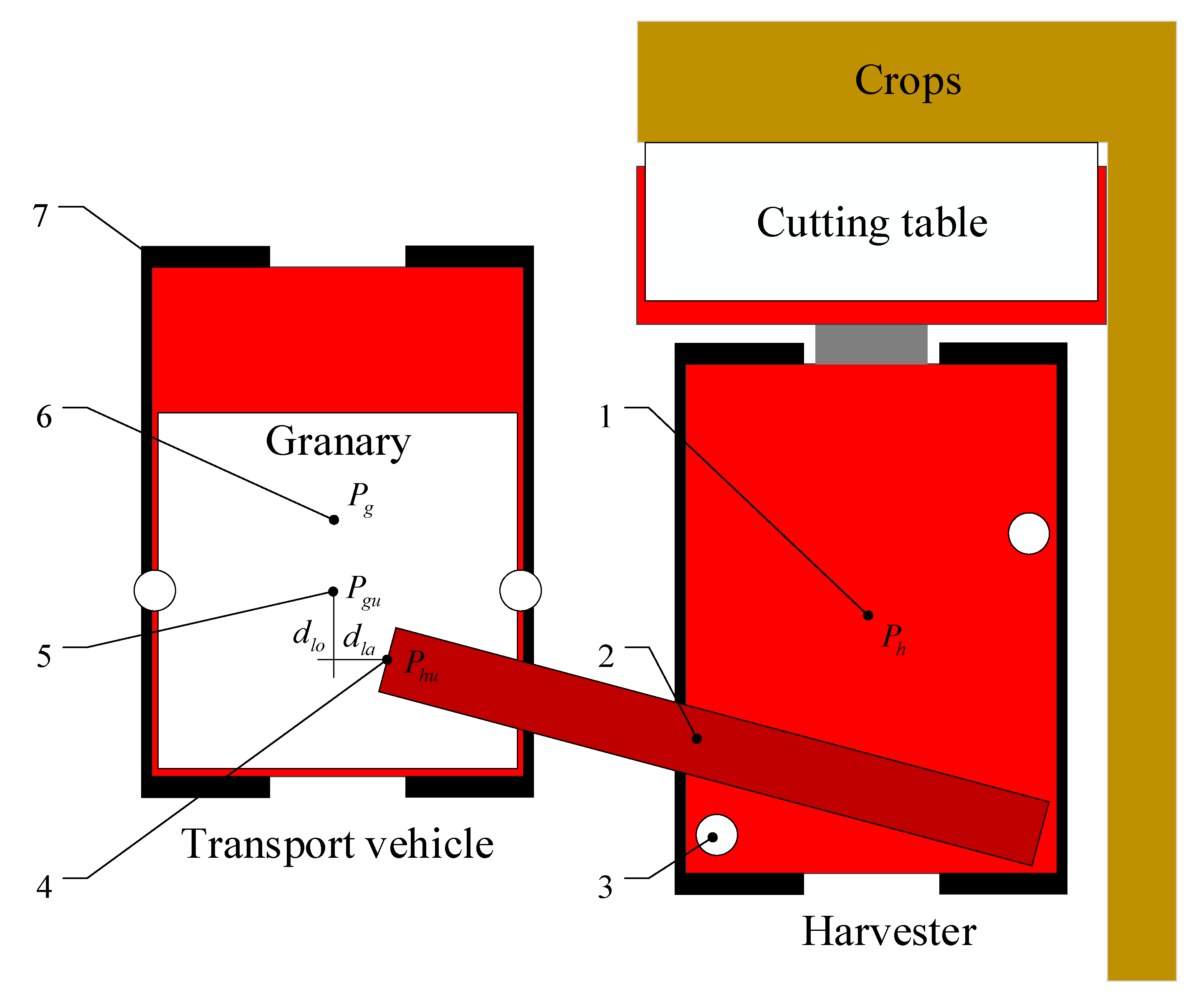
2.1. Communication Demand

The operation status of collaborative harvesting and precise grain unloading is shown in Figure 1, in which the harvester and the transport vehicle drive in parallel and the same direction. To enable the harvester to accurately unload grain into the transport vehicle during driving, it is necessary to control the relative positions of the harvester and transport vehicle at the same time to make sure the outlet position of the grain unloading cylinder (Phu) coincides with the grain unloading target point (Pgu). To do so, we decoupled the control in both the lateral and longitudinal directions: The relative lateral deviation (dla) between Phu and Pgu was adjusted and controlled by prior path planning and path tracking; its accuracy depends on the linear path tracking control effect of the two vehicles. The relative longitudinal deviation (dlo) is controlled by adjusting the speed of the transport vehicle.
When the harvester and transport vehicle are tracking straight paths, the standard deviation of the heading swing is less than 0.06°. Therefore, it can be assumed that during cooperative grain unloading, the heading of the harvester and transport vehicle is stable and consistent with the target heading. Thus, a simplified cooperative harvest grain unloading model can be obtained, as shown in Figure 2. According to the model, le = lhlg, P h P g = P h u P g u = dlo. Therefore, the relative longitudinal deviation (dlo) can be obtained by calculating the projection of Pg in the direction of the target heading (θ), and the positive and negative of cosβ can describe the relative front and rear positional relationship between the harvester and the transport vehicle. This paper stipulates that when the harvester is in the front and the transport vehicle is behind, the relative longitudinal deviation is positive; otherwise, it is negative. The specific calculation equation is:
d l o = p g p h cos β p g p h = y g y h + l e sin θ 2 + x g x h + l e cos θ 2 β = arctan y g y h + l e sin θ x g x h + l e cos θ θ l e = l g l h
To sum up, in the process of collaborative operation, effective information exchange between agricultural machinery is required; when the relative longitudinal deviation (dlo) is controlled in real time, the control effect depends not only on the quality of the control method but also on the update frequency, packet loss rate, and real-time interactive data.

2.2. Wireless Communication Design

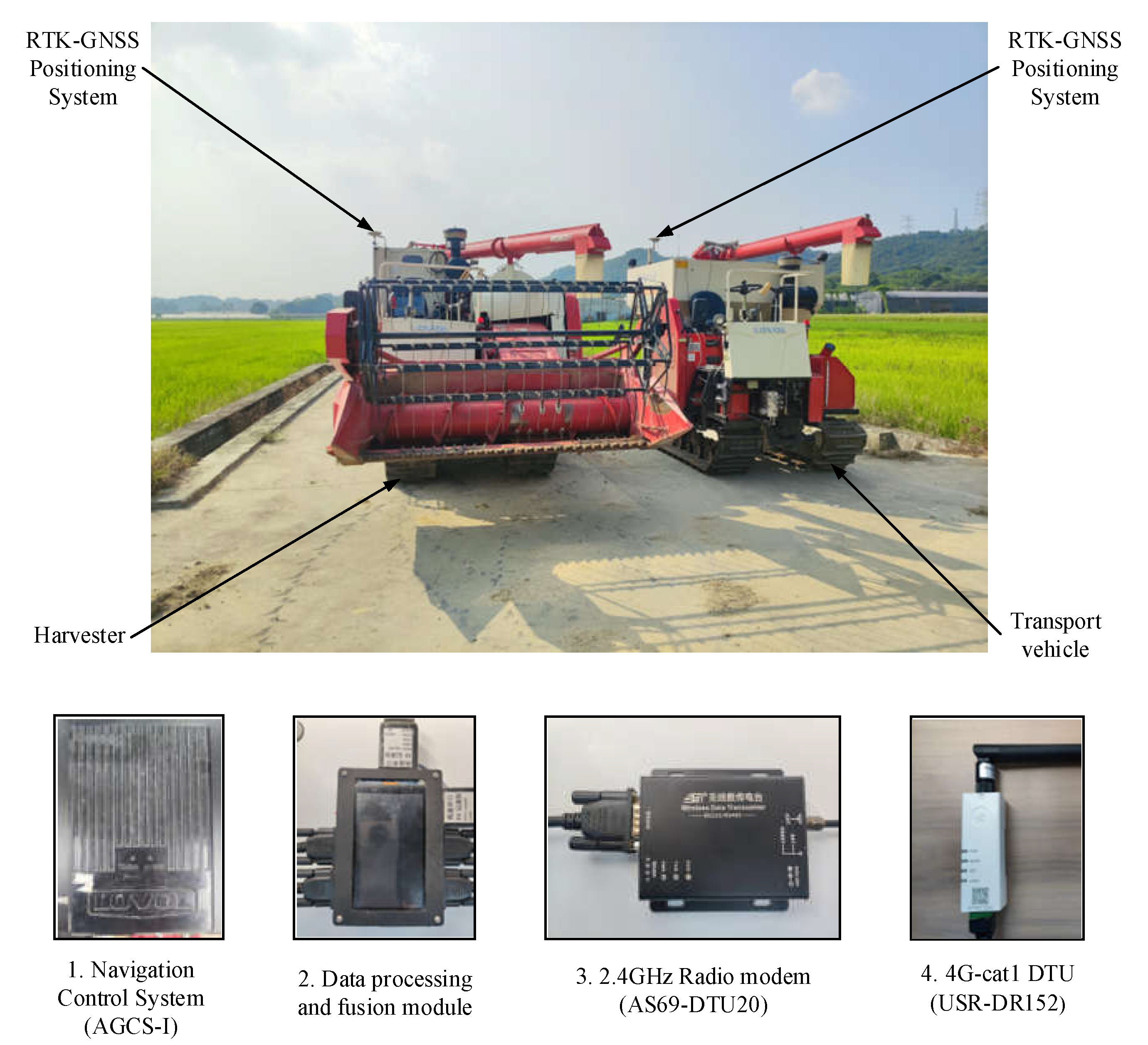
2.2.1. Data Transfer Unit (DTU)

Considering factors such as data transmission quality, effective communication distance, stability, cost, and convenience of use, as well as integrating actual needs such as scalability, networking, and real-time monitoring data, a 4G-cat1 data transmission terminal (USR-DR152) from the USR company (Jinan, Shandong, China) and a 2.4 GHz full-duplex wireless data transmission radio modem (AS69-DTU20) from the Ashining company (Chengdu, Sichuan, China)were used in this study. The STM32F407ZGT6 minimum system board from the ALIENTEK company (Guangzhou, China) was selected for data processing and the fusion module, which was connected to the navigation control system through an RS232 serial port to realize wireless communication during cooperative harvesting. The main technical parameters of the DTU and core board are shown in Table 2.
After actual testing, when the sending and receiving frequency of the 4G-cat1 data transmission terminal was 2 Hz and the 4G signal was good, the communication quality was good; in addition, it did not occupy too many network resources, communication nodes could continue to expand, and the communication data could be monitored in real time through a cloud platform. In the open environment of the farmland, the effective communication distance of the 2.4 GHz full-duplex wireless data transmission radio modem was 60 m; its sending and receiving frequency could reach 5 Hz, but the point-to-point mechanism made it inconvenient to expand communication nodes, and communication data could not be monitored in real time.

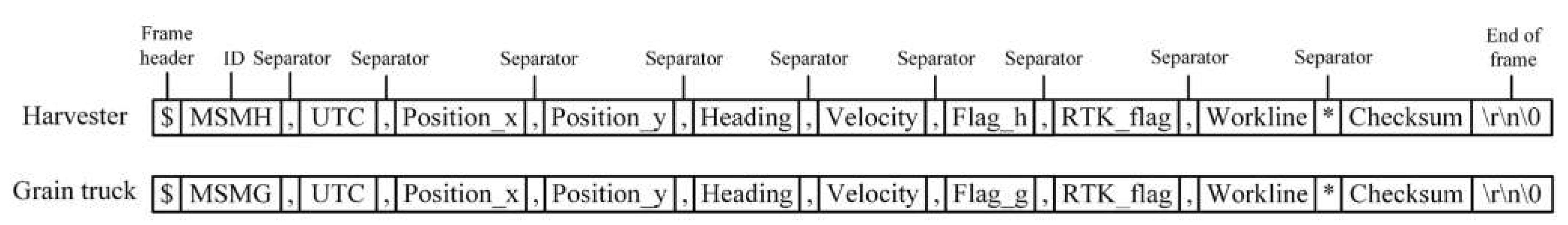
2.2.2. Communication Content and Protocol

The specific definition of the communication data between the harvester and transport vehicle is shown in Figure 3. The data frame starts with “$”and ends with a null character, “\0”, including plane coordinates X and Y in the navigation coordinate system; heading; speed; RTK flag; UTC (coordinated universal time); and the number of working lines. Each datum is separated by commas. A checksum was used for data verification to ensure the integrity and accuracy of the variable-length data.

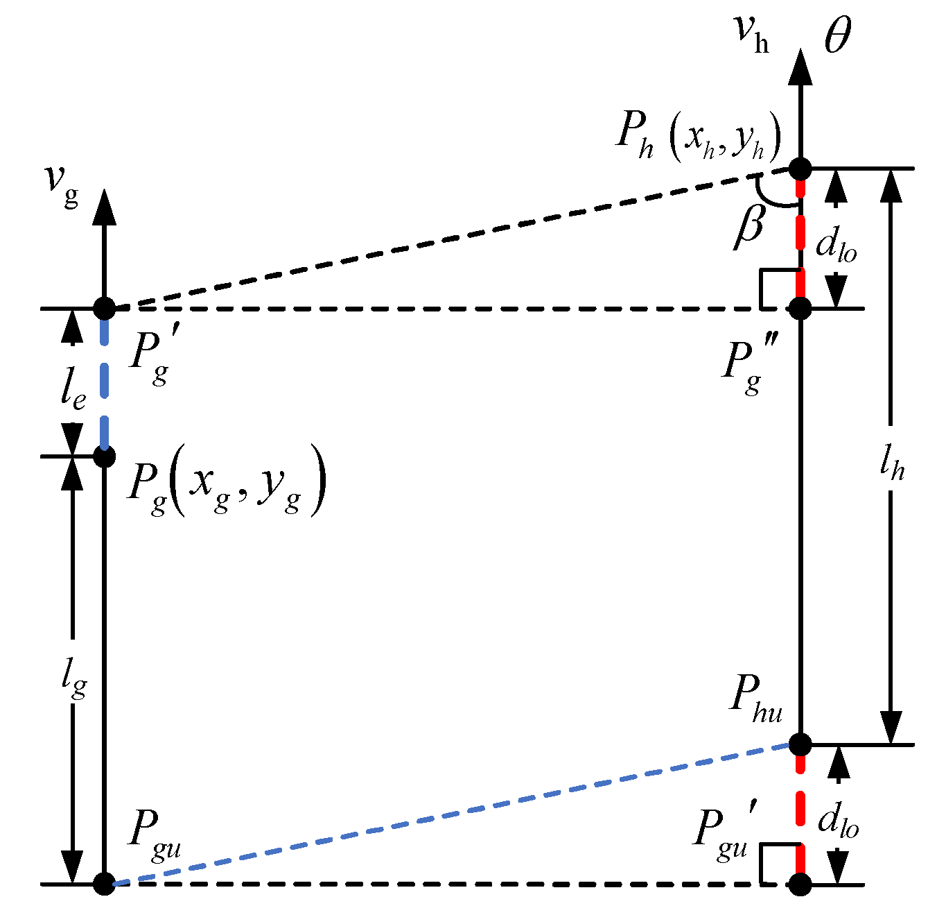
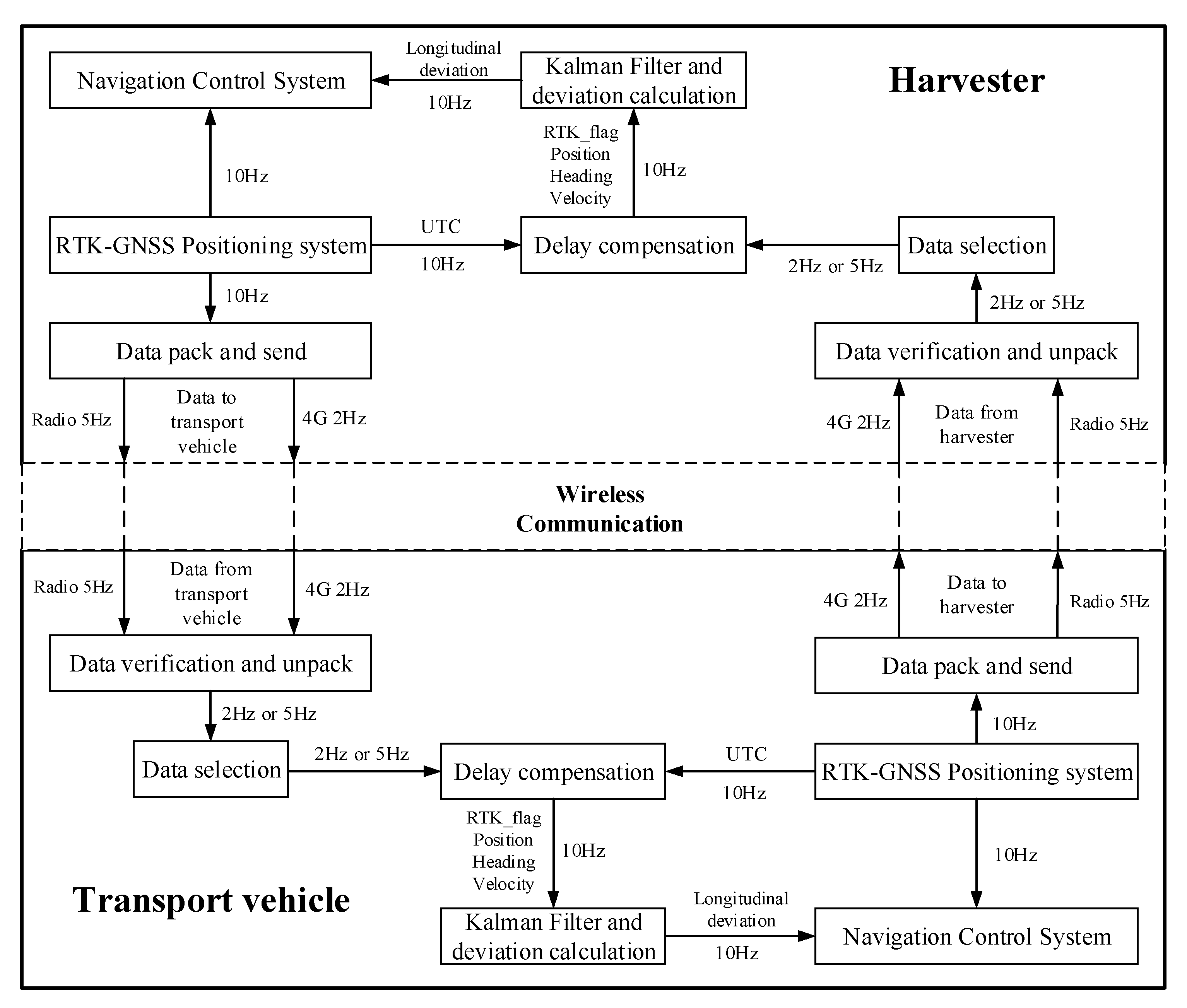
2.3. Kalman Filter Based on Dead-Reckoning and Communication Data after Delay Compensation (KFDCC)

Although the wireless data communication between a harvester and transport vehicle can transmit their respective location information, its update frequency is low. Furthermore, it is vulnerable to interference from the external environment, resulting in data packet loss, blockage, error, or delay. According to the principle of dead-reckoning, the future trajectory information can be estimated according to the current position, heading, speed, and other information, but the real error will accumulate with time. Therefore, this study used a Kalman filter to fuse low-quality and low-frequency wireless communication data and motion state prediction information to improve the update frequency, accuracy, and stability of inter-vehicle interactive data.

2.3.1. Basic Kalman Filter Design

Based on the principle of dead-reckoning, the motion state prediction equation of the harvester in a 2D plane navigation coordinate system was established as follows:
x h y h t = x h y h t 1 + v h x 0 0 v h y t 1 Δ t v h x v h y t 1 = cos θ h 0 0 sin θ h t 1 v h
In this formula, xh, yh are plane coordinates of harvester satellite positioning point Ph under the navigation coordinate system at time t; vhx, vhy are the velocity of harvester satellite positioning point Ph along the x and y axes in the navigation coordinate system at time t; ∆t is the time interval of dead-reckoning; θh is heading angle of the harvester at time t; vh is driving velocity of the harvester. ∆t is related to the update frequency of the interactive data between the harvester and the transport vehicle, while the control frequency of the navigation system and the refresh frequency of the satellite positioning information are 10 Hz, so the value of ∆t is 0.1 s. The motion state prediction equation of the transport vehicle in a 2D plane navigation coordinate system is the same as the harvester.
In practical applications, when controlling the relative longitudinal deviation (dlo) in real time, high-frequency and high-quality data interactions are required to provide timely and accurate feedback for the control, and this is reflected in the precise grain unloading process during the collaborative harvest. At this point, the harvester is in a state of straight-line driving at a constant speed. When entering a steady state and starting to unload grain, the transport vehicle will also be in a straight-line driving state at a constant speed. Therefore, it can be assumed that vhx and vhy are stable and slowly changing. The transport vehicle’s velocity, vgx and vgy, is also stable and slowly changes after it starts to unload grain.
According to Equation (2), the recursive equation describing the motion state of the harvester can be expressed as:
X t = A X t 1 + ω k a l
where X t = x h v h x y h v h y t T is a four-dimensional state space vector; ω k a l is the process excitation noise; and A = 1 Δ t 0 0 0 1 0 0 0 0 1 Δ t 0 0 0 1 is the state transition matrix.
The observed equation of the harvester’s position is:
Z t = H X t + v k a l
where Z t is the state observation vector; H = 1 0 0 0 0 1 0 0 0 0 1 0 0 0 0 1 is the observation matrix; and v k a l is the observation noise.
From Equations (3) and (4), the working process of the Kalman filter can be summarized as follows:
(1) Prior estimation of the system state at time t (Prediction process):
X ^ t = A X ^ t 1 +
where X ^ t is the estimated value obtained from the state transition equation at time t (a priori estimate) and X ^ t 1 + is the optimal estimate of the state of harvester at time t−1 (a posteriori estimate).
(2) The priori estimation of the covariance matrix, P ^ t , at time t (Prediction process):
P ^ t = A P ^ t 1 + A T + Q
where P ^ t 1 + is the posterior estimate of the covariance matrix at time t−1 and Q is the four-dimensional process noise covariance matrix.
(3) Calculation of Kalman gain at time t (Update process):
K t = P ^ t H T H P ^ t H T + R 1
where R is the four-dimensional observation noise covariance matrix.
(4) Calculation of the posterior estimation of the system state at time t (Update process):
X ^ t + = X ^ t + K t Z t H X ^ t
where X ^ t + is the optimal estimate of the state of the harvester at time t (posterior estimate).
(5) Posterior estimate of the covariance matrix, P ^ t + , at time t (Update process):
P ^ t + = I K t H P ^ t
where I is the unit vector.
According to the mathematical derivation process of the Kalman filter, the ratio of process noise covariance matrix Q and observation noise covariance matrix R will affect the output of the filter and the value of the relative longitudinal deviation (dlo) between the harvester and transport vehicle [23]. In this study, two parameters were set according to the test setting results:
Q = 0.03 0 0 0 0 0.01 0 0 0 0 0.03 0 0 0 0 0.01 R = 0.3 0 0 0 0 0.1 0 0 0 0 0.3 0 0 0 0 0.1

2.3.2. Delay Compensation of the Observation

Wireless communication has a larger delay than wired communication. To reduce the impact of communication delay on real-time control, it is necessary to compensate for the interactive data (observation vector Zt of the Kalman filter) of the harvester and transport vehicle in real time. The specific calculation formula is as follows:
x v x y v y C = x v x y v y + cos θ 0 sin θ 0 v T d T d = T c T l
θ, v, and Tc are heading angle (°), velocity (m/s), and UTC (Universal Time Coordinated) in the interactive data frame, respectively; Tl is UTC (Universal Time Coordinated) of the local agricultural machinery, and Td is the communication delay time (s).

2.3.3. Information Processing Method

According to the requirements of data interaction in collaborative harvesting, an information processing method was designed based on Section 2.2.1 and Section 2.2.2; the overall structure is shown in Figure 4. The wireless communication and data interaction between the harvester and transport vehicle were carried out through a 4G data transmission terminal and a data transmission radio modem, and their data transmission and reception frequencies were 2 and 5 Hz, respectively. The relative longitudinal deviation (dlo) between the harvester and transport vehicle was obtained after prediction and data fusion using the Kalman filter, and the data update frequency was increased to 10 Hz.
The Kalman filter observations came from the 4G data transmission terminal and wireless data transmission radio modem, and the two wireless communication modes complemented each other. When the 4G link and radio link were smooth, according to the characteristics of the two communication modes, the switch was carried out based on the distance between the harvester and the transport vehicle: The wireless data transmission station was selected for a short distance (<35 m), and the 4G data transmission terminal was selected for long distance (≥35 m). Before each filter iteration, the observation value needed to be compensated for the delay. The position is the plane coordinate of the satellite positioning point in the navigation coordinate system, which went through Gaussian projection, coordinate transformation, and delay compensation. The original latitude and longitude information of the position, UTC, heading, velocity, and RTK_flag all came from real-time GPGGA messages sent by RTK-GNSS boards in the navigation system of the harvester and transport vehicle. The fixed solution (RTK_flag = 4) was the normal state of satellite positioning, and the information under the other solution categories was not credible, so it was selected as a sign of Kalman filter initialization and normal operation. The operation stopped when the communication link between the harvester and transport vehicle was interrupted for more than 6 s.

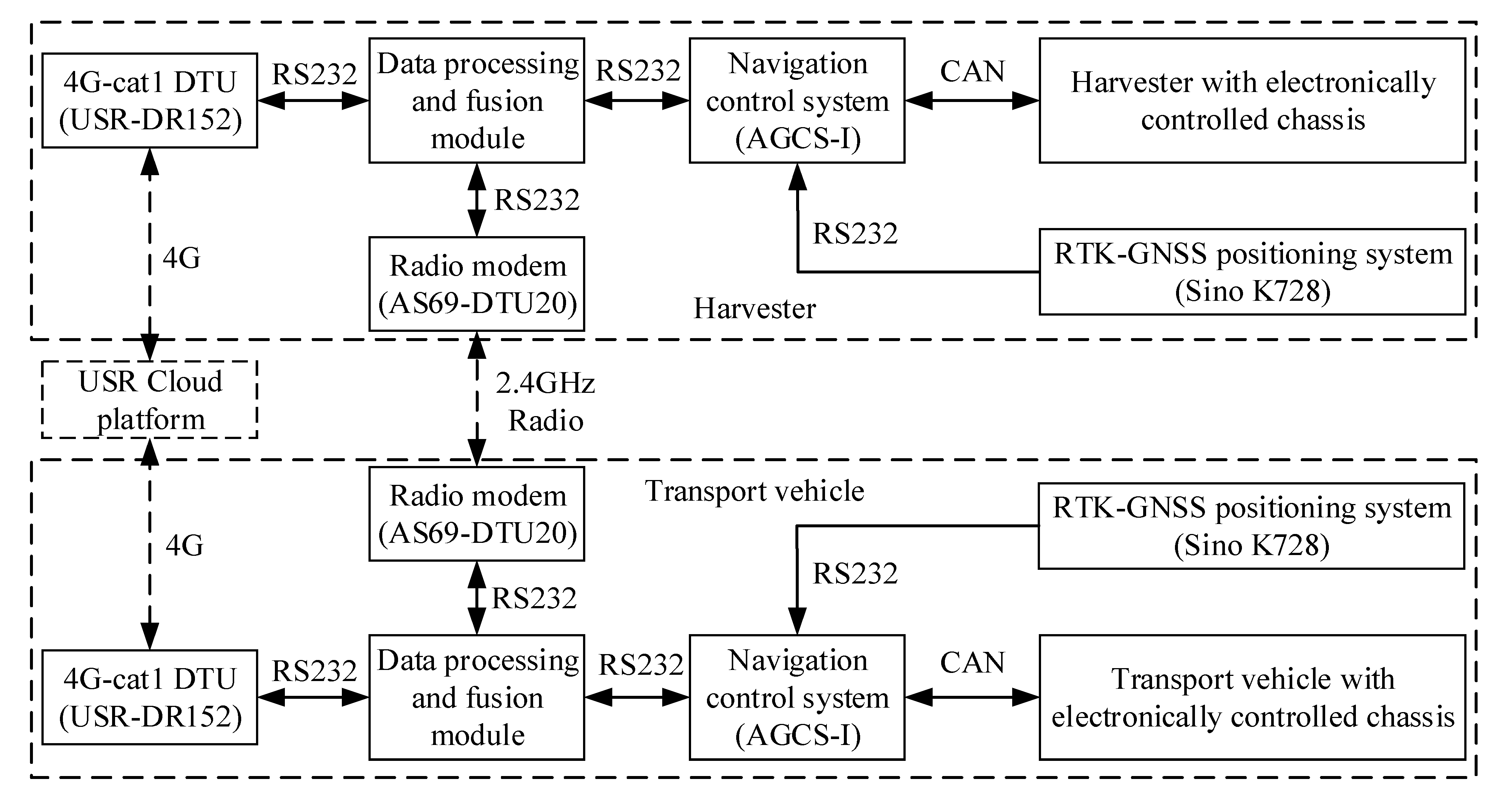
2.4. Overall Design of the Test System

To verify the effectiveness and accuracy of the data processing and fusion algorithm, a cooperative harvest and inter-vehicle communication test system was built using a harvester and transport vehicle. The harvester (RG60V4G-036 from WEICHAI LOVOL Heavy Industry) and the transport vehicle (RG60V4G-037 from WEICHAI LOVOL Heavy Industry) both adopted electrically controlled chassis that could electronically control the hydraulic steering, continuously variable transmission, engine, cutting table, threshing drum, grain unloading cylinder, and other actuators. The main parameters are shown in Table 3. The navigation control system was the AGCS-I, which communicated with the chassis electronic control unit of the harvester or transport vehicle through the CAN bus. The software was developed by Metrowerks Code Warrior for ARM Developer Suite v1.2. The positioning module adopted the K728 dual antenna RTK-GNSS board card of the Shanghai Sino company. The frequency for obtaining the positioning information was 10 Hz, and the horizontal positioning accuracy was ±(10 + D × 10 − 6) mm, where D is the distance from the base station to the mobile station (km). The overall system structure and test platform are shown in Figure 5 and Figure 6.

3. Results and Discussion

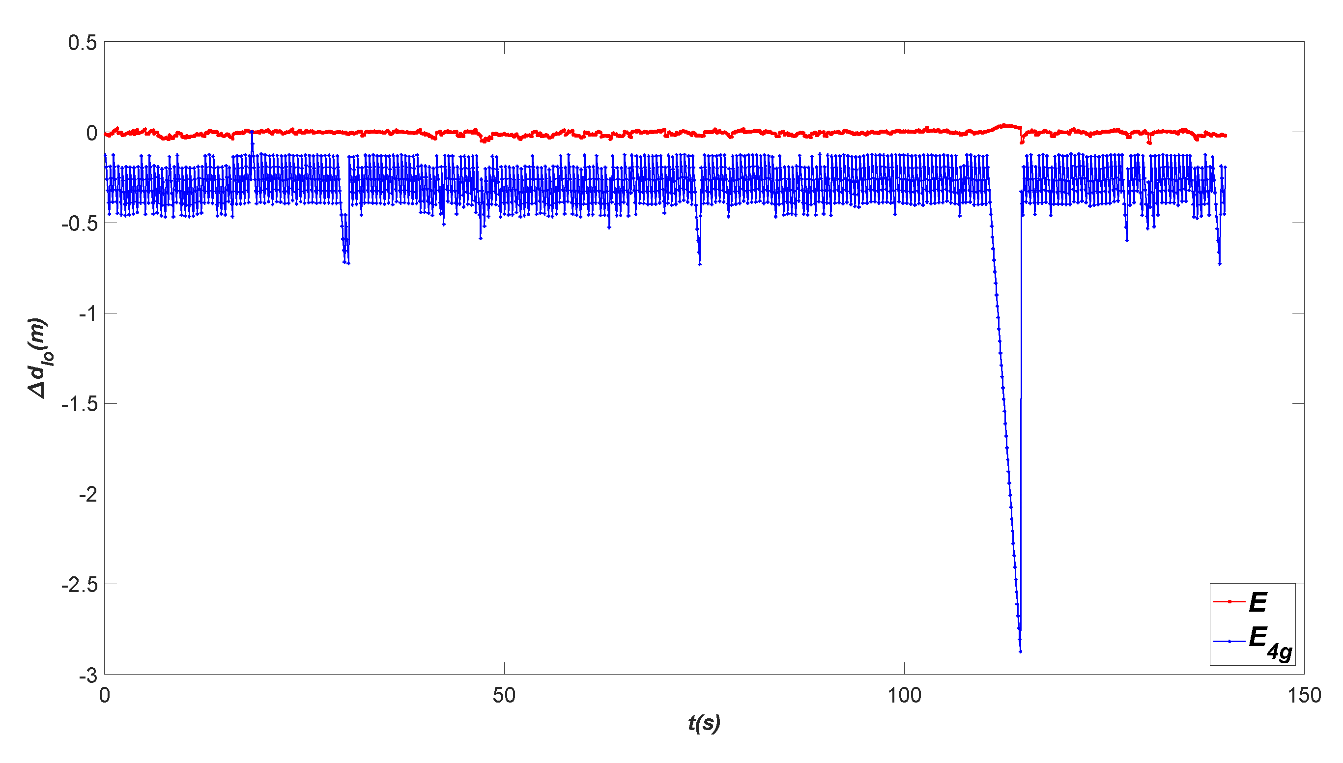
3.1. Algorithm Accuracy Evaluation and Validation

In order to verify the effectiveness and accuracy of the KFDCC algorithm in Section 2, experiments were conducted on the cement pavement of the Zengcheng Teaching and Research Base, South China Agricultural University. The test scenario is shown in Figure 6. The straight path of the cooperative harvest system was planned with the harvester on the right and the transport vehicle on the left, and the path spacing was 2.5 m. The hardware for the inter-vehicle communication, data processing, and the acquisition and calculation of relative longitudinal deviation (dlo) all adopted the method described in Section 2; a path-tracking method based on a preview-tracking model was used to control the relative lateral deviation (dla) of the harvester and transport vehicle. The speed of the harvester was set to 0.7 m/s according to actual operation requirements. An incremental PID method was used to control the relative longitudinal deviation (dlo) of the harvester by adjusting the speed of the transport vehicle. Two groups of tests were set up with three replicates in each group. The first group used a wireless data transmission radio modem (AS69-DTU20) for inter-vehicle communication, and the second group used a 4G data transmission terminal (USR-DR152) for inter-vehicle communication to test the effectiveness and accuracy of the KFDCC algorithm in both wireless communication modes. During the test, the GNSS data of the harvester and transport vehicle and the input and output data of the KFDCC algorithm were recorded at a 10 Hz frequency.
According to the local GNSS data of the harvester and transport vehicle, the UTC stamp was aligned, and the actual relative longitudinal deviation of the two vehicles was calculated by referring to Equation (1), denoted as dre, which was used as the comparative metric for the algorithm accuracy test. The relative longitudinal deviation obtained without the KFDCC algorithm fusion was calculated by referring to Equation (1), based on the position information of the opposite vehicle transmitted through the wireless communication and GNSS data of the local vehicle at the then-current moment. This distance was the input of the KFDCC algorithm, and it can be denoted as dra or d4g according to the adopted communication mode. The relative longitudinal deviation output by the KFDCC algorithm is denoted as d. The build accuracy evaluation index is as follows:
E = d d r e E r a = d r a d r e E 4 g = d 4 g d r e
If E is an indicator to check the accuracy of the KFDCC algorithm, then Era or E4g can be compared with E to reflect the effectiveness and advantages of the KFDCC algorithm. Owing to the relative longitudinal deviation (d), the output of the KFDCC algorithm from the transport vehicle acted as the feedback value in the actual control; the two-vehicle KFDCC algorithm was consistent, and the input and output data of the KFDCC algorithm from the transport vehicle were used for numerical analysis. Figure 7 shows schematic diagrams of real-time E and E4g when the harvester and transport vehicle entered a longitudinal alignment steady state in the case of the wireless data transmission 4G communication mode.
The results of the three repeated tests from the two groups are shown in Table 4. Test No.3 of the second group is the data in Figure 7. When the wireless data transmission radio modem was used for inter-vehicle communication, the maximum absolute error of E was 0.03783 m, and the mean square error was 0.00392 m; compared with Era, the mean square error was reduced by 0.03097 m (88.76%). When the 4G-cat1 data transmission terminal was used for inter-vehicle communication, the maximum absolute error of E was 0.07381 m, and the mean square error was 0.01317 m; compared with E4g, the mean square error was reduced by 0.12693 m (90.60%). From different test results, the real-time accuracy and effectiveness of the KFDCC algorithm under two different communication modes can be seen intuitively. The KFDCC algorithm effectively solved the packet loss and delay problems of wireless communication and had great advantages compared with using wireless communication data directly. According to the data in Figure 8, inter-vehicle communication was interrupted within 4.5 s, from 89.3 to 93.8 s. Though d4g quickly deviated from the true value dre, the output value d, of the KFDCC algorithm could still be maintained near dre; the KFDCC method had short-time breakpoint endurance capabilities. Overall, the proposed KFDCC algorithm had a good effect, and it can adapt to two different wireless communication modes: a wireless data transmission radio modem and a 4G-cat1 data transmission terminal.

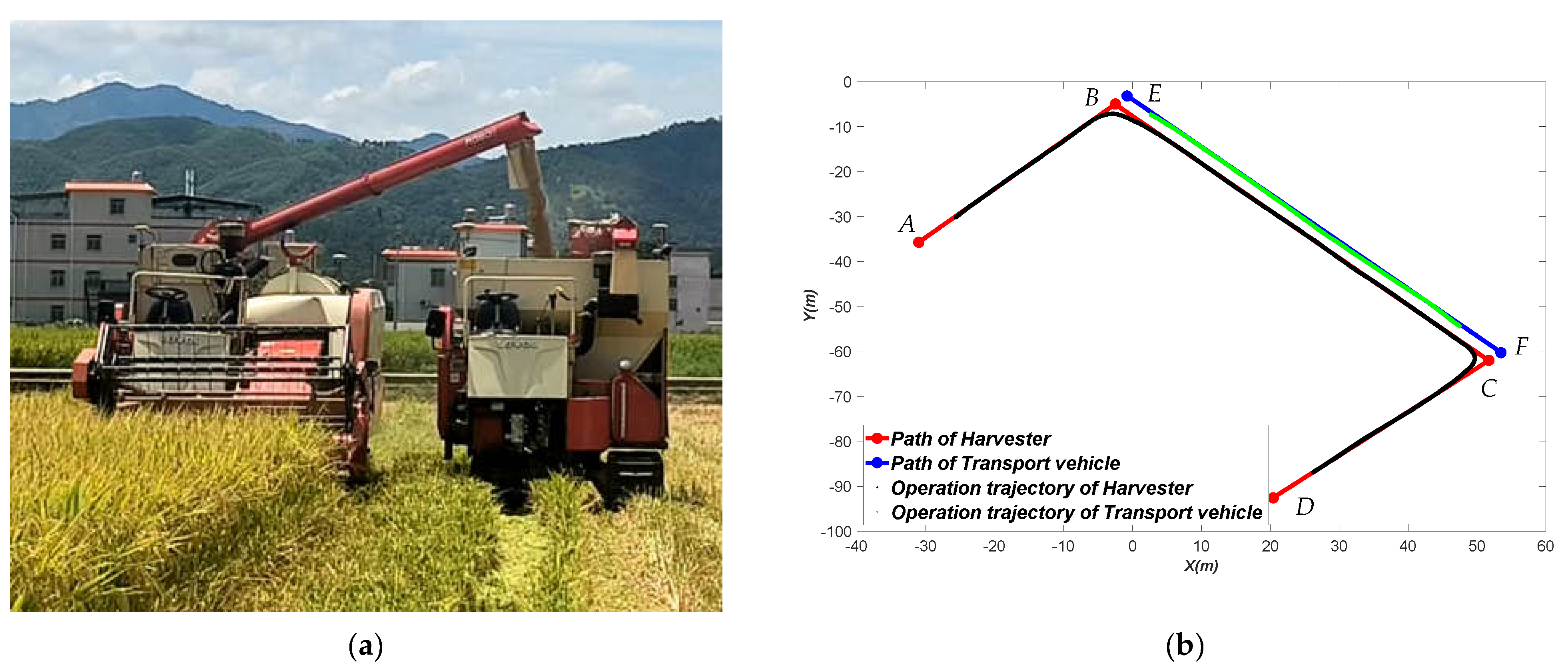
3.2. Field Harvesting Application

To verify the effect of the inter-vehicle communication method in an actual field harvest, a cooperative harvesting and unloading experiment was conducted at Wanlu Smart Farm, Dongyuan, Heyuan, Guangdong Province. The test scene is shown in Figure 9a.
The path plan for a single, precise grain-receiving operation for cooperative harvesting and unloading is shown in Figure 8b. ABCD is the path of the harvester, and EF is the path of the transport vehicle; the BC section and EF section are collaborative grain-unloading paths, and the path spacing is 2.5 m. The path-tracking control method, speed setting, and relative longitudinal deviation (dlo) control method of the harvester and transport vehicle were consistent with Section 3.1. The switching strategy of two different wireless communication modes—a wireless data transmission radio modem and a 4G-cat1 data transmission terminal—is described in Section 2.3.3. The actual operation process is as follows: The harvester starts at point A and the transport vehicle waits at point E; when the harvester reaches point B, the transport vehicle starts; when the harvester finishes turning, the transport vehicle starts to decelerate and aligns with harvester longitudinally; after alignment is complete, the harvester begins to unload grain, and the transport vehicle continues to follow; when the harvester reaches point C and starts to turn, it stops unloading grain, and the transport vehicle stops at the same time. The operation trajectories of the harvester and transport vehicle are shown in Figure 8b. During the experiment, the data storage and recording were consistent with the description in Section 3.2.
The build accuracy evaluation index is as follows:
E = d d r e E F L D = d F L D d r e
dFLD was consistent with the acquisition methods of dra and d4g in Section 3.1; d and dre were the same as described in Section 3.1. Figure 9 shows schematic diagrams of real-time d, dre, and dFLD and E, and Era during the longitudinal alignment process of the harvester and transport vehicle. The experiment results are shown in Table 5; the maximum absolute error of E was 0.04863 m, and the mean square error was 0.00542 m; compared with EFLD, the mean square error was reduced by 0.03052 m (84.92%). The inter-vehicle communication and data processing method designed in this paper can adapt to actual field operations and provide accurate data support for the subsequent control link.

4. Conclusions and Prospects

This paper designed a wireless communication protocol by analyzing the actual communication needs of the harvester and the transport vehicle in the process of real-time vertical alignment and precise grain unloading. Two different wireless communication modes, radio and 4G, were used to realize the inter-machine communication. Meanwhile, a KFDCC method was proposed to process, compensate and correct the inter-machine communication data in real time, and the experimental verification was completed. In the test of cement pavement, two different communication modes of radio (data update frequency was 5 Hz) and 4G (data update frequency was 2 Hz) were tested and verified, respectively. Among them, the KFDCC method could stably update the relative longitudinal deviation dlo between the harvesters and the transport vehicles at a frequency of 10 Hz. Compared with the comparative metric dre, the Maximum Absolute Error (MAE) were 0.03783 and 0.07381 m, and the Mean Square Errors (MSE) were 0.00392 and 0.01317 m, respectively. Compared with the method without KFDCC, the Maximum Absolute Error (MAE) were reduced by 82.29% and 93.28%, and the Mean Square Errors (MSE) was reduced by 88.76% and 90.60%, respectively; the KFDCC method can effectively solve the problems of packet loss and delay in wireless communication, and has a certain breakpoint endurance in a short time. The experiment showed that KFDCC method has good precision and the effect of data prediction and fusion. In addition, the two wireless communication modes can also complement each other as design redundancy for inter-machine communication between harvesters and transport vehicles.
In the field experiment of actual harvesting operation, the Maximum Absolute Error (MAE) of the relative longitudinal deviation dlo between the harvesters and the transport vehicles was 0.04863 m and the Maximum Absolute Error (MAE) was 0.00542 m compared with the comparative metric dre. Furthermore, its update frequency could always be synchronized with the control frequency which was effectively served as the real-time feedback of longitudinal control. Therefore, the inter-machine communication method designed in this paper can adapt to the field operation scenario, and ensure the real-time longitudinal alignment and accurate grain unloading between harvesters and transport vehicles.
Overall, the inter-vehicle communication mode and data processing method designed in this paper had a good effect, which can provide data support for subsequent control links and ensure the whole process of independent harvesting operations. The KFDCC method also provided algorithmic support for the multiple wireless communication modes used in inter-vehicle communication as design redundancies. At this stage, harvesters work at a constant speed during operation, so this paper does not introduce acceleration during dead-reckoning. In the future, with the improvement of harvester sensors and the progress of autonomous operation technology, the operation speed of harvesters will be dynamically adjusted in real time according to the feeding quantity. Therefore, introducing acceleration during dead-reckoning and improving the adaptability of the KFDCC algorithm to variable speed operations will likely be one of the directions of future research.

Author Contributions

F.D.: methodology, software, validation, formal analysis, investigation, resources, data curation, writing—original draft preparation, writing—review and editing, visualization. Z.Z.: conceptualization, validation, supervision, funding acquisition, resources, writing—review and editing. X.L.: conceptualization, resources, validation, supervision, project administration. M.W.: formal analysis, investigation, data curation. H.L.: software, investigation. M.P.: investigation. L.H.: investigation. W.Z.: conceptualization, software, validation, supervision, resources, writing—review and editing. All authors have read and agreed to the published version of the manuscript.

Funding

This research was funded by the National Natural Science Foundation of China (nos. 32071914), the Modern Agricultural Industry Technology System of China (CARS-170405), and Basic and Applied Research Fund of Guangdong Province of China (nos. 2019A1515111152).

Institutional Review Board Statement

Not applicable.

Data Availability Statement

The data that support the findings of this study are available on request from the corresponding author.

Acknowledgments

The authors thank Xiwen Luo, Zhigang Zhang and Wenyu Zhang for their financial support, guidance and assistance. The authors also gratefully acknowledge the editors and anonymous reviewers for their constructive comments on our manuscript.

Conflicts of Interest

The authors declare no conflict of interest.

References

  1. Qi, Y.J.; Tang, C. Effect of labor migration on cultivated land planting structure in rural China. Trans. Chin. Soc. Agric. Eng. 2017, 33, 233–240. [Google Scholar]
  2. Li, D.L.; Li, Z. System Analysis and Development Prospect of Unmanned Farming. Trans. Chin. Soc. Agric. Mach. 2020, 51, 1–12. [Google Scholar]
  3. Luo, X.W.; Liao, J.; Hu, L.; Zhou, Z.Y.; Zhang, Z.G.; Zang, Y.; Wang, P.; He, J. Research progress of intelligent agricultural machinery and practice of unmanned farm in China. J. South China Agric. Univ. 2021, 42, 8–17. [Google Scholar]
  4. Peng, X.R. Research on Multi-Vehicle Cooperation based on Mini Intelligent Vehicles. Master’s Thesis, Shanghai Jiao Tong University, Shanghai, China, 2010. [Google Scholar]
  5. Alshabtat, A.I.; Dong, L. Low Latency Routing Algorithm for Unmanned Aerial Vehicles Ad-Hoc Networks. Int. J. Electr. Comput. Eng. 2011, 5, 989–995. [Google Scholar]
  6. Shen, Z.Y.; Zheng, Q.W.; Wang, C. Multi-smart car control system based on wireless communication network. J. Southeast Univ. (Nat. Sci. Ed.) 2013, 43, 18–21. [Google Scholar]
  7. Zhang, K.B.W.; Deng, C.; Ou, Y.L. Design of Multi-vehicle Following Control System based on Arduino. Int. J. Comput. Appl. 2016, 140, 5–8. [Google Scholar] [CrossRef]
  8. Rosati, S.; Kruzelecki, K.; Heitz, G.; Floreano, D.; Rimoldi, B. Dynamic Routing for Flying Ad Hoc Networks. IEEE Trans. Veh. Technol. 2016, 65, 1690–1700. [Google Scholar] [CrossRef] [Green Version]
  9. Yajima, H.; Takami, K. Inter-Vehicle Communication Protocol Design for a Yielding Decision at an Unsignalized Intersection and Evaluation of the Protocol Using Radio Control Cars Equipped with Raspberry Pi. Computers 2019, 8, 16. [Google Scholar] [CrossRef] [Green Version]
  10. Nakazawa, T.; Tang, S.; Obana, S. CCN-Based Inter-Vehicle Communication for Efficient Collection of Road and Traffic Information. Electronics 2020, 9, 112. [Google Scholar] [CrossRef] [Green Version]
  11. Zhu, Z.; Takeda, J.; Xie, B. Tractor platooning system on sloping terrain at low speed. Trans. ASABE 2009, 52, 1385–1393. [Google Scholar] [CrossRef]
  12. Zhang, X.; Geimer, M.; Noack, P.O.; Grandl, L. A semi-autonomous tractor in an intelligent master–slave vehicle system. Intell. Serv. Robot. 2010, 3, 263–269. [Google Scholar] [CrossRef]
  13. Wang, Z.Q. Design and realization on autonomous following control system of agricultural vehicles. Master’s Thesis, Nanjing Agricultural University, Nanjing, China, 2014. [Google Scholar]
  14. Noguchi, N.; Will, J.; Reid, J.; Zhang, Q. Development of a master–slave robot system for farm operations. Comput. Electron. Agric. 2004, 44, 1–19. [Google Scholar] [CrossRef]
  15. Zhang, C.; Noguchi, N.; Yang, L. Leader–follower system using two robot tractors to improve work efficiency. Comput. Electron. Agric. 2016, 121, 269–281. [Google Scholar] [CrossRef]
  16. Bai, X.P.; Wang, Z.; Hu, J.T.; Gao, L.; Xiong, F. Harvester Group Corporative Navigation Method Based on Leader-Follower Structure. Trans. Chin. Soc. Agric. Mach. 2017, 48, 14–21. [Google Scholar]
  17. Li, S.; Cao, R.; Wei, S.; Ji, Y.; Zhang, M.; Li, H. Development of Multi-vehicle Cooperative Navigation Communication System Based on TD-LTE. Trans. Chin. Soc. Agric. Mach. 2017, 48, 45–51+65. [Google Scholar]
  18. Li, S.; Xu, H.; Ji, Y.; Cao, R.; Zhang, M.; Li, H. Development of a following agricultural machinery automatic navigation system. Comput. Electron. Agric. 2019, 158, 335–344. [Google Scholar] [CrossRef]
  19. Zhang, W.; Zhang, Z.; Luo, X.; He, J.; Hu, L.; Yue, B. Position-velocity coupling control method and experiments for longitudinal relative position of harvester and transport vehicle. Trans. Chin. Soc. Agric. Eng. 2021, 37, 1–11. [Google Scholar]
  20. Chen, J.; Fu, S.; Guan, Z.; Zhu, F.; Zhu, L.; Xia, H.; Xing, L. Communication method of combine harvester group based on Lora Technology. Trans. Chin. Soc. Agric. Eng. 2022, 38, 81–89. [Google Scholar]
  21. Li, D.L.; Yang, H. State-of-the-art Review for Internet of Things in Agriculture. Trans. Chin. Soc. Agric. Mach. 2018, 49, 1–20. [Google Scholar]
  22. Zhang, M.; Ji, Y.H.; Li, S.C.; Cao, R.Y.; Xu, H.Z.; Zhang, Z.Q. lResearch Progress of Agricultural Machinery Navigation Technology. Trans. Chin. Soc. Agric. Mach. 2020, 51, 1–18. [Google Scholar]
  23. Akhlaghi, S.; Zhou, N.; Huang, Z. In Adaptive Adjustment of Noise Covariance in Kalman Filter for Dynamic State Estimation. In Proceedings of the 2017 IEEE Power & Energy Society General Meeting, Chicago, IL, USA, 16–20 July 2017; pp. 1–5. [Google Scholar]
Figure 1. Schematic diagram of a collaborative harvest unloading operation. 1. Harvester positioning point. 2. Grain unloading barrel. 3. GNSS receiving antenna. 4. Grain unloading port. 5. Grain unloading target point. 6. Transport vehicle positioning point. 7. Pedrail. Note: Ph is the satellite positioning point of the harvester; Pg is the satellite positioning point of the transport vehicle; Phu is the grain unloading port point of the harvester; Pgu is the target point of the grain unloading; dla is the relative lateral deviation between Phu and Pgu; dlo is the relative longitudinal deviation between Phu and Pgu.
Agriculture 12 02052 g001
Figure 2. Schematic diagram of a simplified collaborative unloading operation. Note: (xh,yh) is the Ph point coordinate, m; (xg,yg) is the Pg point coordinate, m; vh is the driving velocity of the harvester, m/s; vg is the driving velocity of the transport vehicle, m/s; θ is the target heading angle of the harvester and transport vehicle; lh is the distance from the projection point of the grain unloading port point, Phu, in the direction of θ with the satellite positioning point of the harvester, Ph; lg is the distance from the target point of grain unloading, Pgu, to the satellite positioning point of the transport vehicle, Pg; le is the difference between lg and lh; P g is the point at an le distance from point Pg in the direction of θ; P g is the projection of point P g in the direction of θ; P g u is the projection of point Pgu in the direction of θ; β is the angle between P h P g and θ.
Agriculture 12 02052 g002
Figure 3. Definition of wireless communication data frame.
Agriculture 12 02052 g003
Figure 4. Schematic diagram of the overall structure of information processing.
Agriculture 12 02052 g004
Figure 5. Structure diagram of collaborative harvest system.
Agriculture 12 02052 g005
Figure 6. Inter-vehicle communication test scene of collaborative harvest system.
Agriculture 12 02052 g006
Figure 7. Schematic diagram of real-time E and E4g.
Agriculture 12 02052 g007
Figure 8. (a) Field work scene of collaborative harvesting and unloading; (b) the path plan and operation trajectories of harvester and transport vehicle.
Agriculture 12 02052 g008
Figure 9. Field harvesting application: (a) Schematic diagram of real-time d, dre, and dFLD; (b) schematic diagram of real-time E and EFLD.
Agriculture 12 02052 g009
Table 1. Summary of wireless communication methods.
ItemsDistanceCharacteristics
Short-rangeZigBee30–50 mLow speed, node, low power consumption
Wi-Fi<100 mHigh speed, common communication quality
Bluetooth<10 mShort distance, slow reconnection
Ultra-Wide-band<10 mShort distance, high cost
Long-distanceRadio modem1–25 kmPoint to point, limited channel, real-time
performance
Cellular mobile communication
(2G/3G/4G/5G)
36 kmHigh speed, great potential, easy to use, wide range, operator dependent
LoRa15 kmLow speed, low power consumption, relay station
NB-IoT20 kmInadequate adaptability, operator dependent
Table 2. Main parameters of DTU and Core board.
ItemsParametersDescriptions
4G-cat1 DTU (USR-DR152)Power Supply5 V~16 V DC
NetworkChina Mobile/China Unicom/China Telecom
LTE Cat-1
SpecificationsTDD-LTE, FDD-LTE
Speed10 Mbps downstream,5 Mbps upstream
UARTRS232
Baud1200~230,400 bps
2.4 GHz
Radio modem
(AS69-DTU20)
Power Supply8 V~28 V DC
Frequency2.405~2.525 GHz
UARTRS232/RS485
Baud1200 bps~115,200 bps
FeatureFull Duplex
ALIENTEK STM32F407ZGT6 Minimal System BoardCPUSTM32F407ZGT6, LQFP144
FLASH1024 K
SRAM192 K + 8 M Bit(external expansion)
Serial Port4 *USART, 2 *UART
Table 3. Main structural parameters of the harvester and transport vehicle.
ItemsParametersValues
Harvester
(LOVOL RG60V4G-036)
Overall dimensions/(mm × mm × mm)5930 × 2500 × 2945
Overall weight/kg3900
Matching power/kW88
Cutting width/mm2100
Feed quantity/(kg/s)6
Granary volume/m31.3
Transport vehicle
(LOVOL RG60V4G-037)
Overall dimensions/(mm × mm × mm)3086 × 2080 × 2738
Overall weight/kg2500
Matching power/kW88
Granary volume/m32.5
Forward speed range/(km/h)1.08–7.2
Table 4. Test results of algorithm accuracy evaluation.
Wireless
Communication
Test No.MAE 1 of E (m)MSE 2 of E (m)PLR 3 of KFDCC OutputMAE of Era or E4g (m)MSE of Era or E4g (m)PLR of Wireless Communication
Radio modem (AS69-DTU20)10.038810.003850%0.391310.038962.79%
20.038820.003870%0.148470.033140.31%
30.039270.004510%0.176630.032830.53%
40.036580.004070%0.163610.033850.41%
50.035690.003310%0.186740.035680.57%
AVG 40.037830.003920%0.213350.034890.92%
4G-cat1 DTU (USR-DR152)10.069220.013480%0.588960.107053.33%
20.070020.014190%0.849270.118384.01%
30.072380.012930%2.873760.272634.33%
40.061990.008820%0.587190.095502.61%
50.095450.016430%0.588960.106903.06%
AVG0.073810.013170%1.097630.140103.47%
1 Maximum Absolute Error. 2 Mean Square Error. 3 Packet Loss Rate. 4 The Average Value.
Table 5. Test results of field harvesting application.
TestTest No.MAE 1 of E (m)MSE 2 of E (m)PLR 3 of KFDCC OutputMAE of EFLD (m)MSE of EFLD (m)PLR of Wireless Communication
cooperative harvesting and unloading10.041540.005470%0.478170.041512.39%
20.049760.005940%0.368930.032871.06%
30.054590.004850%0.292330.033430.93%
AVG 40.048630.005420%0.379810.035941.46%
1 Maximum Absolute Error. 2 Mean Square Error. 3 Packet Loss Rate. 4 The Average Value.
Publisher’s Note: MDPI stays neutral with regard to jurisdictional claims in published maps and institutional affiliations.

