Article

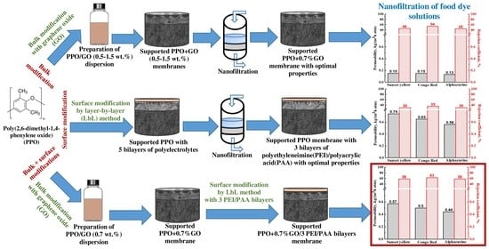
Modification Approaches of Polyphenylene Oxide Membranes to Enhance Nanofiltration Performance

1
St. Petersburg State University, 7/9 Universitetskaya nab., Saint Petersburg 199034, Russia
2
Pavlov First Saint Petersburg State Medical University, L’va Tolstogo ulitsa 6–8, Saint Petersburg 197022, Russia
*
Author to whom correspondence should be addressed.
Membranes 2023, 13(5), 534; https://doi.org/10.3390/membranes13050534
Submission received: 24 March 2023 / Revised: 2 May 2023 / Accepted: 17 May 2023 / Published: 21 May 2023
(This article belongs to the Special Issue Surface Modification and Performance Enhancement for Membranes)

Abstract

:
Presently, water pollution poses a serious threat to the environment; the removal of organic pollutants from resources, especially dyes, is very important. Nanofiltration (NF) is a promising membrane method to carry out this task. In the present work, advanced supported poly(2,6-dimethyl-1,4-phenylene oxide) (PPO) membranes were developed for NF of anionic dyes using bulk (the introduction of graphene oxide (GO) into the polymer matrix) and surface (the deposition of polyelectrolyte (PEL) layers by layer-by-layer (LbL) technique) modifications. The effect of PEL combinations (polydiallyldimethylammonium chloride/polyacrylic acid (PAA), polyethyleneimine (PEI)/PAA, and polyallylamine hydrochloride/PAA) and the number of PEL bilayers deposited by LbL method on properties of PPO-based membranes were studied by scanning electron microscopy (SEM), atomic force microscopy (AFM), and contact angle measurements. Membranes were evaluated in NF of food dye solutions in ethanol (Sunset yellow (SY), Congo red (CR), and Alphazurine (AZ)). The supported PPO membrane, modified with 0.7 wt.% GO and three PEI/PAA bilayers, exhibited optimal transport characteristics: ethanol, SY, CR, and AZ solutions permeability of 0.58, 0.57, 0.50, and 0.44 kg/(m2h atm), respectively, with a high level of rejection coefficients—58% for SY, 63% for CR, and 58% for AZ. It was shown that the combined use of bulk and surface modifications significantly improved the characteristics of the PPO membrane in NF of dyes.

Graphical Abstract

1. Introduction

Currently, water pollution poses a serious threat to the environment, and the removal of organic and toxic pollutants from resources attracts a great amount of attention from scientists [1]. The textile and food industries are the main sources of pollution, of which significantly affects the quality of available water resources due to the discharge of dyes. Dyes (more than 100,000 commercially available) are complex organic molecules widely used in industries of printing, plastics, paper, textile, food, etc. [2,3,4,5]. Most dyes are not amenable to traditional methods of purification, thereby accumulating in the environment due to their high degree of resistance to temperature, light, biodegradation, and detergents [6]. Pressure-driven membrane process nanofiltration (NF) is one of the most promising alternatives for resource purification from dyes, as it relates to sustainable processes [7]. NF is a pressure-driven membrane process between reverse osmosis (RO) and ultrafiltration (UF), and is used for removing solutes with a molecular weight in the range of 200–1000 g/mol [8,9]. A current area of intense research is the extension of NF to the separation of molecules in organic solvents, which is called organic solvent NF (OSN) [8,10] and has a great potential in industries (from refining to chemical and pharmaceutical synthesis) [11]. Both porous and non-porous (composite or supported) membranes are used for OSN [12] of the most common solvents and solutes [11], and various modification approaches are used for the development of NF membranes to increase filtration efficiency. Scientists are also actively developing mathematical models of NF to better understand transport mechanisms as well as to predict separation characteristics. For example, models based on the one-dimensional Nernst–Planck equation coupled with electroneutrality, zero current, and Donnan equilibrium conditions as well as two-dimensional Nernst–Planck, Poisson, and Navier–Stokes equations, a novel equation for salt flux obtained from the full solution-friction (SF) theory, were applied to investigate theoretically the pressure-driven transport of electrolytes through membranes [13,14].
In this work, it was decided to investigate supported membranes based on an aromatic glassy polymer poly(2,6-dimethyl-1,4-phenylene oxide) (PPO) with a high thermal and mechanical stability as well as a resistance to chemical agents [15] for NF of food dye solutions in ethanol. This polymer is actively applied as a membrane material for diffusion membrane processes (gas separation [16,17] and pervaporation [18,19,20,21]). Based on a literature review, it was found that supported membranes based on pristine (unfunctionalized) PPO have not been yet studied for NF. Its derivatives (for example, brominated and sulfonated PPO) were mainly used for NF of different electrolytes [22,23,24,25,26]. Only membranes from brominated PPO (BPPO) were developed for OSN (namely, for the rejection of dyes such as Bengal rose, Safranine T, Alizarin yellow GG, Eriochome black T, Crystal violet, Bromophenol blue, and Coomassie brilliant blue R250) [27]. Thus, the aim of this work was to investigate the developed supported PPO membrane in NF of dyes and to enhance its performance using various modification approaches: bulk (the introduction of graphene oxide (GO) into the polymer matrix) and surface (the deposition of polyelectrolytes (PEL) with layer-by-layer (LbL) technique) modifications.
The creation of a mixed matrix membrane is a promising modification method, consisting in the introduction of an organic/inorganic component into the polymer matrix. It allows a direct and flexible changing of the membrane characteristics, combining advantages of both components. In the present work, the improvement of NF PPO membrane properties was achieved by the modification with GO due to its unique structure, good dispersion in the PPO matrix, and functional (oxygen-containing) groups. The modification with GO also provides a perspective on the improvement of NF membranes for the rejection of negatively charged molecules [28]. Our previous work [21] demonstrated the use of GO as a modifier for the pervaporation PPO membrane, which led to an increased membrane permeation flux, maintaining a high level of selectivity in the dehydration of ethylene glycol.
The deposition of nano-sized PEL layers by LbL assembly is a surface modification method, which can effectively adjust the membrane performance to obtain the tailored permeability and/or selectivity [29]. The coating of PEL layers on the membrane surface leads to definite surface charge and high hydrophilicity, resulting in a strong affinity for polar molecules, which are attractive for their use in surface membrane modification. To achieve the tailored membrane performance, the characteristics of a surface-modified membrane may be varied by the choice of PEL pair, number of deposited layer, PEL charge density, pH, etc. [30,31].
Thus, the aim of this study was to develop PPO membranes with improved characteristics by the use of bulk (the introduction of GO into the polymer matrix) and surface (the deposition of PEL by LbL technique) modifications for enhanced NF of food anionic dyes. Four PEL (three cationic–polydiallyldimethylammonium chloride, polyethyleneimine, polyallylamine hydrochloride and one anionic–polyacrylic acid) with different charge densities of a PEL pair were used to carry out the surface modification of PPO membranes. The obtained membranes were investigated by various analysis methods such as scanning electron microscopy (SEM), atomic force microscopy (AFM), and contact angle measurements. The transport properties of membranes were evaluated in NF of ethanol and solutions of anionic food dyes (Sunset yellow (SY, E110), Congo red (CR, E129), and Alphazurine (AZ, E133)) with various molecular weights. The stability of the PEL layer on the membrane surface was confirmed after NF by data of FTIR, SEM, AFM and contact angle measurements.

2. Materials and Methods

2.1. Materials

Poly(2,6-dimethyl-1,4-phenylene oxide) (PPO, CAS Number: 25134-01-4, 1.06 g/mL, Sigma-Aldrich, St. Petersburg, Russia) was applied as a membrane matrix. Graphene oxide (GO, Fullerene Technologies, St. Petersburg, Russia) was applied as a modifier for the volume (bulk) modification of the PPO membrane. For the preparation of the supported PPO membranes, commercial membrane MFFC (Vladipor, Vladimir, Russia) from fluoroplast F42L was applied as a porous support. For surface modification with polyelectrolytes (PEL) of the PPO membranes by layer-by-layer (LbL) technique, polyacrylic acid (PAA, CAS Number: 9003-01-4, Mw~100,000, 35 wt.% in H2O, Sigma-Aldrich, St. Petersburg, Russia), polyallylamine hydrochloride (PAH, CAS Number: 71550-12-4, Mw~150,000, 40 wt.% in H2O, Polysciences Europe GmbH, Hirschberg an der Bergstrasse, Germany), polyethyleneimine (PEI, CAS Number: 9002-98-6, Mw~25,000, 50 wt.% in H2O, Acros Organics, Moscow, Russia), and polydiallyldimethylammonium chloride (PDADMAC, CAS Number: 26062-79-3, Mw~200,000-350,000, 20 wt.% in H2O, Sigma-Aldrich, St. Petersburg, Russia) were used. Characteristics of PEL are presented in Table 1. Chloroform (CHCl3, CAS Number: 67-66-3, 99.1 wt.%, Vekton, St. Petersburg, Russia) was used without additional treatment.

2.2. Membrane Preparation

2.2.1. Supported Membranes

The PPO/GO composites were prepared by solid-phase method: the determined amount of PPO was ground with the GO (0.5, 0.7, 1, and 1.5 wt.% with the respect to the PPO weight), followed by dissolution in chloroform to obtain a 5 wt.% solution. Supported membranes were prepared by physical adsorption method: the 5 wt.% PPO solution in chloroform and PPO/GO composite were deposited onto a porous commercial MFFC membrane for the formation of a thin dense selective layer, followed by solvent evaporation at ambient temperature for 24 h [21].

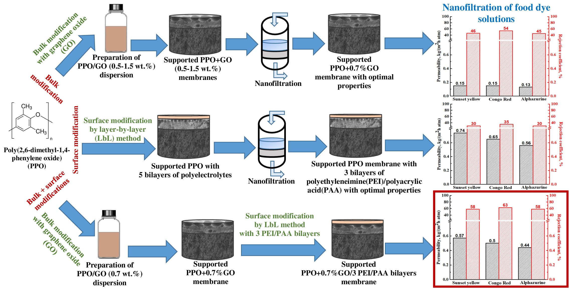
2.2.2. Surface Modification with PEL by Layer-by-Layer Technique

Surface modification of the supported membranes with PEL by LbL assembly was carried out using a Xdip-MV1 robotic coating immersion system (PROMENERGOLAB Ltd., Moscow, Russia) with the application of the PAA polyanion, and PAH, PEI, and PDADMAC polycations (10−2 mol/L in water). To prevent the exposure of the porous substrate to PEL, the supported membrane was fixed with silica gel on a Teflon plate (selective PPO layer oriented outward) and immersed alternately in PEL solutions for 10 min with water washing between the immersions [32]. The pH of the PAA and PAH solutions was adjusted to 6.5 due to maximum ionization of these weak polyelectrolytes being at this pH [31]. The polycations (PAH, PEI, and PDADMAC) were deposited initially. The membrane was washed with water several times after the deposition of the polycations. Polyanion PAA was deposited next, also followed by water rinsing. This completed the formation of one PEL bilayer on the membrane surface. The LbL modification procedure for the deposition of 1 PEL bilayer is schematically presented in Figure 1.

2.3. Nanofiltration (NF)

The developed supported membranes were evaluated in NF of food dye (Sunset yellow (SY, E110), Congo red (CR, E129), and Alphazurine (AZ, E133)) solutions in ethanol (10 mg/L), using a dead-end cell with 0.2·10−2 m2 effective area under constant stirring at ambient temperature [33]. The scheme of the NF is presented in Figure 2 [33]. NF experiments were carried out for at least a week for each membrane; every day, the membrane was tested in NF of ethanol and dye (SY, CR, and AZ) solutions, alternating them each time (namely, ethanol, SY solution, ethanol, CR solution, ethanol, AZ solution, and ethanol). Ethanol was passed between the dye solutions to confirm the stability of membrane properties. In an attempt to avoid the effects of concentration polarization, feeds were actively stirred, and ethanol was passed after each dye solution. Concentration polarization significantly decreases for dilute solutions (0.01 g/L) [34]. Within a week, the data obtained were averaged, and the membranes demonstrated the stability of the transport characteristics (the obtained average accuracies were as follows: ±5% for permeability, and ±2% for rejection coefficient).
The content of dyes in the feed and permeate was studied using a spectrophotometer PE-5400UV (EKROSKHIM, St. Petersburg, Russia), at 483 nm for Sunset yellow (E110), 505 nm for Congo red (E129), and 628 nm for Alphazurine (E133), corresponding to the absorbance maximum. The structure of dyes is presented in Table 2.
Permeability was calculated according to the following equation [35]:
L = J Δ P = m A · t · Δ P ,
where m is the weight of permeate (kg), t is permeate collection time (h), A is effective surface area of membrane (m2), and ΔP is transmembrane pressure (atm).
The rejection coefficient of dyes was calculated according to the following equation:
R = 1 C perm C feed ·   100% ,
where Cperm and Cfeed are the concentration of dyes in the permeate and the feed, respectively.

2.4. Fourier-Transform Infrared Spectroscopy (FTIR)

The structure of the upper selective layer of supported membranes was investigated using an IRAffinity-1S spectrometer (Shimadzu, St. Petersburg, Russia) with an attenuated total reflectance (ATR) accessory (PIKE Technologies, St. Petersburg, Russia) at ambient temperature in the range of 500–4000 cm−1.

2.5. Scanning Electron Microscopy (SEM)

The cross-sectional and surface morphology of supported membranes was studied using a Zeiss Merlin SEM (Carl Zeiss SMT, Oberhochen, Germany). The membrane cross-section was obtained by cleaving in liquid nitrogen.

2.6. Atomic Force Microscopy (AFM)

The surface topography of the developed membranes was investigated using an NT-MDT NTegra Maximus atomic force microscope (NT-MDT Spectrum Instruments, Moscow, Russia) in the tapping mode using standard silicon cantilevers with 15 N·m−1 rigidity.

2.7. Contact Angle Measurements

To evaluate the hydrophilic–hydrophobic surface properties, water contact angles were measured using a Goniometer LK-1 device (NPK Open Science Ltd., Krasnogorsk, Russia) by the sessile drop method. The “DropShape” software (the Laboratory of Mathematical Methods of Image Processing, Lomonosov Moscow State University, Moscow, Russia) was used to analyze results. At least three different locations were measured for each membrane, and the average contact angles were presented.

3. Results

This section is divided into three main parts. Section 3.1 is dedicated to the investigation of NF performance of the PPO-based membranes, including subsections devoted to the investigation of PPO membranes with bulk modification by GO (Section 3.1.1), with surface modification by various PEL composition and bilayer numbers (Section 3.1.2), and PPO membranes modified with GO and PEL (Section 3.1.3). The characterization of the developed supported membranes by various analysis methods is presented in Section 3.2. In Section 3.3, the comparison of NF performance of PPO-based membranes with membranes described in the literature is presented.

3.1. Nanofiltration Performance

3.1.1. Study of GO Effect

To study the effect of volume modification with GO, the supported PPO and PPO/GO (0.5–1.5 wt.%) membranes were tested in the NF of ethanol and solutions of anionic dyes (SY, CR, and AZ) with different molecular weights (Figure 3).
For all membranes, ethanol permeability was higher compared to the permeability of dye solutions due to the membrane contamination by dyes, causing membrane blocking [36]. The permeability of ethanol, SY, and CR solutions for the pristine PPO membrane was 0.237, 0.235, and 0.233 kg/(m2h atm), respectively, while the permeability of AZ decreased down to 0.182 kg/(m2h atm). It may be explained by another interaction type between the AZ and membrane selective layer: hydrophobic or hydrogen bonding, resulting in membrane blocking [36]. The introduction of GO into the PPO matrix led to a decrease in the permeability of the ethanol and dye solutions, compared to the pristine PPO membrane (Figure 3a), which intensified with the increase in GO content. This behavior can be explained by the cross-linking effect of GO on the polymer matrix [37], and the formation of GO agglomerates in the membrane matrix [38], which hindered the mass transfer of permeate components [39]. The interaction between PPO and GO was confirmed in the previous work [21].
The rejection coefficient of the membrane in NF may be explained by several mechanisms (molecular sieves, differences in diffusion and solubility, and the Donnan effect) [40]. The separation of dye molecules is mainly conditioned to their molecular weight (sieving) and electrostatic (charge) effects [41]. The increase of the molecular weight of dyes (Table 2) resulted in an increase of membrane selectivity (rejection coefficient) (Figure 3b) [10,36], except for CR dye. The highest rejection coefficient of CR for all PPO and PPO/GO membranes may be due to larger aggregates of this dye at the pH of ethanol (~6.8), as the pH solution influences the charge and structure of the CR dye molecules [42]. The modification of the PPO membrane with GO particles led to the increase of dye rejection coefficients, which increased with the increase of GO content in the PPO membrane (Figure 3b). The introduction of GO increased the rejection ability of the anionic dyes for the modified PPO/GO membranes because it led to the formation of a more negatively charged membrane surface, causing electrostatic repulsion between the dye molecules and membrane surface [40,41]. The same effect was demonstrated for NF composite membranes from polyethersulfone with graphene oxide and sulfonated graphene oxide [43]. The optimal NF performance was observed for the PPO membrane modified with 0.7 wt.% GO: the optimal ratio of permeability (0.148 kg/(m2h atm) for ethanol, and 0.157, 0.147, 0.132 kg/(m2h atm) for SY, CR, and AZ solutions, respectively) and increased dye rejection coefficients (46, 54, and 45%, for SY, CR, and AZ, respectively). Thus, this membrane was chosen for further surface modification with polyelectrolytes (PEI/PAA) to increase permeability (Section 3.1.3).

3.1.2. Study of the Effect of PEL Composition and Bilayer Number

Currently, there is no guideline for selecting commercial PEL according to the separation type being studied. In this work, only four PEL (three cationic (PDADMAC, PEI, and PAH) and one anionic (PAA)) with different charge densities of a PEL pair (Table 1) were used to carry out surface modification of the PPO membrane by LbL technique. In organic media, the charge density of a PEL pair plays the role of a physical cross-linking agent, affecting mass transfer through the surface modified membrane [31]. A total of five bilayers of PDADMAC/PAA, PAH/PAA, and PEI/PAA were deposited onto the PPO membrane and tested in the NF of ethanol and dye (SY, CR, and AZ) solutions (Figure 4).
It was demonstrated that the permeability of membranes surface-modified with five bilayers of PAH/PAA and PDADMAC/PAA decreased compared to the PPO membrane (Figure 4a), due to the high charge density of these PEL pairs (4.3 × 10⁻³ and 6.0 × 10⁻³ for PDADMAC/PAA and PAH/PAA, Table 1). The highest permeability was observed for the PPO/five bilayers of PEI/PAA membrane compared to all membranes. This may be due to the low charge density of this PEL pair (Table 1), the highest surface roughness and hydrophilicity for this membrane among surface-modified membranes (confirmed by AFM and contact angle data, presented below). Ethanol can pass through the membrane with a more effective surface area (due to high surface roughness) under pressure, forming special pathways for the transport of molecules through the relatively soft PEI/PAA layer (due to the low charge density of the PEL pair), resulting in the improved permeability [43]. The deposition of five PEL bilayers onto the PPO membrane led to the increased dye rejection coefficients (Figure 4b), attributed to the upper negatively charged PAA layer and its functional carboxylic acid groups [44]. Electrostatic repulsion between like charges (anionic PAA and dyes) is assumed [45]. However, surface modification with PEL resulted in a slight increase in dye rejection (no more than 42%). Thus, the PEI/PAA pair was chosen for surface modification of the PPO membrane in order to increase permeability in NF.
In the second step, the influence of the number of deposited bilayers of PEI/PAA (3-10 bilayers) on the performance of the surface-modified PPO membrane in the NF of ethanol and dye (SY, CR, and AZ) solutions was investigated (Figure 5).
It was shown that an increase from three to ten of the deposited number of PEI/PAA bilayers on the PPO membrane led the decrease of permeability and slight increase of dye rejection coefficients (Figure 5a,b), due to formation of a thicker upper PEL layer [43]. The PPO/3 bilayers of PEI/PAA membrane had the highest permeability (0.824, 0.737, 0.647, and 0.562 kg/(m2h atm) for ethanol, SY, CR, and AZ, respectively). The further improvement of membrane performance was carried out by a combination of bulk (the introduction of GO into the PPO matrix) and surface (coating with the optimal three PEI/PAA bilayers on the membrane surface) modifications [46].

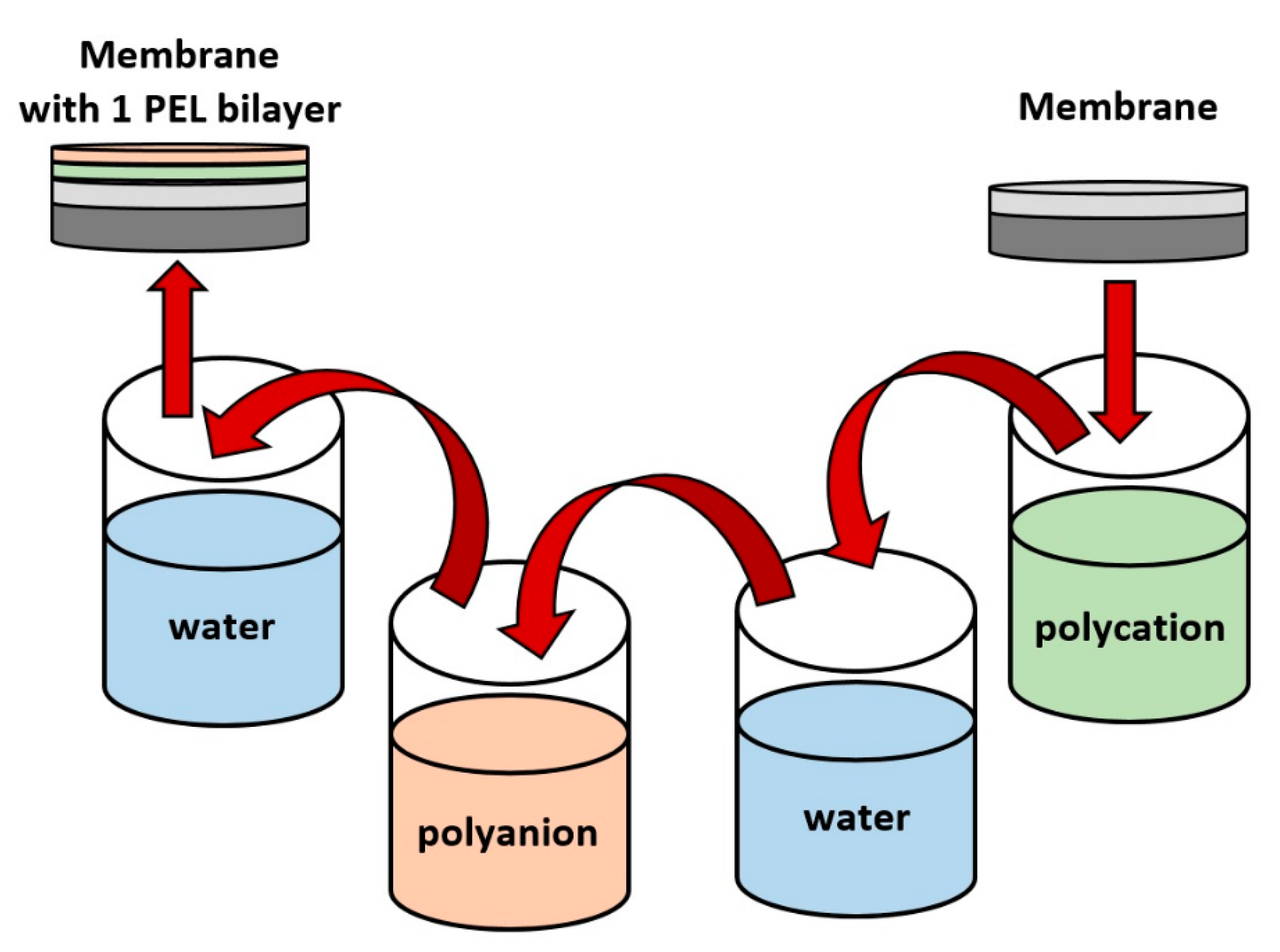
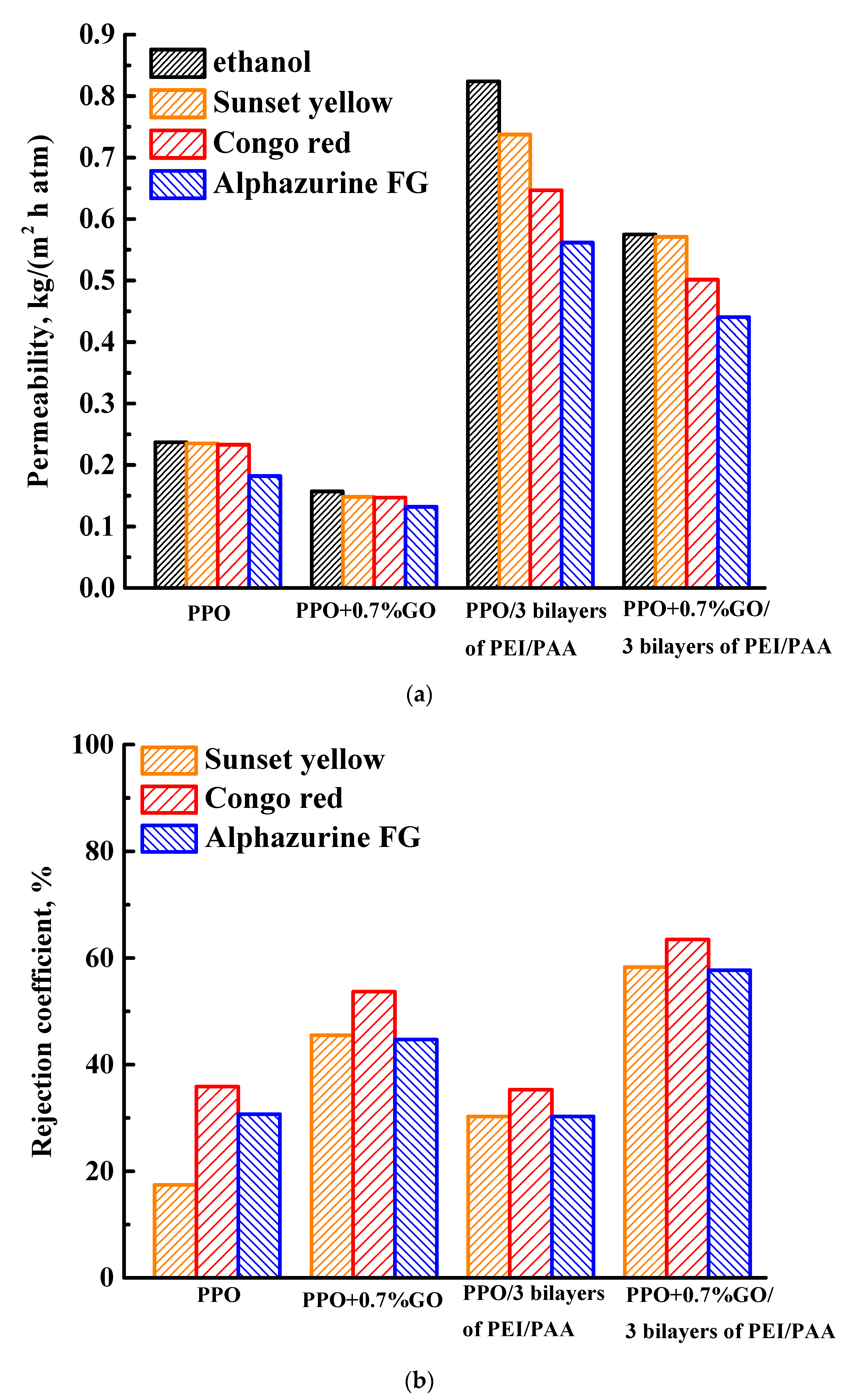
3.1.3. Study of Membranes Modified with GO and PEL

To increase permeability, the PPO + 0.7% GO membrane was surface-modified with a deposition of three bilayers of PEI/PAA and also tested in the NF of ethanol and dye (SY, CR, and AZ) solutions (Figure 6). The data of the PPO, PPO + 0.7% GO, and PPO/3 bilayers of PEI/PAA membranes were also presented in Figure 6 for comparison.
It was demonstrated that the use of bulk (the introduction of 0.7 wt.% GO into the PPO matrix) and surface modification (the deposition of three bilayers of PEI/PAA by LbL assembly) mutually was shown to result in optimal membrane performance. Specifically, the PPO + 0.7% GO/3 bilayers of PEI/PAA membrane had increased permeability 2.4 times (with an ethanol, SY, CR, and AZ solution permeability of 0.58, 0.57, 0.50, and 0.44 kg/(m2h atm), respectively) and increased dye rejection coefficients by 41, 28, and 27% (58% for SY, 63% for CR, and 58% for AZ) compared to the pristine PPO membrane. Based on previous NF data (Figure 3, Figure 4 and Figure 5), the introduction of GO into the PPO matrix and the top PAA layer (forming three PEI/PAA bilayers) results in an improved rejection ability due to the GO oxygen-containing groups and negative charge of PAA. The application of three soft PEI/PAA bilayers with a low charge density (Table 1) on the membrane surface by LBL method promotes the formation of transport channels for the transfer of ethanol in the upper PEL layer, as well as improved surface roughness and hydrophilicity of the membrane (confirmed by AFM and contact angle data, presented below), resulting in an increase in permeability. Thus, the PPO membrane modified with 0.7 wt.% GO and with the deposition of three PEI/PAA bilayers (PPO + 0.7% GO/3 bilayers of PEI/PAA) had the optimal transport properties in NF of anionic food dye solutions.

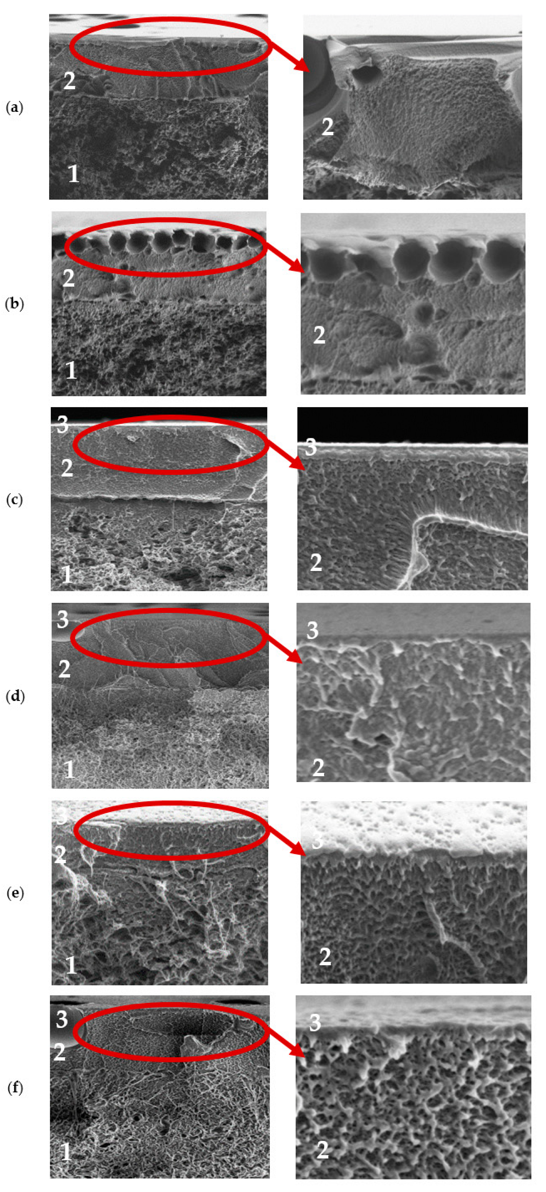
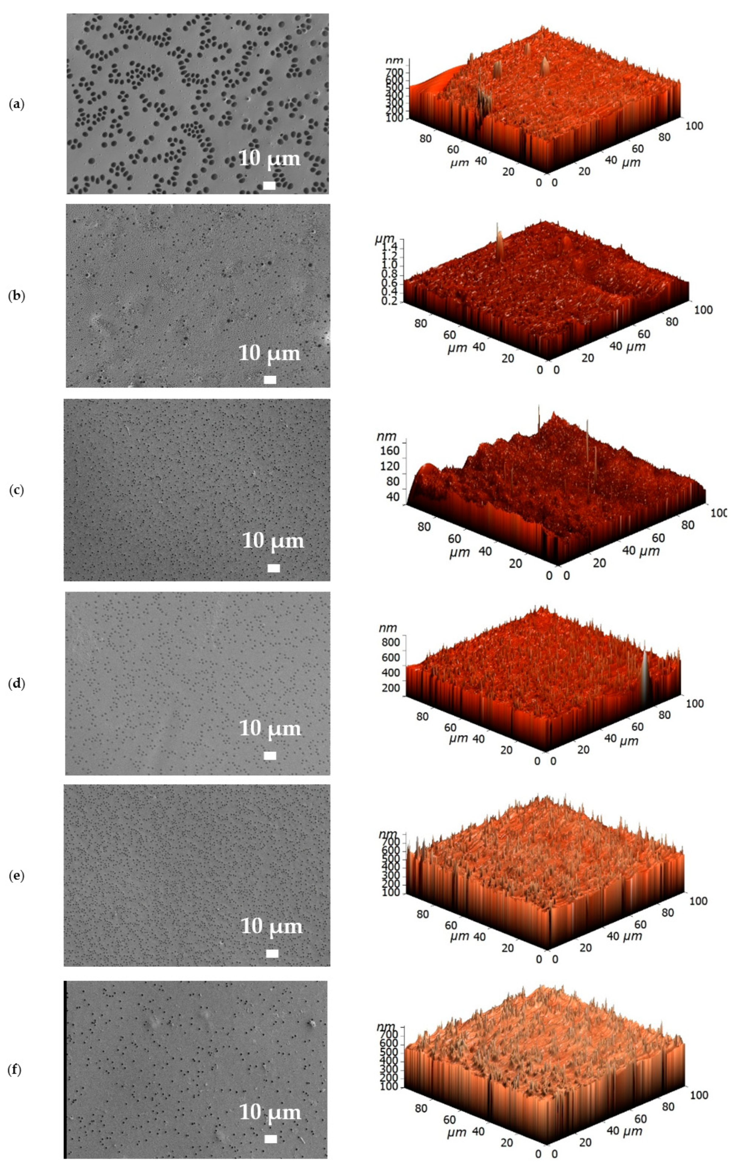
3.2. Membrane Characterization

To confirm the formation of the PEL layer and to evaluate surface parameters, supported membranes were studied by SEM, AFM, and contact angle measurements. The SEM micrographs and AFM images of the supported PPO and PPO/GO (0.7%) membranes without/with PEL modification are presented in Figure 7 and Figure 8.
For the supported PPO and PPO + 0.7% GO membranes, the cross-sectional SEM micrographs clearly demonstrate only two regions (Figure 7a,b): (1) the porous MFFC substrate, and (2) a thin dense selective layer based on the PPO and PPO/GO (0.7%) composite with a thickness of 3 ± 0.2 µm, as was also obtained in the previous work [21]. These membranes also have rounded non-perforating cavities on the surface of the thin selective layer (confirmed by SEM surface (Figure 8) and cross-sectional micrographs), which have previously been confirmed in [21,47,48]. For surface-modified membranes, there are three regions: (1) the porous MFFC substrate, (2) a thin dense selective PPO-based layer, and (3) the thinnest PEL layer with a thickness of 60 ± 10 nm (Figure 7c–f). A continuous and uniform adhesion of the thin dense PPO-based layer to the surface of the porous MFFC substrate, as well as of PEL layers to the surface of the thin dense PPO-based layer, was also observed.
The surface SEM micrographs of PPO and PPO + 0.7% GO membranes (Figure 8a,b) were also in agreement with the previously obtained data [21]; when GO is introduced, the number of cavities on the membrane surface increased, while their size decreased. The deposition of the PEL layer on the surface of PPO and PPO + 0.7% GO membranes led to their partial filling (Figure 8c–f). The surface of the supported membranes had a nodule structure, confirmed by AFM data (Figure 8). Based on AFM images, the surface parameters in terms of average (Ra) and root-mean-square roughness (Rq) were evaluated and are presented in Table 3. To assess the hydrophilic—hydrophobic balance of the membrane surface, the water contact angle of water was also measured (Table 3).
It was found that the introduction of 0.7 wt.% GO into the PPO membrane led to the increase of surface roughness parameters due to the formation of a larger number of cavities on the membrane surface, and surface hydrophilization due to the migration of hydrophilic (oxygen-containing) GO groups to the top of the membrane surface [21]. The LbL deposition of PEL bilayers (PDADMAC/PAA, PAH/PAA, PEI/PAA) onto the PPO membrane led to the slight increase of surface roughness parameters (not more than 5 nm). The PPO + 0.7% GO membrane with three deposited bilayers of PEI/PAA had a lower surface roughness compared to the pristine PPO + 0.7% GO membrane. This may be explained by the formation of a 60 nm thick PEL layer covering all irregularities of membrane surface [46]. The deposition of PEL layers onto the PPO membrane led to a decrease of the water contact angle (surface hydrophilization), because of the hydrophilic PEL nature. The PEL charge density affects the contact angle of surface-modified membranes, regardless of the sign of the surface charge [49]. The water contact angle values decreased for surface-modified PPO membranes when five bilayers were applied: PDADMAC/PAA > PAH/PAA > PEI/PAA. Despite the fact that PAA was applied last on top of all membranes, the slight difference in values was partly due to the anionic or cationic nature of the PEL charge, but mainly due to differences in the intrinsic hydrophobicity of PEL molecules [49]. The contact angles of PPO/5 bilayers of PEI/PAA and PPO + 0.7% GO/3 bilayers of PEI/PAA membranes were equal to 71° because of a 60 nm thick PEL layer on the membrane surface with the upper PAA layer. It is consistent with the properties of pristine PAA [45].
To confirm the stability of the PEL layer, the PPO + 0.7% GO/3 bilayers of PEI/PAA membrane with optimal properties was studied by FTIR, SEM, AFM, and contact angle measurements after NF.
It was demonstrated that FTIR spectra of the PPO + 0.7% GO/3 bilayers of PEI/PAA membrane before and after NF experiment were comparatively the same (Figure 9a). The SEM cross-sectional micrograph (Figure 9b) confirmed the maintenance of the PEI/PAA layer on the surface of the membrane that was uniform and did not wash off during the experiment. There was no significant changes on the PPO + 0.7% GO/3 bilayers of PEI/PAA membrane surface after NF; the surface SEM micrograph after NF (Figure 9c) was comparatively the same when compared to the one before the experiment (Figure 8f). Based on AFM image (Figure 9d), the calculated average (Ra) and root-mean-square roughness (Rq) after NF were equal to 24.8 and 50.2 nm, respectively. The PPO + 0.7% GO/3 bilayers of PEI/PAA membrane after NF had a water contact angle of 70°. Thus, the stability and preservation of the PEL layer of PPO + 0.7% GO/3 bilayers of PEI/PAA membrane after the experiment was shown.

3.3. Membrane Performance Comparison in Nanofiltration

The performance of membranes described in the literature for NF of anionic dye solutions in ethanol was compared with the developed PPO + 0.7% GO/3 bilayers of PEI/PAA membrane under close experiment conditions, including NF of dyes with similar molecular weights, in terms of permeability and rejection coefficient (Table 4).
It was demonstrated that the developed PPO + 0.7% GO/3 bilayers of PEI/PAA membrane had good performance in NF of anionic dye solutions in ethanol; it had the optimal ratio of permeability and rejection of dyes. However, it is largely inferior to TFCM in performance due to a thicker dense PPO-based layer on a porous substrate. This demonstrated the promising application of the developed PPO-based membranes in the NF of anionic dye solutions.

4. Conclusions

In the present work, the advanced supported poly(2,6-dimethyl-1,4-phenylene oxide) (PPO) membranes were developed for NF of anionic dyes using bulk (introduction of graphene oxide (GO) into the polymer matrix) and surface (deposition of polyelectrolyte (PEL) layers by layer-by-layer (LbL) technique) modifications.
Bulk modification of the PPO membrane with GO (0.5–1.5 wt.%) led to the decrease of ethanol and dye solutions permeability and to the increase of rejection coefficients due to a more negatively charged membrane surface caused by functional GO groups. The optimal NF performance was possessed by the PPO membrane modified with 0.7 wt.% GO; it had the optimal level of permeability and dye rejection coefficients.
Surface modification by the deposition of five PEL bilayers onto the PPO membrane surface led to the increased dye rejection coefficients, due to the upper negatively charged PAA layer. The permeability of membranes with five bilayers of PAH/PAA and PDADMAC/PAA decreased compared to the PPO membrane, due to the high charge density of these PEL pairs. While the PPO membrane with five deposited bilayers of PEI/PAA had the highest permeability due to forming facilitated pathways for the transport of molecules through the PEI/PAA layer, which exhibited a relatively soft structure due to its low charge density, the highest surface roughness and hydrophilicity observed among the other studied surface-modified membranes (confirmed by AFM and contact angle data). The effect of the number of PEI/PAA bilayers (3–10 bilayers) on properties of PPO membranes was also studied. The increase from three to ten of the deposited number of PEI/PAA bilayers on the PPO membrane surface led to the decrease of permeability and the slight increase of dye rejection coefficients, due to the formation of a thicker upper PEL layer. The surface modification with three bilayers of PEI/PAA was chosen as optimal, as this membrane had the highest permeability.
The further improvement of membrane performance was carried out by a combination of bulk (the introduction of 0.7 wt.% GO into the PPO matrix) and surface (coating with the optimal three PEI/PAA bilayers on the membrane surface) modifications. This membrane had increased permeability of ethanol and dye solutions 2.4 times, and increased dye rejection coefficients by 41, 28, and 27% (for SY, CR, and AZ, respectively), compared to the pristine PPO membrane in NF. Thus, it was demonstrated that the combined use of bulk and surface modifications significantly improved the characteristics of the PPO membrane in NF of anionic dye solutions.

Author Contributions

Conceptualization, M.D.; methodology, K.S., S.E. and A.P.; investigation, M.D., X.S., A.C., V.L., O.M. and A.K.; data curation, M.D.; writing—original draft preparation, M.D.; writing—review and editing, M.D. and A.P.; visualization, M.D.; supervision, M.D.; project administration, M.D.; funding acquisition, M.D. The manuscript was written through the contributions of all authors. All authors have read and agreed to the published version of the manuscript.

Funding

This research was funded by the Russian Science Foundation, grant number 21-73-00043.

Institutional Review Board Statement

Not applicable.

Data Availability Statement

Data presented in this study are available on request from the corresponding author.

Acknowledgments

The experimental work was facilitated by the equipment from the Resource Centers for Nanotechnology, Cryogenic Department, Chemical Analysis and Materials Research Centre, and Centre “Nanofabrication of Photoactive Materials (Nanophotonics)” at the St. Petersburg State University.

Conflicts of Interest

The authors declare no conflict of interest.

References

  1. Shahabuddin, S.; Sarih, N.; Afzal Kamboh, M.; Rashidi Nodeh, H.; Mohamad, S. Synthesis of Polyaniline-Coated Graphene Oxide@SrTiO3 Nanocube Nanocomposites for Enhanced Removal of Carcinogenic Dyes from Aqueous Solution. Polymers 2016, 8, 305. [Google Scholar] [CrossRef]
  2. Sen, T.K.; Afroze, S.; Ang, H.M. Equilibrium, Kinetics and Mechanism of Removal of Methylene Blue from Aqueous Solution by Adsorption onto Pine Cone Biomass of Pinus radiata. Water Air Soil Pollut. 2011, 218, 499–515. [Google Scholar] [CrossRef]
  3. Bensalah, N.; Alfaro, M.A.Q.; Martínez-Huitle, C.A. Electrochemical treatment of synthetic wastewaters containing Alphazurine A dye. Chem. Eng. J. 2009, 149, 348–352. [Google Scholar] [CrossRef]
  4. Dawood, S.; Sen, T.K.; Phan, C. Synthesis and Characterisation of Novel-Activated Carbon from Waste Biomass Pine Cone and Its Application in the Removal of Congo Red Dye from Aqueous Solution by Adsorption. Water Air Soil Pollut. 2014, 225, 1818. [Google Scholar] [CrossRef]
  5. Yagub, M.T.; Sen, T.K.; Afroze, S.; Ang, H.M. Dye and its removal from aqueous solution by adsorption: A review. Adv. Colloid Interface Sci. 2014, 209, 172–184. [Google Scholar] [CrossRef]
  6. Chequer, F.M.D.; de Oliveira, G.A.R.; Ferraz, E.R.A.; Carvalho, J.; Zanoni, M.V.B.; de Oliveir, D.P. Textile Dyes: Dyeing Process and Environmental Impact. In Eco-Friendly Textile Dyeing and Finishing; InTech: Vienna, Austria, 2013. [Google Scholar]
  7. Mondal, S.; Purkait, M.K.; De, S. Nanofiltration of Dyes. In Advances in Dye Removal Technologies; Springer: Singapore, 2018; pp. 153–197. [Google Scholar]
  8. Peeva, L.G.; Sairam, M.; Livingston, A.G. Nanofiltration Operations in Nonaqueous Systems. In Comprehensive Membrane Science and Engineering; Elsevier: Amsterdam, The Netherlands, 2010; pp. 91–113. [Google Scholar]
  9. Handbook of Membrane Separations; Pabby, A.K.; Rizvi, S.S.H.; Requena, A.M.S. (Eds.) CRC Press: Boca Raton, FL, USA, 2008; ISBN 9780429128066. [Google Scholar]
  10. Marchetti, P.; Jimenez Solomon, M.F.; Szekely, G.; Livingston, A.G. Molecular Separation with Organic Solvent Nanofiltration: A Critical Review. Chem. Rev. 2014, 114, 10735–10806. [Google Scholar] [CrossRef]
  11. Postel, S.; Spalding, G.; Chirnside, M.; Wessling, M. On negative retentions in organic solvent nanofiltration. J. Membr. Sci. 2013, 447, 57–65. [Google Scholar] [CrossRef]
  12. Vandezande, P.; Gevers, L.E.M.; Vankelecom, I.F.J. Solvent resistant nanofiltration: Separating on a molecular level. Chem. Soc. Rev. 2008, 37, 365–405. [Google Scholar] [CrossRef] [PubMed]
  13. Ryzhkov, I.I.; Minakov, A.V. Theoretical study of electrolyte transport in nanofiltration membranes with constant surface potential/charge density. J. Membr. Sci. 2016, 520, 515–528. [Google Scholar] [CrossRef]
  14. Biesheuvel, P.M.; Rutten, S.B.; Ryzhkov, I.I.; Porada, S.; Elimelech, M. Theory for salt transport in charged reverse osmosis membranes: Novel analytical equations for desalination performance and experimental validation. Desalination 2023, 557, 116580. [Google Scholar] [CrossRef]
  15. Villaluenga, J.P.G.; Godino, P.; Khayet, M.; Seoane, B.; Mengual, J.I. Pervaporation of Alcohols and Methyl tert -Butyl Ether through a Dense Poly(2,6-dimethyl-1,4-phenylene oxide) Membrane. Ind. Eng. Chem. Res. 2004, 43, 2548–2555. [Google Scholar] [CrossRef]
  16. Tyan, N.S.; Polotskaya, G.A.; Meleshko, T.K.; Yakimansky, A.V.; Pientka, Z. Influence of the Molecular Polyimide Brush on the Gas Separation Properties of Polyphenylene Oxide. Russ. J. Appl. Chem. 2019, 92, 360–366. [Google Scholar] [CrossRef]
  17. Pulyalina, A.; Rostovtseva, V.; Polotskaya, G.; Vinogradova, L.; Zoolshoev, Z.; Simonova, M.; Hairullin, A.; Toikka, A.; Pientka, Z. Hybrid macromolecular stars incorporated poly(phenylene oxide) membranes: Organization, physical, and gas separation properties. Polymer 2019, 172, 355–364. [Google Scholar] [CrossRef]
  18. Penkova, A.; Polotskaya, G.; Toikka, A. Pervaporation composite membranes for ethyl acetate production. Chem. Eng. Process. Process Intensif. 2015, 87, 81–87. [Google Scholar] [CrossRef]
  19. Polotskaya, G.; Pulyalina, A.; Lebedev, V.; Török, G.; Rudakova, D.; Vinogradova, L. Novel view at hybrid membranes containing star macromolecules using neutron scattering and pervaporation dehydration of acetic acid. Mater. Des. 2020, 186, 108352. [Google Scholar] [CrossRef]
  20. Moulik, S.; Kumar, K.P.; Bohra, S.; Sridhar, S. Pervaporation performance of PPO membranes in dehydration of highly hazardous mmh and udmh liquid propellants. J. Hazard. Mater. 2015, 288, 69–79. [Google Scholar] [CrossRef] [PubMed]
  21. Dmitrenko, M.; Chepeleva, A.; Liamin, V.; Mazur, A.; Semenov, K.; Solovyev, N.; Penkova, A. Novel Mixed Matrix Membranes Based on Polyphenylene Oxide Modified with Graphene Oxide for Enhanced Pervaporation Dehydration of Ethylene Glycol. Polymers 2022, 14, 691. [Google Scholar] [CrossRef]
  22. Tongwen, X. A novel positively charged composite membranes for nanofiltration prepared from poly(2,6-dimethyl-1,4-phenylene oxide) by in situ amines crosslinking. J. Membr. Sci. 2003, 215, 25–32. [Google Scholar] [CrossRef]
  23. Meng, N.; Zhao, W.; Shamsaei, E.; Wang, G.; Zeng, X.; Lin, X.; Xu, T.; Wang, H.; Zhang, X. A low-pressure GO nanofiltration membrane crosslinked via ethylenediamine. J. Membr. Sci. 2018, 548, 363–371. [Google Scholar] [CrossRef]
  24. Nogami, N.; Chowdhury, G.; Matsuura, T. Preparation and performance testing of sulfonated poly(phenylene oxide) based composite membranes for nanofiltration. J. Appl. Polym. Sci. 2004, 91, 2624–2628. [Google Scholar] [CrossRef]
  25. Noël, I.M.; Lebrun, R.E.; Bouchard, C.R. Nanofiltration of NaCl solutions using a SPPO membrane (BQ01) Part 1. Membrane characterization and separation mechanisms. Desalination 2003, 155, 229–242. [Google Scholar] [CrossRef]
  26. Kim, K.-J.; Chowdhury, G.; Matsuura, T. Low pressure reverse osmosis performances of sulfonated poly(2,6-dimethyl-1,4-phenylene oxide) thin film composite membranes: Effect of coating conditions and molecular weight of polymer. J. Membr. Sci. 2000, 179, 43–52. [Google Scholar] [CrossRef]
  27. Xu, Y.; Yu, S.; Peng, G.; Sotto, A.; Ruan, H.; Shen, J.; Gao, C. Novel crosslinked brominated polyphenylene oxide composite nanofiltration membranes with organic solvent permeability and swelling property. J. Membr. Sci. 2021, 620, 118784. [Google Scholar] [CrossRef]
  28. Liu, Y.; Huang, Z.; Zhang, Z.; Lin, X.; Li, Q.; Zhu, Y. A high stability GO nanofiltration membrane preparation by co-deposition and crosslinking polydopamine for rejecting dyes. Water Sci. Technol. 2022, 85, 1783–1799. [Google Scholar] [CrossRef]
  29. Joseph, N.; Ahmadiannamini, P.; Hoogenboom, R.; Vankelecom, I.F.J. Layer-by-layer preparation of polyelectrolyte multilayer membranes for separation. Polym. Chem. 2014, 5, 1817–1831. [Google Scholar] [CrossRef]
  30. Shi, G.M.; Zuo, J.; Tang, S.H.; Wei, S.; Chung, T.S. Layer-by-layer (LbL) polyelectrolyte membrane with NexarTM polymer as a polyanion for pervaporation dehydration of ethanol. Sep. Purif. Technol. 2015, 140, 13–22. [Google Scholar] [CrossRef]
  31. Morshed, M.; Zimmer, A.; Broch, L.; Alem, H.; Roizard, D. PDMS membranes modified by polyelectrolyte multilayer deposition to improve OSN separation of diluted solutes in toluene. Sep. Purif. Technol. 2020, 237, 116331. [Google Scholar] [CrossRef]
  32. Dmitrenko, M.; Kuzminova, A.; Zolotarev, A.; Ermakov, S.; Roizard, D.; Penkova, A. Enhanced pervaporation properties of PVA-based membranes modified with polyelectrolytes. application to IPA dehydration. Polymers 2020, 12, 14. [Google Scholar] [CrossRef]
  33. Kuzminova, A.; Dmitrenko, M.; Zolotarev, A.; Korniak, A.; Poloneeva, D.; Selyutin, A.; Emeline, A.; Yushkin, A.; Foster, A.; Budd, P.; et al. Novel Mixed Matrix Membranes Based on Polymer of Intrinsic Microporosity PIM-1 Modified with Metal-Organic Frameworks for Removal of Heavy Metal Ions and Food Dyes by Nanofiltration. Membranes 2021, 12, 14. [Google Scholar] [CrossRef] [PubMed]
  34. Bhattacharjee, S.; Chen, J.C.; Elimelech, M. Coupled model of concentration polarization and pore transport in crossflow nanofiltration. AIChE J. 2001, 47, 2733–2745. [Google Scholar] [CrossRef]
  35. Baker, R.W. Membrane Technology and Applications; McGraw-Hill: New York, NY, USA, 2000. [Google Scholar]
  36. Hidalgo, A.M.; León, G.; Gómez, M.; Murcia, M.D.; Gómez, E.; Macario, J.A. Removal of different dye solutions: A comparison study using a polyamide nf membrane. Membranes 2020, 10, 408. [Google Scholar] [CrossRef] [PubMed]
  37. Zakaria, Z.; Kamarudin, S.K.; Timmiati, S.N. Influence of Graphene Oxide on the Ethanol Permeability and Ionic Conductivity of QPVA-Based Membrane in Passive Alkaline Direct Ethanol Fuel Cells. Nanoscale Res. Lett. 2019, 14, 28. [Google Scholar] [CrossRef] [PubMed]
  38. Abdelhamid, A.E.; El-Sayed, A.A.; Khalil, A.M. Polysulfone nanofiltration membranes enriched with functionalized graphene oxide for dye removal from wastewater. J. Polym. Eng. 2020, 40, 833–841. [Google Scholar] [CrossRef]
  39. Church, R.B.; Hu, K.; Magnacca, G.; Cerruti, M. Cations Block Hydrogen-Bonding-Driven Ethanol Permeation through Disordered Drop-Cast Graphene Oxide Membranes. ACS Appl. Nano Mater. 2019, 2, 5389–5398. [Google Scholar] [CrossRef]
  40. Gholami, N.; Mahdavi, H. Nanofiltration composite membranes of polyethersulfone and graphene oxide and sulfonated graphene oxide. Adv. Polym. Technol. 2018, 37, 3529–3541. [Google Scholar] [CrossRef]
  41. Vaysizadeh, A.; Zinatizadeh, A.A.; Zinadini, S. Fouling mitigation and enhanced dye rejection in UF and NF membranes via layer-by-layer (LBL) assembly and altering PVP percentage as pore former. Environ. Technol. Innov. 2021, 23, 101698. [Google Scholar] [CrossRef]
  42. Hairom, N.H.H.; Mohammad, A.W.; Kadhum, A.A.H. Nanofiltration of hazardous Congo red dye: Performance and flux decline analysis. J. Water Process Eng. 2014, 4, 99–106. [Google Scholar] [CrossRef]
  43. Liu, Y.; Chen, G.Q.; Yang, X.; Deng, H. Preparation of layer-by-layer nanofiltration membranes by dynamic deposition and crosslinking. Membranes 2019, 9, 20. [Google Scholar] [CrossRef]
  44. Chiao, Y.-H.; Chen, S.-T.; Yap Ang, M.B.M.; Patra, T.; Castilla-Casadiego, D.A.; Fan, R.; Almodovar, J.; Hung, W.-S.; Wickramasinghe, S.R. High-Performance Polyacrylic Acid-Grafted PVDF Nanofiltration Membrane with Good Antifouling Property for the Textile Industry. Polymers 2020, 12, 2443. [Google Scholar] [CrossRef]
  45. Lin, Z.; Zhang, Q.; Qu, Y.; Chen, M.; Soyekwo, F.; Lin, C.; Zhu, A.; Liu, Q. LBL assembled polyelectrolyte nanofiltration membranes with tunable surface charges and high permeation by employing a nanosheet sacrificial layer. J. Mater. Chem. A 2017, 5, 14819–14827. [Google Scholar] [CrossRef]
  46. Dmitrenko, M.; Liamin, V.; Kuzminova, A.; Lahderanta, E.; Solovyev, N.; Penkova, A. Modification Approaches to Enhance Dehydration Properties of Sodium Alginate-Based Pervaporation Membranes. Membranes 2021, 11, 255. [Google Scholar] [CrossRef] [PubMed]
  47. Polotskaya, G.A.; Lebedev, V.T.; Pulyalina, A.Y.; Vinogradova, L.V. Structure and transport properties of pervaporation membranes based on polyphenylene oxide and heteroarm star polymers. Pet. Chem. 2016, 56, 920–930. [Google Scholar] [CrossRef]
  48. Rostovtseva, V.; Pulyalina, A.; Dubovenko, R.; Faykov, I.; Subbotina, K.; Saprykina, N.; Novikov, A.; Vinogradova, L.; Polotskaya, G. Enhancing Pervaporation Membrane Selectivity by Incorporating Star Macromolecules Modified with Ionic Liquid for Intensification of Lactic Acid Dehydration. Polymers 2021, 13, 1811. [Google Scholar] [CrossRef] [PubMed]
  49. Hänni-Ciunel, K.; Findenegg, G.H.; von Klitzing, R. Water Contact Angle On Polyelectrolyte-Coated Surfaces: Effects of Film Swelling and Droplet Evaporation. Soft Mater. 2007, 5, 61–73. [Google Scholar] [CrossRef]
  50. Vanherck, K.; Hermans, S.; Verbiest, T.; Vankelecom, I. Using the photothermal effect to improve membrane separations via localized heating. J. Mater. Chem. 2011, 21, 6079. [Google Scholar] [CrossRef]
  51. Yushkin, A.A.; Anokhina, T.S.; Volkov, A.V. Application of cellophane films as nanofiltration membranes. Pet. Chem. 2015, 55, 746–752. [Google Scholar] [CrossRef]
  52. Vanherck, K.; Verbiest, T.; Vankelecom, I. Comparison of Two Synthesis Routes to Obtain Gold Nanoparticles in Polyimide. J. Phys. Chem. C 2012, 116, 115–125. [Google Scholar] [CrossRef]
  53. Vanherck, K.; Vankelecom, I.; Verbiest, T. Improving fluxes of polyimide membranes containing gold nanoparticles by photothermal heating. J. Membr. Sci. 2011, 373, 5–13. [Google Scholar] [CrossRef]
  54. Li, H.; Ouyang, G.; Li, X.; Li, L.; Zhong, Z.; Cai, M.; Li, W.; Huang, W. Ultrathin Organic Solvent Nanofiltration with Polydopamine-Hkust-1 Interlayer for Organic Solvent Separation. SSRN Electron. J. 2022, 26. [Google Scholar] [CrossRef]
  55. Ma, Y.; Su, Y.; Li, Y.; Jiang, Z. Fabrication of composite nanofiltration membranes with enhanced structural stability for concentrating oligomeric proanthocyanidins in ethanol aqueous solution. Korean J. Chem. Eng. 2015, 32, 1902–1909. [Google Scholar] [CrossRef]
  56. Yang, S.; Zhen, H.; Su, B. Polyimide thin film composite (TFC) membranes via interfacial polymerization on hydrolyzed polyacrylonitrile support for solvent resistant nanofiltration. RSC Adv. 2017, 7, 42800–42810. [Google Scholar] [CrossRef]
  57. Paseta, L.; Luque-Alled, J.M.; Malankowska, M.; Navarro, M.; Gorgojo, P.; Coronas, J.; Téllez, C. Functionalized graphene-based polyamide thin film nanocomposite membranes for organic solvent nanofiltration. Sep. Purif. Technol. 2020, 247, 116995. [Google Scholar] [CrossRef]
Figure 1. Layer-by-layer (LbL) deposition scheme of one PEL bilayer.
Membranes 13 00534 g001
Figure 2. The scheme of the NF setup: 1—gas cylinder, 2—pressure regulator, 3—pressure valve, 4—feed tank, 5—membrane cell, 6—magnetic stirrer, 7—tank for permeate.
Membranes 13 00534 g002
Figure 3. (a) Permeability and (b) rejection coefficients of the supported PPO and PPO/GO membranes in NF of ethanol and dye solutions.
Membranes 13 00534 g003
Figure 4. (a) Ethanol and dye solution permeability and (b) rejection coefficients for the PPO membranes with the five deposited PEL bilayers.
Membranes 13 00534 g004
Figure 5. (a) Ethanol and dye solution permeability and (b) rejection coefficients for the PPO membranes with various numbers of PEI/PAA bilayers deposited.
Membranes 13 00534 g005
Figure 6. (a) Ethanol and dye solution permeability and (b) rejection coefficients for the PPO and PPO/GO membranes without/with the three deposited bilayers of PEI/PAA.
Membranes 13 00534 g006
Figure 7. SEM cross-sectional micrographs with magnification 10 kX and 25 kX of (a) PPO, (b) PPO + 0.7% GO, (c) PPO/5 bilayers of PDADMAC/PAA, (d) PPO/5 bilayers of PAH/PAA, (e) PPO/5 bilayers of PEI/PAA, and (f) PPO + 0.7% GO/3 bilayers of PEI/PAA membranes. 1—region of porous MFFC support, 2—region of the dense selective layer, 3—region of the PEL layer.
Membranes 13 00534 g007
Figure 8. Surface SEM micrographs and AFM images of (a) PPO, (b) PPO + 0.7% GO, (c) PPO/5 bilayers of PDADMAC/PAA, (d) PPO/5 bilayers of PAH/PAA, (e) PPO/5 bilayers of PEI/PAA, and (f) PPO + 0.7% GO/3 bilayers of PEI/PAA membranes.
Membranes 13 00534 g008
Figure 9. (a) FTIR spectra of the PPO + 0.7% GO/3 bilayers of PEI/PAA membrane before and after NF, (b) SEM cross-sectional micrograph with magnification 20 kX and 50 kX (1—region of the porous MFFC support, 2—region of the dense selective PPO/GO layer, 3—region of the PEI/PAA layer), (c) SEM surface micrograph, and (d) AFM surface image of the PPO + 0.7% GO/3 bilayers of PEI/PAA membrane after NF.
Membranes 13 00534 g009
Table 1. Main characteristics of PEL.
PAAPDADMACPAHPEI
Monomer unit(C3H4O2)n(C8H16ClN)n(CH2CH(CH2NH2 · HCl))n(C22N11H55)n
Mw unit, g/mol72161.593.5473
PEL structureMembranes 13 00534 i001Membranes 13 00534 i002Membranes 13 00534 i003Membranes 13 00534 i004
Mn a100,000200,000–350,000150,00060,000
Charge density by weight (×103) b [31]-PDADMAC/PAA
4.3
PAH/PAA
6.0
PEI/PAA
1.8
a average molecular weight; b calculated according to the formula: charge density = 1/∑Mw monomer unit of PEL.
Table 2. The structure of dyes.
DyeMolecular FormulaStructureMolar Mass,
g/mol
Sunset yellow (SY, E110)C16H10N2Na2O7S2Membranes 13 00534 i005429
Congo red
(CR, E129)
C32H22N6Na2O6S2Membranes 13 00534 i006697
Alphazurine
(AZ, E133)
C37H34Na2N2O9S3Membranes 13 00534 i007793
Table 3. Surface roughness parameters and water contact angle of membranes.
MembraneRa, nmRq, nmContact Angle of Water, °
PPO24.449.188 ± 2
PPO + 0.7% GO44.273.086 ± 2
PPO/5 bilayers of PDADMAC/PAA25.150.175 ± 2
PPO/5 bilayers of PAH/PAA26.850.974 ± 2
PPO/5 bilayers of PEI/PAA28.853.471 ± 2
PPO + 0.7% GO/3 bilayers of PEI/PAA26.453.171 ± 2
Table 4. Comparison of transport properties for membranes in NF of anionic dye solutions in ethanol.
MembraneEthanol Permeability,
kg/(m2h atm)
Dye Solution,
Concentration
Solution
Permeability,
kg/(m2h atm)
Rejection Coefficient, %Ref.
PPO + 0.7% GO/3 bilayers of PEI/PAA0.58Sunset yellow
10 mg/L
0.5758This study
Congo red
10 mg/L
0.5063
Alphazurine FG
10 mg/L
0.4458
PIM-1/MIL-125-Alphazurine FG
10 mg/L
0.1999[33]
-Sunset yellow
10 mg/L
0.1999
PIM-1/MIL-140A-Alphazurine FG
10 mg/L
0.2589
-Sunset yellow
10 mg/L
0.2391
Cellulose acetate/gold nanoparticles0.06Bromothymol
Blue
-82[50]
Cellophane0.05Remazol
Brilliant Blue R
-79[51]
Orange II-55
Polyimide (PI)/gold
nanoparticles
-Methyl Orange0.1682[52]
Bromothymol
Blue
2.358[53]
Thin-
film nanocomposite membrane (TFCM)
polyamide (PA)/polydopamine-HKUST-10.6/polyetherimide
3.6Congo red
100 mg/L
2.593[54]
Rose Bengal
100 mg/L
-91
Methyl Orange
100 mg/L
-80
TFCM
PA-polyether-
sulfone/polyvinyl formal
1.6Orange GII
100 mg/L
-68[55]
TFCM
PI/hydrolyzed polyacrylonitrile (PAN)
-Coomassie brilliant blue
100 mg/L
0.5599[56]
TFCM
PA/octadecylamine (ODA)-functionalized reduced graphene
oxide (rGO)/PI
-Sunset Yellow
20 mg/L
3.699[57]
Rose Bengal
20 mg/L
3.998
Disclaimer/Publisher’s Note: The statements, opinions and data contained in all publications are solely those of the individual author(s) and contributor(s) and not of MDPI and/or the editor(s). MDPI and/or the editor(s) disclaim responsibility for any injury to people or property resulting from any ideas, methods, instructions or products referred to in the content.

