

Monoethanolamine (MEA) Degradation: Influence on the Electrodialysis Treatment of MEA-Absorbent


 ,
,  ,
, 

Abstract
1. Introduction
2. Materials and Methods
2.1. Materials
2.2. Thermal Exposition of MEA Solution
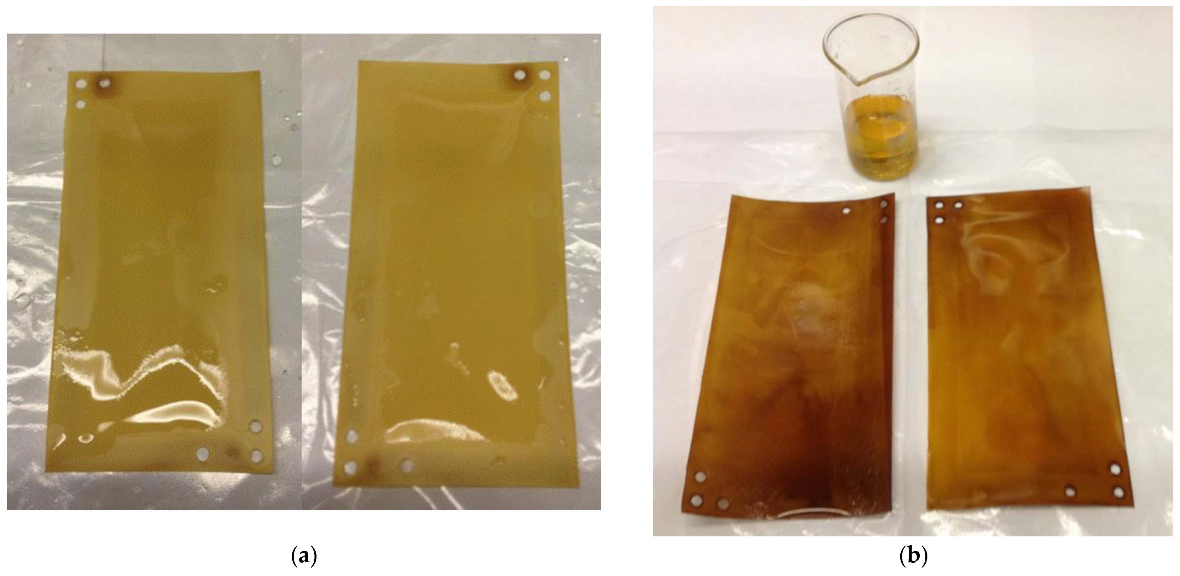
2.3. Exposure of Ion-Exchange Membranes in Degraded MEA Solution
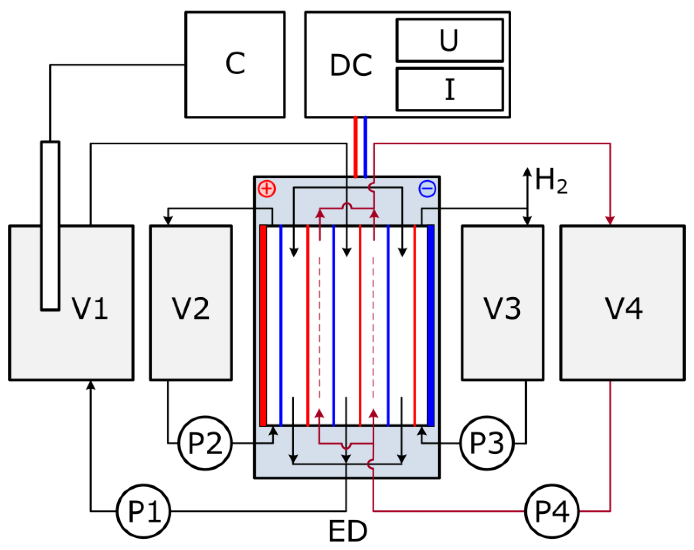
2.4. Electrodialysis
2.5. X-ray Fluorescence Analysis
3. Results and Discussion
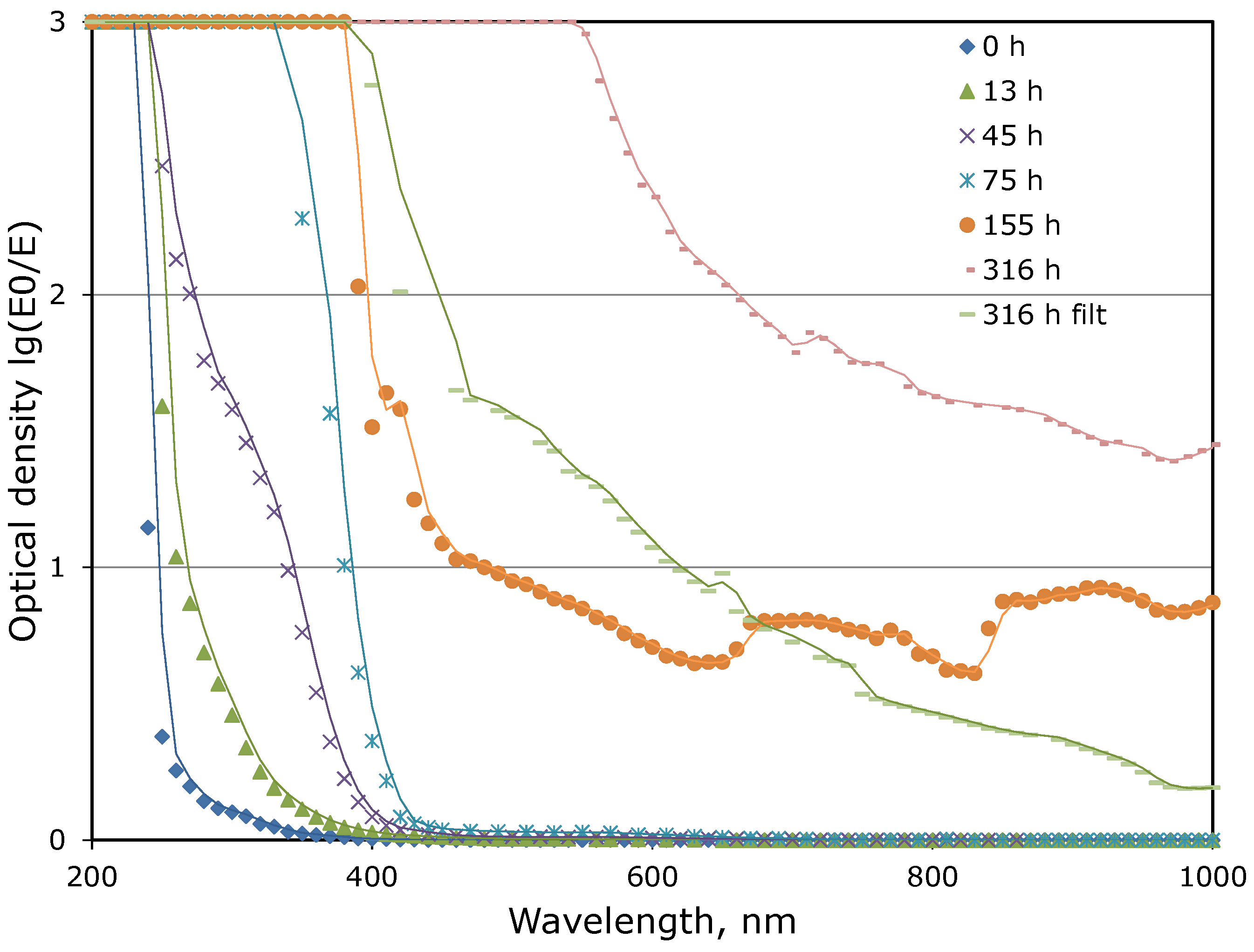
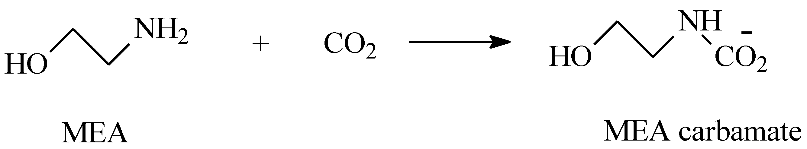
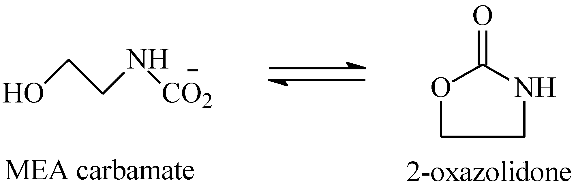
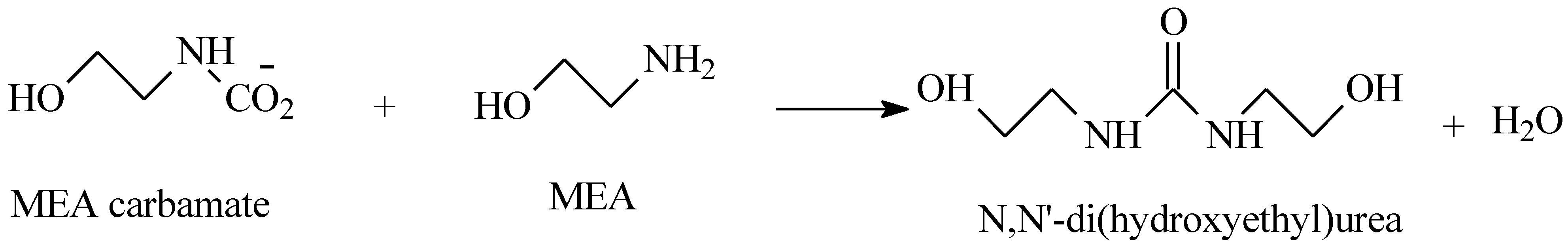
3.1. Thermal Aging of MEA Solutions
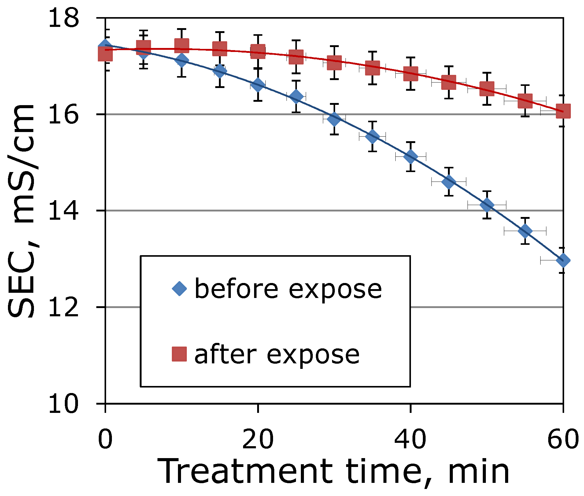
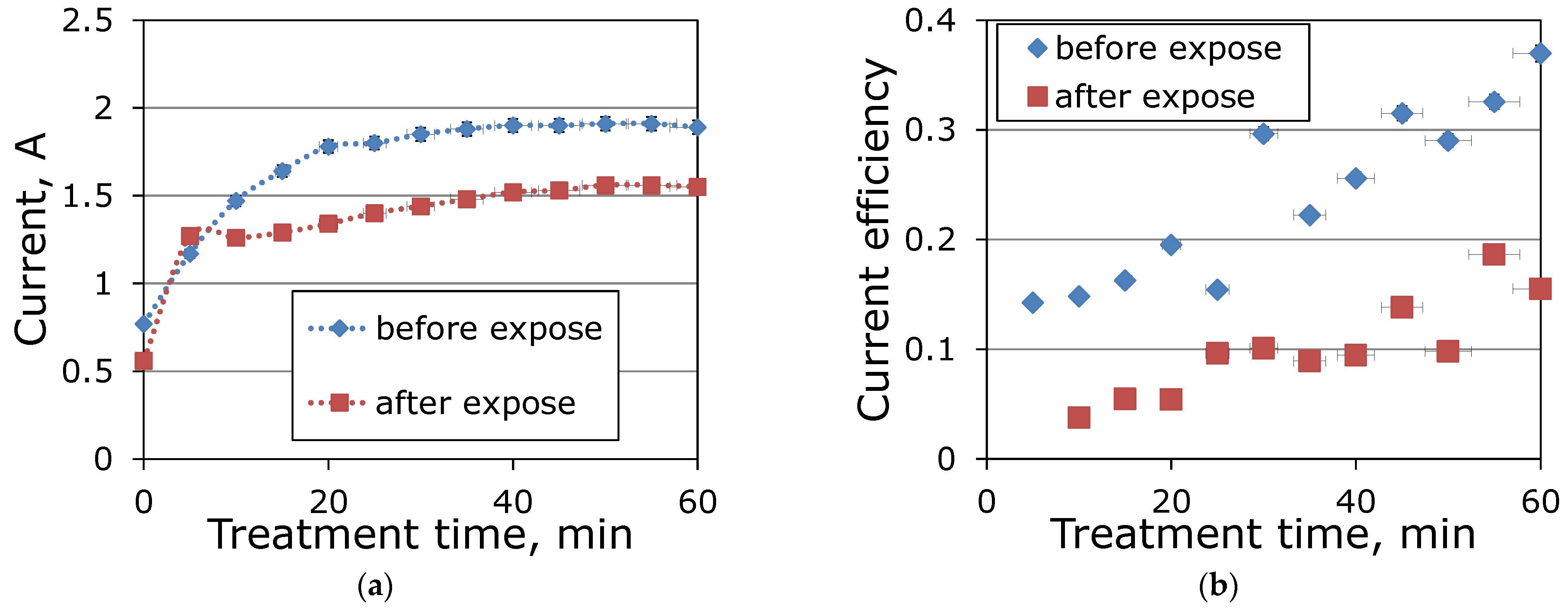
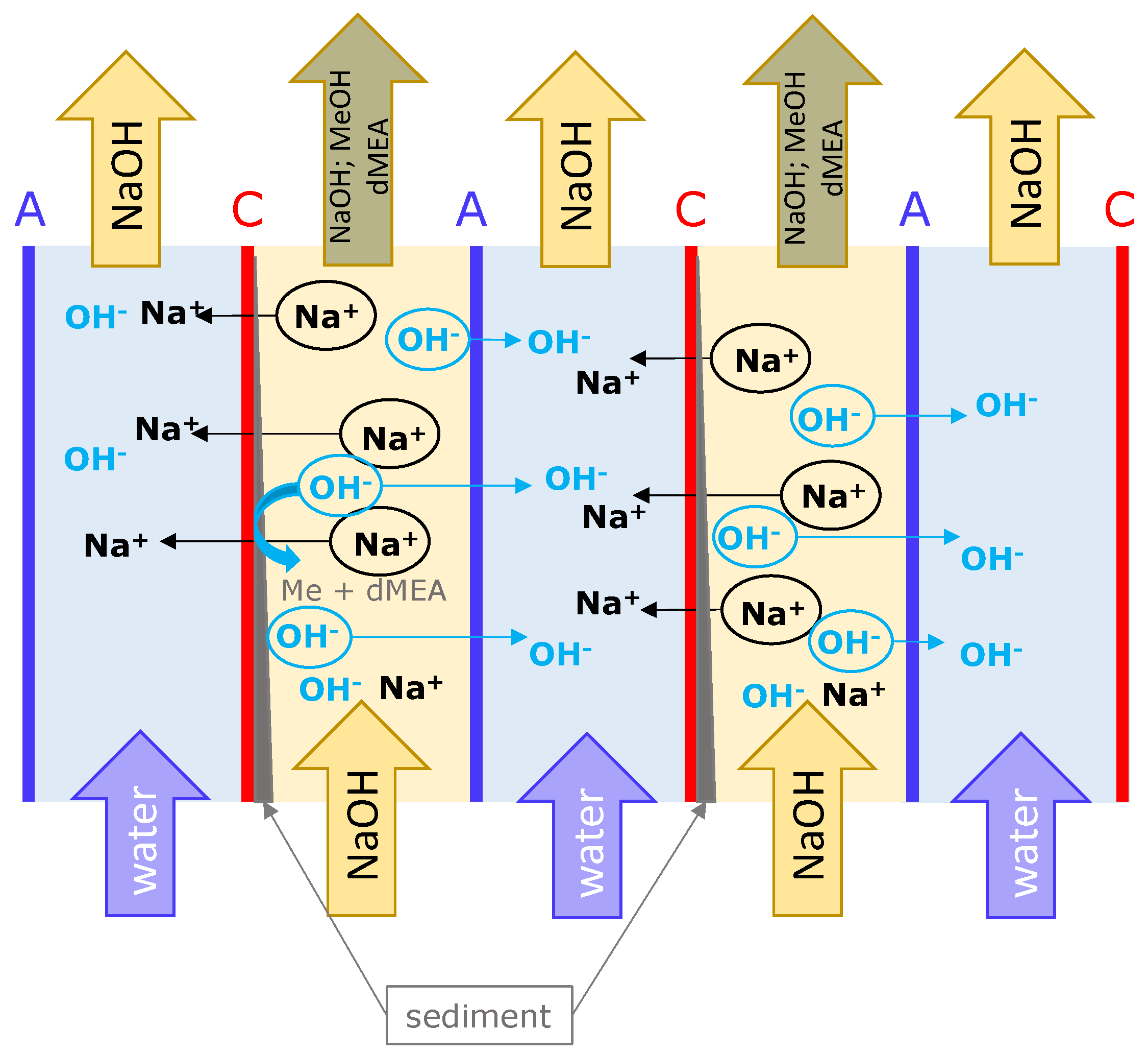
3.2. Electrokinetic Activity of MEA Degradation Products during Electrodialysis
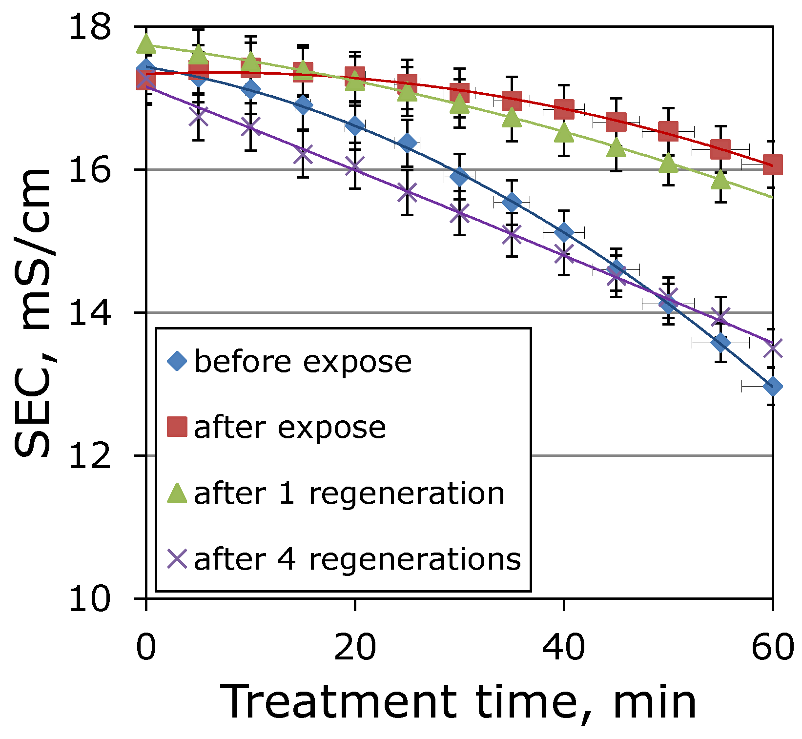
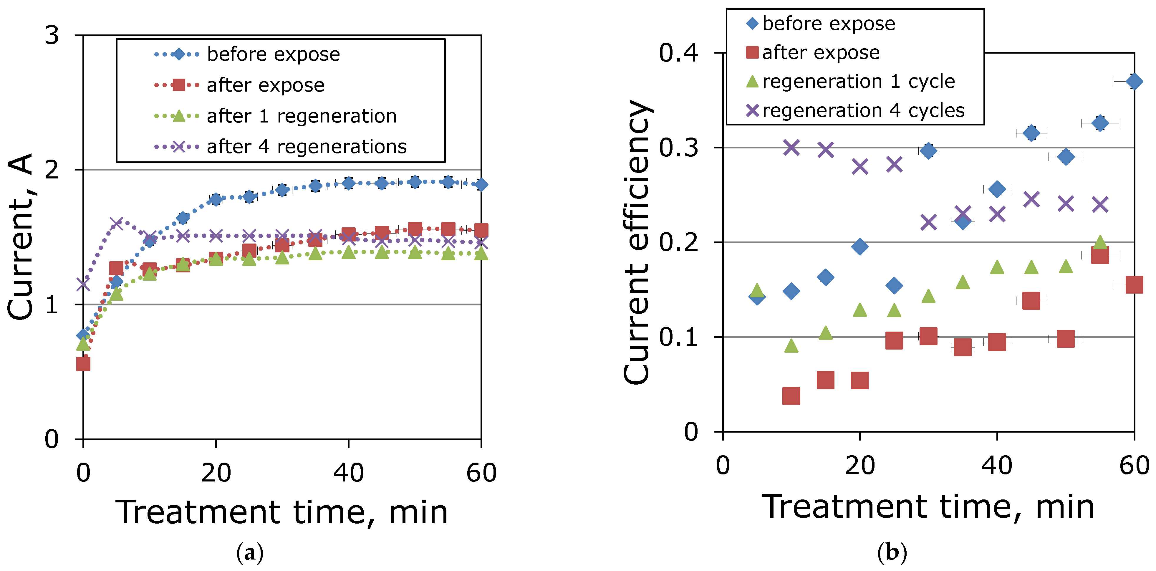
3.3. Regeneration of Ion-Exchange Membranes
4. Conclusions
Author Contributions
Funding
Institutional Review Board Statement
Data Availability Statement
Acknowledgments
Conflicts of Interest
References
- Gao, W.; Liang, S.; Wang, R.; Jiang, Q.; Zhang, Y.; Zheng, Q.; Xie, B.; Toe, C.Y.; Zhu, X.; Wang, J.; et al. Industrial carbon dioxide capture and utilization: State of the art and future challenges. Chem. Soc. Rev. 2020, 49, 8584–8686. [Google Scholar] [CrossRef]
- Rochelle, G.T. Amine Scrubbing for CO2 Capture. Science 2009, 325, 1652–1654. [Google Scholar] [CrossRef] [PubMed]
- Davis, J.; Rochelle, G. Thermal degradation of monoethanolamine at stripper conditions. Energy Procedia 2009, 1, 327–333. [Google Scholar] [CrossRef]
- Sexton, A.J.; Rochelle, G.T. Catalysts and inhibitors for MEA oxidation. Energy Procedia 2009, 1, 1179–1185. [Google Scholar] [CrossRef]
- Rochelle, G.T. Thermal degradation of amines for CO2 capture. Curr. Opin. Chem. Eng. 2012, 1, 183–190. [Google Scholar] [CrossRef]
- Gouedard, C.; Picq, D.; Launay, F.; Carrette, P.-L. Amine degradation in CO2 capture. I. A review. Int. J. Greenh. Gas Control 2012, 10, 244–270. [Google Scholar] [CrossRef]
- Buvik, V.; Høisæter, K.K.; Vevelstad, S.J.; Knuutila, H.K. A review of degradation and emissions in post-combustion CO2 capture pilot plants. Int. J. Greenh. Gas Control 2021, 106, 103246. [Google Scholar] [CrossRef]
- Moser, P.; Schmidt, S.; Stahl, K. Investigation of trace elements in the inlet and outlet streams of a MEA-based post-combustion capture process results from the test programme at the Niederaussem pilot plant. Energy Procedia 2011, 4, 473–479. [Google Scholar] [CrossRef]
- Rieder, A.; Unterberger, S. EnBW’s Post-Combustion Capture Pilot Plant at Heilbronn–Results of the First Year’s Testing Programme. Energy Procedia 2013, 37, 6464–6472. [Google Scholar] [CrossRef]
- Rieder, A.; Dhingra, S.; Khakharia, P.; Zangrilli, L.; Schallert, B.; Irons, R.; Unterberger, S.; van Os, P.; Goetheer, E. Understanding Solvent Degradation: A Study from Three Different Pilot Plants within the OCTAVIUS Project. Energy Procedia 2017, 114, 1195–1209. [Google Scholar] [CrossRef]
- Thompson, J.G.; Frimpong, R.; Remias, J.E.; Neathery, J.K.; Liu, K. Heat Stable Salt Accumulation and Solvent Degradation in a Pilot-Scale CO2 Capture Process Using Coal Combustion Flue Gas. Aerosol Air Qual. Res. 2014, 14, 550–558. [Google Scholar] [CrossRef]
- Dumée, L.; Scholes, C.; Stevens, G.; Kentish, S. Purification of aqueous amine solvents used in post combustion CO2 capture: A review. Int. J. Greenh. Gas Control 2012, 10, 443–455. [Google Scholar] [CrossRef]
- Alent’ev, A.Y.; Volkov, A.V.; Vorotyntsev, I.V.; Maksimov, A.L.; Yaroslavtsev, A.B. Membrane Technologies for Decarbonization. Membr. Membr. Technol. 2021, 3, 255–273. [Google Scholar] [CrossRef]
- Strathmann, H. Electrodialysis, a mature technology with a multitude of new applications. Desalination 2010, 264, 268–288. [Google Scholar] [CrossRef]
- Novitskii, E.G.; Vasilevskii, V.P.; Grushevenko, E.A.; Volkov, A.V.; Vasil’eva, V.I. The effect of monoethanolamine on conductivity and efficiency of electrodialysis of acid and salt solutions. Russ. J. Electrochem. 2017, 53, 391–397. [Google Scholar] [CrossRef]
- Grushevenko, E.A.; Bazhenov, S.D.; Vasilevskii, V.P.; Novitskii, E.G.; Volkov, A.V. Two-Step Electrodialysis Treatment of Monoethanolamine to Remove Heat Stable Salts. Russ. J. Appl. Chem. 2018, 91, 602–610. [Google Scholar] [CrossRef]
- Novitsky, E.G.; Vasilevsky, V.P.; Bazhenov, S.D.; Grushevenko, E.A.; Vasilyeva, V.I.; Volkov, A.V. Influence of the composition of concentrate solutions on the efficiency of carbon dioxide removal from monoethanolamine aqueous solution by electrodialysis. Pet. Chem. 2014, 54, 680–685. [Google Scholar] [CrossRef]
- Bazhenov, S.D.; Novitskii, E.G.; Vasilevskii, V.P.; Grushevenko, E.A.; Bienko, A.A.; Volkov, A.V. Heat-Stable Salts and Methods for Their Removal from Alkanolamine Carbon Dioxide Absorbents (Review). Russ. J. Appl. Chem. 2019, 92, 1045–1063. [Google Scholar] [CrossRef]
- Grushevenko, E.; Bazhenov, S.; Vasilevsky, V.; Novitsky, E.; Shalygin, M.; Volkov, A. Effect of Carbon Dioxide Loading on Removal of Heat Stable Salts from Amine Solvent by Electrodialysis. Membranes 2019, 9, 152. [Google Scholar] [CrossRef]
- Moradkhani, M.A.; Kikhavani, T.; Hosseini, S.H.; Van Der Bruggen, B.; Bayati, B. Applying intelligent approaches to estimate the removal efficiency of heat stable salts from lean amine via electrodialysis. Int. J. Greenh. Gas Control 2022, 113, 103548. [Google Scholar] [CrossRef]
- ElMoudir, W.; Supap, T.; Saiwan, C.; Idem, R.; Tontiwachwuthikul, P. Part 6: Solvent recycling and reclaiming issues. Carbon Manag. 2012, 3, 485–509. [Google Scholar] [CrossRef]
- Chen, F.; Chi, Y.; Zhang, M.; Yang, K.; Fu, C. Removal of heat stable salts from N-methyldiethanolamine wastewater using electrodialysis: A pilot-scale study. Desalination Water Treat. 2020, 195, 48–57. [Google Scholar] [CrossRef]
- Chen, F.; Chi, Y.; Zhang, M.; Liu, Z.; Fei, X.; Yang, K.; Fu, C. Removal of heat stable salts from N-methyldiethanolamine wastewater by anion exchange resin coupled three-compartment electrodialysis. Sep. Purif. Technol. 2020, 242, 116777. [Google Scholar] [CrossRef]
- Zhou, Z.; Lin, Y.; Jin, Y.; Guan, K.; Matsuyama, H.; Yu, J. Removal of heat-stable salts from lean amine solution using bipolar membrane electrodialysis. J. Membr. Sci. 2022, 645, 120213. [Google Scholar] [CrossRef]
- Huang, C.; Xu, T.; Jacobs, M.L. Regenerating flue-gas desulfurizing agents by bipolar membrane electrodialysis. AIChE J. 2006, 52, 393–401. [Google Scholar] [CrossRef]
- Karpenko, T.V.; Kovalev, N.V.; Sheldeshov, N.V.; Zabolotsky, V.I. Investigation of the Diethylamine Producing Process from its Salt by Bipolar Electrodialysis. Membr. Membr. Technol. 2022, 4, 59–68. [Google Scholar] [CrossRef]
- Melnikov, S.S.; Mugtamov, O.A.; Zabolotsky, V.I. Study of electrodialysis concentration process of inorganic acids and salts for the two-stage conversion of salts into acids utilizing bipolar electrodialysis. Sep. Purif. Technol. 2020, 235, 116198. [Google Scholar] [CrossRef]
- Skolotneva, E.; Tsygurina, K.; Mareev, S.; Melnikova, E.; Pismenskaya, N.; Nikonenko, V. High Diffusion Permeability of Anion-Exchange Membranes for Ammonium Chloride: Experiment and Modeling. Int. J. Mol. Sci. 2022, 23, 5782. [Google Scholar] [CrossRef]
- Merle, G.; Wessling, M.; Nijmeijer, K. Anion exchange membranes for alkaline fuel cells: A review. J. Membr. Sci. 2011, 377, 1–35. [Google Scholar] [CrossRef]
- Rybalkina, O.A.; Tsygurina, K.A.; Sarapulova, V.V.; Mareev, S.A.; Nikonenko, V.V.; Pismenskaya, N.D. Evolution of Current–Voltage Characteristics and Surface Morphology of Homogeneous Anion-Exchange Membranes during the Electrodialysis Desalination of Alkali Metal Salt Solutions. Membr. Membr. Technol. 2019, 1, 107–119. [Google Scholar] [CrossRef]
- Bazhenov, S.; Rieder, A.; Schallert, B.; Vasilevsky, V.; Unterberger, S.; Grushevenko, E.; Volkov, V.; Volkov, A. Reclaiming of degraded MEA solutions by electrodialysis: Results of ED pilot campaign at post-combustion CO2 capture pilot plant. Int. J. Greenh. Gas Control 2015, 42, 593–601. [Google Scholar] [CrossRef]
- Zabolotskii, V.; Sheldeshov, N.; Melnikov, S. Heterogeneous bipolar membranes and their application in electrodialysis. Desalination 2014, 342, 183–203. [Google Scholar] [CrossRef]
- Wang, Y.; Li, W.; Yan, H.; Xu, T. Removal of heat stable salts (HSS) from spent alkanolamine wastewater using electrodialysis. J. Ind. Eng. Chem. 2018, 57, 356–362. [Google Scholar] [CrossRef]
- Apel, P.Y.; Velizarov, S.; Volkov, A.V.; Eliseeva, T.V.; Nikonenko, V.V.; Parshina, A.V.; Pismenskaya, N.D.; Popov, K.I.; Yaroslavtsev, A.B. Fouling and Membrane Degradation in Electromembrane and Baromembrane Processes. Membr. Membr. Technol. 2022, 4, 69–92. [Google Scholar] [CrossRef]
- Gerzeliev, I.M.; Temnikova, V.A.; Saitov, Z.A.; Asylbaev, D.F.; Baskhanova, M.N. Synthesis of a Catalyst for Isobutane/Butylenes Alkylation Promising for Industrial Application. Pet. Chem. 2020, 60, 1170–1175. [Google Scholar] [CrossRef]


| Membrane | MA-41 | MK-40 |
|---|---|---|
| Type | Heterogeneous composite containing up to 65% anionite AV-17. Binder—polyethylene. Reinforcement—nylon mesh. | Heterogeneous composite containing up to 65% cationite KU-2. Binder—polyethylene. Reinforcement—nylon mesh. |
| Functional groups | -N+(CH3)3 | -SO3− |
| Tensile strength, MPa | >11.0 | >11.9 |
| Surface electrical resistance, Ω·cm2 | <10.0 | <10.0 |
| Transfer number in 0.01 M NaCl, fractions | >0.94 | >0.98 |
| Total static exchange capacity of dry membrane, 0.1 M HCl (or NaOH), mg-eq/g | 2.0 ± 0.3 | 2.6 ± 0.3 |
Moisture content, %
| 6.5 28.5 | 5.6 29.3 |
Density, g/cm3
| 1.27 1.16 | 1.25 1.16 |
Size change during swelling, %
| 6 ± 3 30 ± 5 | 8 ± 2 30 ± 5 |
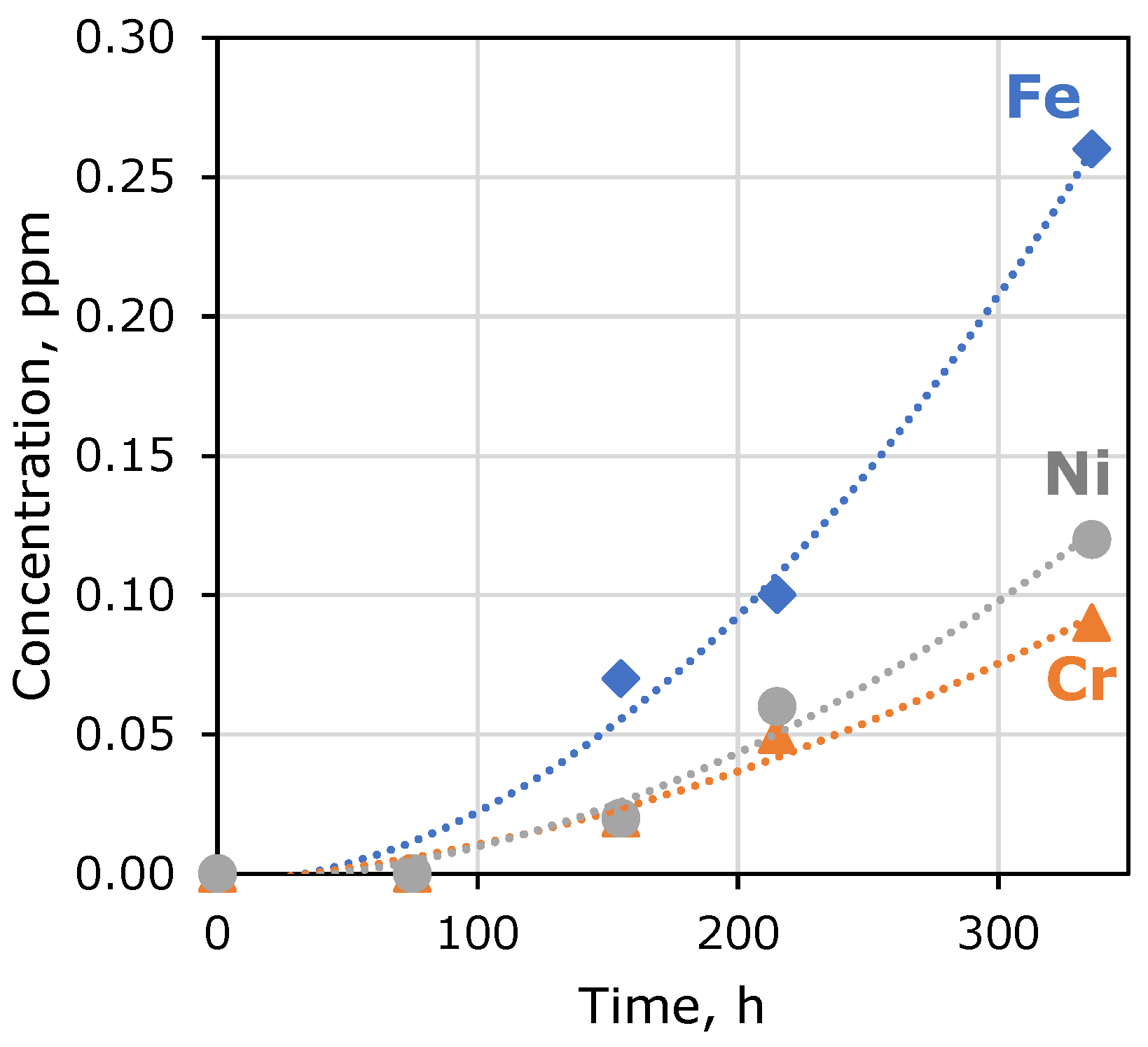
| Exposure Time, h | Fe Concentration, ppm | Cr Concentration, ppm | Ni Concentration, ppm |
|---|---|---|---|
| 0–75 | - | - | - |
| 75–155 | 0.07 | 0.02 | 0.02 |
| 155–215 | 0.10 | 0.05 | 0.06 |
| 215–336 | 0.26 | 0.09 | 0.12 |
| Membranes | Removal Depth, % | Relative Removal Depth, % | Integral Current Efficiency |
|---|---|---|---|
| Initial | 25.5 | 100 | 0.25 |
| After 6-month exposure | 16.8 | 66 | 0.10 |
| After 1 cycle of alkaline regeneration | 19.0 | 75 | 0.18 |
| After 4 cycles of alkaline regeneration | 23.0 | 90 | 0.24 |
Disclaimer/Publisher’s Note: The statements, opinions and data contained in all publications are solely those of the individual author(s) and contributor(s) and not of MDPI and/or the editor(s). MDPI and/or the editor(s) disclaim responsibility for any injury to people or property resulting from any ideas, methods, instructions or products referred to in the content. |
© 2023 by the authors. Licensee MDPI, Basel, Switzerland. This article is an open access article distributed under the terms and conditions of the Creative Commons Attribution (CC BY) license (https://creativecommons.org/licenses/by/4.0/).
Share and Cite
Novitsky, E.G.; Grushevenko, E.A.; Borisov, I.L.; Anokhina, T.S.; Bazhenov, S.D. Monoethanolamine (MEA) Degradation: Influence on the Electrodialysis Treatment of MEA-Absorbent. Membranes 2023, 13, 491. https://doi.org/10.3390/membranes13050491
Novitsky EG, Grushevenko EA, Borisov IL, Anokhina TS, Bazhenov SD. Monoethanolamine (MEA) Degradation: Influence on the Electrodialysis Treatment of MEA-Absorbent. Membranes. 2023; 13(5):491. https://doi.org/10.3390/membranes13050491
Chicago/Turabian StyleNovitsky, Eduard G., Evgenia A. Grushevenko, Ilya L. Borisov, Tatiana S. Anokhina, and Stepan D. Bazhenov. 2023. "Monoethanolamine (MEA) Degradation: Influence on the Electrodialysis Treatment of MEA-Absorbent" Membranes 13, no. 5: 491. https://doi.org/10.3390/membranes13050491
APA StyleNovitsky, E. G., Grushevenko, E. A., Borisov, I. L., Anokhina, T. S., & Bazhenov, S. D. (2023). Monoethanolamine (MEA) Degradation: Influence on the Electrodialysis Treatment of MEA-Absorbent. Membranes, 13(5), 491. https://doi.org/10.3390/membranes13050491