Article

Exergetic Performance Coefficient Analysis and Optimization of a High-Temperature Proton Exchange Membrane Fuel Cell

College of Automobile and Traffic Engineering, Nanjing Forestry University, Nanjing 210037, China
*
Author to whom correspondence should be addressed.
Membranes 2022, 12(1), 70; https://doi.org/10.3390/membranes12010070
Submission received: 29 November 2021 / Revised: 27 December 2021 / Accepted: 3 January 2022 / Published: 5 January 2022
(This article belongs to the Special Issue Membranes in Electrochemistry Applications)

Abstract

:
Performance of a high-temperature proton exchange membrane fuel cell (HT-PEMFC) and the influence of different parameters on HT-PEMFC is analyzed in this study. Firstly, mathematical expression for energy efficiency, power density, exergy destruction and exergetic performance coefficient (EPC) are derived. Then, the relationship between the dimensionless power density, exergy destruction rate, exergetic performance coefficient (EPC) and energy efficiency is compared. Furthermore, the effect of flow rate, doping level, inlet pressure and film thickness are considered to evaluate the performance of HT-PEMFC. Results show that EPC not only considers exergetic loss rate to minimize exergetic loss, but also considers the power density of HT-PEMFC to maximize its power density and improve its efficiency, so EPC represents a better performance criterion. In addition, increasing inlet pressure and doping level can improve EPC and energy efficiency, respectively.

1. Introduction

Among fuel cell types, the proton exchange membrane fuel cell (PEMFC) has been widely used in mobile units and automobiles. A low-temperature proton exchange membrane fuel cell (LT-PEMFC) operates at around 80 °C and is used in fuel cell vehicles. Compared with LT-PEMFC, an HT-PEMFC operates at 120–200 °C and has a lot of advantages, such as higher CO tolerance [1,2], simplified water and heat management [3] and enhanced kinetics [4]. Hence, many studies [5,6,7,8,9,10] have been devoted to the HT-PEMFC.
Finite time thermodynamics (FTT) has been used to analyze various thermodynamic processes and cycles [11,12,13,14,15,16,17,18,19,20,21] for several decades. The electrochemical model of PEMFC can also be embodied into corresponding FTT model for thermodynamic performance analysis and optimization to pursue maximum performances under operation conditions. Currently, typical optimal FTT objective functions include exergy loss [22], exergy efficiency [23,24,25,26], ecological performance coefficient [14,20,26,27,28,29,30,31,32,33,34,35,36], ecological function [14] and entropy production rate [22,26]. Watowich et al. [37] used the optimal control theory to determine the limit of the fuel cell operation process. Sieniutycz et al. [38,39] established a steady-state model of the fuel cell and predicted the maximum power output from the perspective of thermodynamic optimization. Liu et al. [25] developed a PEMFC power system and established a FTT model including exergy destruction, exergy efficiency and ecological function et. al. Results showed that fuel cell stack and heat exchanger were the two components that caused the greatest exergy loss. Low current density can improve the ecological performance and the power and exergetic efficiency of the system, but reduce the exergy loss and the net power of the system. Ye et al. [23] analyzed the performance of an HT-PEMFC under different operating conditions by exergy analysis, and the results showed that higher operating temperature was beneficial to improve the efficiency and power of the system, but relative humidity and operating pressure had little influence on the system. Li et al. [14] analyzed the ecological performance of PEMFC and obtained the ecological performance coefficient E C O P = P / T σ and ecological objective function E C O P = P T σ , which were defined as the ratio of power to power loss and the difference between power and power loss respectively. Guo et al. [24] obtained the optimal operation region of an HT-PEMFC under different parameters based on the maximum power density and did not compare different performance indexes and determine the optimal performance indexes. Akkaya et al. [40] defined a novel exergetic performance coefficient (EPC) which was used to analyze the performances of solid oxide fuel cell (SOFC) and compare it with other performance criteria. It is a thermal-ecological index that combines the functions of energy and exergy parameters. Therefore, EPC can be expected to better evaluate thermodynamic processes and cycles including HT-PEMFCs than the ecological performance coefficient and ecological objective function.
The purpose of this study is to evaluate HT-PEMFC by exergetic performance coefficient (EPC) and compare it with other FTT indexes. Firstly, the HT-PEMFC model is established which takes three kinds of polarization losses and leakage current density into account. Then, the relationships between EPC, power density, exergy destruction rate and energy efficiency are obtained. Finally, inlet pressure, doping level and film thickness are taken as important operating parameters to evaluate their influence on HT-PEMFC performances.

2. Exergetic Performance Coefficient (EPC) of High-Temperature Proton Exchange Membrane Fuel Cell (HT-PEMFC)

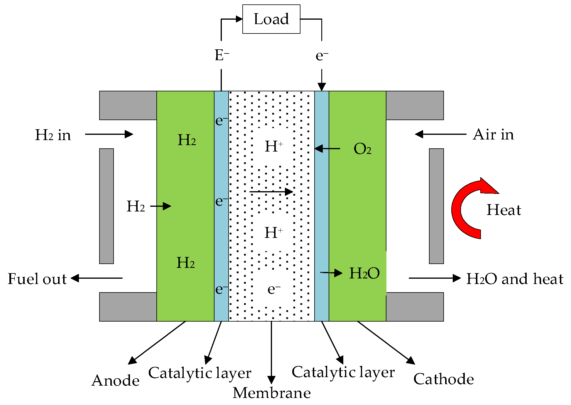
2.1. Working Principle of HT-PEMFC

The structure and working principle of HT-PEMFC are shown in Figure 1 [26], which mainly includes an anode, cathode, electrolyte and external load. The electrochemical reaction equations of the HT-PEMFC are:
Anode   rection :   H 2 2 H + + 2 e
Cathodic   reaction :   2 H + + 1 2 O 2 + 2 e H 2 O + heat
Total   reaction :   H 2 + 1 2 O 2 H 2 O + heat + electricity
According to the working principle of HT-PEMFC, the hydrogen and air flow rate can be expressed as follows:
m H 2 ˙ = S T a j A 2 F
m air ˙ = S T c j A 4 · 0.21 · F
where S T a and S T c are hydrogen stoichiometry and air stoichiometry respectively; j is current density; A is the cell active area; F is Faraday constant.

2.2. Thermodynamic Model of HT-PEMFC

The HT-PEMFC model is formulated on the basis of the following assumptions:
(1)
The HT-PEMFC system is working under steady-state conditions;
(2)
Kinetic and potential energy are neglected;
(3)
All gases within the HT-PEMFC are assumed to be ideal gas;
(4)
The environment condition is 1.013 bar (1 atm) and 25 °C; air consists of 79% nitrogen and 21% oxygen;
(5)
Anode outlet temperature is equal to the operating temperature;
(6)
There is no leakage of hydrogen and oxygen within the HT-PEMFC structure.
For the HT-PEMFC, reversible potential can be given as Equation (6):
E r = E r 0 + Δ S n F ( T T 0 ) + R T n F ln ( p H 2 p O 2 0.5 p H 2 O )
In Equation (6), E r 0 is the ideal standard potential [26]; Δ S is the change of standard molar entropy [26]; T is the operating temperature of HT-PEMFC; R is the gas constant.
For the HT-PEMFC, due to three types of overpotential which includes activation overpotential E a c t , concentration overpotential E c o n and ohmic overpotential E o h m , its actual output voltage is generally less than the reversible [26]. The actual output voltage can be shown as Equation (7):
E c e l l = E r E a c t E o h m E c o n
The power density of the HT-PEMFC can be derived as:
P = E c e l l · j · A
where j is current density and A is the electrode effective surface area.
As an energy conversion device, the output efficiency [26] of HT-PEMFC can be shown as Equation (9):
η = P Δ H ˙
where Δ H ˙ is the total energy absorbed from hydrogen and oxygen [26], it can be expressed as:
Δ H ˙ = j A Δ h n F
where Δ h is the change of molar enthalpy.
The heat leakage rate [24] from HT-PEMFC to the environment can be represented by:
Q ˙ L = K L A L ( T T 0 )
where K L and A L represent the heat leakage coefficient and the corresponding heat leakage area, respectively. T and T 0 are, respectively, the temperature of the HT-PEMFC and the environment.
According to the first law of thermodynamics, the remaining part of the thermal rate from the HT-PEMFC can be expressed as:
Q ˙ H = Δ H ˙ P Q ˙ L = A n F [ ( 1 η ) j Δ h b 1 ( T T 0 ) ]
where b 1 = n F K L A L A [24,41].

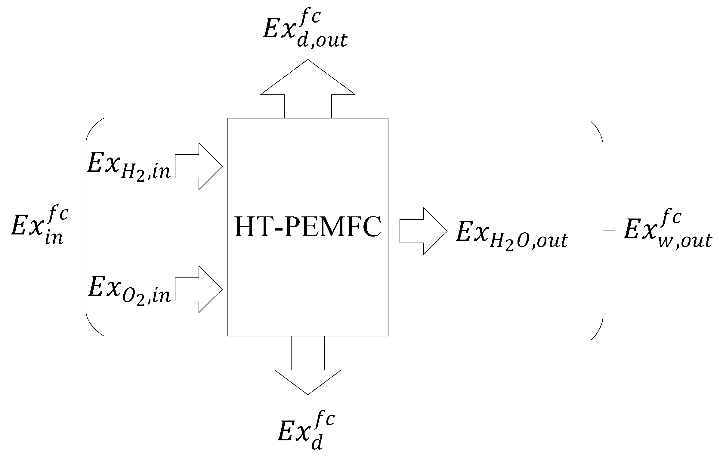
2.3. Exergetic Performance Analysis

The output performance of HT-PEMFC is degraded due to different irreversibilities including heat loss, friction between gas and channel, fuel mixing, leakage current, electrochemical reaction, and polarization. Exergetic analysis provides a standard for evaluating the quality of energy released by HT-PEMFC and can represent the actual useful work of energy.
The exergetic equilibrium equation of HT-PEMFC includes the total exergy of hydrogen and oxygen E x i n f c , output power of HT-PEMFC E x d , o u t f c , exergetic loss generated by water E x w , o u t f c , and irreversible heat loss E x d f c . Figure 2 shows the exergetic equilibrium of HT-PEMFC. The exergetic equilibrium equation of HT-PEMFC is shown as Equation (13) [40]:
E x i n f c = E x d , o u t f c + E x w , o u t f c + E x d f c
For HT-PEMFC, only physical exergy and chemical exergy is considered in the exergy of HT-PEMFC reaction process. The expression of the total exergy can be written as:
e x = ( e x ) p h + ( e x ) c h
Physical exergy [42,43] and chemical exergy [22,42] are expressed as:
( e x ) p h = ( h h 0 ) T 0 ( s s 0 )
( e x ) c h = x n · e n c h + R T 0 x n · l n x n  
where x n and e n c h are the molar fraction and the standard chemical exergy of H 2 , O 2 and H 2 O , respectively.
In HT-PEMFC, the total input exergy rate and the output exergy rate are shown as follows:
e x ˙ i n = j A n F ( e x H 2 + 0.5 e x O 2 )
e x ˙ o u t = j A n F e x H 2 O
In practical application, energy depreciation is inevitable, including heat transfer, chemical reaction friction and polarization. These irreversibilities will lead to exergetic loss. Exergetic loss can be used to measure the degree of irreversibility of the process. The greater exergetic loss, the greater irreversibility of HT-PEMFC thermodynamic process, and the less effective utilization of exergy. Exergy destruction rate of the HT-PEMFC can be expressed as [43]:
E x D = e x ˙ i n e x ˙ o u t P + Q ˙ H ( 1 T 0 / T )
In the HT-PEMFC system, energy analysis can provide necessary fuel consumption information, while exergetic performance analysis can evaluate the impact of irreversibility in the system. From the perspective of better performance and ecology, an evaluation index including energy and exergetic performance is defined as an alternative standard, which is more conducive to engineering decisions and can be derived as [40]:
E P C = P E x D = E c e l l · j · A e x ˙ i n e x ˙ o u t P + Q ˙ H ( 1 T 0 / T )
At the same time, due to the numerical differences among various indicators, in order to better compare the relationship between E P C ,   P ,   η and E x D , dimensionless method is adopted for the numerical calculation and analysis. The dimensionless function of E P C ,   P ,   E x D and η are E P C ¯ = E P C / E P C m a x , P ¯ = P / P m a x , E x D ¯ = E x D / E x D m a x and   η ¯ = η / η m a x .

2.4. Optiaml Exergy Performance Coefficient

In order to find the performance limit of HT-PEMFC and the balance between energy and exergy, this paper optimized the dimensionless power density, efficiency, exergy loss rate and EPC of HT-PEMFC [44,45,46,47,48,49]. The doping level ( D L ) , relative humidity ( R H ) , inlet pressure ( p ) and film thickness ( t m e m ) corresponding to the optimal performance of HT-PEMFC are obtained.
The current density, inlet pressure, film thickness and doping level are taken as the constraints condition of the dimensionless E P C . The expression is E P C ¯ = f ( j ,   p ,   R H , D L , t m e m ) . When j ,   p ,   R H ,   t m e m are constant, the expression is E P C ¯ = g ( D L ) .
Therefore, the value of D L o p t can be determined under optimal EPC performance. However, using mathematical method and numerical algorithm, selecting E P C as objective function when j , D L ,   R H , t m e m or j , D L ,   R H , p is given, with the constraints p or t m e m , one can obtain the optimal EPC at an optimal p o p t or t m e m o p t .

3. Results and Discussion

The relevant parameters used in the HT-PEMFC model refer to the literature [22,26] as shown in Table 1. Moreover, parametric studies are performed to investigate the HT-PEMFC performance. According to Refs. [21,22,26], the variation ranges of operating pressure p , doping level D L and film thickness t m e m are listed in Table 2.

3.1. Comparsion of Relationship between E P C , P , E x D and η

It can be seen from Figure 3 when E P C reaches the maximum value, the efficiency is 0.34, E x D / E x D m a x is 0.4 and P / P m a x is 0.9414. This means the power density at E P C m a x is very close to the maximum. When P is at its maximum value, the efficiency is 0.27, E x D / E x D m a x is 0.53 and E P C / E P C m a x is 0.83. Obviously, compared to P m a x , if E P C m a x is taken as the criterion, exergetic loss rate decreases by 23%, efficiency increases by 23%, power density only decreases by 5%. Therefore, the E P C index is derived in this paper, which not only considers exergetic loss rate to minimize exergetic loss, but also considers the power density of HT-PEMFC to maximize its power and improve its efficiency.

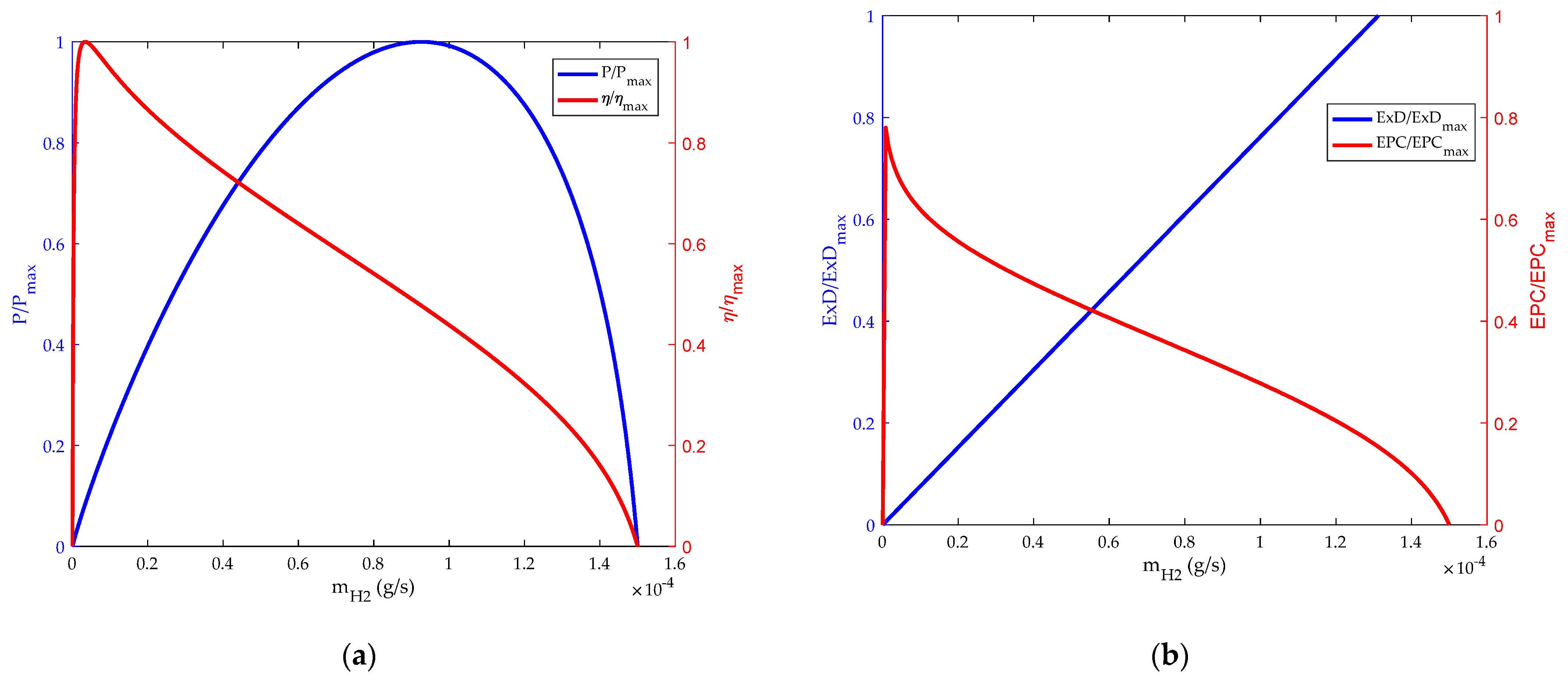
3.2. Influence of Inlet Flow Rate on HT-PEMFC

The changes of energy and exergetic performance based on hydrogen flow and air flow are shown in Figure 4 and Figure 5. It can be seen from Figure 4a and Figure 5a that the thermodynamic efficiency of HT-PEMFC has a maximum value in the region of low hydrogen and air flow. This is because in the initial stage the electrochemical reaction rate accelerates, and the power loss caused by polarization is small. With the increase of hydrogen and air flow, the thermodynamic efficiency of the HT-PEMFC will decrease. However, the power density will reach its maximum value at a specific hydrogen and oxygen flow rate. The main reason is that the output power of the HT-PEMFC increases with the increase of hydrogen and air flow rate. When the hydrogen and air flow rate are too high, the polarization phenomenon of the fuel cell is obvious, so the output voltage and power density decrease. Figure 4b and Figure 5b show the influence of hydrogen and air flow on EPC and exergy destruction rate. It can be seen that the value of EPC will reach the maximum at the initial stage and then decrease gradually. As can be seen from the figure, the curve characteristics of EPC and thermodynamic efficiency have similar trends, but they carry different implications. Thermodynamic efficiency represents the amount of fuel consumed to produce a certain amount of power, while EPC represents the destruction rate of availabilities.

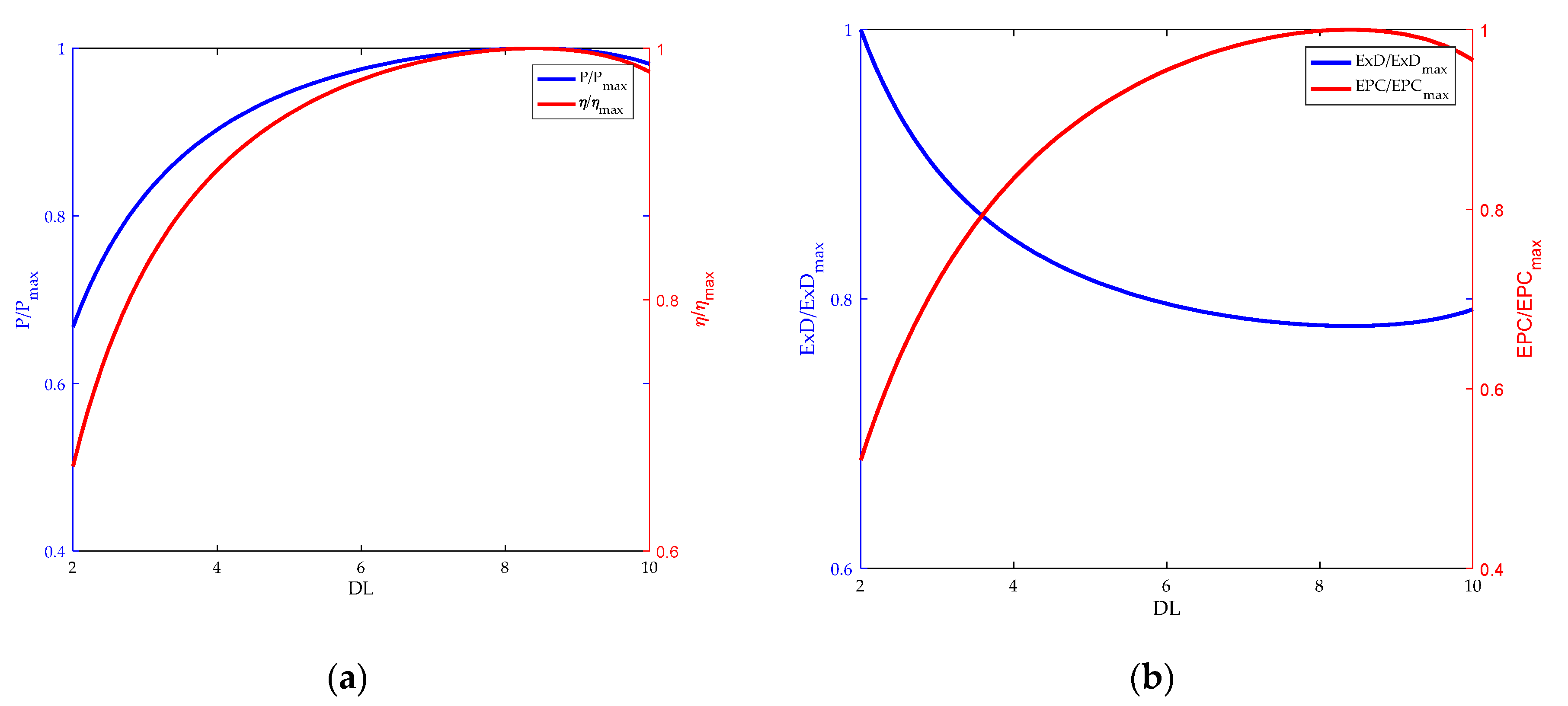
3.3. Influence of Doping Level on HT-PEMFC

The HT-PEMFC using the polybenzimidazole membrane doped with phosphoric acid molecules as electrolyte are studied in this paper. The doping level (DL) is the number of phosphoric acid molecules per polybenzimidazole (PBI). DL plays an important role in the ohmic overpotential. The relationship between the performance of HT-PEMFC and the doping level (DL) is shown in Figure 6. As the DL increases, the power density and energy efficiency reach the maximum value. When DL is further increased, the power density and energy efficiency decrease. When DL is 8, both power density and efficiency reach maximum values. As can be seen from Figure 6b, EPC acts as energy efficiency. However, when the exergy destruction rate reaches the minimum value, EPC is the maximum value. When energy efficiency and EPC are both maximized, the doping level is the same value. This is an expected result. Since minimum fuel consumption yields the maximum power at a certain power, environmental pollution is minimal, consistent with the maximum EPC. Hence, the optimal doping level is 8 in terms of E P C ,   P ,   E x D and η .

3.4. Influence of Inlet Pressure on HT-PEMFC

The inlet pressure is an important factor that affects the performance of HT-PEMFC. Figure 7 and Figure 8, respectively, represent the effects of hydrogen and oxygen inlet pressure on HT-PEMFC performance. As can be seen from the figure, both the power density and efficiency of HT-PEMFC increase as the hydrogen and oxygen inlet pressure increase from 1 to 5 atm with a step width of 1 atm [50], but the increase is not numerically significant. Increasing the inlet pressure, on the one hand, increases the diffusion rate of the gas, improves the mass transfer of the reaction gas. On the other hand, it increases the concentration of gas and reduces the influence of concentration polarization on reversible potential.

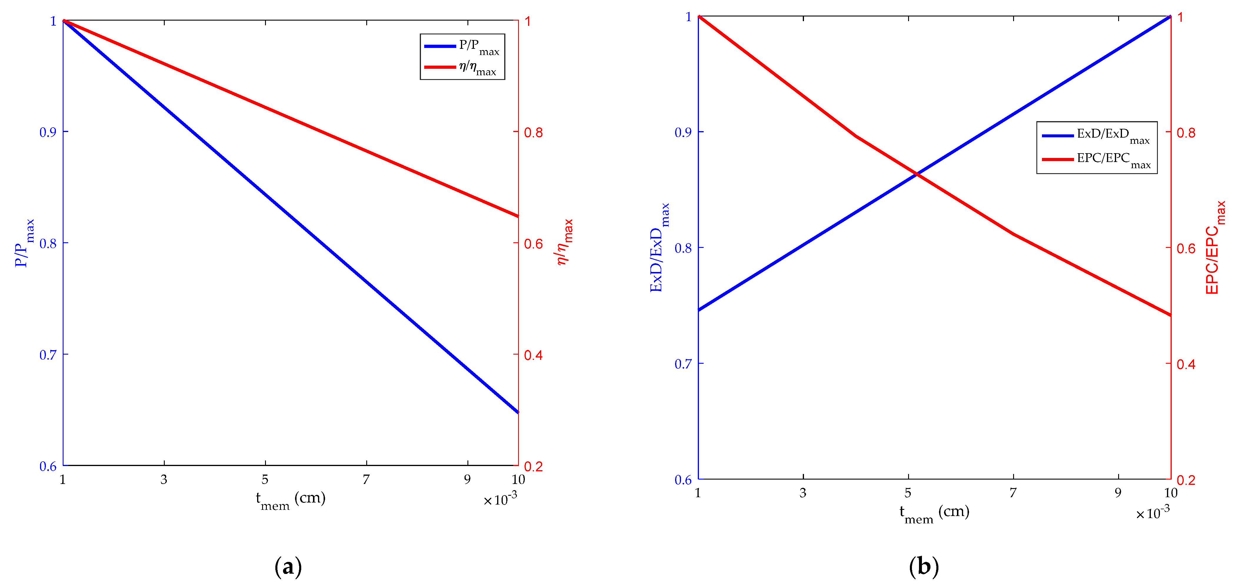
3.5. Influence of Film Thickness on HT-PEMFC

Figure 9 reflects the impact of t m e m on HT-PEMFC power, efficiency, exergy destruction rate and EPC. It is obvious that the power, efficiency and EPC all improve with the decrease of t m e m , mainly because of the thinning of the membrane and the path length of the ions between anode and cathode is reduced, resulting in the decrease of ohmic potential of HT-PEMFC. However, if the membrane is too thin, it will cause fuel penetration, short circuit, film rupture and other problems. Therefore, it is essential to select the high temperature membrane in a proper range.

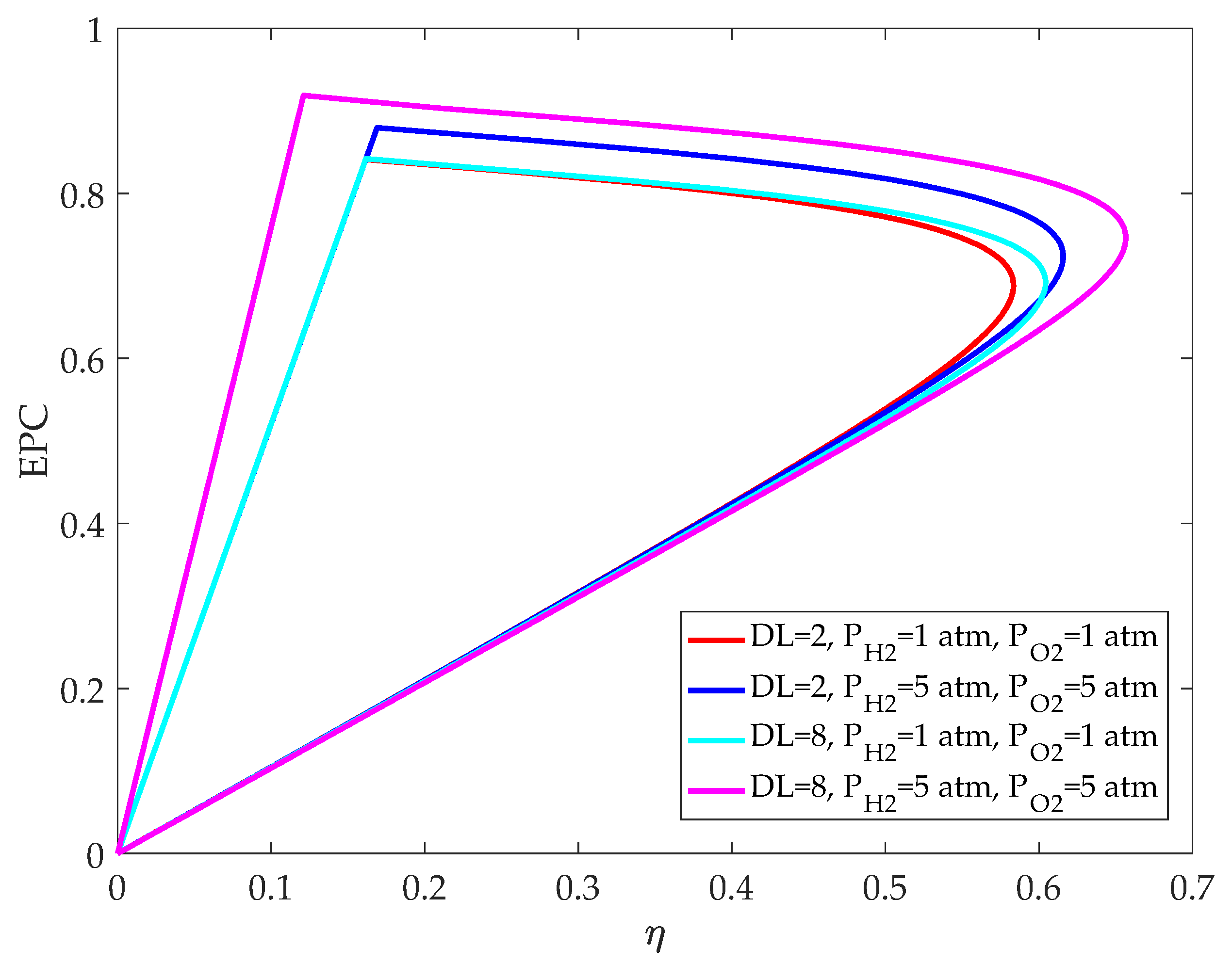
3.6. Relationship between EPC and Efficiency

Figure 10 shows the relationship between EPC and efficiency before and after optimization of HT-PEMFC parameters. It can be seen that when DL and the efficiency are the same, increasing the inlet pressure can significantly improve the EPC of HT-PEMFC, indicating that the operating pressure has an impact on the power density and exergy destruction rate. When the operating pressure is the same, it is obvious that the efficiency of HT-PEMFC is improved by optimizing DL. The efficiency and EPC of HT-PEMFC are significantly improved by increasing both the operating pressure and DL, which not only reduces fuel consumption, but also reduces energy loss. However, if DL is too high, the mechanical property will become worse and the phosphoric acid molecules will leak out of the HT-PEM more easily. Besides, a higher inlet pressure consumes additional power to compress the inlet reactants.
In practical application, when HT-PEMFC is applied to vehicles, the EPC and energy efficiency of HT-PEMFC can be improved by increasing inlet pressure and doping level. When EPC increases, it shows that HT-PEMFC can produce more energy by causing less dissipation in the environment. Moreover, as the energy efficiency increases, it indicates that the HT-PEMFC consumes less fuel for the same amount of energy. Therefore, the HT-PEMFC performs better in terms of power output and the ecological environment, taking into account better EPC and efficiency operating conditions.

4. Conclusions

The performance of an HT-PEMFC is analyzed based on a new standard named exergetic performance coefficient, which is defined as the ratio of power to exergy destruction rate. The relationship between exergetic performance coefficient (EPC), power density, exergy destruction rate and energy efficiency is obtained, and the result shows that EPC can replace power density as a new performance criterion. In the analysis of the HT-PEMFC model, the influence of different parameters on power density, energy efficiency, exergy destruction rate and EPC is analyzed. It is found that EPC and energy efficiency have the same trend, but different meanings. The E P C m a x represents the most energy obtained from the HT-PEMFC while causing the least dissipation in the environment. Therefore, the higher the EPC of the HT-PEMFC, the better the performance in terms of power and ecological environment. In addition, improving the inlet pressure can significantly boost EPC, and increasing DL can greatly enhance energy efficiency. For future research in the field of engineering, this new criterion can be used to analyze fuel cell vehicles.

Author Contributions

All of the authors contributed to publishing this article. The collection of materials and summarization of this article was done by Y.L., M.Z. and D.L. The simulation and analysis were done by Y.L. and D.L. The conceptual ideas, methodology and guidance for the research were provided by Z.M. and Z.L. All authors have read and agreed to the published version of the manuscript.

Funding

We gratefully acknowledge the financial support of the National Natural Science Foundation of China (No. 51176069) and Scientific Research Foundation of Nanjing Forestry University (No. GXL2018004).

Institutional Review Board Statement

Not applicable.

Informed Consent Statement

Not applicable.

Data Availability Statement

Not applicable.

Conflicts of Interest

The authors declare no conflict of interest.

References

  1. Reddy, E.H.; Monder, D.S.; Jayanti, S. Parametric study of an external coolant system for a high temperature polymer electrolyte membrane fuel cell. Appl. Therm. Eng. 2013, 58, 155–164. [Google Scholar] [CrossRef]
  2. Alpaydin, G.U.; Devrim, Y.; Colpan, C.O. Performance of an HT-PEMFC having a catalyst with graphene and multiwalled carbon nanotube support. Int. J. Energy Res. 2019, 43, 3578–3589. [Google Scholar] [CrossRef]
  3. Reddy, E.H.; Jayanti, S. Thermal management strategies for a 1 kWe stack of a high temperature proton exchange membrane fuel cell. Appl. Therm. Eng. 2012, 48, 465–475. [Google Scholar] [CrossRef]
  4. Devrim, Y.; Arica, E.D. Multi-walled carbon nanotubes decorated by platinum catalyst for high temperature PEM fuel cell. Int. J. Hydrogen Energy 2019, 44, 18951–18966. [Google Scholar] [CrossRef]
  5. Oono, Y.; Sounai, A.; Hori, M. Influence of the phosphoric acid-doping level in a polybenzimidazole membrane on the cell performance of high-temperature proton exchange membrane fuel cells. J. Power Sources 2009, 189, 943–949. [Google Scholar] [CrossRef]
  6. Lee, D.; Lim, J.W.; Lee, D.G. Cathode/anode integrated composite bipolar plate for high-temperature PEMFC. Compos. Struct. 2017, 167, 144–151. [Google Scholar] [CrossRef]
  7. Muthuraja, P.; Prakash, S.; Shanmugam, V.M.; Radhakrsihnan, S.; Manisankar, P. Novel perovskite structured calcium titanate-PBI composite membranes for high-temperature PEM fuel cells: Synthesis and characterizations. Int. J. Hydrogen Energy 2018, 43, 4763–4772. [Google Scholar] [CrossRef]
  8. Li, Q.F.; Rudbeck, H.C.; Chromik, A.; Jensen, J.O.; Pan, C.; Steenberg, T.; Calverley, M.; Bjerrum, N.J.; Kerres, J. Properties, degradation and high temperature fuel cell test of different types of PBI and PBI blend membranes. J. Membr. Sci. 2010, 347, 260–270. [Google Scholar] [CrossRef]
  9. Selvakumar, K.; Prabhu, M.R. Investigation on meta-polybenzimidazole blend with sulfonated PVdF-HFP proton conducting polymer electrolytes for HT-PEM fuel cell application. J. Mater. Sci.-Mater. Electron. 2018, 29, 15163–15173. [Google Scholar] [CrossRef]
  10. Lobato, J.; Rodrigo, M.A.; Linares, J.J.; Scott, K. Effect of the catalytic ink preparation method on the performance of high temperature polymer electrolyte membrane fuel cells. J. Power Sources 2006, 157, 284–292. [Google Scholar] [CrossRef]
  11. Durmayaz, A.; Sogut, O.S.; Sahin, B.; Yavuz, H. Optimization of thermal systems based on finite-time thermodynamics and thermoeconomics. Prog. Energy Combust. 2004, 30, 175–217. [Google Scholar] [CrossRef]
  12. Qin, X.Y.; Chen, L.G.; Ge, Y.L.; Sun, F.R. Finite Time Thermodynamic Studies on Absorption Thermodynamic Cycles: A State-of-the-Art Review. Arab. J. Sci. Eng. 2013, 38, 405–419. [Google Scholar] [CrossRef]
  13. Ge, Y.L.; Chen, L.G.; Sun, F.R. Progress in Finite Time Thermodynamic Studies for Internal Combustion Engine Cycles. Entropy 2016, 18, 139. [Google Scholar] [CrossRef] [Green Version]
  14. Li, C.J.; Liu, Y.; Xu, B.; Ma, Z.S. Finite Time Thermodynamic Optimization of an Irreversible Proton Exchange Membrane Fuel Cell for Vehicle Use. Processes 2019, 7, 419. [Google Scholar] [CrossRef] [Green Version]
  15. He, S.; Lin, L.Y.; Wu, Z.X.; Chen, Z.M. Application of Finite Element Analysis in Properties Test of Finger-jointed Lumber. J. Bioresour. Bioprod. 2020, 5, 124. [Google Scholar] [CrossRef]
  16. Yang, J.; Zhang, Y.C.; Zhou, L.; Zhang, F.S.; Jing, Y.; Huang, M.Z.; Liu, H.B. Quality-related monitoring of papermaking wastewater treatment processes using dynamic multiblock partial least squares. J. Bioresour. Bioprod. 2021; in press. [Google Scholar] [CrossRef]
  17. Zhao, X.Y.; Huang, Y.J.; Fu, H.Y.; Wang, Y.L.; Wang, Z. Deflection test and modal analysis of lightweight timber floors. J. Bioresour. Bioprod. 2021, 6, 266–278. [Google Scholar] [CrossRef]
  18. Hu, T.P.; Yu, Z.; Guo, L.; Xu, C.Y. Thermodynamic self-consistent dynamic model of wood dust explosion. J. For. Eng. 2019, 4, 29–34. [Google Scholar]
  19. Ji, X.L.; Yang, P. The exploration of the slope displacement with vegetation protection under different rainfall intensity. J. For. Eng. 2020, 5, 152–156. [Google Scholar]
  20. Li, X.S.; Deng, T.T.; Wang, M.H.; Ju, S.; Li, X.C.; Li, M. Linear positioning algorithm improvement of wood acoustic emission source based on wavelet and signal correlation analysis methods. J. For. Eng. 2020, 5, 138–143. [Google Scholar]
  21. Xu, B.; Li, D.X.; Ma, Z.S.; Zheng, M.; Li, Y.J. Thermodynamic Optimization of a High Temperature Proton Exchange Membrane Fuel Cell for Fuel Cell Vehicle Applications. Mathematics 2021, 9, 1792. [Google Scholar] [CrossRef]
  22. Guo, Y.H.; Guo, X.R.; Zhang, H.C.; Hou, S.J. Energetic, exergetic and ecological analyses of a high-temperature proton exchange membrane fuel cell based on a phosphoric-acid-doped polybenzimidazole membrane. Sustain. Energy Technol. Assesments 2020, 38, 100671. [Google Scholar] [CrossRef]
  23. Ye, L.; Jiao, K.; Du, Q.; Yin, Y. Exergy Analysis of High-Temperature Proton Exchange Membrane Fuel Cell Systems. Int. J. Green Energy 2015, 12, 917–929. [Google Scholar] [CrossRef]
  24. Guo, X.R.; Zhang, H.C.; Yuan, J.L.; Wang, J.T.; Zhao, J.P.; Wang, F.; Miao, H.; Hou, S.J. Energetic and exergetic analyses of a combined system consisting of a high-temperature polymer electrolyte membrane fuel cell and a thermoelectric generator with Thomson effect. Int. J. Hydrogen Energy 2019, 44, 16918–16932. [Google Scholar] [CrossRef]
  25. Liu, G.K.; Qin, Y.Z.; Yin, Y.F.; Bian, X.Z.; Kuang, C.C. Thermodynamic modeling and exergy analysis of proton exchange membrane fuel cell power system. Int. J. Hydrogen Energy 2020, 45, 29799–29811. [Google Scholar] [CrossRef]
  26. Li, D.; Li, S.; Ma, Z.; Xu, B.; Lu, Z.; Li, Y.; Zheng, M. Ecological Performance Optimization of a High Temperature Proton Exchange Membrane Fuel Cell. Mathematics 2021, 9, 1332. [Google Scholar] [CrossRef]
  27. Huang, Y.W.; Ding, H.; Zou, Y.F. Ecological Performance Analysis of an Integrated Proton Exchange Membrane Fuel Cell and Thermoelectric Devices. Int. J. Electrochem. Sci. 2020, 15, 2581–2593. [Google Scholar] [CrossRef]
  28. Li, C.J.; Xu, B.; Ma, Z.S. Ecological Performance of an Irreversible Proton Exchange Membrane Fuel Cell. Sci. Adv. Mater. 2020, 12, 1225–1235. [Google Scholar] [CrossRef]
  29. Peng, X.R.; Zhang, Z.K.; Zhao, L.Y. Analysis of Raman spectroscopy and XPS of plasma modified polypropylene decorative film. J. For. Eng. 2020, 5, 45–51. [Google Scholar]
  30. Yu, P.J.; Zhang, W.; Chen, M.Z.; Zhou, X.Y. Plasma-treated thermoplastic resin film as adhesive for preparing environmentally-friendly plywood. J. For. Eng. 2020, 5, 41–47. [Google Scholar]
  31. Liu, S.Q.; Jia, L.M. Review on sustainable development of forest-based biodiesel. J. Nanjing For. Univ. (Nat. Sci. Ed.) 2021, 44, 216–224. [Google Scholar]
  32. Xiong, G.K.; Li, Y.Q.; Xiong, Y.Q.; Duan, A.G.; Cao, D.C.; Sun, J.J.; Nie, L.Y.; Sheng, W.T. Effects of low stand density afforestation on the growth, stem-form and timber assortment structure of Cunninghamia lanceolata plantations. J. Nanjing For. Univ. (Nat. Sci. Ed.) 2021, 45, 165–173. [Google Scholar] [CrossRef]
  33. Yao, J.J.; Feng, X.Q.; Xiao, H.; Zheng, Y.; Zhang, C.L. Improvement effects of different solid waste and their disposal by products on saline-alkali soil in Huanghua Port. J. Nanjing For. Univ. (Nat. Sci. Ed.) 2021, 45, 45–52. [Google Scholar] [CrossRef]
  34. Zhang, Z.G. Researches on green features and category architecture of green strategies of renewable-resource-based enterprises: A case study of forestry enterprise. J. Nanjing For. Univ. (Nat. Sci. Ed.) 2020, 44, 1–8. [Google Scholar] [CrossRef]
  35. Zhou, S.J.; Wang, P.; Zhang, M.; Chen, S.Z.; Xu, W.; Zhu, L.T.; He, X.Q.; Gong, S.R. Effects of atmospheric acid deposition on root physiological characteristics of Pinus massoniana seedlings. J. Nanjing For. Univ. (Nat. Sci. Ed.) 2021, 44, 111–118. [Google Scholar] [CrossRef]
  36. Zhu, P.H.; Chen, Y.; Ji, K.S. A review of terpene synthases and genes in Pinaceae. J. Nanjing For. Univ. (Nat. Sci. Ed.) 2021, 45, 233–244. [Google Scholar] [CrossRef]
  37. Watowich, S.J.; Berry, R.S. Optimal current paths for model electrochemical systems. J. Phys. Chem. 1986, 90, 4624–4631. [Google Scholar] [CrossRef]
  38. Sieniutycz, S. Thermodynamics of Power Production in Fuel Cells. Chem. Process. Eng.-Inz. 2010, 31, 81–105. [Google Scholar]
  39. Sieniutycz, S.; Poswiata, A. Thermodynamic aspects of power production in thermal, chemical and electrochemical systems. Energy 2012, 45, 62–70. [Google Scholar] [CrossRef]
  40. Akkaya, A.V.; Sahin, B.; Erdem, H.H. Exergetic performance coefficient analysis of a simple fuel cell system. Int. J. Hydrogen Energy 2007, 32, 4600–4609. [Google Scholar] [CrossRef]
  41. Guo, X.R.; Zhang, H.C.; Zhao, J.P.; Wang, F.; Wang, J.T.; Miao, H.; Yuan, J.L. Performance evaluation of an integrated high-temperature proton exchange membrane fuel cell and absorption cycle system for power and heating/cooling cogeneration. Energy Convers. Manag. 2019, 181, 292–301. [Google Scholar] [CrossRef]
  42. Dincer, I.; Hussain, M.M.; Al-Zaharnah, I. Energy and exergy utilization in agricultural sector of Saudi Arabia. Energy Policy 2005, 33, 1461–1467. [Google Scholar] [CrossRef]
  43. Al-Sulaiman, F.A.; Dincer, I.; Hamdullahpur, F. Energy and exergy analyses of a biomass trigeneration system using an organic Rankine cycle. Energy 2012, 45, 975–985. [Google Scholar] [CrossRef]
  44. Xu, X.M.; Zhang, L.; Jiang, Y.P.; Chen, N. Active Control on Path Following and Lateral Stability for Truck-Trailer Combi-nations. Arab. J. Sci. Eng. 2019, 44, 1365–1377. [Google Scholar] [CrossRef]
  45. Zhou, W.L.; Zheng, Y.P.; Pan, Z.J.; Lu, Q. Review on the Battery Model and SOC Estimation Method. Processes 2021, 9, 1685. [Google Scholar] [CrossRef]
  46. Chang, C.C.; Zheng, Y.P.; Sun, W.M.; Ma, Z.S. LPV Estimation of SOC Based on Electricity Conversion and Hysteresis Characteristic. J. Energy Eng. 2019, 145, 04019026. [Google Scholar] [CrossRef]
  47. Tian, J.; Zeng, Q.K.; Wang, P.; Wang, X.Q. Active steering control based on preview theory for articulated heavy vehicles. PLoS ONE 2021, 16, e0252098. [Google Scholar] [CrossRef]
  48. Xu, X.M.; Lin, P. Parameter identification of sound absorption model of porous materials based on modified particle swarm optimization algorithm. PLoS ONE 2021, 16, e0250950. [Google Scholar] [CrossRef]
  49. Xu, X.M.; Chen, D.; Zhang, L.; Chen, N. Hopf Bifurcation Characteristics of the Vehicle with Rear Axle Compliance Steering. Shock. Vib. 2019, 2019, 3402084. [Google Scholar] [CrossRef] [Green Version]
  50. Ribeirinha, P.; Abdollahzadeh, M.; Pereira, A.; Relvas, F.; Boaventura, M.; Mendes, A. High temperature PEM fuel cell integrated with a cellular membrane methanol steam reformer: Experimental and modelling. Appl. Energy 2018, 215, 659–669. [Google Scholar] [CrossRef]
Figure 1. Working principle of high-temperature proton exchange membrane fuel cell (HT-PEMFC).
Membranes 12 00070 g001
Figure 2. Exergetic equilibrium of the HT-PEMFC.
Membranes 12 00070 g002
Figure 3. Relationship between efficiency and dimensionless E P C ,   P ,   E x D .
Membranes 12 00070 g003
Figure 4. Influence of hydrogen flow rate. (a) Power density and energy efficiency; (b) exergy destruction rate and exergetic performance coefficient.
Membranes 12 00070 g004
Figure 5. Influence of air flow rate. (a) power density and energy efficiency; (b) exergy destruction rate and exergetic performance coefficient.
Membranes 12 00070 g005
Figure 6. Influence of doping level. (a) Power density and energy efficiency; (b) exergy destruction rate and exergetic performance coefficient.
Membranes 12 00070 g006
Figure 7. Influence of hydrogen pressure. (a) Power density and energy efficiency; (b) exergy destruction rate and exergetic performance coefficient.
Membranes 12 00070 g007
Figure 8. Influence of oxygen pressure. (a) Power density and energy efficiency; (b) exergy destruction rate and exergetic performance coefficient.
Membranes 12 00070 g008
Figure 9. Influence of film thickness. (a) Power density and energy efficiency; (b) exergy destruction rate and exergetic performance coefficient.
Membranes 12 00070 g009
Figure 10. Exergetic performance coefficient versus energy efficiency before and after optimizing.
Membranes 12 00070 g010
Table 1. Parameters used in the modeling.
ParameterValue
Faraday constant, F   ( C   mol 1 ) 96,485
Gas constant, R   ( J   mol 1   K 1 ) 8.314
Number of electrons, n 2
Operating temperature, T   ( K ) 438 [22]
Anode pressure ( atm )1 [22]
Cathode pressure ( atm )1 [22]
Anode gas compositions100% H 2 [22]
Cathode gas compositions21% O 2 / 79 %   N 2 [22]
The doping level, D L 10 [26]
The relative humidity, R H 3.8% [26]
Thickness of the electrolyte, t m e m   ( cm ) 0.005 [26]
Table 2. Variation ranges of p , D L and t m e m .
ParameterValue
Hydrogen pressure, p H 2   ( atm ) 1–5 [21]
Oxygen pressure, p O 2   ( atm ) 1–5 [21]
The doping level, D L 2–10 [22,26]
Thickness of the electrolyte, t m e m   ( cm ) 0.001–0.01 [21]
Publisher’s Note: MDPI stays neutral with regard to jurisdictional claims in published maps and institutional affiliations.

