O-Arm Navigated Frameless and Fiducial-Less Deep Brain Stimulation

 , ,
, ,
Abstract
:1. Introduction
2. Methods
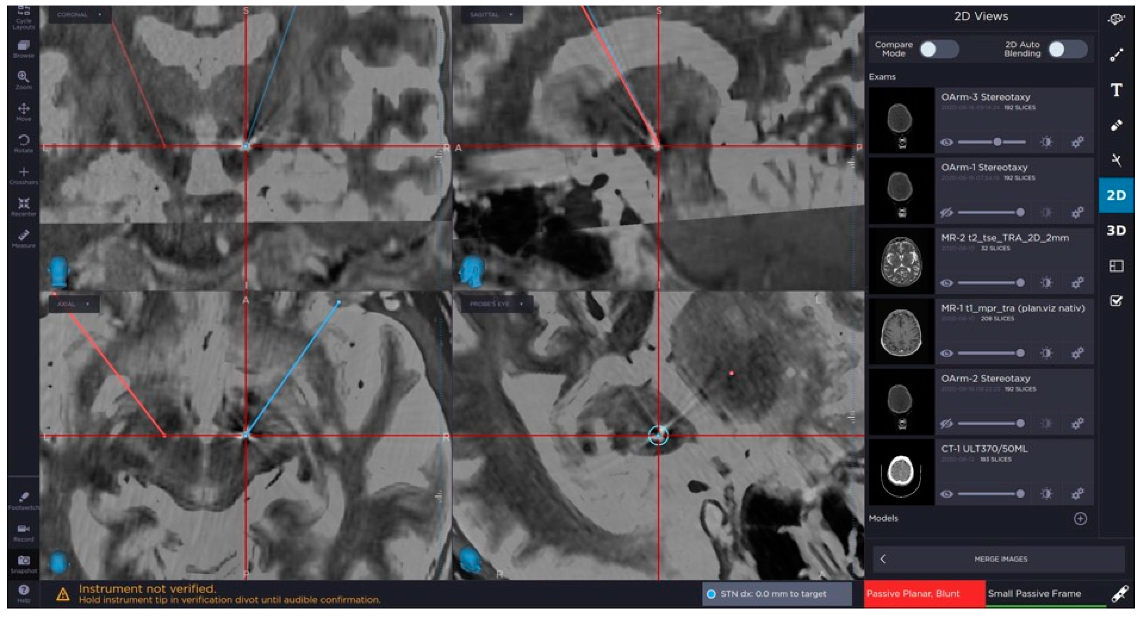
2.1. Imaging
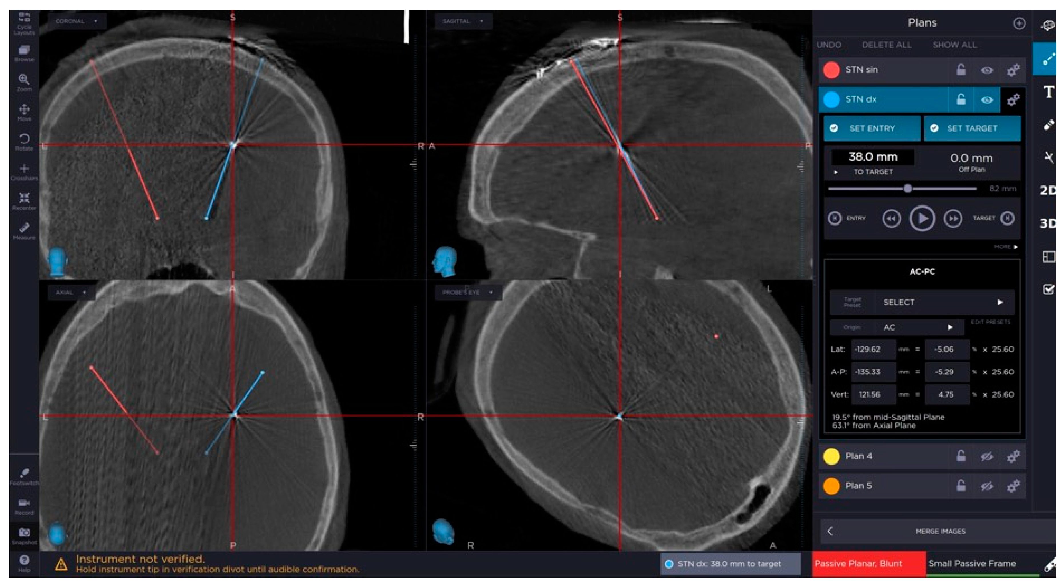
2.2. Surgical Technique
2.3. Intraoperative Microelectrode Registration (MER)
2.4. Macro-Test Stimulation
2.5. Lead Anchoring and Implantable Pulse Generator Placement
3. Results
4. Discussion
5. Conclusions
Author Contributions
Funding
Conflicts of Interest
References
- Deuschl, G.; Paschen, S.; Witt, K. Clinical outcome of deep brain stimulation for Parkinson’s disease. In Handbook of Clinical Neurology; Elsevier B.V.: Amsterdam, The Netherlands, 2013; Volume 116, pp. 107–128. [Google Scholar]
- Weaver, F.M.; Follett, K.; Stern, M.; Hur, K.; Harris, C.; Marks, W.J.; Rothlind, J.; Sagher, O.; Reda, D.; Moy, C.S.; et al. Bilateral deep brain stimulation vs best medical therapy for patients with advanced parkinson disease: A randomized controlled trial. JAMA J. Am. Med. Assoc. 2009, 301, 63–73. [Google Scholar] [CrossRef] [PubMed]
- Benabid, A.L.; Pollak, P.; Hoffmann, D.; Gervason, C.; Hommel, M.; Perret, J.E.; de Rougemont, J.; Gao, D.M. Long-term suppression of tremor by chronic stimulation of the ventral intermediate thalamic nucleus. Lancet 1991, 337, 403–406. [Google Scholar] [CrossRef]
- Kupsch, A.; Benecke, R.; Müller, J.; Trottenberg, T.; Schneider, G.H.; Poewe, W.; Eisner, W.; Wolters, A.; Müller, J.U.; Deuschl, G.; et al. Pallidal deep-brain stimulation in primary generalized or segmental dystonia. N. Engl. J. Med. 2006, 355, 1978–1990. [Google Scholar] [CrossRef] [PubMed]
- Vidailhet, M.; Vercueil, L.; Houeto, J.L.; Krystkowiak, P.; Benabid, A.L.; Cornu, P.; Lagrange, C.; Du Montcel, S.T.; Dormont, D.; Grand, S.; et al. Bilateral deep-brain stimulation of the globus pallidus in primary generalized dystonia. N. Engl. J. Med. 2005, 352, 459–467. [Google Scholar] [CrossRef] [PubMed]
- Benabid, A.L.; Chabardes, S.; Mitrofanis, J.; Pollak, P. Deep brain stimulation of the subthalamic nucleus for the treatment of Parkinson’s disease. Lancet Neurol. 2009, 8, 67–81. [Google Scholar] [CrossRef]
- Schuepbach, W.M.M.; Rau, J.; Knudsen, K.; Volkmann, J.; Krack, P.; Timmermann, L.; Hälbig, T.D.; Hesekamp, H.; Navarro, S.M.; Meier, N.; et al. Neurostimulation for Parkinson’s disease with early motor complications. N. Engl. J. Med. 2013, 368, 610–622. [Google Scholar] [CrossRef] [PubMed]
- Moro, E.; Schüpbach, M.; Wächter, T.; Allert, N.; Eleopra, R.; Honey, C.R.; Rueda, M.; Schiess, M.C.; Shimo, Y.; Valkovic, P.; et al. Referring Parkinson’s disease patients for deep brain stimulation: A RAND/UCLA appropriateness study. J. Neurol. 2016, 263, 112–119. [Google Scholar] [CrossRef] [PubMed]
- Toms, J.; Martin, S.; Sima, A.P.; Chung, A.; Docef, A.; Holloway, K.L. A Comparative Study of Fiducial-Based and Fiducial-Less Registration Utilizing the O-Arm. Stereotact. Funct. Neurosurg. 2019, 97, 83–93. [Google Scholar] [CrossRef] [PubMed]
- Holewijn, R.A.; Bot, M.; van den Munckhof, P.; Schuurman, P.R. Implementation of Intraoperative Cone-Beam Computed Tomography (O-arm) for Stereotactic Imaging During Deep Brain Stimulation Procedures. Oper. Neurosurg. (Hagerstown Md.) 2020, 19, E224–E229. [Google Scholar] [CrossRef] [PubMed]
- Postuma, R.B.; Berg, D.; Stern, M.; Poewe, W.; Olanow, C.W.; Oertel, W.; Obeso, J.; Marek, K.; Litvan, I.; Lang, A.E.; et al. MDS clinical diagnostic criteria for Parkinson’s disease. Mov. Disord. 2015, 30, 1591–1601. [Google Scholar] [CrossRef] [PubMed]
- Krahulík, D.; Nevrlý, M.; Otruba, P.; Bardon, J.; Hrabálek, L.; Vaverka, M.; Kaňovský, P. Placement accuracy of deep brain stimulation electrodes using the NexFrame© frameless system. Ces. Slov. Neurol. Neurochir. 2017, 80, 208–212. [Google Scholar] [CrossRef]
- Hemler, P.F.; Sumanaweera, T.S.; van den Elsen, P.A.; Napel, S.; Adler, J. A versatile system for multimodality image fusion. Comput. Aided Surg. 1995, 1, 35–45. [Google Scholar] [CrossRef]
- Urgošík, D.; Jech, R.; Růžička, E. Deep brain stimulation in patients suffering from movement disorders—Stereotactic procedure and intraoperative findings | Hluboká mozková stimulace u nemocných s extrapyramidovými poruchami pohybu -Stereotaktická procedura a intraoperační nálezy. Ces. Slov. Neurol. Neurochir. 2011, 74, 175–186. [Google Scholar]
- Rohlfing, T.; Maurer, C.R.; Dean, D.; Maciunas, R.J.; Lozano, A.M.; Gildenberg, P.L.; Kelly, P.J.; Burchiel, K.J.; Christiano, J.C.; Rezai, A.R.; et al. Effect of changing patient position from supine to prone on the accuracy of a brown-roberts-wells stereotactic head frame system. Neurosurgery 2003, 52, 610–618. [Google Scholar] [CrossRef] [PubMed]
- Holloway, K.L.; Gaede, S.E.; Starr, P.A.; Rosenow, J.M.; Ramakrishnan, V.; Henderson, J.M. Frameless stereotaxy using bone fiducial markers for deep brain stimulation. J. Neurosurg. 2005, 103, 404–413. [Google Scholar] [CrossRef] [PubMed]


| Procedure | Total Error (mm) | Lateral Axis | AP axis | Vertical Axis |
|---|---|---|---|---|
| FL | 1.79 ± 0.68 | 1.10 ± 0.78 | 1.37 ± 0.87 | 1.21 ± 0.9 |
| FB | 1.64 ± 0.81 | 1.03 ± 0.79 | 1.14 ± 0.95 | 1.05 ± 0.91 |
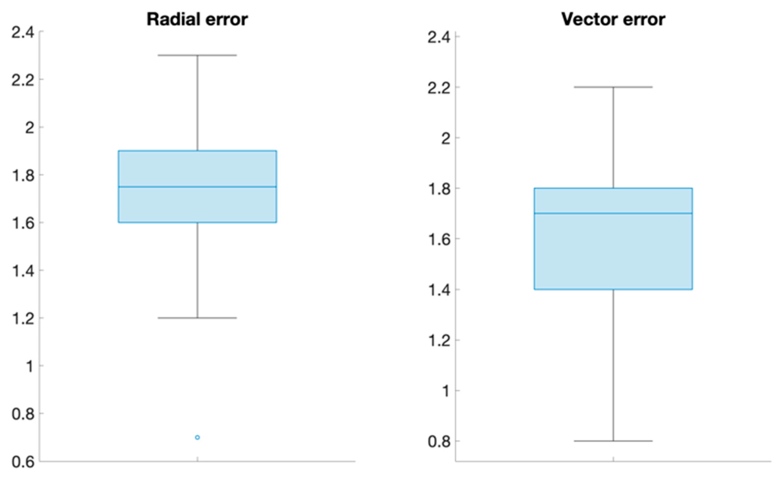
| Error Measure | Total Error (mm) |
|---|---|
| Radial error | 1.71 (0.32) |
| Vector error | 1.63 (0.34) |
| Radial A-P | 1.1 (0.56) |
| Radial M-L | 1.0 (0.34) |
© 2020 by the authors. Licensee MDPI, Basel, Switzerland. This article is an open access article distributed under the terms and conditions of the Creative Commons Attribution (CC BY) license (http://creativecommons.org/licenses/by/4.0/).
Share and Cite
Krahulík, D.; Nevrlý, M.; Otruba, P.; Bardoň, J.; Hrabálek, L.; Pohlodek, D.; Kaňovský, P.; Valošek, J. O-Arm Navigated Frameless and Fiducial-Less Deep Brain Stimulation. Brain Sci. 2020, 10, 683. https://doi.org/10.3390/brainsci10100683
Krahulík D, Nevrlý M, Otruba P, Bardoň J, Hrabálek L, Pohlodek D, Kaňovský P, Valošek J. O-Arm Navigated Frameless and Fiducial-Less Deep Brain Stimulation. Brain Sciences. 2020; 10(10):683. https://doi.org/10.3390/brainsci10100683
Chicago/Turabian StyleKrahulík, David, Martin Nevrlý, Pavel Otruba, Jan Bardoň, Lumír Hrabálek, Daniel Pohlodek, Petr Kaňovský, and Jan Valošek. 2020. "O-Arm Navigated Frameless and Fiducial-Less Deep Brain Stimulation" Brain Sciences 10, no. 10: 683. https://doi.org/10.3390/brainsci10100683
APA StyleKrahulík, D., Nevrlý, M., Otruba, P., Bardoň, J., Hrabálek, L., Pohlodek, D., Kaňovský, P., & Valošek, J. (2020). O-Arm Navigated Frameless and Fiducial-Less Deep Brain Stimulation. Brain Sciences, 10(10), 683. https://doi.org/10.3390/brainsci10100683